US6458092B1 - Vascular inducing implants - Google Patents
Vascular inducing implants Download PDFInfo
- Publication number
- US6458092B1 US6458092B1 US09/164,173 US16417398A US6458092B1 US 6458092 B1 US6458092 B1 US 6458092B1 US 16417398 A US16417398 A US 16417398A US 6458092 B1 US6458092 B1 US 6458092B1
- Authority
- US
- United States
- Prior art keywords
- implant
- tissue
- configuration
- profile
- implants
- Prior art date
- Legal status (The legal status is an assumption and is not a legal conclusion. Google has not performed a legal analysis and makes no representation as to the accuracy of the status listed.)
- Expired - Fee Related
Links
- 239000007943 implant Substances 0.000 title claims abstract description 298
- 230000001939 inductive effect Effects 0.000 title description 7
- 230000002792 vascular Effects 0.000 title description 7
- 230000033115 angiogenesis Effects 0.000 claims abstract description 42
- 239000000126 substance Substances 0.000 claims abstract description 34
- 230000002491 angiogenic effect Effects 0.000 claims abstract description 22
- 208000007536 Thrombosis Diseases 0.000 claims abstract description 19
- 238000002513 implantation Methods 0.000 claims abstract description 18
- 230000008458 response to injury Effects 0.000 claims abstract description 10
- 230000001737 promoting effect Effects 0.000 claims abstract description 8
- 230000015572 biosynthetic process Effects 0.000 claims description 4
- 239000011248 coating agent Substances 0.000 claims description 2
- 238000000576 coating method Methods 0.000 claims description 2
- 210000004369 blood Anatomy 0.000 abstract description 40
- 239000008280 blood Substances 0.000 abstract description 40
- 230000000302 ischemic effect Effects 0.000 abstract description 25
- 210000004165 myocardium Anatomy 0.000 abstract description 25
- 230000035876 healing Effects 0.000 abstract description 8
- 102000009123 Fibrin Human genes 0.000 abstract description 7
- 108010073385 Fibrin Proteins 0.000 abstract description 7
- BWGVNKXGVNDBDI-UHFFFAOYSA-N Fibrin monomer Chemical compound CNC(=O)CNC(=O)CN BWGVNKXGVNDBDI-UHFFFAOYSA-N 0.000 abstract description 7
- 229950003499 fibrin Drugs 0.000 abstract description 7
- 230000000977 initiatory effect Effects 0.000 abstract description 5
- 238000011176 pooling Methods 0.000 abstract description 2
- 210000001519 tissue Anatomy 0.000 description 218
- 238000000034 method Methods 0.000 description 28
- 208000027418 Wounds and injury Diseases 0.000 description 18
- 239000000463 material Substances 0.000 description 16
- 208000014674 injury Diseases 0.000 description 15
- 230000033001 locomotion Effects 0.000 description 15
- 230000002107 myocardial effect Effects 0.000 description 14
- 230000006378 damage Effects 0.000 description 13
- 210000005240 left ventricle Anatomy 0.000 description 12
- 230000017531 blood circulation Effects 0.000 description 8
- 230000007794 irritation Effects 0.000 description 8
- 230000001965 increasing effect Effects 0.000 description 7
- 208000028867 ischemia Diseases 0.000 description 7
- 210000004204 blood vessel Anatomy 0.000 description 6
- 210000003205 muscle Anatomy 0.000 description 6
- 230000008569 process Effects 0.000 description 6
- 230000006870 function Effects 0.000 description 5
- 238000003780 insertion Methods 0.000 description 5
- 230000037431 insertion Effects 0.000 description 5
- 230000007246 mechanism Effects 0.000 description 5
- 230000000149 penetrating effect Effects 0.000 description 5
- 239000007787 solid Substances 0.000 description 5
- 239000010935 stainless steel Substances 0.000 description 5
- 229910001220 stainless steel Inorganic materials 0.000 description 5
- 210000004351 coronary vessel Anatomy 0.000 description 4
- 230000004044 response Effects 0.000 description 4
- 238000013459 approach Methods 0.000 description 3
- 239000003102 growth factor Substances 0.000 description 3
- 239000002184 metal Substances 0.000 description 3
- 230000003387 muscular Effects 0.000 description 3
- 239000004033 plastic Substances 0.000 description 3
- 229920000642 polymer Polymers 0.000 description 3
- 238000005299 abrasion Methods 0.000 description 2
- 210000002565 arteriole Anatomy 0.000 description 2
- 230000036770 blood supply Effects 0.000 description 2
- 208000029078 coronary artery disease Diseases 0.000 description 2
- 239000003814 drug Substances 0.000 description 2
- 229940079593 drug Drugs 0.000 description 2
- 239000012530 fluid Substances 0.000 description 2
- 230000005012 migration Effects 0.000 description 2
- 238000013508 migration Methods 0.000 description 2
- 230000006911 nucleation Effects 0.000 description 2
- 238000010899 nucleation Methods 0.000 description 2
- 230000037361 pathway Effects 0.000 description 2
- 230000035515 penetration Effects 0.000 description 2
- 238000004904 shortening Methods 0.000 description 2
- 238000005476 soldering Methods 0.000 description 2
- 230000008733 trauma Effects 0.000 description 2
- 230000000472 traumatic effect Effects 0.000 description 2
- 238000003466 welding Methods 0.000 description 2
- 229920004934 Dacron® Polymers 0.000 description 1
- 206010029113 Neovascularisation Diseases 0.000 description 1
- 238000002679 ablation Methods 0.000 description 1
- 239000002251 absorbable suture material Substances 0.000 description 1
- 230000009471 action Effects 0.000 description 1
- 230000001154 acute effect Effects 0.000 description 1
- 239000000853 adhesive Substances 0.000 description 1
- 230000001070 adhesive effect Effects 0.000 description 1
- 229910045601 alloy Inorganic materials 0.000 description 1
- 239000000956 alloy Substances 0.000 description 1
- 238000004873 anchoring Methods 0.000 description 1
- 239000002870 angiogenesis inducing agent Substances 0.000 description 1
- 230000003466 anti-cipated effect Effects 0.000 description 1
- 210000000709 aorta Anatomy 0.000 description 1
- 210000001367 artery Anatomy 0.000 description 1
- QVGXLLKOCUKJST-UHFFFAOYSA-N atomic oxygen Chemical compound [O] QVGXLLKOCUKJST-UHFFFAOYSA-N 0.000 description 1
- 230000008901 benefit Effects 0.000 description 1
- 230000000747 cardiac effect Effects 0.000 description 1
- 230000008859 change Effects 0.000 description 1
- 230000004087 circulation Effects 0.000 description 1
- 238000010276 construction Methods 0.000 description 1
- 238000005516 engineering process Methods 0.000 description 1
- 239000004744 fabric Substances 0.000 description 1
- 238000010353 genetic engineering Methods 0.000 description 1
- 230000001771 impaired effect Effects 0.000 description 1
- 230000006698 induction Effects 0.000 description 1
- 238000002347 injection Methods 0.000 description 1
- 239000007924 injection Substances 0.000 description 1
- 238000007726 management method Methods 0.000 description 1
- 239000000203 mixture Substances 0.000 description 1
- 230000004048 modification Effects 0.000 description 1
- 238000012986 modification Methods 0.000 description 1
- 230000004118 muscle contraction Effects 0.000 description 1
- 208000031225 myocardial ischemia Diseases 0.000 description 1
- 229910052760 oxygen Inorganic materials 0.000 description 1
- 239000001301 oxygen Substances 0.000 description 1
- 239000005020 polyethylene terephthalate Substances 0.000 description 1
- 239000011148 porous material Substances 0.000 description 1
- 238000005381 potential energy Methods 0.000 description 1
- 238000005086 pumping Methods 0.000 description 1
- 230000012191 relaxation of muscle Effects 0.000 description 1
- 238000005096 rolling process Methods 0.000 description 1
- 210000004872 soft tissue Anatomy 0.000 description 1
- 229910000679 solder Inorganic materials 0.000 description 1
- 239000011343 solid material Substances 0.000 description 1
- 230000008093 supporting effect Effects 0.000 description 1
- 230000001225 therapeutic effect Effects 0.000 description 1
- 208000037816 tissue injury Diseases 0.000 description 1
Images


Classifications
-
- A—HUMAN NECESSITIES
- A61—MEDICAL OR VETERINARY SCIENCE; HYGIENE
- A61F—FILTERS IMPLANTABLE INTO BLOOD VESSELS; PROSTHESES; DEVICES PROVIDING PATENCY TO, OR PREVENTING COLLAPSING OF, TUBULAR STRUCTURES OF THE BODY, e.g. STENTS; ORTHOPAEDIC, NURSING OR CONTRACEPTIVE DEVICES; FOMENTATION; TREATMENT OR PROTECTION OF EYES OR EARS; BANDAGES, DRESSINGS OR ABSORBENT PADS; FIRST-AID KITS
- A61F2/00—Filters implantable into blood vessels; Prostheses, i.e. artificial substitutes or replacements for parts of the body; Appliances for connecting them with the body; Devices providing patency to, or preventing collapsing of, tubular structures of the body, e.g. stents
- A61F2/82—Devices providing patency to, or preventing collapsing of, tubular structures of the body, e.g. stents
- A61F2/94—Stents retaining their form, i.e. not being deformable, after placement in the predetermined place
-
- A—HUMAN NECESSITIES
- A61—MEDICAL OR VETERINARY SCIENCE; HYGIENE
- A61B—DIAGNOSIS; SURGERY; IDENTIFICATION
- A61B17/00—Surgical instruments, devices or methods, e.g. tourniquets
- A61B17/00234—Surgical instruments, devices or methods, e.g. tourniquets for minimally invasive surgery
-
- A—HUMAN NECESSITIES
- A61—MEDICAL OR VETERINARY SCIENCE; HYGIENE
- A61F—FILTERS IMPLANTABLE INTO BLOOD VESSELS; PROSTHESES; DEVICES PROVIDING PATENCY TO, OR PREVENTING COLLAPSING OF, TUBULAR STRUCTURES OF THE BODY, e.g. STENTS; ORTHOPAEDIC, NURSING OR CONTRACEPTIVE DEVICES; FOMENTATION; TREATMENT OR PROTECTION OF EYES OR EARS; BANDAGES, DRESSINGS OR ABSORBENT PADS; FIRST-AID KITS
- A61F2/00—Filters implantable into blood vessels; Prostheses, i.e. artificial substitutes or replacements for parts of the body; Appliances for connecting them with the body; Devices providing patency to, or preventing collapsing of, tubular structures of the body, e.g. stents
- A61F2/02—Prostheses implantable into the body
- A61F2/04—Hollow or tubular parts of organs, e.g. bladders, tracheae, bronchi or bile ducts
- A61F2/06—Blood vessels
-
- A—HUMAN NECESSITIES
- A61—MEDICAL OR VETERINARY SCIENCE; HYGIENE
- A61F—FILTERS IMPLANTABLE INTO BLOOD VESSELS; PROSTHESES; DEVICES PROVIDING PATENCY TO, OR PREVENTING COLLAPSING OF, TUBULAR STRUCTURES OF THE BODY, e.g. STENTS; ORTHOPAEDIC, NURSING OR CONTRACEPTIVE DEVICES; FOMENTATION; TREATMENT OR PROTECTION OF EYES OR EARS; BANDAGES, DRESSINGS OR ABSORBENT PADS; FIRST-AID KITS
- A61F2/00—Filters implantable into blood vessels; Prostheses, i.e. artificial substitutes or replacements for parts of the body; Appliances for connecting them with the body; Devices providing patency to, or preventing collapsing of, tubular structures of the body, e.g. stents
- A61F2/02—Prostheses implantable into the body
- A61F2/24—Heart valves ; Vascular valves, e.g. venous valves; Heart implants, e.g. passive devices for improving the function of the native valve or the heart muscle; Transmyocardial revascularisation [TMR] devices; Valves implantable in the body
- A61F2/2493—Transmyocardial revascularisation [TMR] devices
-
- A—HUMAN NECESSITIES
- A61—MEDICAL OR VETERINARY SCIENCE; HYGIENE
- A61B—DIAGNOSIS; SURGERY; IDENTIFICATION
- A61B17/00—Surgical instruments, devices or methods, e.g. tourniquets
- A61B17/00234—Surgical instruments, devices or methods, e.g. tourniquets for minimally invasive surgery
- A61B2017/00238—Type of minimally invasive operation
- A61B2017/00243—Type of minimally invasive operation cardiac
-
- A—HUMAN NECESSITIES
- A61—MEDICAL OR VETERINARY SCIENCE; HYGIENE
- A61F—FILTERS IMPLANTABLE INTO BLOOD VESSELS; PROSTHESES; DEVICES PROVIDING PATENCY TO, OR PREVENTING COLLAPSING OF, TUBULAR STRUCTURES OF THE BODY, e.g. STENTS; ORTHOPAEDIC, NURSING OR CONTRACEPTIVE DEVICES; FOMENTATION; TREATMENT OR PROTECTION OF EYES OR EARS; BANDAGES, DRESSINGS OR ABSORBENT PADS; FIRST-AID KITS
- A61F2220/00—Fixations or connections for prostheses classified in groups A61F2/00 - A61F2/26 or A61F2/82 or A61F9/00 or A61F11/00 or subgroups thereof
- A61F2220/0008—Fixation appliances for connecting prostheses to the body
- A61F2220/0016—Fixation appliances for connecting prostheses to the body with sharp anchoring protrusions, e.g. barbs, pins, spikes
-
- A—HUMAN NECESSITIES
- A61—MEDICAL OR VETERINARY SCIENCE; HYGIENE
- A61F—FILTERS IMPLANTABLE INTO BLOOD VESSELS; PROSTHESES; DEVICES PROVIDING PATENCY TO, OR PREVENTING COLLAPSING OF, TUBULAR STRUCTURES OF THE BODY, e.g. STENTS; ORTHOPAEDIC, NURSING OR CONTRACEPTIVE DEVICES; FOMENTATION; TREATMENT OR PROTECTION OF EYES OR EARS; BANDAGES, DRESSINGS OR ABSORBENT PADS; FIRST-AID KITS
- A61F2220/00—Fixations or connections for prostheses classified in groups A61F2/00 - A61F2/26 or A61F2/82 or A61F9/00 or A61F11/00 or subgroups thereof
- A61F2220/0025—Connections or couplings between prosthetic parts, e.g. between modular parts; Connecting elements
- A61F2220/005—Connections or couplings between prosthetic parts, e.g. between modular parts; Connecting elements using adhesives
-
- A—HUMAN NECESSITIES
- A61—MEDICAL OR VETERINARY SCIENCE; HYGIENE
- A61F—FILTERS IMPLANTABLE INTO BLOOD VESSELS; PROSTHESES; DEVICES PROVIDING PATENCY TO, OR PREVENTING COLLAPSING OF, TUBULAR STRUCTURES OF THE BODY, e.g. STENTS; ORTHOPAEDIC, NURSING OR CONTRACEPTIVE DEVICES; FOMENTATION; TREATMENT OR PROTECTION OF EYES OR EARS; BANDAGES, DRESSINGS OR ABSORBENT PADS; FIRST-AID KITS
- A61F2220/00—Fixations or connections for prostheses classified in groups A61F2/00 - A61F2/26 or A61F2/82 or A61F9/00 or A61F11/00 or subgroups thereof
- A61F2220/0025—Connections or couplings between prosthetic parts, e.g. between modular parts; Connecting elements
- A61F2220/0058—Connections or couplings between prosthetic parts, e.g. between modular parts; Connecting elements soldered or brazed or welded
-
- A—HUMAN NECESSITIES
- A61—MEDICAL OR VETERINARY SCIENCE; HYGIENE
- A61F—FILTERS IMPLANTABLE INTO BLOOD VESSELS; PROSTHESES; DEVICES PROVIDING PATENCY TO, OR PREVENTING COLLAPSING OF, TUBULAR STRUCTURES OF THE BODY, e.g. STENTS; ORTHOPAEDIC, NURSING OR CONTRACEPTIVE DEVICES; FOMENTATION; TREATMENT OR PROTECTION OF EYES OR EARS; BANDAGES, DRESSINGS OR ABSORBENT PADS; FIRST-AID KITS
- A61F2230/00—Geometry of prostheses classified in groups A61F2/00 - A61F2/26 or A61F2/82 or A61F9/00 or A61F11/00 or subgroups thereof
- A61F2230/0063—Three-dimensional shapes
- A61F2230/0073—Quadric-shaped
- A61F2230/0076—Quadric-shaped ellipsoidal or ovoid
-
- A—HUMAN NECESSITIES
- A61—MEDICAL OR VETERINARY SCIENCE; HYGIENE
- A61F—FILTERS IMPLANTABLE INTO BLOOD VESSELS; PROSTHESES; DEVICES PROVIDING PATENCY TO, OR PREVENTING COLLAPSING OF, TUBULAR STRUCTURES OF THE BODY, e.g. STENTS; ORTHOPAEDIC, NURSING OR CONTRACEPTIVE DEVICES; FOMENTATION; TREATMENT OR PROTECTION OF EYES OR EARS; BANDAGES, DRESSINGS OR ABSORBENT PADS; FIRST-AID KITS
- A61F2230/00—Geometry of prostheses classified in groups A61F2/00 - A61F2/26 or A61F2/82 or A61F9/00 or A61F11/00 or subgroups thereof
- A61F2230/0063—Three-dimensional shapes
- A61F2230/0091—Three-dimensional shapes helically-coiled or spirally-coiled, i.e. having a 2-D spiral cross-section
-
- A—HUMAN NECESSITIES
- A61—MEDICAL OR VETERINARY SCIENCE; HYGIENE
- A61F—FILTERS IMPLANTABLE INTO BLOOD VESSELS; PROSTHESES; DEVICES PROVIDING PATENCY TO, OR PREVENTING COLLAPSING OF, TUBULAR STRUCTURES OF THE BODY, e.g. STENTS; ORTHOPAEDIC, NURSING OR CONTRACEPTIVE DEVICES; FOMENTATION; TREATMENT OR PROTECTION OF EYES OR EARS; BANDAGES, DRESSINGS OR ABSORBENT PADS; FIRST-AID KITS
- A61F2250/00—Special features of prostheses classified in groups A61F2/00 - A61F2/26 or A61F2/82 or A61F9/00 or A61F11/00 or subgroups thereof
- A61F2250/0058—Additional features; Implant or prostheses properties not otherwise provided for
- A61F2250/0067—Means for introducing or releasing pharmaceutical products into the body
Definitions
- This invention relates to methods and devices for inducing angiogenesis in ischemic tissue.
- Tissue becomes ischemic when it is deprived of oxygenated blood. Blood may be present in such tissue, though it is not carrying oxygen. Ischemic tissue can be revived to function normally if it has remained viable despite the deprivation of oxygenated blood. Ischemia can be caused by a blockage in the vascular system that prohibits oxygenated blood from reaching the affected tissue area. Ischemia causes pain in the area of the affected tissue and in the case of muscle tissue can interrupt muscular function.
- ischemia can occur in various regions of the body, often tissue of the heart, the myocardium, is affected by ischemia due to coronary artery disease, occlusion of the coronary artery, which otherwise provides blood to the myocardium. Muscle tissue affected by ischemia can cause pain to the individual affected. Ischemia can be treated, if a tissue has remained viable despite the deprivation of oxygenated blood, by restoring blood flow to the affected tissue.
- Coronary artery bypass grafting CABG involves grating a venous segment between the aorta and the coronary artery to bypass the occluded portion of the artery. Once blood flow is redirected to the portion of the coronary artery beyond the occlusion, the supply of oxygenated blood is restored to the area of ischemic tissue.
- TMR transmyocardial revascularization
- Performing TMR by placing stents in the myocardium is also disclosed in U.S. Pat. No. 5,810,836 (Hussein et al.).
- the Hussein patent discloses several stent embodiments that are delivered through the epicardium of the heart, into the myocardium and positioned to be open to the left ventricle. The stents are intended to maintain an open a channel in the myocardium through which blood enters from the ventricle and perfuses into the myocardium.
- Angiogenesis the growth of new blood vessels in tissue, has been the subject of increased study in recent years.
- Such blood vessel growth to provide new supplies of oxygenated blood to a region of tissue has the potential to remedy a variety of tissue and muscular ailments, particularly ischemia.
- study has focused on perfecting angiogenic factors such as human growth factors produced from genetic engineering techniques. It has been reported that injection of such a growth factor into myocardial tissue initiates angiogenesis at that site, which is exhibited by a new dense capillary network within the tissue. Schumacher et al., “Induction of Neo-Angiogenesis in Ischemic Myocardium by Human Growth Factors”, Circulation , 1998; 97:645-650. The authors noted that such treatment could be an approach to management of diffused coronary heart disease after alternative methods of administration have been developed.
- the vascular inducing implants of the present invention provide a mechanism for initiating angiogenesis within ischemic tissue.
- the implants interact with the surrounding tissue in which they are implanted and the blood that is present in the tissue to initiate angiogenesis by various mechanisms.
- the implants will trigger angiogenesis in the ischemic tissue by interacting in one or more ways with the tissue to initiate an injury response.
- the body's response to tissue injury involves thrombosis formation at the site of the injury or irritation. Thrombosis leads to arterioles and fibrin growth which is believed to ultimately lead to new blood vessel growth to feed the new tissue with blood.
- the new blood vessels that develop in this region also serve to supply blood to the surrounding area of ischemic tissue that was previously deprived of oxygenated blood.
- the implant devices may be formed in a variety of configurations to carry out the objectives outlined above for initiating angiogenesis.
- the implants can be arranged in various ways to provide a first configuration that presents a reduced profile and a second configuration that is expanded to provide a larger profile that will irritate and place stress on the surrounding tissue into which it has been implanted.
- the first configuration is suitable for delivery to the tissue site and into the tissue.
- the second configuration is obtained after the implant is placed in the tissue. Expansion of the device to the larger profile configuration not only places stress on the tissue but serves to rupture and injure the tissue slightly as it expands.
- the change in profile between the first configuration and second configuration is of such a magnitude that the irritation and injury suffered by surrounding tissue upon expansion of the implant will induce an injury response that results in angiogenesis.
- the magnitude of the expansion to the second configuration is not so great that tissue becomes severely injured: function impaired and unable to heal.
- each implant embodiment serves to provide a constant source of irritation and injury to the tissue in which it is implanted, thereby initiating the healing process in that tissue that is believed to lead to angiogenesis.
- tissue surrounding the implant moves, such as the contraction and relaxation of muscle tissue, some friction and abrasion from the implant occurs, which injures the tissue.
- the injury caused by the outside surfaces of the implants to the surrounding tissue does not substantially destroy the tissue, but is sufficient to initiate an injury response and healing which leads to angiogenesis.
- Implant embodiments of the invention also serve to initiate angiogenesis by providing an interior chamber into which blood may enter, collect and thrombose. Blood that enters the implant and remains, even temporarily, tends to coagulate and thrombus. Over time, continued pooling of the blood in the interior will cause thrombosis and fibrin growth throughout the interior of the implant and into the surrounding tissue. New blood vessels will grow to serve the new growth with oxygenated blood, the process of angiogenesis.
- Implant embodiments may further be prepared to initiate angiogenesis by having a thrombus of blood associated with them at the time of their implantation or inserted in the interior immediately following implantation.
- the thrombus of blood may be taken from the patient prior to the implant procedure and is believed to help initiate the tissue's healing response which leads to angiogenesis.
- the implant devices may be associated with an angiogenic substance in a variety of ways to aid the process of angiogenesis
- the substance may be placed within the interior prior to implantation or injected after the implantation of the device.
- the substance may be fluid or solid.
- the blood flow into and interacting with the interior of the device will serve to distribute the substance through the surrounding tissue area because blood entering the device mixes with and then carries away the substance as it leaves the device. Viscosity of the substance and opening size through which it passes, determine the time-release rate of the substance.
- Substances may be associated with the device, not only by being carried within their interiors, but also by application of a coating to the device.
- the substance may be dispersed in the composition of the device material.
- the implant may be fabricated entirely of the angiogenic substance. Recognizing that there are many ways to attach an angiogenic substance or drug to a device, the methods listed above are provided merely as examples and are not intended to limit the scope of the invention. Regardless of the method of association, the implants of the present operation operate to distribute the angiogenic substance in surrounding tissue by the implants contact with the tissue and blood supply in that tissue area.
- the implant device may comprise a helical spring having a first configuration that is more tightly wound, having an elongated length, more coils and a reduced diameter
- the second configuration of the spring will provide an increased profile by increasing the diameter of the coils through shortening the length of the spring.
- the implant may comprise a mesh tube comprised of individual wire-like elements that are woven and arranged to allow the tube to have a first configuration that is elongated with a smaller diameter and a second configuration that is shortened in length, but correspondingly larger in diameter and profile.
- the implant may comprise a sheet of solid or porous material that is rolled into a tube. A first, reduced profile configuration of the tube is tightly rolled upon itself, storing potential energy that will provide resilient expansion of the rolled tube to a less tightly rolled tubular shape when released. The expanded configuration of the tube provides a second configuration of the implant that has a larger profile.
- the implant may comprise a spine having spaced along its length several C-shaped rings that may be compressed into a smaller profile in which the rings are closed and a second configuration having an increased profile wherein the rings are opened to a C-shape.
- the ends of the C-shaped rings may be formed to have eyelets that meet and are concentrically arranged when the rings are closed so that a release pin can be inserted through them to hold them in their reduced profile configuration. Once the implant is placed within the tissue, the release pin may be removed permitting the rings to resiliently expand to a C configuration.
- the implant may have a first configuration that is uniaxial and a second configuration that is biaxial or bifurcated to provide an increased profile.
- the bifurcated embodiments disclosed may be comprised of single or double helical coils arranged to have a trunk portion and two leg portions. The resulting appearance is similar to a pair of pants.
- the bifurcated embodiment may be configured as two spines having loops mounted concentrically along their length, the spines being joined to several common loops at one end to form a trunk portion, and the other ends of the spine being free to form the leg portions of the implant.
- the loops or coils are interleaved while maintained in the first configuration such that they lie substantially along the same axis.
- the spines spring apart to form a Y-shaped or bifurcated configuration presenting a larger profile to increase the injury to surrounding tissue and initiate angiogenesis.
- the device may comprise a body that has attached thereto flexible elements configured to retain, at least temporarily, blood or angiogenic substances.
- An example of such an embodiment would be a small brush having an axial core member with a plurality of flexible bristles extending radially therefrom.
- the bristles having a natural resilience to a radially outward configuration with respect to the core.
- the resilient bristles return at least partially to their radially outward extending configuration, thereby placing surrounding tissue in stress and causing irritation to the tissue.
- the bristles are also configured to absorb, or hold within a hollow interior a drug or amount of quantity of blood.
- the core member may be configured to define a hollow interior capable of holding a therapeutic substance.
- One or more implants of the present invention may be applied to an area of ischemic tissue.
- the implants may define a width of approximately 2 mm and a length corresponding to somewhat less than the thickness of the tissue into which it is implanted. It is anticipated that implants having a 2 mm wide profile would serve an area of ischemic tissue of approximately one square centimeter to adequately promote angiogenesis throughout the surrounding region of tissue yet avoid altering the movement of the tissue due to a high density of foreign objects within a confined region of tissue.
- the implants are delivered directly into the subject tissue without preforming a channel by removal of tissue such as by coring or ablation by a laser.
- the delivery devices while loaded with the implant, operate to pierce and penetrate the tissue in a single driving motion. While the delivery device is penetrating the tissue, the implant is released and expanded into its second configuration within the tissue. The expanded implant is left behind as the delivery device is withdrawn. Upon expansion of the device, the surrounding tissue may tear and become injured as it is pushed aside by the implant. The stressed tissue also tries to recoil around the device and may herniate through openings in the structure of the device. It is not important that the implant maintain an open channel through the tissue for blood to flow.
- the objective of the implant is to trigger angiogenesis, so that new blood vessels will be created to introduce blood flow to the region.
- the devices may be implanted percutaneously and transluminally, thoracically or surgically by a cut down method.
- delivery systems are disclosed for percutaneously accessing the left ventricle of the heart and penetrating and delivering the implant into the myocardium.
- FIG. 1A shows a side view of a spring implant embodiment in its small profile, first configuration
- FIG. 1B shows a side view of a spring implant embodiment in its large profile second configuration
- FIG. 1C shows an alternate spring implant embodiment in its small profile first configuration
- FIG. 1D shows an alternate spring implant embodiment in its large profile second configuration
- FIG. 2A is a side view of the spring implant embodiment in its low profile, first configuration being delivered to a tissue location;
- FIG. 2B is a diagrammatical sectional illustration of the implant expanded to its second configuration within a tissue location
- FIG. 2C shows a side view of the alternate spring embodiment mounted on a delivery device
- FIG. 3 shows a sectional illustration of the left ventricle of a human heart having several implants of the present invention
- FIGS. 4A-4D show a sectional illustration of the left ventricle of a human heart with a steerable delivery catheter positioned within the ventricle to deliver implants into the myocardium;
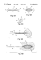
- FIG. 5A shows a side view of a mesh tube implant in its low profile first configuration
- FIG. 5B shows a side view of a mesh tube implant in its large profile second configuration
- FIG. 5C shows a detailed view of the band of the mesh tube embodiment
- FIG. 6A shows a side view of the mesh tube embodiment in its low profile. first configuration being delivered into a tissue location
- FIG. 6B shows a sectional illustration of the mesh tube implant its large profile, second configuration residing within tissue
- FIG. 7A shows a perspective view of a rolled tube implant in its small profile first configuration
- FIG. 7B shows a perspective view of the rolled tube implant in its large profile second configuration
- FIG. 8A is a side view of a sheet of material used to form the rolled tube implant
- FIG. 8B shows an end view of a sheet of material used to form the rolled tube implant
- FIG. 9A is a side view and partial cut-away view of the rolled tube implant being delivered to a tissue location through a delivery device;
- FIG. 9B is a cross-sectional view taken along the line 9 A- 9 B of FIG. 9A;
- FIG. 9C is a side view illustration of the rolled tube implant placed within tissue and expanded into its second configuration
- FIG. 9D is a cross-sectional view of the rolled tube implant viewed along the line 9 D in FIG. 9C;
- FIG. 10A is a perspective view of an implant comprising a spine and plurality of rings in its small profile first configuration
- FIG. 10B is a perspective view of the implant comprised of a spine and plurality of rings in its large profile second configuration
- FIG. 11A is a side view of the implant comprised of a spine and plurality of rings in its low profile, first configuration being delivered to a tissue location;
- FIG. 11B is a cross-sectional view of the implant comprised of a spine and a plurality of rings viewed along the line 11 B— 11 B in FIG. 11A;
- FIG. 11C is a section side view of the implant comprised of a spine and plurality of rings in its large profile, second configuration placed within tissue;
- FIG. 11D is a cross-sectional view of the implant comprised of a spine and a plurality of rings viewed along the line 11 D— 11 D in FIG. 11C;
- FIG. 12A is a side view of a bifurcated implant in its low profile first configuration
- FIG. 12B is a front view of a bifurcated implant in its low profile first configuration
- FIG. 12C is a side view of a bifurcated implant in its large profile second configuration
- FIG. 12D is a front view of a bifurcated implant in its large profile second configuration
- FIG. 13 is a side view of an alternate bifurcated implant having a slanted piercing edge in its low profile first configuration
- FIG. 14A is a side view of a bifurcated implant in its low profile. first configuration being delivered to a tissue location;
- FIG. 14B is a sectional side view of a bifurcated implant in its large profile, second configuration placed within tissue;
- FIG. 15A is a top view of a bifurcated open spring implant in its low profile first configuration
- FIG. 15B is a top view of a open spring bifurcated implant in its large profile second configuration
- FIG. 15C is a side view of an open spring bifurcated implant in its low profile first configuration
- FIG. 15D is a side view of an open spring bifurcated implant in its large profile second configuration
- FIG. 16A is a side view of an open spring bifurcated implant being delivered to a tissue location
- FIG. 16B is a sectional side view of an open spring bifurcated implant located within tissue and expanded to its large profile second configuration
- FIG. 17A is a top view of a bifurcated spine and hoop implant in its low profile first configuration
- FIG. 17B is a top view of a bifurcated spine and hoop implant in its large profile second configuration
- FIG. 17C is a side view of a bifurcated spine and hoop implant in its low profile first configuration
- FIG. 17D is a side view of a bifurcated spine and hoop implant in its large profile second configuration
- FIG. 18A is a side view of a bifurcated spine and hoop implant in its low profile, first configuration being delivered to a tissue location;
- FIG. 18B is a sectional side view of a bifurcated spine and hoop implant placed within tissue and expanded to its large profile second configuration;
- FIG. 19A is a side view of a flexible brush implant.
- FIG. 19B is an end view of the flexible brush implant.
- FIG. 19C is a side view of the flexible brush implant at its post delivery configuration.
- FIG. 19D is a side view of a flexible brush implant having a core formed of twisted wires
- FIG. 19E is a section view of the flexible brush implant show in FIG. 19D;
- FIG. 19F is a partial cut-away view of the flexible brush implant and associated delivery system penetrating the intended tissue location
- FIG. 19G is a partial cut-away view of an implanted flexible brush implant and its associated delivery system being withdrawn.
- FIGS. 1A and 1B show a first embodiment of the implant comprising a helical coil spring 10 .
- the spring is formed from a filament 12 of flexible material such as stainless steel or other metal or high density polymer.
- the filament is helically wrapped to form several individual coils 14 that comprise a spring having an interior 15 .
- the filament 12 terminates with a small tab 18 extending in a plane parallel to the axis of the implant.
- the tabs 18 are used for maintaining the implant upon the delivery device as will be described in further detail below.
- FIGS. 1C and 1D show an alternative spring implant embodiment 26 comprised of two segments 27 that are wound in opposite directions and joined together by a bridge 29 . Each segment has a free end 30 in which the filament 12 terminates in a bulbous tab 18 .
- the spring implant embodiments are easily arranged from a first configuration to a second configuration, where the second configuration of the implant has a larger profile than that presented while in the first configuration.
- Profile may be defined as the maximum width, or in the case of a coil, the diameter, of the device.
- FIGS. 1A and 1C show the device in a small profile, first configuration that is suitable for delivery of the device into the tissue.
- FIGS. 1B and 1C show the implant devices in a larger profile, second configuration into which the implant is transformed after delivery to place surrounding tissue in stress.
- the spring In its first configuration, shown in FIGS. 1A and 1C, the spring is wrapped more tightly, having a longer length L 1 and more coils 14 and thus a smaller diameter D 1 than in the second configuration shown in FIGS. 1B and 1D.
- the diameter D 2 In the second configuration, shown in FIGS. 1B and 1D, the diameter D 2 is greater than D 1 and L 2 is less than L 1 because the spring has expanded, becoming less tightly wound and having fewer coils 14 .
- the alternate, double spring embodiment resiliently expands from its restrained first configuration to its larger profile, second configuration more gradually than does the single spring implant 10 .
- the counter rotation of the oppositely wound spring segments 28 serves to slow the unwinding of the device, thereby providing control over the magnitude of injury experienced by the surrounding tissue.
- the implant is more easily delivered into the intended tissue location while in the first configuration of FIGS. 1A and 1C.
- the reduced profile presented by the spring in a smaller diameter D 1 can more easily penetrate tissue.
- a channel need not be preformed by removing tissue through coring or laser techniques to place the implants.
- the implants are not intended to maintain a patent channel through the subject tissue through which blood can flow.
- the implants of the present invention induce angiogenesis by interacting with the tissue and blood already in the area into which they are placed.
- the expansion of the implant to its larger profile, second configuration serves not only to help anchor the implant within the tissue, but also serves to irritate and injure the surrounding tissue into which it is implanted.
- the spring embodiments are fabricated to have an unstressed configuration equivalent to the second configuration shown in FIGS. 1B and 1D as this will be the final implanted configuration of the device after release from its delivery device.
- the expanding implants may rupture and push aside tissue, which permits the inflow and collection of blood from the surrounding area. However, maintaining a patent channel for blood flow through the implant is not necessary.
- a more important aspect of the presence of the implants is that injury response exhibited by the surrounding ischemic tissue is maximized and angiogenesis is initiated by the resulting thrombosis and fibrin growth as described above.
- the implants remain expanded against the surrounding tissue after implantation becoming clotted with thrombosis and fibrin growth throughout the implant structure. After the new tissue has surrounded and ingrown the implant new vessel growth will emerge in the region to supply the new tissue. At this advanced stage of injury response and healing, the stress applied on surrounding tissue by the expanded implant may be minimal or nonexistent because tissue has grown around and accommodated the implant.
- FIGS. 2A-2C A percutaneous delivery device for delivering the implants to the myocardium of the heart is shown in FIGS. 2A-2C.
- FIG. 3 shows a diagrammatic sectional view of the left ventricle 2 of a human heart 1 into which the delivery device gains access.
- Each of the implant embodiments described herein may be delivered percutaneously through a delivery catheter 36 , shown in FIGS. 4A-4D, as will be described in detail below. It is noted that, throughout the description of the implant embodiments and their associated delivery systems, “proximal” refers to the direction along the delivery pathway leading external to the patient and “distal” refers to the direction along the delivery pathway internal of the patient.
- a guide catheter (not shown) is first navigated through the patient's vessels to reach the left ventricle 2 of the heart 1 .
- a barb tipped guidewire 34 may then be inserted through the guide catheter and into the ventricle where it pierces the myocardium 4 and becomes anchored within the tissue.
- a steerable implant delivery catheter 36 may be advanced over the guidewire to become positioned within the ventricle for delivery of the implants.
- the guidewire lumen of the delivery catheter 36 may be eccentrically located on the catheter 36 . Therefore, when the catheter is rotated about the guidewire, the center of the catheter will rotate through a circular path as demonstrated in FIGS.
- the outside diameter of the delivery catheter is preferably less than 0.100 inch.
- the delivery catheter may be provided with steering capability by means of a pull wire extending the length of the catheter and attached at its distal end such that pulling on the wire from the proximal end causes the distal tip of the catheter to be deflected. Steering capability thus provides a broader range of delivery area with a single catheterization.
- FIGS. 2A and 2B show the delivery of the spring implant 10 into tissue.
- the implant may be carried to the delivery location over a flexible push tube 20 that is slidable through the steerable delivery catheter 36 .
- FIG. 2C shows the alternate embodiment of the spring implant 26 mounted on the push tube 20 .
- the push tube over which the spring implants are carried may be an elongate flexible hypodermic tube and be configured to have a sharp distal end 22 for piercing the surface of tissue into which the implant will be placed. Additionally, the push tube slidably receives a release wire 21 , which extends through thread loops 24 that pass through side holes 25 at the distal end of the push tube 20 and wrap around tabs 18 of the spring.
- a thread loop 24 extends from the release wire, through a side hole to capture the bridge 29 as well.
- the ends 16 of the spring are held close to the push tube 20 to maintain a tightly wrapped diameter, extended length, first configuration during delivery of the device into the tissue.
- the tabs 18 preferably have a bulbous configuration of greater diameter than the filament 12 to prevent the tabs from slipping through the thread loop.
- the push wire 20 After being advanced through the delivery catheter 36 which has been placed adjacent tissue to be treated, the push wire 20 is advanced distally, independently of the delivery catheter 36 , so that the sharp distal tip 22 pierces the tissue, as shown in FIG. 2 A. Continued further distal movement of the push wire 20 advances the implant into the tissue where it can be released to assume its second configuration having a greater profile than the first configuration.
- the depth to which the implant is placed within the tissue is not believed to be a significant factor in the ultimate success of the device, however, placement within the tissue within an area believed to have the most significant amount of vascular activity is desirable.
- release wire 21 is withdrawn proximally relative to the push tube 20 .
- Thread loops become released from the wire 21 and are free to pass through side holes 25 as the spring resiliently expands to its second, large profile configuration, within the tissue.
- the greater profile and increased diameter of the implant in the second configuration puts an immediate stress on the surrounding tissue causing some tearing.
- the surrounding tissue 4 may tend to herniate into the implant device at herniation points 28 located between the coils 14 of the implant.
- the push tube 20 is withdrawn proximally through the interior 15 of the implant and back into the delivery catheter 36 together with the release wire, and the assembly withdrawn from the patient.
- the thread loops 24 preferably absorbable suture material, may be left behind, attached to the implant.
- implants 8 may be placed within a region of ischemic tissue as shown in FIG. 3 .
- the implants 8 generally expand to a diameter of approximately 2 mm and are preferably spaced so that each implant serves an area of one square centimeter.
- the density of approximately one per square centimeter is preferred so as not to interfere with the muscular function of the tissue to which they are implanted. In other words, many implants within a certain area could potentially interfere with the motion of the muscle tissue to the detriment of other necessary functions of that tissue.
- Multiple implants are delivered to a given tissue location by repeating the steps recited for delivering a single implant.
- the implants induce angiogenesis within the surrounding tissue 4 by other mechanisms.
- One such mechanism is a process of thrombosis of the blood surrounding an implanted device 10 and being permitted to pool within the interior 15 of the device. Blood that pools around the implant or in the implant thrombosis which leads to fibrin growth and nucleation of arterioles that become vessels to supply blood to the healed region.
- This process may be further enhanced by application of an angiogenic substance to the implant device.
- the substance may be a solid or fluid placed within the interior 15 of the device before or after delivery of the implant so that it comes into contact with and is distributed by blood entering and surrounding the implant.
- the delivery device may be configured as a conduit through which the substance can be transmitted and released into the implant while the delivery device and implant are still associated.
- the angiogenic substance may be advanced from the proximal end of the tube, outside the patient, through the lumen of the tube and expelled from a port at the distal end of the tube and into or around the implanted device.
- the angiogenic substance may be coated onto the device or the device may be made from such a substance.
- FIG. 5A Another embodiment of the vascular inducing implants is shown in FIG. 5A.
- a mesh tube implant 40 is shown in its low profile first configuration, suitable for delivery into tissue.
- the mesh tube is comprised of a mesh pattern of wire like elements 42 that are formed from a material that is flexible yet sufficiently rigid to maintain an expanded, second configuration having a larger profile than its first configuration.
- the mesh tube embodiment may be fabricated from a thin metal sheet etched out a pattern of spaces or openings and then rolled and the ends joined to form a tube.
- the implant may be formed from a fabric such as dacron rolled into a tubular shape.
- the braided tube is formed from wire elements 42 woven together to form a tube with the elements slidable relative to each other.
- the mesh may be resiliently expandable, remaining expanded by the inherent resilience of the material selected, such as highly elastic or high tensile strength material.
- the mesh tube may be plastically deformed to its second configuration, if the elements are formed from a malleable alloy
- the wire ends 46 are joined to rings 44 .
- the ends 46 of the wire elements 42 may be joined to the end ring 44 at connections 48 .
- the rings 44 may be polymer tubes heat shrunk to the element ends to form the connections.
- the rings may be stainless steel, connected to the elements by solder joints.
- the elements may be fabricated to be movable relative to the ring 44 .
- the ends 46 of the elements may be formed to have eyelets that are threaded around a narrow end ring 44 . Thus, the elements would be free to adjust their position along the ring during expansion from the first to the second configuration. Additionally, as shown in FIG.
- the ring 44 may be non-continuous, having a split 50 across its surface to promote expandability. In this configuration, the ring 44 may provide the supporting force to keep the implant in its expanded second configuration.
- the split 50 in the ring 44 permits the ring to be coiled into a small configuration for delivery, yet expand and uncoil into a larger configuration.
- the ring 44 may be resiliently expandable, whereby its natural tendency is to have an uncoiled configuration and maximum diameter.
- the ring is confined in a coiled smaller diameter during delivery to the intended tissue location and is released to uncoil and resiliently expand to its larger configuration once placed in the tissue.
- the elements 42 join to the rings 44 at both ends of the mesh tube embodiment thus slide into the second, larger profile configuration under the force of the resilient rings 44 .
- the rings 44 may be plastically deformable so that they expand along with the movement of the elements 42 of the mesh tube 40 as the length of the tube is compressed to cause radial expansion.
- the mesh tube implant may be delivered over a delivery system comprising a relatively stiff small diameter tube 52 , such as a hypotube having slidable within its central lumen a piercing release wire 54 as shown in FIGS. 6A and 6B.
- a relatively stiff small diameter tube 52 such as a hypotube having slidable within its central lumen a piercing release wire 54 as shown in FIGS. 6A and 6B.
- the mesh tube 40 is supported from longitudinal movement at its proximal end 56 by a stop 60 mounted on the exterior of the hypotube 52 .
- the distal end 58 of the mesh tube is supported from longitudinal movement by a small catch member 62 mounted on the exterior of the release wire 54 . Both the catch 62 and the stop 60 engage the rings 44 at the proximal and distal ends of the mesh tube 40 .
- the hypotube 52 and release wire 54 carrying the mesh tube 40 are delivered to the intended tissue location through a previously placed steerable catheter 36 as was described in connection with FIGS. 2A and 2B.
- the steerable delivery catheter 36 is not shown in FIGS. 6A and 6B but is understood to be part of the delivery system. While tension is applied on the mesh tube by placing slight pressure on the release wire 54 in the distal direction and maintaining pressure on the hypotube 52 in the proximal direction, the mesh tube is maintained in its low profile extended length first configuration. The combination is together moved distally toward the intended tissue location.
- the sharp piercing distal tip 64 of the release wire 54 penetrates the endocardial surface 6 to provide access to the myocardium 4 .
- the mesh tube After placement of the mesh tube within the myocardium 4 , it is expanded to its second configuration by moving the hypotube, which engages the proximal end 56 of the tube, in a proximal direction while moving the catch 62 on the release wire 54 in a proximal direction.
- the ends 58 and 56 of the mesh tube are moved closer, thereby shortening the length of the tube and causing it to expand radially, placing stress on the surrounding myocardial tissue 4 .
- the release wire 54 After expansion of the mesh tube, the release wire 54 may be withdrawn proximally so that its piercing distal tip 64 is within the hypotube 52 . The combination can then be withdrawn from the patient without risk of injury to vessels from the sharp tip during withdrawal.
- FIGS. 7A and 7B show yet another embodiment of the vascular inducing implant comprising a resiliently expandable rolled tube 70 .
- the rolled tube may be fabricated from a flat sheet 72 , as shown in FIGS. 8A and 8B.
- the material is preferably flexible, but will maintain a resilient energy after being bent into a tubular shape tending to maintain the tube in a relatively expanded, large diameter configuration.
- a metal such as stainless steel or a high density polymer is a preferred material.
- the tube material may be a solid or may be porous such as a mesh screen.
- the flat sheet is preferably configured to have formed along one longitudinal edge 76 a tubular ridge 78 that will serve as a lock for holding the sheet in a tubular configuration while being delivered to the tissue location, as will be described in further detail below.
- the tubular ridge 78 may be a separate tubular segment that is attached to the flat sheet 72 by bonding such as adhesive, soldering or welding. Alternatively the tubular ridge may be formed by curving over a longitudinal edge 72 of the sheet to define a tube along that edge.
- the flat sheet into the low profile first configuration requires rolling the flat sheet 72 into a tightly wound roll to define the cylindrical structure of the tubular implant 70 .
- the rolled tube may be coiled upon itself several times to form a small outer diameter D 1 as shown in FIG. 7 A. Force is required to maintain the rolled tube implant in the first configuration because the elastically deformed sheet material 72 naturally tends to the larger diameter D 2 of the second configuration shown in FIG. 7 B.
- the rolled tube is implanted in the tissue in the first configuration shown in FIG. 7 A and permitted to expand to its equilibrium configuration represented in FIG. 7B having a larger profile (diameter) than the first configuration.
- the expansion of the rolled tube within the subject tissue creates slight injury to the tissue surrounding the implant as well as provides a device for interacting with blood from the surrounding tissue to initiate the process of angiogenesis as was described above.
- a rolled-tube formed from a porous or mesh material further injury to the tissue which surrounds the implant is expected due to the rough surface of the implant material and constant dynamic contact with the tissue.
- the porous or mesh material may enhance fibrin growth through the device to further enhance angiogenesis.
- FIGS. 9A and 9B Delivery of the rolled tube embodiment 70 is shown in FIGS. 9A and 9B.
- the rolled tube embodiment may be delivered to the subject tissue percutaneously, thoracically or surgically by a cut-down method.
- percutaneous delivery is preferred because it is least invasive and traumatic to the patient.
- FIGS. 9A-9D depict delivery of the rolled tube implant percutaneously to the myocardial tissue 4 of the heart.
- the delivery catheter is anchored in position adjacent the intended tissue location by a barbed tip guidewire 34 that extends through an eccentric guidewire lumen 32 of the delivery catheter.
- the barbed tip guidewire is anchored in the myocardial tissue 4 .
- the rolled tube 70 is carried through the central lumen 38 of the delivery catheter 36 over a coaxial arrangement of a push tube 80 and piercing wire 82 having a piercing distal tip 84 .
- the piercing wire 82 is longitudinally slidable with respect to the push tube 80 so that it may be extended relative to the push tube to release the rolled tube as will be described below.
- the push wire has formed along its length a backstop 86 configured as a disk radially extending from the push tube to provide surface against which the proximal end 88 of the rolled tube can abut during delivery.
- the backstop may additionally have two longitudinally and distally extending protrusions 90 and 92 .
- the inner protrusion 90 extending within the interior of the tubular ridge 78 , which is arranged to be at the edge of the outermost coil 93 of the rolled tube during delivery.
- the outer protrusion 92 holds the outermost coil 93 from its outer surface, working in conjunction with the inner protrusion to maintain the tube in its small diameter first configuration against the resilient expansive force inherent in the rolled tube.
- the distal end 94 of the rolled tube is supported in its compact first configuration by a proximally and longitudinally extending protrusion 96 which resides in the interior 79 of the tubular ridge 78 at the distal end 94 of the rolled tube.
- the protrusion 96 extends proximally from the sharpened distal end 84 of the piercing wire 82 .
- the rolled tube located between the protrusions 90 , 92 at the proximal end 88 and piercing wire 82 extending through its interior 74 .
- the protrusion 96 extends proximally, back into the interior 74 of the tube.
- the push tube, piercing wire and rolled tube combination is advanced, together, distally out of the distal end of the delivery catheter 36 as shown in FIG. 9B so that the piercing distal tip 84 of the piercing wire penetrates the surface of the tissue 6 .
- the assembly is advanced distally into the tissue 4 to a depth that receives the entire implant as shown in FIG. 9 D.
- the proximal end 88 of the implant may, but need not be flush with the surface 6 of the tissue 4 .
- the piercing wire 82 is moved distally and the push tube 80 is moved proximally, in opposite directions relative to each other, so that the backstop 86 and protrusions 90 , 92 and 96 move away from the ends of the tube, releasing it from the confined, first configuration so that it expands to its second, larger profile configuration shown in FIGS. 9C and 9D.
- the piercing wire is withdrawn proximally through the interior 74 of the now expanded rolled tube 70 into the push tube 80 , which is then withdrawn into the delivery catheter 36 .
- the barbed tip guidewire 34 is then pulled from its anchored location within the tissue 4 and the entire delivery catheter 36 is withdrawn from the patient.
- FIG. 10A shows another embodiment of the vascular inducing implants.
- a spine implant 100 is comprised of a plurality of expandable c-shaped rings 102 concentrically arranged along an axial support or spine 104 . Each ring is joined to the spine at a point along their circumference. The spine is tangent to each ring 102 , with each ring lying in a plane that is normal to the axis of the spine.
- a discontinuity 106 at the top of each ring permits the rings to expand between two configurations: a first, low profile configuration in which the ends 108 of the ring overlap to define a ring of relatively small diameter and a second configuration that presents a larger profile, in which the leaves of the ring are open and do not overlap defining a larger diameter and profile.
- the spine implant embodiment may be a unitary structure formed from an elastically deformable material such as a plastic or stainless steel.
- the rings 102 may be separate components that are adjoined to the spine by welding, soldering or bonding.
- the ends of each ring are preferably formed to have eyelets 110 .
- An elongate release pin 112 shown in phantom in FIG. 10A, may be inserted through the aligned eyelet pairs of all the closed rings on the spine.
- the pull pin 112 may be inserted through the eyelets to maintain the rings 102 in a closed configuration by maintaining each ring 102 in a closed configuration, with the eyelets 110 aligned concentrically.
- the rings 102 may be expanded after implantation within the tissue by pulling the pin from the eyelets to release the rings and permit resilient expansion as will be described in further detail below.
- FIGS. 11A-11D illustrate the delivery of the spine implant 100 .
- FIGS. 11A and 11B show the implant in its first, low profile configuration, which is maintained during deliver and insertion into the intended tissue location.
- the implantation of the device will be described as it is implanted into myocardial tissue of the heart.
- the device may be delivered by a variety of methods including surgically or thoracically, the preferred method of delivery is percutaneous, accessing the myocardium 4 through the left ventricle of the heart as is shown in FIGS. 4A-4D.
- the spine implant 100 is delivered over a push wire 114 that is slidable through the delivery catheter 36 .
- the push wire extends through the center of the rings during delivery while they are in their closed, small profile configuration.
- the push wire 114 may be of a diameter which is approximately the same size as the inside diameter of the rings in their closed, small profile configuration to remove any slack between the implant and the push wire during delivery.
- the pull pin 112 extends through the eyelets 110 and is parallel with the push wire 114 through the delivery catheter 36 where it can be manipulated independently of the push wire at its proximal end extending outside the patient.
- the push wire 114 has a sharpened distal end 118 that is capable of piercing the tissue surface 6 to provide an entry site into which the implant may be inserted into the tissue 4 .
- either the pull pin 112 or the push wire 114 may have formed on its surface a backstop against which the most proximal ring 102 can abut to resist distal movement.
- the pull pin 112 may be pulled proximally to be removed from the eyelets of the rings 110 permitting them to resiliently expand to the open configuration as shown in FIGS. 11C and 11D.
- the push wire 114 may be withdrawn proximally through the center of the rings and out of the tissue and the delivery device withdrawn from the patient.
- FIGS. 12A-12D show another embodiment of the implant device having a first configuration that is uniaxial and a second configuration in which a portion of the device becomes biaxial or bifurcated.
- the bifurcated implant 120 is preferably a hollow unitary structure essentially comprised of three tubular sections arranged similar to a pair of pants.
- the implant has a trunk portion 122 having a generally tubular configuration which splits into a first leg 124 and a second leg 126 , each about one-half the diameter of the trunk portion and having a length that is approximately one-half the length of the entire implant.
- the legs 124 and 126 are closed, their longitudinal axes lying parallel to the central axis of the trunk portion 122 .
- the implant 120 presents a low profile suitable for penetration and delivery into tissue.
- FIGS. 12C and 12D show the implant in its second, large profile configuration wherein the legs 124 and 126 are split apart; curved away from each other such that their axes approach an angle of 90° relative to the central axis of the trunk portion 122 .
- the split legs of the implant serve to stress and injure surrounding tissue into which the implant has been inserted.
- the tearing and abrasion of the tissue surrounding the now expanded legs 124 and 126 respond to the injury through a healing process that leads to angiogenesis as described above.
- the tissue continues to be irritated by the presence of the implant, thereby continuing the injury response and initiation of angiogenesis.
- FIG. 13 shows a variation of the biaxial implant 120 having a slanted profile edge 130 formed along the ends of the legs 124 and 126 to help to facilitate penetration through the tissue.
- the blunt edge tubular ends of the legs 124 and 126 as shown in FIGS. 12A-12D may be suitable for penetrating soft tissue
- the angled edge 130 shown in FIG. 13 provides a sharper profile to pierce tough layers of tissue.
- the angled edge may be configured in many ways other than the sloping edge shown in FIG. 13 .
- the second leg 126 may have an edge that is angled in the reverse direction from the edge of leg 124 to form an arrowhead profile (not shown).
- the biaxial implant may move from its first, compact profile configuration to its second, expanded profile configuration either by inherent resiliency of the implant material, or by a plastic deformation.
- a splitting force may be applied between the legs of the implant once it has been inserted into tissue.
- the splitting force may be applied by a pull wire extending through the interior of the implant, having a large profile distal tip that runs between the adjoining legs as the pull wire is moved in a proximal direction and removed from the center of the implant through the trunk portion.
- the implant is resiliently expandable and may be delivered and expanded to the extended tissue location over two guidewires as is described in detail below.
- FIGS. 14A and 14B illustrate the delivery of the bifurcated implant embodiment into tissue such as myocardial tissue 4 of the myocardium.
- the bifurcated embodiment is preferably delivered percutaneously to the myocardium through a steerable delivery catheter 36 that has been inserted into the left ventricle of the heart adjacent the myocardial tissue to receive the implant.
- the bifurcated implant 120 is carried through the delivery catheter 36 over a guide tube 132 sized to fit closely the inside diameter of the trunk portion 122 of the implant.
- Through the guide tube 132 extends two support wires 134 and 136 that extend through the trunk portion of the implant and into the legs 124 and 126 during delivery.
- the support wires 134 , 136 are relatively stiff to maintain the legs 124 , 126 in their joined, low profile first configuration as shown in FIG. 14 A.
- the wires and guide tube are slidable relative to each other and through the delivery catheter 36 .
- the guide tube extends into the interior of the implant only through the trunk portion 122 .
- the support wires 134 , 136 extend distally beyond the trunk portion and into each leg to act as stiffening members, providing axial support from the inside diameter of each leg to resist the resilient force of the legs to bend apart from each other.
- the entire assembly is moved distally, with the guide tube 132 and wires 134 , 136 being pushed distally to expose the implant from the distal end of the delivery catheter 36 so that it may penetrate the endocardial surface 6 and enter the myocardium 4 as shown in FIG. 14 B.
- the delivery force pushing the implant in the distal direction is applied by the distal end of the guide tube 132 engaging the junction of the legs 138 .
- the support wires 134 and 136 are withdrawn proximally from the legs 124 , 126 of the implant permitting them to expand apart from each other to injure the surrounding tissue and place it in a stressed condition that will be maintained by the implant in its second configuration.
- the expanded implant serves to resist migration out of the tissue despite tissue movement because the implant has clawed into the tissue during expansion.
- the guide tube 132 and support wires 134 , 136 are withdrawn further proximally, into the delivery catheter 36 , which then may be withdrawn from the patient.
- FIGS. 15A-15D Another embodiment of a bifurcated implant is shown in FIGS. 15A-15D.
- the open spring bifurcated implant 140 is intended to have a trunk portion 142 and two leg portions 144 and 146 similar to the bifurcated embodiment discussed above.
- the open spring bifurcated embodiment may comprise two helically wrapped coil springs 148 , 150 joined together only at the proximal end 152 of the trunk portion.
- the bifurcated spring embodiment may comprise a single spring that is wound to double back upon itself at the proximal trunk coil 152 and defining two legs 144 and 146 extending therefrom that are defined by each end of a single spring.
- the coil spring should be flexible and capable of maintaining substantially its expanded bifurcated and larger profile configuration under the collapsing force of the stressed tissue in which it is implanted.
- FIGS. 15A and 15C The first, low profile configuration of the implant is shown in FIGS. 15A and 15C.
- the coils 152 of each of the legs 144 and 146 interleave so that they substantially lie along the same longitudinal axis as the trunk portion 142 .
- the overall profile of the implant 140 is minimized, facilitating delivery of the implant into tissue.
- FIGS. 15B and 15D show the implant in its larger profile second configuration.
- the free ends of each of the legs 144 and 146 spring open, naturally inclined to the Y-shape bifurcated configuration, because they are plastically deformed to have that shape during their formation.
- the profile of the implant is increased by the movement of the leg portions away from the axis of the trunk portion 142 .
- the expanding leg portions When permitted to expand within the subject ischemic tissue, the expanding leg portions are expected to cause some minimal injury and possible tearing of the tissue into which it is implanted.
- the injury which will be continually irritated by the presence of the implant in its second configuration, is expected to instigate a healing response by the tissue that will initiate angiogenesis by the mechanisms described above.
- FIGS. 16A and 16D illustrate the steps of delivering the bifurcated open spring implant into ischemic tissue 4 .
- the implant is maintained in its uniaxial, low profile first configuration by a relatively stiff piercing wire 158 having a sharpened distal tip 160 for piercing the surface of the tissue 6 .
- the piercing wire 158 extends through the interior 162 of the spring embodiment, retaining the coils 154 of the legs 144 and 146 along the central axis by contacting their inside surfaces. The legs are held against movement by the presence of the wire 158 .
- the sharpened tip 160 of the piercing wire protrudes from the distal end of the implant so that it will be first to contact the tissue during distal movement to the implant site.
- Push tube 156 is slidable over the push wire and has a larger diameter than the push wire, sized to engage the circumference of the most proximal coil 152 of the implant.
- the push tube delivers a pushing force against the implant during insertion into the tissue, when both the piercing wire 158 and push tube 156 are moved distally in unison to maintain the piercing wire through the implant which is maintained in its first configuration.
- the push tube 156 can move independently of the piercing wire 158 , so that once the implant has been delivered to a proper depth within the tissue 4 , the piercing wire 158 may be retracted into the push tube as shown in FIG. 16B, to release the coils 154 to their expanded second configuration. After delivery and release of the implant into the ischemic tissue, the push tube 156 and piercing wire 158 may be retracted proximally into the steerable delivery catheter 36 and the entire assembly withdrawn from the patient.
- FIGS. 17A-17D show a variation of the open spring bifurcated implant embodiment.
- the bifurcated loop implant 170 is comprised of first and second spines 172 , 174 each having a plurality of circular loops 176 .
- the loops 176 are joined to the respective spines at a point around their circumference such that they are arranged substantially concentrically.
- the spines 174 , 172 share several common loops 176 in a trunk portion 178 of the implant.
- the free ends of the spines 172 , 174 form leg portions 180 , 182 of the implant, respectively.
- the implant is shown in its first low profile configuration in FIGS. 17A and 17C.
- the loops 176 of both spines and the trunk portion are interleaved and lie substantially along the same longitudinal axis.
- the leg portions 180 and 182 spring apart under the resilient force of the spines 172 and 174 which are preformed to have a curved configuration, yielding the large profile configuration shown in FIGS. 17B and 17D.
- the implant is delivered into the subject ischemic tissue 4 by the steps discussed above in connection with the open spring bifurcated embodiment and which are illustrated in FIGS. 18A and 18B.
- the piercing wire and push tube 158 , 156 may be used to deliver the loop bifurcated implant 170 in the same manner as the open spring embodiment described above.
- a brush implant 240 is comprised of a central core member 242 having a plurality of resilient bristles 244 extending radially therefrom to irritate surrounding tissue.
- the bristles 244 of the brush 240 collapse against the core 242 during distal movement into the tissue during delivery to define a low profile fist configuration.
- the bristles resiliently expand in a radially outward direction, with respect to the core, to define a larger profile second configuration that irritates and places stress on surrounding tissue.
- the central core member 242 is preferably somewhat rigid to facilitate insertion into the tissue 4 .
- the core may be solid or a hollow tube to define a central lumen 246 over which the implant can be delivered into the intended tissue location. Additionally, the central lumen 246 may contain an angiogenic substance to be delivered to the intended tissue location along with the implant.
- the core 242 of the brush implant may be comprised of several wires helically wrapped around each other along a single axis as shown in FIGS. 19D and 19E.
- the brush implant shown in FIG. 19D is comprised of three helically wrapped wires 248 , 250 and 252 defining the core 242 . Wedged in between the wrapped wires are bristles 244 which extend radially from the core 242 .
- the three helically wrapped wires define a central opening 254 through the center of the core.
- the central opening may be useful for holding an angiogenic substance or thrombus of blood within the implant that will later interact with blood flow after implantation.
- the central opening 254 may receive a guidewire so that the implant may be delivered to its intended location by tracking over the guidewire that has been inserted into a patient.
- the core 242 may be formed from only two separate wires that are helically wrapped about each other; however, a central opening 254 may not be substantially defined by only two wires.
- the bristles 244 attached to the core 242 serve injure and irritate surrounding tissue into which it is implanted to cause an injury response that leads to angiogenesis.
- the bristles resiliently extend from the core in a radially outward direction to place stress on surrounding tissue and cause irritation.
- the bristles provide a plurality of contact points with the surrounding tissue where irritation occurs, providing a plurality of nucleation sites where angiogenesis can be initiated.
- Tubes may be used in place of the wires that form the core 242 and also the bristles 244 .
- Tubular bristles and core wires provide lumens that can retain a quantity of an angiogenic substance or thrombi of blood intended to interact with the surrounding tissue into which the device is implanted.
- the core wires may have an outside diameter of 0.008 inch and the bristles may have an outside diameter on the order of 0.006 inch to 0.010 inch.
- the bristles may be made from stainless steel or plastic.
- the brush implant may be delivered percutaneously, thoracically or surgically via a cut-down method to the intended tissue location.
- FIG. 19F represents the brush implant being delivered percutaneously into the myocardium 4 .
- a suitable delivery system for the brush type implant may include a steerable outer catheter 36 within which a slidable smaller diameter brush carrier catheter 260 having a central lumen 262 . The distal end 264 of the brush carrier catheter is sharpened to be capable of piercing the endocardial surface of the myocardium 8 .
- a brush implant 240 is pushed through the central lumen 262 of the catheter 260 in a distal direction by a push wire 266 that is also sized to fit within a central lumen of the catheter. Therefore, to deliver a brush implant into tissue, the distal end of the steerable catheter 36 is brought in proximity to the intended tissue location as shown in FIGS. 19F and 19G.
- the brush carrier catheter carrying a brush implant 240 and push wire 266 within its central lumen 262 is navigated distally through the steerable catheter and out its distal end so that the sharpened distal end 264 of the catheter will pierce the surface of the tissue to permit delivery of the implant.
- the push wire 266 is moved distally to push the brush implant 240 out of the distal opening 268 of the catheter 260 .
- the distal end of the brush carrier catheter 264 need not be sharpened to pierce the tissue implant location. Rather, the brush implant itself may have a sharpened distal tip 270 formed by the wrapped wires or hypotube of the core 242 that is capable of penetrating the tissue 4 with pushing force provided from the push wire 266 .
- the push wire 266 and brush carrier catheter 266 may be withdrawn proximally back into the steerable catheter 36 and the implant system 258 withdrawn from the patient.
- the distal movement through the tissue that occurs during implantation causes the bristles 244 to maintain an acute angle with a longitudinal axis of the brush implant, pointing in the proximal direction.
- the bristles tend to resiliently return to a radially outward extending position that places stress on the surrounding tissue and causes irritation. Additionally, the bristles act as barbs to prevent proximal migration of the implant.
- the invention provides an implant and delivery system for promoting angiogenesis within ischemic, viable tissue.
- the invention is particularly advantageous in promoting angiogenesis with an ischemic myocardial tissue of the heart.
- the implants are simple and readily insertable into the intended tissue location with a minimum of steps.
- the delivery systems are simple to operate to implant the devices quickly and safely.
Landscapes
- Health & Medical Sciences (AREA)
- Life Sciences & Earth Sciences (AREA)
- Engineering & Computer Science (AREA)
- Biomedical Technology (AREA)
- Veterinary Medicine (AREA)
- Public Health (AREA)
- Cardiology (AREA)
- General Health & Medical Sciences (AREA)
- Heart & Thoracic Surgery (AREA)
- Animal Behavior & Ethology (AREA)
- Transplantation (AREA)
- Vascular Medicine (AREA)
- Oral & Maxillofacial Surgery (AREA)
- Surgery (AREA)
- Pulmonology (AREA)
- Gastroenterology & Hepatology (AREA)
- Nuclear Medicine, Radiotherapy & Molecular Imaging (AREA)
- Medical Informatics (AREA)
- Molecular Biology (AREA)
- Prostheses (AREA)
- Surgical Instruments (AREA)
Abstract
Description
Claims (10)
Priority Applications (9)
| Application Number | Priority Date | Filing Date | Title |
|---|---|---|---|
| US09/164,173 US6458092B1 (en) | 1998-09-30 | 1998-09-30 | Vascular inducing implants |
| JP2000571848A JP2002525164A (en) | 1998-09-30 | 1999-09-30 | Flexible implant in the myocardium to promote angiogenesis |
| PCT/US1999/022542 WO2000018325A1 (en) | 1998-09-30 | 1999-09-30 | Flexible transmyocardial implant to induce angiogenesis |
| DE69935075T DE69935075T2 (en) | 1998-09-30 | 1999-09-30 | BENDING TRANSMYOKARDIMPLANTAT FOR THE INDUCTION OF ANGIOGENESIS |
| EP99951643A EP1117352B1 (en) | 1998-09-30 | 1999-09-30 | Flexible transmyocardial implant to induce angiogenesis |
| EP05026330A EP1637083A3 (en) | 1998-09-30 | 1999-09-30 | Flexible transmyocardial implant to induce angiogenesis |
| US09/774,320 US6802858B2 (en) | 1998-09-30 | 2001-01-31 | Vascular inducing implants |
| US09/774,319 US6709425B2 (en) | 1998-09-30 | 2001-01-31 | Vascular inducing implants |
| US10/767,550 US6949117B2 (en) | 1998-09-30 | 2004-01-29 | Vascular inducing implants |
Applications Claiming Priority (1)
| Application Number | Priority Date | Filing Date | Title |
|---|---|---|---|
| US09/164,173 US6458092B1 (en) | 1998-09-30 | 1998-09-30 | Vascular inducing implants |
Related Child Applications (2)
| Application Number | Title | Priority Date | Filing Date |
|---|---|---|---|
| US09/774,320 Continuation US6802858B2 (en) | 1998-09-30 | 2001-01-31 | Vascular inducing implants |
| US09/774,319 Division US6709425B2 (en) | 1998-09-30 | 2001-01-31 | Vascular inducing implants |
Publications (1)
| Publication Number | Publication Date |
|---|---|
| US6458092B1 true US6458092B1 (en) | 2002-10-01 |
Family
ID=22593305
Family Applications (4)
| Application Number | Title | Priority Date | Filing Date |
|---|---|---|---|
| US09/164,173 Expired - Fee Related US6458092B1 (en) | 1998-09-30 | 1998-09-30 | Vascular inducing implants |
| US09/774,320 Expired - Fee Related US6802858B2 (en) | 1998-09-30 | 2001-01-31 | Vascular inducing implants |
| US09/774,319 Expired - Fee Related US6709425B2 (en) | 1998-09-30 | 2001-01-31 | Vascular inducing implants |
| US10/767,550 Expired - Fee Related US6949117B2 (en) | 1998-09-30 | 2004-01-29 | Vascular inducing implants |
Family Applications After (3)
| Application Number | Title | Priority Date | Filing Date |
|---|---|---|---|
| US09/774,320 Expired - Fee Related US6802858B2 (en) | 1998-09-30 | 2001-01-31 | Vascular inducing implants |
| US09/774,319 Expired - Fee Related US6709425B2 (en) | 1998-09-30 | 2001-01-31 | Vascular inducing implants |
| US10/767,550 Expired - Fee Related US6949117B2 (en) | 1998-09-30 | 2004-01-29 | Vascular inducing implants |
Country Status (5)
| Country | Link |
|---|---|
| US (4) | US6458092B1 (en) |
| EP (2) | EP1637083A3 (en) |
| JP (1) | JP2002525164A (en) |
| DE (1) | DE69935075T2 (en) |
| WO (1) | WO2000018325A1 (en) |
Cited By (58)
| Publication number | Priority date | Publication date | Assignee | Title |
|---|---|---|---|---|
| US20030045828A1 (en) * | 1998-01-30 | 2003-03-06 | Wilk Peter J. | Left ventricular conduits to coronary arteries and methods for coronary bypass |
| US6589227B2 (en) * | 2000-01-28 | 2003-07-08 | William Cook Europe Aps | Endovascular medical device with plurality of wires |
| US6620170B1 (en) | 1999-04-26 | 2003-09-16 | C. R. Bard, Inc. | Devices and methods for treating ischemia by creating a fibrin plug |
| US6692458B2 (en) * | 2000-12-19 | 2004-02-17 | Edwards Lifesciences Corporation | Intra-pericardial drug delivery device with multiple balloons and method for angiogenesis |
| US6719805B1 (en) | 1999-06-09 | 2004-04-13 | C. R. Bard, Inc. | Devices and methods for treating tissue |
| US20040082879A1 (en) * | 2000-01-28 | 2004-04-29 | Klint Henrik S. | Endovascular medical device with plurality of wires |
| US20040098105A1 (en) * | 2001-04-26 | 2004-05-20 | Stinson Jonathan S. | Gastric pseudocyst drainage and stent delivery system for use therein |
| US20040147951A1 (en) * | 2002-02-26 | 2004-07-29 | Arvik Enterprises Llc | Removable blood vessel occlusion device |
| US20040172051A1 (en) * | 2003-02-28 | 2004-09-02 | Sundaram Ravikumar | Method and apparatus for tubal occlusion |
| US6786929B2 (en) | 1998-09-30 | 2004-09-07 | C. R. Bard, Inc. | Flexible vascular inducing implants and methods |
| US20050049608A1 (en) * | 2003-06-12 | 2005-03-03 | Aznoian Harold M. | Stent delivery catheter |
| US20050125022A1 (en) * | 2002-03-01 | 2005-06-09 | Sundaram Ravikumar | Blood vessel occlusion device |
| US20060100602A1 (en) * | 2001-01-26 | 2006-05-11 | William Cook Europe Aps | Endovascular medical device with plurality of wires |
| US20070056595A1 (en) * | 2003-04-24 | 2007-03-15 | Mclachlan Craig | Method for treatment of ischaemic tissue |
| US20080221671A1 (en) * | 2000-01-31 | 2008-09-11 | Boston Scientific Scimed | Braided endoluminal device having tapered filaments |
| US7651521B2 (en) | 2004-03-02 | 2010-01-26 | Cardiomind, Inc. | Corewire actuated delivery system with fixed distal stent-carrying extension |
| US20100030319A1 (en) * | 2008-07-31 | 2010-02-04 | Boston Scientific Scimed, Inc. | Coils for vascular implants or other uses |
| US7699884B2 (en) | 2006-03-22 | 2010-04-20 | Cardiomind, Inc. | Method of stenting with minimal diameter guided delivery systems |
| US7704222B2 (en) | 1998-09-10 | 2010-04-27 | Jenavalve Technology, Inc. | Methods and conduits for flowing blood from a heart chamber to a blood vessel |
| US7771463B2 (en) | 2003-03-26 | 2010-08-10 | Ton Dai T | Twist-down implant delivery technologies |
| US7785361B2 (en) | 2003-03-26 | 2010-08-31 | Julian Nikolchev | Implant delivery technologies |
| US20100249815A1 (en) * | 2009-03-25 | 2010-09-30 | Cook Incorporated | Everted sheath thrombectomy device |
| US7862602B2 (en) | 2005-11-02 | 2011-01-04 | Biosensors International Group, Ltd | Indirect-release electrolytic implant delivery systems |
| US20110034987A1 (en) * | 2009-08-04 | 2011-02-10 | Kennedy Kenneth C | Roll sleeve mechanism for proximal release stent |
| US20110054612A1 (en) * | 2009-08-27 | 2011-03-03 | Houdin Dehnad | Bone implants for the treatment of infection |
| US8016869B2 (en) | 2003-03-26 | 2011-09-13 | Biosensors International Group, Ltd. | Guidewire-less stent delivery methods |
| US8029573B2 (en) | 2006-12-07 | 2011-10-04 | Ihip Surgical, Llc | Method and apparatus for total hip replacement |
| US8172857B2 (en) | 2004-08-27 | 2012-05-08 | Davol, Inc. | Endoscopic tissue apposition device and method of use |
| US20120215236A1 (en) * | 2010-06-22 | 2012-08-23 | Olympus Medical Systems Corp. | Tissue fastner production method and tissue fastener |
| US8579985B2 (en) | 2006-12-07 | 2013-11-12 | Ihip Surgical, Llc | Method and apparatus for hip replacement |
| US8657870B2 (en) | 2009-06-26 | 2014-02-25 | Biosensors International Group, Ltd. | Implant delivery apparatus and methods with electrolytic release |
| US8771323B2 (en) | 2010-11-12 | 2014-07-08 | Silver Bullet Therapeutics, Inc. | Bone implant and systems that controllably releases silver |
| US8927004B1 (en) | 2014-06-11 | 2015-01-06 | Silver Bullet Therapeutics, Inc. | Bioabsorbable substrates and systems that controllably release antimicrobial metal ions |
| US8974540B2 (en) | 2006-12-07 | 2015-03-10 | Ihip Surgical, Llc | Method and apparatus for attachment in a modular hip replacement or fracture fixation device |
| US9114197B1 (en) | 2014-06-11 | 2015-08-25 | Silver Bullett Therapeutics, Inc. | Coatings for the controllable release of antimicrobial metal ions |
| US9138335B2 (en) | 2006-07-31 | 2015-09-22 | Syntheon Cardiology, Llc | Surgical implant devices and methods for their manufacture and use |
| US9408607B2 (en) | 2009-07-02 | 2016-08-09 | Edwards Lifesciences Cardiaq Llc | Surgical implant devices and methods for their manufacture and use |
| US20160256169A1 (en) * | 2000-03-27 | 2016-09-08 | Neovasc Medical Ltd. | Methods for treating abnormal growths in the body using a flow reducing implant |
| US9452242B2 (en) | 2014-06-11 | 2016-09-27 | Silver Bullet Therapeutics, Inc. | Enhancement of antimicrobial silver, silver coatings, or silver platings |
| US9561351B2 (en) * | 2006-05-31 | 2017-02-07 | Advanced Cardiovascular Systems, Inc. | Drug delivery spiral coil construct |
| US9566178B2 (en) | 2010-06-24 | 2017-02-14 | Edwards Lifesciences Cardiaq Llc | Actively controllable stent, stent graft, heart valve and method of controlling same |
| US9585743B2 (en) | 2006-07-31 | 2017-03-07 | Edwards Lifesciences Cardiaq Llc | Surgical implant devices and methods for their manufacture and use |
| US9814611B2 (en) | 2007-07-31 | 2017-11-14 | Edwards Lifesciences Cardiaq Llc | Actively controllable stent, stent graft, heart valve and method of controlling same |
| US9821094B2 (en) | 2014-06-11 | 2017-11-21 | Silver Bullet Therapeutics, Inc. | Coatings for the controllable release of antimicrobial metal ions |
| US9827093B2 (en) | 2011-10-21 | 2017-11-28 | Edwards Lifesciences Cardiaq Llc | Actively controllable stent, stent graft, heart valve and method of controlling same |
| US10265435B2 (en) | 2009-08-27 | 2019-04-23 | Silver Bullet Therapeutics, Inc. | Bone implant and systems and coatings for the controllable release of antimicrobial metal ions |
| US20190117422A1 (en) * | 2002-10-30 | 2019-04-25 | Boston Scientific Scimed, Inc. | Linearly expandable ureteral stent |
| US10993805B2 (en) | 2008-02-26 | 2021-05-04 | Jenavalve Technology, Inc. | Stent for the positioning and anchoring of a valvular prosthesis in an implantation site in the heart of a patient |
| US11065138B2 (en) | 2016-05-13 | 2021-07-20 | Jenavalve Technology, Inc. | Heart valve prosthesis delivery system and method for delivery of heart valve prosthesis with introducer sheath and loading system |
| US11185405B2 (en) | 2013-08-30 | 2021-11-30 | Jenavalve Technology, Inc. | Radially collapsible frame for a prosthetic valve and method for manufacturing such a frame |
| US11197754B2 (en) | 2017-01-27 | 2021-12-14 | Jenavalve Technology, Inc. | Heart valve mimicry |
| US11246682B1 (en) * | 2020-11-09 | 2022-02-15 | Elliott Jolley | Systems and methods for providing an orthodontic spring |
| US11337800B2 (en) | 2015-05-01 | 2022-05-24 | Jenavalve Technology, Inc. | Device and method with reduced pacemaker rate in heart valve replacement |
| US11357624B2 (en) | 2007-04-13 | 2022-06-14 | Jenavalve Technology, Inc. | Medical device for treating a heart valve insufficiency |
| US11517431B2 (en) | 2005-01-20 | 2022-12-06 | Jenavalve Technology, Inc. | Catheter system for implantation of prosthetic heart valves |
| US11564794B2 (en) | 2008-02-26 | 2023-01-31 | Jenavalve Technology, Inc. | Stent for the positioning and anchoring of a valvular prosthesis in an implantation site in the heart of a patient |
| US11589981B2 (en) | 2010-05-25 | 2023-02-28 | Jenavalve Technology, Inc. | Prosthetic heart valve and transcatheter delivered endoprosthesis comprising a prosthetic heart valve and a stent |
| US11723783B2 (en) | 2019-01-23 | 2023-08-15 | Neovasc Medical Ltd. | Covered flow modifying apparatus |
Families Citing this family (159)
| Publication number | Priority date | Publication date | Assignee | Title |
|---|---|---|---|---|
| US6283951B1 (en) * | 1996-10-11 | 2001-09-04 | Transvascular, Inc. | Systems and methods for delivering drugs to selected locations within the body |
| US6290728B1 (en) | 1998-09-10 | 2001-09-18 | Percardia, Inc. | Designs for left ventricular conduit |
| US6641610B2 (en) | 1998-09-10 | 2003-11-04 | Percardia, Inc. | Valve designs for left ventricular conduits |
| US6692520B1 (en) * | 1998-12-15 | 2004-02-17 | C. R. Bard, Inc. | Systems and methods for imbedded intramuscular implants |
| US6638237B1 (en) * | 1999-08-04 | 2003-10-28 | Percardia, Inc. | Left ventricular conduits and methods for delivery |
| US6605053B1 (en) | 1999-09-10 | 2003-08-12 | Percardia, Inc. | Conduit designs and related methods for optimal flow control |
| US7169187B2 (en) * | 1999-12-22 | 2007-01-30 | Ethicon, Inc. | Biodegradable stent |
| US20020032478A1 (en) * | 2000-08-07 | 2002-03-14 | Percardia, Inc. | Myocardial stents and related methods of providing direct blood flow from a heart chamber to a coronary vessel |
| US20060205995A1 (en) | 2000-10-12 | 2006-09-14 | Gyne Ideas Limited | Apparatus and method for treating female urinary incontinence |
| US8167785B2 (en) | 2000-10-12 | 2012-05-01 | Coloplast A/S | Urethral support system |
| GB0025068D0 (en) | 2000-10-12 | 2000-11-29 | Browning Healthcare Ltd | Apparatus and method for treating female urinary incontinence |
| US6976990B2 (en) * | 2001-01-25 | 2005-12-20 | Percardia, Inc. | Intravascular ventriculocoronary bypass via a septal passageway |
| GB0108088D0 (en) | 2001-03-30 | 2001-05-23 | Browning Healthcare Ltd | Surgical implant |
| US6800090B2 (en) * | 2001-05-14 | 2004-10-05 | Cardiac Dimensions, Inc. | Mitral valve therapy device, system and method |
| US20030036698A1 (en) * | 2001-08-16 | 2003-02-20 | Robert Kohler | Interventional diagnostic catheter and a method for using a catheter to access artificial cardiac shunts |
| JP2003116982A (en) * | 2001-10-10 | 2003-04-22 | Medicos Hirata:Kk | System for drainage of gallbladder through duodenum under endoscope |
| US7635387B2 (en) * | 2001-11-01 | 2009-12-22 | Cardiac Dimensions, Inc. | Adjustable height focal tissue deflector |
| US7311729B2 (en) | 2002-01-30 | 2007-12-25 | Cardiac Dimensions, Inc. | Device and method for modifying the shape of a body organ |
| US6824562B2 (en) * | 2002-05-08 | 2004-11-30 | Cardiac Dimensions, Inc. | Body lumen device anchor, device and assembly |
| US6949122B2 (en) | 2001-11-01 | 2005-09-27 | Cardiac Dimensions, Inc. | Focused compression mitral valve device and method |
| US20050121411A1 (en) * | 2002-10-29 | 2005-06-09 | Microfabrica Inc. | Medical devices and EFAB methods and apparatus for producing them |
| US6793673B2 (en) | 2002-12-26 | 2004-09-21 | Cardiac Dimensions, Inc. | System and method to effect mitral valve annulus of a heart |
| US6908478B2 (en) * | 2001-12-05 | 2005-06-21 | Cardiac Dimensions, Inc. | Anchor and pull mitral valve device and method |
| US6976995B2 (en) * | 2002-01-30 | 2005-12-20 | Cardiac Dimensions, Inc. | Fixed length anchor and pull mitral valve device and method |
| US7179282B2 (en) | 2001-12-05 | 2007-02-20 | Cardiac Dimensions, Inc. | Device and method for modifying the shape of a body organ |
| US7147661B2 (en) | 2001-12-20 | 2006-12-12 | Boston Scientific Santa Rosa Corp. | Radially expandable stent |
| US6736720B2 (en) * | 2001-12-26 | 2004-05-18 | Lam Research Corporation | Apparatus and methods for controlling wafer temperature in chemical mechanical polishing |
| US6949118B2 (en) * | 2002-01-16 | 2005-09-27 | Percardia, Inc. | Encased implant and methods |
| US20050209690A1 (en) * | 2002-01-30 | 2005-09-22 | Mathis Mark L | Body lumen shaping device with cardiac leads |
| US7008397B2 (en) * | 2002-02-13 | 2006-03-07 | Percardia, Inc. | Cardiac implant and methods |
| US6797001B2 (en) | 2002-03-11 | 2004-09-28 | Cardiac Dimensions, Inc. | Device, assembly and method for mitral valve repair |
| CA2950492C (en) * | 2002-05-08 | 2018-12-04 | Cardiac Dimensions Pty. Ltd. | Device and method for modifying the shape of a body organ |
| US20030220661A1 (en) * | 2002-05-21 | 2003-11-27 | Heartstent Corporation | Transmyocardial implant delivery system |
| US7371245B2 (en) | 2002-08-02 | 2008-05-13 | C R Bard, Inc | Transobturator introducer system for sling suspension system |
| EP1545285B1 (en) | 2002-08-02 | 2010-11-10 | C.R. Bard, Inc. | Self anchoring sling and introducer system |
| FR2846520B1 (en) * | 2002-11-06 | 2006-09-29 | Roquette Freres | USE OF MALTODEXTRINS BRANCHED AS BLEACHES OF GRANULATION |
| US7316708B2 (en) * | 2002-12-05 | 2008-01-08 | Cardiac Dimensions, Inc. | Medical device delivery system |
| US7837729B2 (en) | 2002-12-05 | 2010-11-23 | Cardiac Dimensions, Inc. | Percutaneous mitral valve annuloplasty delivery system |
| US20040147868A1 (en) * | 2003-01-27 | 2004-07-29 | Earl Bardsley | Myocardial implant with collar |
| US7314485B2 (en) * | 2003-02-03 | 2008-01-01 | Cardiac Dimensions, Inc. | Mitral valve device using conditioned shape memory alloy |
| US20040158321A1 (en) * | 2003-02-12 | 2004-08-12 | Cardiac Dimensions, Inc. | Method of implanting a mitral valve therapy device |
| US7776082B2 (en) * | 2003-02-28 | 2010-08-17 | Valcor Ltd. | Method and extravenous corrector for simultaneous repair of multiple incompetent valves |
| EP1605866B1 (en) * | 2003-03-03 | 2016-07-06 | Syntach AG | Electrical conduction block implant device |
| US20040193246A1 (en) * | 2003-03-25 | 2004-09-30 | Microvention, Inc. | Methods and apparatus for treating aneurysms and other vascular defects |
| US20050209672A1 (en) * | 2004-03-02 | 2005-09-22 | Cardiomind, Inc. | Sliding restraint stent delivery systems |
| GB0307082D0 (en) | 2003-03-27 | 2003-04-30 | Gyne Ideas Ltd | Drug delivery device and method |
| ES2423514T3 (en) * | 2003-04-28 | 2013-09-20 | Erwin De Winter | Threaded anchoring device |
| EP1631233A2 (en) * | 2003-05-01 | 2006-03-08 | Sinus Rhythm Technologies, Inc. | Methods and devices for creating electrical block at specific targeted sites in cardia tissue |
| US20040220654A1 (en) | 2003-05-02 | 2004-11-04 | Cardiac Dimensions, Inc. | Device and method for modifying the shape of a body organ |
| US20040220657A1 (en) * | 2003-05-02 | 2004-11-04 | Cardiac Dimensions, Inc., A Washington Corporation | Tissue shaping device with conformable anchors |
| US20060161169A1 (en) * | 2003-05-02 | 2006-07-20 | Cardiac Dimensions, Inc., A Delaware Corporation | Device and method for modifying the shape of a body organ |
| US7887582B2 (en) * | 2003-06-05 | 2011-02-15 | Cardiac Dimensions, Inc. | Device and method for modifying the shape of a body organ |
| US7351259B2 (en) * | 2003-06-05 | 2008-04-01 | Cardiac Dimensions, Inc. | Device, system and method to affect the mitral valve annulus of a heart |
| US20050033406A1 (en) * | 2003-07-15 | 2005-02-10 | Barnhart William H. | Branch vessel stent and graft |
| SE526861C2 (en) | 2003-11-17 | 2005-11-15 | Syntach Ag | Tissue lesion creation device and a set of devices for the treatment of cardiac arrhythmia disorders |
| US20050137449A1 (en) * | 2003-12-19 | 2005-06-23 | Cardiac Dimensions, Inc. | Tissue shaping device with self-expanding anchors |
| US9526616B2 (en) * | 2003-12-19 | 2016-12-27 | Cardiac Dimensions Pty. Ltd. | Mitral valve annuloplasty device with twisted anchor |
| US20050137450A1 (en) * | 2003-12-19 | 2005-06-23 | Cardiac Dimensions, Inc., A Washington Corporation | Tapered connector for tissue shaping device |
| US7837728B2 (en) * | 2003-12-19 | 2010-11-23 | Cardiac Dimensions, Inc. | Reduced length tissue shaping device |
| US7794496B2 (en) * | 2003-12-19 | 2010-09-14 | Cardiac Dimensions, Inc. | Tissue shaping device with integral connector and crimp |
| US7901447B2 (en) * | 2004-12-29 | 2011-03-08 | Boston Scientific Scimed, Inc. | Medical devices including a metallic film and at least one filament |
| US9398967B2 (en) * | 2004-03-02 | 2016-07-26 | Syntach Ag | Electrical conduction block implant device |
| GB0411360D0 (en) | 2004-05-21 | 2004-06-23 | Mpathy Medical Devices Ltd | Implant |
| US7344564B2 (en) * | 2004-06-08 | 2008-03-18 | Spinal Generations, Llc | Expandable spinal stabilization device |
| US20050277975A1 (en) * | 2004-06-09 | 2005-12-15 | Usgi Medical Corp. | Methods and apparatus for creating a working space within a body lumen or cavity |
| US8999364B2 (en) | 2004-06-15 | 2015-04-07 | Nanyang Technological University | Implantable article, method of forming same and method for reducing thrombogenicity |
| US7763065B2 (en) | 2004-07-21 | 2010-07-27 | Reva Medical, Inc. | Balloon expandable crush-recoverable stent device |
| US11207457B2 (en) * | 2004-08-27 | 2021-12-28 | Edwards Lifesciences Corporation | Device and method for establishing an artificial arterio-venous fistula |
| US20060135970A1 (en) * | 2004-11-15 | 2006-06-22 | Laurent Schaller | Catheter-based tissue remodeling devices and methods |
| US8292944B2 (en) | 2004-12-17 | 2012-10-23 | Reva Medical, Inc. | Slide-and-lock stent |
| CA2595580A1 (en) | 2005-01-20 | 2006-07-27 | Cardiac Dimensions, Inc. | Tissue shaping device |
| US8333777B2 (en) | 2005-04-22 | 2012-12-18 | Benvenue Medical, Inc. | Catheter-based tissue remodeling devices and methods |
| WO2006115892A2 (en) * | 2005-04-28 | 2006-11-02 | Massachusetts Institute Of Technology | Tissue scaffolding comprising surface folds for tissue engeneering |
| DE602005016609D1 (en) * | 2005-05-17 | 2009-10-22 | Syntach Ag | DEVICE AND KIT FOR TREATING DISORDERS OF THE CARDIAC REGULATION SYSTEM |
| US20070073379A1 (en) * | 2005-09-29 | 2007-03-29 | Chang Jean C | Stent delivery system |
| US7914574B2 (en) | 2005-08-02 | 2011-03-29 | Reva Medical, Inc. | Axially nested slide and lock expandable device |
| US9149378B2 (en) | 2005-08-02 | 2015-10-06 | Reva Medical, Inc. | Axially nested slide and lock expandable device |
| US9084694B2 (en) * | 2005-09-09 | 2015-07-21 | Boston Scientific Scimed, Inc. | Coil shaft |
| US20070087033A1 (en) * | 2005-10-14 | 2007-04-19 | Sigg Daniel C | Self-fixating scaffolds |
| WO2007059199A2 (en) | 2005-11-14 | 2007-05-24 | C.R. Bard, Inc. | Sling anchor system |
| US10556183B2 (en) | 2006-01-10 | 2020-02-11 | Winview, Inc. | Method of and system for conducting multiple contest of skill with a single performance |
| US20070173924A1 (en) * | 2006-01-23 | 2007-07-26 | Daniel Gelbart | Axially-elongating stent and method of deployment |
| US9402633B2 (en) | 2006-03-13 | 2016-08-02 | Pneumrx, Inc. | Torque alleviating intra-airway lung volume reduction compressive implant structures |
| US7503932B2 (en) * | 2006-04-11 | 2009-03-17 | Cardiac Dimensions, Inc. | Mitral valve annuloplasty device with vena cava anchor |
| US11285005B2 (en) | 2006-07-17 | 2022-03-29 | Cardiac Dimensions Pty. Ltd. | Mitral valve annuloplasty device with twisted anchor |
| US7865249B2 (en) * | 2006-09-22 | 2011-01-04 | Cardiac Pacemakers, Inc. | Means to securely fixate pacing leads and/or sensors in vessels |
| US7854849B2 (en) * | 2006-10-10 | 2010-12-21 | Multiphase Systems Integration | Compact multiphase inline bulk water separation method and system for hydrocarbon production |
| US20080221666A1 (en) * | 2006-12-15 | 2008-09-11 | Cardiomind, Inc. | Stent systems |
| US7704275B2 (en) | 2007-01-26 | 2010-04-27 | Reva Medical, Inc. | Circumferentially nested expandable device |
| US20080221658A1 (en) * | 2007-03-09 | 2008-09-11 | Novostent Corporation | Vascular prosthesis and methods of use |
| US8002815B2 (en) * | 2007-03-09 | 2011-08-23 | Novostent Corporation | Delivery system and method for vascular prosthesis |
| US9017395B2 (en) * | 2007-03-09 | 2015-04-28 | Novostent Corporation | Vascular prosthesis and methods of use |
| US9427223B2 (en) * | 2007-04-09 | 2016-08-30 | Creative Surgical, Llc | Frame device |
| EP2162101B1 (en) | 2007-06-25 | 2019-02-20 | MicroVention, Inc. | Self-expanding prosthesis |
| US20090082838A1 (en) * | 2007-09-26 | 2009-03-26 | Cardiac Pacemakers, Inc. | Left-ventricular lead fixation device in coronary veins |
| EP2211773A4 (en) | 2007-11-30 | 2015-07-29 | Reva Medical Inc | Axially-radially nested expandable device |
| US20090143759A1 (en) | 2007-11-30 | 2009-06-04 | Jacques Van Dam | Methods, Devices, Kits and Systems for Defunctionalizing the Cystic Duct |
| US8206636B2 (en) | 2008-06-20 | 2012-06-26 | Amaranth Medical Pte. | Stent fabrication via tubular casting processes |
| US8206635B2 (en) | 2008-06-20 | 2012-06-26 | Amaranth Medical Pte. | Stent fabrication via tubular casting processes |
| US10898620B2 (en) | 2008-06-20 | 2021-01-26 | Razmodics Llc | Composite stent having multi-axial flexibility and method of manufacture thereof |
| US8006594B2 (en) * | 2008-08-11 | 2011-08-30 | Cardiac Dimensions, Inc. | Catheter cutting tool |
| CA2734493C (en) * | 2008-08-19 | 2016-09-27 | Tissuegen, Inc. | Self-expanding medical device |
| EP2331014B1 (en) | 2008-10-10 | 2017-08-09 | Reva Medical, Inc. | Expandable slide and lock stent |
| WO2010081029A1 (en) | 2009-01-08 | 2010-07-15 | Rotation Medical, Inc. | Implantable tendon protection systems and related kits and methods |
| US9179910B2 (en) | 2009-03-20 | 2015-11-10 | Rotation Medical, Inc. | Medical device delivery system and method |
| EP2410846B1 (en) | 2009-03-25 | 2016-09-07 | Seneb Biosciences, Inc. | Glycolipids as treatment for disease |
| US9427302B2 (en) | 2009-04-09 | 2016-08-30 | Medtronic Vascular, Inc. | Stent having a C-shaped body section for use in a bifurcation |
| WO2010123668A1 (en) * | 2009-04-20 | 2010-10-28 | Rox Medical, Inc. | Device and method for establishing an artificial arterio-venous fistula |
| US9901347B2 (en) | 2009-05-29 | 2018-02-27 | Terus Medical, Inc. | Biliary shunts, delivery systems, and methods of using the same |
| AU2010256414C1 (en) | 2009-06-04 | 2016-01-21 | Rotation Medical, Inc. | Methods and apparatus for deploying sheet-like materials |
| CA2763919C (en) | 2009-06-04 | 2017-05-23 | Rotation Medical, Inc. | Apparatus for fixing sheet-like materials to a target tissue |
| CN102639086A (en) * | 2009-09-10 | 2012-08-15 | 挪威斯腾特公司 | Vascular prosthesis assembly with retention mechanism and method |
| US9554830B2 (en) * | 2010-02-25 | 2017-01-31 | Mayo Foundation For Medical Education And Research | Delivering drugs to desired locations within a mammal |
| US9198750B2 (en) | 2010-03-11 | 2015-12-01 | Rotation Medical, Inc. | Tendon repair implant and method of arthroscopic implantation |
| JP5809237B2 (en) | 2010-04-10 | 2015-11-10 | レヴァ メディカル、 インコーポレイテッドReva Medical, Inc. | Expandable slide lock stent |
| US8579964B2 (en) | 2010-05-05 | 2013-11-12 | Neovasc Inc. | Transcatheter mitral valve prosthesis |
| US8672207B2 (en) * | 2010-07-30 | 2014-03-18 | Ethicon Endo-Surgery, Inc. | Transwall visualization arrangements and methods for surgical circular staplers |
| CA2825918C (en) | 2011-02-15 | 2018-08-07 | Rotation Medical, Inc. | Methods and apparatus for delivering and positioning sheet-like materials |
| WO2012145059A1 (en) | 2011-02-15 | 2012-10-26 | Rotation Medical, Inc. | Methods and apparatus for fixing sheet-like materials to a target tissue |
| US9308087B2 (en) | 2011-04-28 | 2016-04-12 | Neovasc Tiara Inc. | Sequentially deployed transcatheter mitral valve prosthesis |
| US9554897B2 (en) | 2011-04-28 | 2017-01-31 | Neovasc Tiara Inc. | Methods and apparatus for engaging a valve prosthesis with tissue |
| US9107661B2 (en) | 2011-12-19 | 2015-08-18 | Rotation Medical, Inc. | Fasteners and fastener delivery devices for affixing sheet-like materials to bone or tissue |
| WO2013096224A1 (en) | 2011-12-19 | 2013-06-27 | Rotation Medical, Inc. | Fasteners for affixing sheet -like materials to bone or tissue |
| EP3403601A1 (en) | 2011-12-19 | 2018-11-21 | Rotation Medical, Inc. | Apparatus for forming pilot holes in bone and delivering fasteners therein for retaining an implant |
| AU2012369140B2 (en) | 2011-12-19 | 2016-11-10 | Rotation Medical, Inc. | Fasteners for affixing sheet -like materials to bone or tissue |
| WO2013101640A1 (en) | 2011-12-29 | 2013-07-04 | Rotation Medical, Inc. | Guidewire having a distal fixation member for delivering and positioning sheet-like materials in surgery |
| WO2013101641A2 (en) | 2011-12-29 | 2013-07-04 | Rotation Medical, Inc. | Anatomical location markers and methods of use in positioning sheet-like materials during surgery |
| WO2013101638A1 (en) | 2011-12-29 | 2013-07-04 | Rotation Medical, Inc. | Methods and apparatus for delivering and positioning sheet -like materials in surgery |
| US9345573B2 (en) | 2012-05-30 | 2016-05-24 | Neovasc Tiara Inc. | Methods and apparatus for loading a prosthesis onto a delivery system |
| CN104519831B (en) * | 2012-06-05 | 2016-06-22 | 卡迪奥奇斯公司 | Interior prosthese and for implanting the delivery apparatus of this interior prosthese |
| FR2991162B1 (en) * | 2012-06-05 | 2015-07-17 | Ass Marie Lannelongue | ENDOPROTHESIS, IN PARTICULAR VASCULAR OR CARDIAC, WITH THROMBOGENIC ELEMENTS |
| EP2674114A1 (en) * | 2012-06-11 | 2013-12-18 | Acandis GmbH & Co. KG | Implant for occlusion of vascular anomalies and method for producing such an implant |
| US9408732B2 (en) | 2013-03-14 | 2016-08-09 | Reva Medical, Inc. | Reduced-profile slide and lock stent |
| KR20150132130A (en) * | 2013-03-15 | 2015-11-25 | 늄알엑스, 인코퍼레이티드 | Torque alleviating intra-airway lung volume reduction compressive implant structures |
| US9572665B2 (en) | 2013-04-04 | 2017-02-21 | Neovasc Tiara Inc. | Methods and apparatus for delivering a prosthetic valve to a beating heart |
| WO2015172052A1 (en) | 2014-05-09 | 2015-11-12 | Rotation Medical, Inc. | Medical implant delivery system for sheet-like implant |
| EP3215026B1 (en) | 2014-11-04 | 2023-10-25 | Rotation Medical, Inc. | Medical implant delivery system |
| CA2965853A1 (en) | 2014-11-04 | 2016-05-12 | Rotation Medical, Inc. | Medical implant delivery system and related methods |
| US10675019B2 (en) | 2014-11-04 | 2020-06-09 | Rotation Medical, Inc. | Medical implant delivery system and related methods |
| US9364352B1 (en) * | 2015-01-08 | 2016-06-14 | Edgar Louis Shriver | Controlling circumference of concentric spiral wires by length of control wire in control tube |
| JP6536117B2 (en) * | 2015-03-26 | 2019-07-03 | 株式会社カネカ | In-vivo indwelling member and method of manufacturing the same |
| CA2983341A1 (en) | 2015-05-06 | 2016-11-10 | Rotation Medical, Inc. | Medical implant delivery system and related methods |
| US10265156B2 (en) | 2015-06-15 | 2019-04-23 | Rotation Medical, Inc | Tendon repair implant and method of implantation |
| US10758228B2 (en) | 2015-11-03 | 2020-09-01 | Rotation Medical, Inc. | Fastener delivery system and related methods |
| US10314689B2 (en) | 2015-12-31 | 2019-06-11 | Rotation Medical, Inc. | Medical implant delivery system and related methods |
| CN108882981B (en) | 2016-01-29 | 2021-08-10 | 内奥瓦斯克迪亚拉公司 | Prosthetic valve for preventing outflow obstruction |
| US10973527B2 (en) * | 2016-03-11 | 2021-04-13 | Hemant Deshmukh | Low profile, self-expanding, blood flow resisting device |
| EP3541462A4 (en) | 2016-11-21 | 2020-06-17 | Neovasc Tiara Inc. | Methods and systems for rapid retraction of a transcatheter heart valve delivery system |
| US10390953B2 (en) | 2017-03-08 | 2019-08-27 | Cardiac Dimensions Pty. Ltd. | Methods and devices for reducing paravalvular leakage |
| EP3672530A4 (en) | 2017-08-25 | 2021-04-14 | Neovasc Tiara Inc. | Sequentially deployed transcatheter mitral valve prosthesis |
| AU2018380146B2 (en) | 2017-12-07 | 2021-04-01 | Rotation Medical, Inc. | Medical implant delivery system and related methods |
| US11497632B2 (en) * | 2018-07-30 | 2022-11-15 | Cook Medical Technologies Llc | Spring barb for medical device |
| JP7260930B2 (en) | 2018-11-08 | 2023-04-19 | ニオバスク ティアラ インコーポレイテッド | Ventricular deployment of a transcatheter mitral valve prosthesis |
| EP3946163A4 (en) | 2019-04-01 | 2022-12-21 | Neovasc Tiara Inc. | Controllably deployable prosthetic valve |
| CN113924065A (en) | 2019-04-10 | 2022-01-11 | 内奥瓦斯克迪亚拉公司 | Prosthetic valve with natural blood flow |
| EP3972673A4 (en) | 2019-05-20 | 2023-06-07 | Neovasc Tiara Inc. | Introducer with hemostasis mechanism |
| WO2020257643A1 (en) | 2019-06-20 | 2020-12-24 | Neovasc Tiara Inc. | Low profile prosthetic mitral valve |
| WO2021092453A1 (en) * | 2019-11-07 | 2021-05-14 | Jeko Metodiev Madjarov | Endograft with bristles |
| JP2023554000A (en) | 2020-12-14 | 2023-12-26 | カーディアック・ディメンションズ・プロプライエタリー・リミテッド | Modular preloaded medical implants and delivery systems |
Citations (113)
| Publication number | Priority date | Publication date | Assignee | Title |
|---|---|---|---|---|
| FR1514319A (en) | 1967-01-11 | 1968-02-23 | Device for implantation in the apical region of the heart of an artificial ventricle | |
| US3991750A (en) | 1975-04-28 | 1976-11-16 | Syntex Corporation | Dromostanolone propionate implant pellet useful for producing weight gains in animals and suppressing estrus in female animals |
| US3995617A (en) | 1972-05-31 | 1976-12-07 | Watkins David H | Heart assist method and catheter |
| US4307722A (en) | 1979-08-14 | 1981-12-29 | Evans Joseph M | Dilators for arterial dilation |
| US4503569A (en) | 1983-03-03 | 1985-03-12 | Dotter Charles T | Transluminally placed expandable graft prosthesis |
| US4546499A (en) | 1982-12-13 | 1985-10-15 | Possis Medical, Inc. | Method of supplying blood to blood receiving vessels |
| US4580568A (en) | 1984-10-01 | 1986-04-08 | Cook, Incorporated | Percutaneous endovascular stent and method for insertion thereof |
| US4582181A (en) | 1983-08-12 | 1986-04-15 | Advanced Cardiovascular Systems, Inc. | Steerable dilatation catheter |
| US4641653A (en) | 1978-06-02 | 1987-02-10 | Rockey Arthur G | Medical sleeve |
| US4649922A (en) | 1986-01-23 | 1987-03-17 | Wiktor Donimik M | Catheter arrangement having a variable diameter tip and spring prosthesis |
| US4655771A (en) | 1982-04-30 | 1987-04-07 | Shepherd Patents S.A. | Prosthesis comprising an expansible or contractile tubular body |
| US4658817A (en) | 1985-04-01 | 1987-04-21 | Children's Hospital Medical Center | Method and apparatus for transmyocardial revascularization using a laser |
| US4665918A (en) | 1986-01-06 | 1987-05-19 | Garza Gilbert A | Prosthesis system and method |
| US4681110A (en) | 1985-12-02 | 1987-07-21 | Wiktor Dominik M | Catheter arrangement having a blood vessel liner, and method of using it |
| US4733665A (en) | 1985-11-07 | 1988-03-29 | Expandable Grafts Partnership | Expandable intraluminal graft, and method and apparatus for implanting an expandable intraluminal graft |
| US4768507A (en) | 1986-02-24 | 1988-09-06 | Medinnovations, Inc. | Intravascular stent and percutaneous insertion catheter system for the dilation of an arterial stenosis and the prevention of arterial restenosis |
| US4774949A (en) | 1983-06-14 | 1988-10-04 | Fogarty Thomas J | Deflector guiding catheter |
| US4813925A (en) * | 1987-04-21 | 1989-03-21 | Medical Engineering Corporation | Spiral ureteral stent |
| US4861330A (en) | 1987-03-12 | 1989-08-29 | Gene Voss | Cardiac assist device and method |
| US4904264A (en) | 1984-05-08 | 1990-02-27 | Fried. Krupp Gmbh | Artifical joint system |
| US4917666A (en) | 1988-11-14 | 1990-04-17 | Medtronic Versaflex, Inc. | Steerable thru-lumen catheter |
| US4920980A (en) | 1987-09-14 | 1990-05-01 | Cordis Corporation | Catheter with controllable tip |
| US4950227A (en) | 1988-11-07 | 1990-08-21 | Boston Scientific Corporation | Stent delivery system |
| US4995857A (en) | 1989-04-07 | 1991-02-26 | Arnold John R | Left ventricular assist device and method for temporary and permanent procedures |
| US4997431A (en) | 1989-08-30 | 1991-03-05 | Angeion Corporation | Catheter |
| US5040543A (en) | 1990-07-25 | 1991-08-20 | C. R. Bard, Inc. | Movable core guidewire |
| US5042486A (en) | 1989-09-29 | 1991-08-27 | Siemens Aktiengesellschaft | Catheter locatable with non-ionizing field and method for locating same |
| US5047028A (en) | 1989-05-12 | 1991-09-10 | Quinghua Qian | Method for inducing thrombosis in blood vessels |
| US5049138A (en) | 1989-11-13 | 1991-09-17 | Boston Scientific Corporation | Catheter with dissolvable tip |
| US5056517A (en) | 1989-07-24 | 1991-10-15 | Consiglio Nazionale Delle Ricerche | Biomagnetically localizable multipurpose catheter and method for magnetocardiographic guided intracardiac mapping, biopsy and ablation of cardiac arrhythmias |
| US5087243A (en) | 1990-06-18 | 1992-02-11 | Boaz Avitall | Myocardial iontophoresis |
| US5098374A (en) | 1987-09-02 | 1992-03-24 | Engineers & Doctors A/A | Device for the placing of a partial catheter in a body cavity |
| US5114414A (en) | 1984-09-18 | 1992-05-19 | Medtronic, Inc. | Low profile steerable catheter |
| US5158548A (en) | 1990-04-25 | 1992-10-27 | Advanced Cardiovascular Systems, Inc. | Method and system for stent delivery |
| US5167614A (en) | 1991-10-29 | 1992-12-01 | Medical Engineering Corporation | Prostatic stent |
| US5176626A (en) | 1992-01-15 | 1993-01-05 | Wilson-Cook Medical, Inc. | Indwelling stent |
| US5180366A (en) | 1990-10-10 | 1993-01-19 | Woods W T | Apparatus and method for angioplasty and for preventing re-stenosis |
| US5190058A (en) | 1991-05-22 | 1993-03-02 | Medtronic, Inc. | Method of using a temporary stent catheter |
| US5256146A (en) | 1991-10-11 | 1993-10-26 | W. D. Ensminger | Vascular catheterization system with catheter anchoring feature |
| US5266073A (en) | 1987-12-08 | 1993-11-30 | Wall W Henry | Angioplasty stent |
| US5287861A (en) | 1992-10-30 | 1994-02-22 | Wilk Peter J | Coronary artery by-pass method and associated catheter |
| US5290295A (en) | 1992-07-15 | 1994-03-01 | Querals & Fine, Inc. | Insertion tool for an intraluminal graft procedure |
| US5312456A (en) | 1991-01-31 | 1994-05-17 | Carnegie Mellon University | Micromechanical barb and method for making the same |
| US5324325A (en) | 1991-06-27 | 1994-06-28 | Siemens Pacesetter, Inc. | Myocardial steroid releasing lead |
| US5366493A (en) | 1991-02-04 | 1994-11-22 | Case Western Reserve University | Double helix functional stimulation electrode |
| US5372600A (en) | 1991-10-31 | 1994-12-13 | Instent Inc. | Stent delivery systems |
| US5380316A (en) | 1990-12-18 | 1995-01-10 | Advanced Cardiovascular Systems, Inc. | Method for intra-operative myocardial device revascularization |
| RU2026640C1 (en) | 1984-09-13 | 1995-01-20 | Адолий Яковлевич Кононов | Method for surgical treatment of ischemia |
| US5389096A (en) | 1990-12-18 | 1995-02-14 | Advanced Cardiovascular Systems | System and method for percutaneous myocardial revascularization |
| US5391199A (en) | 1993-07-20 | 1995-02-21 | Biosense, Inc. | Apparatus and method for treating cardiac arrhythmias |
| US5409004A (en) | 1993-06-11 | 1995-04-25 | Cook Incorporated | Localization device with radiopaque markings |
| US5409019A (en) | 1992-10-30 | 1995-04-25 | Wilk; Peter J. | Coronary artery by-pass method |
| US5423885A (en) | 1992-01-31 | 1995-06-13 | Advanced Cardiovascular Systems, Inc. | Stent capable of attachment within a body lumen |
| US5425757A (en) | 1993-05-21 | 1995-06-20 | Tiefenbrun; Jonathan | Aortic surgical procedure |
| US5429144A (en) | 1992-10-30 | 1995-07-04 | Wilk; Peter J. | Coronary artery by-pass method |
| US5441516A (en) | 1994-03-03 | 1995-08-15 | Scimed Lifesystems Inc. | Temporary stent |
| US5453090A (en) | 1994-03-01 | 1995-09-26 | Cordis Corporation | Method of stent delivery through an elongate softenable sheath |
| US5452733A (en) | 1993-02-22 | 1995-09-26 | Stanford Surgical Technologies, Inc. | Methods for performing thoracoscopic coronary artery bypass |
| US5458615A (en) | 1993-07-06 | 1995-10-17 | Advanced Cardiovascular Systems, Inc. | Stent delivery system |
| US5464650A (en) | 1993-04-26 | 1995-11-07 | Medtronic, Inc. | Intravascular stent and method |
| US5464404A (en) | 1993-09-20 | 1995-11-07 | Abela Laser Systems, Inc. | Cardiac ablation catheters and method |
| US5466242A (en) | 1994-02-02 | 1995-11-14 | Mori; Katsushi | Stent for biliary, urinary or vascular system |
| US5476505A (en) | 1993-11-18 | 1995-12-19 | Advanced Cardiovascular Systems, Inc. | Coiled stent and delivery system |
| US5487739A (en) | 1987-11-17 | 1996-01-30 | Brown University Research Foundation | Implantable therapy systems and methods |
| US5514176A (en) | 1995-01-20 | 1996-05-07 | Vance Products Inc. | Pull apart coil stent |
| EP0714640A1 (en) | 1994-11-28 | 1996-06-05 | Advanced Cardiovascular Systems, Inc. | System and method for delivering multiple stents |
| RU2063179C1 (en) | 1993-10-06 | 1996-07-10 | Новосибирский медицинский институт | Multifunctional scalpel-tunnelizer |
| US5551954A (en) | 1991-10-04 | 1996-09-03 | Scimed Life Systems, Inc. | Biodegradable drug delivery vascular stent |
| EP0732089A2 (en) | 1995-03-17 | 1996-09-18 | Advanced Cardiovascular Systems, Inc. | Multi-anchor stent |
| US5562619A (en) | 1993-08-19 | 1996-10-08 | Boston Scientific Corporation | Deflectable catheter |
| US5562922A (en) | 1993-03-18 | 1996-10-08 | Cedars-Sinai Medical Center | Drug incorporating and release polymeric coating for bioprosthesis |
| US5571168A (en) | 1995-04-05 | 1996-11-05 | Scimed Lifesystems Inc | Pull back stent delivery system |
| EP0717969A3 (en) | 1994-12-22 | 1996-11-27 | Target Therapeutics Inc | Implant delivery assembly with expandable coupling/decoupling mechanism |
| US5602301A (en) | 1993-11-16 | 1997-02-11 | Indiana University Foundation | Non-human mammal having a graft and methods of delivering protein to myocardial tissue |
| EP0490459B1 (en) | 1990-12-14 | 1997-02-19 | The Kendall Company | Multilumen catheter |
| US5614206A (en) | 1995-03-07 | 1997-03-25 | Wright Medical Technology, Inc. | Controlled dissolution pellet containing calcium sulfate |
| DE29619029U1 (en) | 1996-11-02 | 1997-04-10 | Kletke Georg Dr Med | Miocard puncture needle |
| US5643308A (en) | 1995-02-28 | 1997-07-01 | Markman; Barry Stephen | Method and apparatus for forming multiple cavities for placement of hair grafts |
| US5653756A (en) | 1990-10-31 | 1997-08-05 | Baxter International Inc. | Closed porous chambers for implanting tissue in a host |
| US5655548A (en) | 1996-09-16 | 1997-08-12 | Circulation, Inc. | Method for treatment of ischemic heart disease by providing transvenous myocardial perfusion |
| US5662124A (en) | 1996-06-19 | 1997-09-02 | Wilk Patent Development Corp. | Coronary artery by-pass method |
| US5690643A (en) | 1996-02-20 | 1997-11-25 | Leocor, Incorporated | Stent delivery system |
| US5735897A (en) | 1993-10-19 | 1998-04-07 | Scimed Life Systems, Inc. | Intravascular stent pump |
| EP0830873A3 (en) | 1996-09-20 | 1998-04-15 | Kaneka Medix Corporation | Medical wire connected to an implanted device and method for using the same |
| US5741330A (en) | 1990-10-31 | 1998-04-21 | Baxter International, Inc. | Close vascularization implant material |
| US5744515A (en) | 1995-05-26 | 1998-04-28 | Bsi Corporation | Method and implantable article for promoting endothelialization |
| US5755682A (en) | 1996-08-13 | 1998-05-26 | Heartstent Corporation | Method and apparatus for performing coronary artery bypass surgery |
| US5756127A (en) | 1996-10-29 | 1998-05-26 | Wright Medical Technology, Inc. | Implantable bioresorbable string of calcium sulfate beads |
| US5762600A (en) | 1994-04-29 | 1998-06-09 | W. L. Gore & Associates, Inc. | Blood contact surfaces employing natural subendothelial matrix and methods for making and using the same |
| US5769843A (en) | 1996-02-20 | 1998-06-23 | Cormedica | Percutaneous endomyocardial revascularization |
| US5782823A (en) | 1996-04-05 | 1998-07-21 | Eclipse Surgical Technologies, Inc. | Laser device for transmyocardial revascularization procedures including means for enabling a formation of a pilot hole in the epicardium |
| EP0853921A2 (en) | 1996-12-27 | 1998-07-22 | Eclipse Surgical Technologies, Inc. | Laser assisted drug delivery |
| US5785702A (en) | 1996-10-15 | 1998-07-28 | Eclipse Surgical Technologies, Inc. | Method for non-synchronous laser-assisted transmyocardial revascularization |
| DE19703482A1 (en) | 1997-01-31 | 1998-08-06 | Ernst Peter Prof Dr M Strecker | Stent |
| US5792453A (en) | 1995-02-28 | 1998-08-11 | The Regents Of The University Of California | Gene transfer-mediated angiogenesis therapy |
| US5797870A (en) | 1995-06-07 | 1998-08-25 | Indiana University Foundation | Pericardial delivery of therapeutic and diagnostic agents |
| US5807384A (en) | 1996-12-20 | 1998-09-15 | Eclipse Surgical Technologies, Inc. | Transmyocardial revascularization (TMR) enhanced treatment for coronary artery disease |
| US5810836A (en) | 1996-03-04 | 1998-09-22 | Myocardial Stents, Inc. | Device and method for trans myocardial revascularization (TMR) |
| US5824049A (en) | 1995-06-07 | 1998-10-20 | Med Institute, Inc. | Coated implantable medical device |
| US5830502A (en) | 1994-10-28 | 1998-11-03 | Alza Corporation | Injection-molded dosage form |
| US5840059A (en) | 1995-06-07 | 1998-11-24 | Cardiogenesis Corporation | Therapeutic and diagnostic agent delivery |
| EP0812574A3 (en) | 1996-06-13 | 1998-11-25 | Eclipse Surgical Technologies, Inc. | Intraoperative myocardial device and stimulation procedure |
| US5861032A (en) | 1996-01-31 | 1999-01-19 | Surface Genesis, Inc. | Medical device having a biocompatible coating and oxidation method of coupling therefor |
| US5879383A (en) | 1994-04-29 | 1999-03-09 | W. L. Gore & Associates, Inc. | Blood contact surfaces using endothelium on a subendothelial matrix |
| US5893869A (en) * | 1997-02-19 | 1999-04-13 | University Of Iowa Research Foundation | Retrievable inferior vena cava filter system and method for use thereof |
| EP0515867B1 (en) | 1991-05-01 | 1999-07-07 | The Trustees Of Columbia University In The City Of New York | Myocardial revascularization through the endocardial surface using a laser |
| US5971993A (en) | 1996-11-07 | 1999-10-26 | Myocardial Stents, Inc. | System for delivery of a trans myocardial device to a heart wall |
| US5980548A (en) | 1997-10-29 | 1999-11-09 | Kensey Nash Corporation | Transmyocardial revascularization system |
| US5980514A (en) | 1996-07-26 | 1999-11-09 | Target Therapeutics, Inc. | Aneurysm closure device assembly |
| US6045565A (en) | 1997-11-04 | 2000-04-04 | Scimed Life Systems, Inc. | Percutaneous myocardial revascularization growth factor mediums and method |
| US6053924A (en) | 1996-11-07 | 2000-04-25 | Hussein; Hany | Device and method for trans myocardial revascularization |
| US6263880B1 (en) | 1998-06-22 | 2001-07-24 | Neovasys, Inc. | Method of enhancing blood flow in tissue |
| EP0953320A3 (en) | 1998-04-30 | 2001-09-05 | Medtronic, Inc. | Medical device |
Family Cites Families (35)
| Publication number | Priority date | Publication date | Assignee | Title |
|---|---|---|---|---|
| US575451A (en) * | 1897-01-19 | George w | ||
| US4148469A (en) * | 1978-01-23 | 1979-04-10 | Standard Car Truck Company | Dual rate spring with elastic spring coupling |
| US4969458A (en) * | 1987-07-06 | 1990-11-13 | Medtronic, Inc. | Intracoronary stent and method of simultaneous angioplasty and stent implant |
| US4889137A (en) | 1988-05-05 | 1989-12-26 | The United States Of America As Reprsented By The Department Of Health And Human Services | Method for improved use of heart/lung machine |
| US4830003A (en) * | 1988-06-17 | 1989-05-16 | Wolff Rodney G | Compressive stent and delivery system |
| US4994071A (en) * | 1989-05-22 | 1991-02-19 | Cordis Corporation | Bifurcating stent apparatus and method |
| US5203546A (en) * | 1990-08-06 | 1993-04-20 | Alfred Amadore | Window spring damping apparatus |
| JP2568456Y2 (en) | 1990-11-13 | 1998-04-15 | 日本航空電子工業株式会社 | Microstrip line connector seat and plug |
| CA2202800A1 (en) * | 1991-04-11 | 1992-10-12 | Alec A. Piplani | Endovascular graft having bifurcation and apparatus and method for deploying the same |
| US5628783A (en) * | 1991-04-11 | 1997-05-13 | Endovascular Technologies, Inc. | Bifurcated multicapsule intraluminal grafting system and method |
| US5203456A (en) | 1991-07-31 | 1993-04-20 | Rudy Boswell | Curling iron travel case |
| US5342387A (en) * | 1992-06-18 | 1994-08-30 | American Biomed, Inc. | Artificial support for a blood vessel |
| US5772668A (en) * | 1992-06-18 | 1998-06-30 | American Biomed, Inc. | Apparatus for placing an endoprosthesis |
| FR2725615B1 (en) | 1994-10-17 | 1997-06-13 | Caffiniere Jean Yves De | BONE ANCHORING DEVICE FOR FIXATION THREADS USED IN ORTHOPEDIC SURGERY |
| CA2134997C (en) * | 1994-11-03 | 2009-06-02 | Ian M. Penn | Stent |
| US5551427A (en) | 1995-02-13 | 1996-09-03 | Altman; Peter A. | Implantable device for the effective elimination of cardiac arrhythmogenic sites |
| US5482261A (en) * | 1995-02-15 | 1996-01-09 | Automatic Spring Coiling Co. | Nested spring assembly |
| DE69635659T2 (en) * | 1995-06-01 | 2006-07-06 | Meadox Medicals, Inc. | IMPLANTABLE INTRALUMINARY PROSTHESIS |
| AU5776696A (en) | 1995-06-08 | 1997-01-09 | Bard Galway Limited | Bifurcated endovascular stent |
| US5669924A (en) * | 1995-10-26 | 1997-09-23 | Shaknovich; Alexander | Y-shuttle stent assembly for bifurcating vessels and method of using the same |
| US5906599A (en) * | 1995-11-09 | 1999-05-25 | Intermed, Inc. | Device for delivering biological agents |
| US6530896B1 (en) * | 1996-05-13 | 2003-03-11 | James B. Elliott | Apparatus and method for introducing an implant |
| US5692737A (en) * | 1996-06-25 | 1997-12-02 | Perlsweig; Leon | Helical spring amusement device and stress reliever |
| US5709702A (en) * | 1996-10-15 | 1998-01-20 | Cogita; Giuseppe | Surgical device for repairing aneurysms |
| US5899915A (en) | 1996-12-02 | 1999-05-04 | Angiotrax, Inc. | Apparatus and method for intraoperatively performing surgery |
| CA2284720C (en) * | 1997-04-11 | 2006-09-12 | Transvascular, Inc. | Methods and apparatus for transmyocardial direct coronary revascularization |
| US6086611A (en) * | 1997-09-25 | 2000-07-11 | Ave Connaught | Bifurcated stent |
| US6197324B1 (en) | 1997-12-18 | 2001-03-06 | C. R. Bard, Inc. | System and methods for local delivery of an agent |
| US6251418B1 (en) | 1997-12-18 | 2001-06-26 | C.R. Bard, Inc. | Systems and methods for local delivery of an agent |
| WO1999040868A1 (en) * | 1998-02-13 | 1999-08-19 | Ventrica, Inc. | Methods and devices providing transmyocardial blood flow to the arterial vascular system of the heart |
| WO2000015146A1 (en) * | 1998-09-10 | 2000-03-23 | Percardia, Inc. | Transmyocardial shunt for left ventricular revascularization |
| US6248112B1 (en) | 1998-09-30 | 2001-06-19 | C. R. Bard, Inc. | Implant delivery system |
| US6432126B1 (en) | 1998-09-30 | 2002-08-13 | C.R. Bard, Inc. | Flexible vascular inducing implants |
| US6197049B1 (en) * | 1999-02-17 | 2001-03-06 | Endologix, Inc. | Articulating bifurcation graft |
| US6277082B1 (en) | 1999-07-22 | 2001-08-21 | C. R. Bard, Inc. | Ischemia detection system |
-
1998
- 1998-09-30 US US09/164,173 patent/US6458092B1/en not_active Expired - Fee Related
-
1999
- 1999-09-30 EP EP05026330A patent/EP1637083A3/en not_active Withdrawn
- 1999-09-30 WO PCT/US1999/022542 patent/WO2000018325A1/en active IP Right Grant
- 1999-09-30 EP EP99951643A patent/EP1117352B1/en not_active Expired - Lifetime
- 1999-09-30 DE DE69935075T patent/DE69935075T2/en not_active Expired - Fee Related
- 1999-09-30 JP JP2000571848A patent/JP2002525164A/en not_active Withdrawn
-
2001
- 2001-01-31 US US09/774,320 patent/US6802858B2/en not_active Expired - Fee Related
- 2001-01-31 US US09/774,319 patent/US6709425B2/en not_active Expired - Fee Related
-
2004
- 2004-01-29 US US10/767,550 patent/US6949117B2/en not_active Expired - Fee Related
Patent Citations (123)
| Publication number | Priority date | Publication date | Assignee | Title |
|---|---|---|---|---|
| FR1514319A (en) | 1967-01-11 | 1968-02-23 | Device for implantation in the apical region of the heart of an artificial ventricle | |
| US3995617A (en) | 1972-05-31 | 1976-12-07 | Watkins David H | Heart assist method and catheter |
| US3991750A (en) | 1975-04-28 | 1976-11-16 | Syntex Corporation | Dromostanolone propionate implant pellet useful for producing weight gains in animals and suppressing estrus in female animals |
| US4641653A (en) | 1978-06-02 | 1987-02-10 | Rockey Arthur G | Medical sleeve |
| US4307722A (en) | 1979-08-14 | 1981-12-29 | Evans Joseph M | Dilators for arterial dilation |
| US4655771A (en) | 1982-04-30 | 1987-04-07 | Shepherd Patents S.A. | Prosthesis comprising an expansible or contractile tubular body |
| US4655771B1 (en) | 1982-04-30 | 1996-09-10 | Medinvent Ams Sa | Prosthesis comprising an expansible or contractile tubular body |
| US4546499A (en) | 1982-12-13 | 1985-10-15 | Possis Medical, Inc. | Method of supplying blood to blood receiving vessels |
| US4562597A (en) | 1982-12-13 | 1986-01-07 | Possis Medical, Inc. | Method of supplying blood to blood receiving vessels |
| US4503569A (en) | 1983-03-03 | 1985-03-12 | Dotter Charles T | Transluminally placed expandable graft prosthesis |
| US4774949A (en) | 1983-06-14 | 1988-10-04 | Fogarty Thomas J | Deflector guiding catheter |
| US4582181A (en) | 1983-08-12 | 1986-04-15 | Advanced Cardiovascular Systems, Inc. | Steerable dilatation catheter |
| US4904264A (en) | 1984-05-08 | 1990-02-27 | Fried. Krupp Gmbh | Artifical joint system |
| RU2026640C1 (en) | 1984-09-13 | 1995-01-20 | Адолий Яковлевич Кононов | Method for surgical treatment of ischemia |
| US5114414A (en) | 1984-09-18 | 1992-05-19 | Medtronic, Inc. | Low profile steerable catheter |
| US4580568A (en) | 1984-10-01 | 1986-04-08 | Cook, Incorporated | Percutaneous endovascular stent and method for insertion thereof |
| US4658817A (en) | 1985-04-01 | 1987-04-21 | Children's Hospital Medical Center | Method and apparatus for transmyocardial revascularization using a laser |
| US4733665A (en) | 1985-11-07 | 1988-03-29 | Expandable Grafts Partnership | Expandable intraluminal graft, and method and apparatus for implanting an expandable intraluminal graft |
| US4733665C2 (en) | 1985-11-07 | 2002-01-29 | Expandable Grafts Partnership | Expandable intraluminal graft and method and apparatus for implanting an expandable intraluminal graft |
| US4733665B1 (en) | 1985-11-07 | 1994-01-11 | Expandable Grafts Partnership | Expandable intraluminal graft,and method and apparatus for implanting an expandable intraluminal graft |
| US4681110A (en) | 1985-12-02 | 1987-07-21 | Wiktor Dominik M | Catheter arrangement having a blood vessel liner, and method of using it |
| US4665918A (en) | 1986-01-06 | 1987-05-19 | Garza Gilbert A | Prosthesis system and method |
| US4649922A (en) | 1986-01-23 | 1987-03-17 | Wiktor Donimik M | Catheter arrangement having a variable diameter tip and spring prosthesis |
| US4768507A (en) | 1986-02-24 | 1988-09-06 | Medinnovations, Inc. | Intravascular stent and percutaneous insertion catheter system for the dilation of an arterial stenosis and the prevention of arterial restenosis |
| US4861330A (en) | 1987-03-12 | 1989-08-29 | Gene Voss | Cardiac assist device and method |
| US4813925A (en) * | 1987-04-21 | 1989-03-21 | Medical Engineering Corporation | Spiral ureteral stent |
| US5098374A (en) | 1987-09-02 | 1992-03-24 | Engineers & Doctors A/A | Device for the placing of a partial catheter in a body cavity |
| US4920980A (en) | 1987-09-14 | 1990-05-01 | Cordis Corporation | Catheter with controllable tip |
| US5487739A (en) | 1987-11-17 | 1996-01-30 | Brown University Research Foundation | Implantable therapy systems and methods |
| US5266073A (en) | 1987-12-08 | 1993-11-30 | Wall W Henry | Angioplasty stent |
| US4950227A (en) | 1988-11-07 | 1990-08-21 | Boston Scientific Corporation | Stent delivery system |
| US4917666A (en) | 1988-11-14 | 1990-04-17 | Medtronic Versaflex, Inc. | Steerable thru-lumen catheter |
| US4995857A (en) | 1989-04-07 | 1991-02-26 | Arnold John R | Left ventricular assist device and method for temporary and permanent procedures |
| US5047028A (en) | 1989-05-12 | 1991-09-10 | Quinghua Qian | Method for inducing thrombosis in blood vessels |
| US5056517A (en) | 1989-07-24 | 1991-10-15 | Consiglio Nazionale Delle Ricerche | Biomagnetically localizable multipurpose catheter and method for magnetocardiographic guided intracardiac mapping, biopsy and ablation of cardiac arrhythmias |
| US4997431A (en) | 1989-08-30 | 1991-03-05 | Angeion Corporation | Catheter |
| US5042486A (en) | 1989-09-29 | 1991-08-27 | Siemens Aktiengesellschaft | Catheter locatable with non-ionizing field and method for locating same |
| US5049138A (en) | 1989-11-13 | 1991-09-17 | Boston Scientific Corporation | Catheter with dissolvable tip |
| US5158548A (en) | 1990-04-25 | 1992-10-27 | Advanced Cardiovascular Systems, Inc. | Method and system for stent delivery |
| US5087243A (en) | 1990-06-18 | 1992-02-11 | Boaz Avitall | Myocardial iontophoresis |
| US5040543A (en) | 1990-07-25 | 1991-08-20 | C. R. Bard, Inc. | Movable core guidewire |
| US5180366A (en) | 1990-10-10 | 1993-01-19 | Woods W T | Apparatus and method for angioplasty and for preventing re-stenosis |
| US5653756A (en) | 1990-10-31 | 1997-08-05 | Baxter International Inc. | Closed porous chambers for implanting tissue in a host |
| US5741330A (en) | 1990-10-31 | 1998-04-21 | Baxter International, Inc. | Close vascularization implant material |
| EP0490459B1 (en) | 1990-12-14 | 1997-02-19 | The Kendall Company | Multilumen catheter |
| US5380316A (en) | 1990-12-18 | 1995-01-10 | Advanced Cardiovascular Systems, Inc. | Method for intra-operative myocardial device revascularization |
| US5389096A (en) | 1990-12-18 | 1995-02-14 | Advanced Cardiovascular Systems | System and method for percutaneous myocardial revascularization |
| US5676850A (en) | 1991-01-31 | 1997-10-14 | Carnegie Mellon University | Micromechanical barb and method for making the same |
| US5569272A (en) | 1991-01-31 | 1996-10-29 | Carnegie Mellon University | Tissue-connective devices with micromechanical barbs |
| US5312456A (en) | 1991-01-31 | 1994-05-17 | Carnegie Mellon University | Micromechanical barb and method for making the same |
| US5366493A (en) | 1991-02-04 | 1994-11-22 | Case Western Reserve University | Double helix functional stimulation electrode |
| EP0515867B1 (en) | 1991-05-01 | 1999-07-07 | The Trustees Of Columbia University In The City Of New York | Myocardial revascularization through the endocardial surface using a laser |
| US5190058A (en) | 1991-05-22 | 1993-03-02 | Medtronic, Inc. | Method of using a temporary stent catheter |
| US5324325A (en) | 1991-06-27 | 1994-06-28 | Siemens Pacesetter, Inc. | Myocardial steroid releasing lead |
| US5551954A (en) | 1991-10-04 | 1996-09-03 | Scimed Life Systems, Inc. | Biodegradable drug delivery vascular stent |
| US5256146A (en) | 1991-10-11 | 1993-10-26 | W. D. Ensminger | Vascular catheterization system with catheter anchoring feature |
| US5167614A (en) | 1991-10-29 | 1992-12-01 | Medical Engineering Corporation | Prostatic stent |
| US5372600A (en) | 1991-10-31 | 1994-12-13 | Instent Inc. | Stent delivery systems |
| US5176626A (en) | 1992-01-15 | 1993-01-05 | Wilson-Cook Medical, Inc. | Indwelling stent |
| US5593434A (en) | 1992-01-31 | 1997-01-14 | Advanced Cardiovascular Systems, Inc. | Stent capable of attachment within a body lumen |
| US5423885A (en) | 1992-01-31 | 1995-06-13 | Advanced Cardiovascular Systems, Inc. | Stent capable of attachment within a body lumen |
| US5290295A (en) | 1992-07-15 | 1994-03-01 | Querals & Fine, Inc. | Insertion tool for an intraluminal graft procedure |
| US5429144A (en) | 1992-10-30 | 1995-07-04 | Wilk; Peter J. | Coronary artery by-pass method |
| US5287861A (en) | 1992-10-30 | 1994-02-22 | Wilk Peter J | Coronary artery by-pass method and associated catheter |
| US5409019A (en) | 1992-10-30 | 1995-04-25 | Wilk; Peter J. | Coronary artery by-pass method |
| US5452733A (en) | 1993-02-22 | 1995-09-26 | Stanford Surgical Technologies, Inc. | Methods for performing thoracoscopic coronary artery bypass |
| US5562922A (en) | 1993-03-18 | 1996-10-08 | Cedars-Sinai Medical Center | Drug incorporating and release polymeric coating for bioprosthesis |
| US5464650A (en) | 1993-04-26 | 1995-11-07 | Medtronic, Inc. | Intravascular stent and method |
| US5425757A (en) | 1993-05-21 | 1995-06-20 | Tiefenbrun; Jonathan | Aortic surgical procedure |
| US5409004A (en) | 1993-06-11 | 1995-04-25 | Cook Incorporated | Localization device with radiopaque markings |
| US5458615A (en) | 1993-07-06 | 1995-10-17 | Advanced Cardiovascular Systems, Inc. | Stent delivery system |
| US5480422A (en) | 1993-07-20 | 1996-01-02 | Biosense, Inc. | Apparatus for treating cardiac arrhythmias |
| US5391199A (en) | 1993-07-20 | 1995-02-21 | Biosense, Inc. | Apparatus and method for treating cardiac arrhythmias |
| US5562619A (en) | 1993-08-19 | 1996-10-08 | Boston Scientific Corporation | Deflectable catheter |
| US5464404A (en) | 1993-09-20 | 1995-11-07 | Abela Laser Systems, Inc. | Cardiac ablation catheters and method |
| RU2063179C1 (en) | 1993-10-06 | 1996-07-10 | Новосибирский медицинский институт | Multifunctional scalpel-tunnelizer |
| US5735897A (en) | 1993-10-19 | 1998-04-07 | Scimed Life Systems, Inc. | Intravascular stent pump |
| US5602301A (en) | 1993-11-16 | 1997-02-11 | Indiana University Foundation | Non-human mammal having a graft and methods of delivering protein to myocardial tissue |
| US5476505A (en) | 1993-11-18 | 1995-12-19 | Advanced Cardiovascular Systems, Inc. | Coiled stent and delivery system |
| US5466242A (en) | 1994-02-02 | 1995-11-14 | Mori; Katsushi | Stent for biliary, urinary or vascular system |
| US5593412A (en) | 1994-03-01 | 1997-01-14 | Cordis Corporation | Stent delivery method and apparatus |
| US5453090A (en) | 1994-03-01 | 1995-09-26 | Cordis Corporation | Method of stent delivery through an elongate softenable sheath |
| US5441516A (en) | 1994-03-03 | 1995-08-15 | Scimed Lifesystems Inc. | Temporary stent |
| US5762600A (en) | 1994-04-29 | 1998-06-09 | W. L. Gore & Associates, Inc. | Blood contact surfaces employing natural subendothelial matrix and methods for making and using the same |
| US5879383A (en) | 1994-04-29 | 1999-03-09 | W. L. Gore & Associates, Inc. | Blood contact surfaces using endothelium on a subendothelial matrix |
| US5830502A (en) | 1994-10-28 | 1998-11-03 | Alza Corporation | Injection-molded dosage form |
| EP0714640A1 (en) | 1994-11-28 | 1996-06-05 | Advanced Cardiovascular Systems, Inc. | System and method for delivering multiple stents |
| EP0717969A3 (en) | 1994-12-22 | 1996-11-27 | Target Therapeutics Inc | Implant delivery assembly with expandable coupling/decoupling mechanism |
| US5514176A (en) | 1995-01-20 | 1996-05-07 | Vance Products Inc. | Pull apart coil stent |
| US5792453A (en) | 1995-02-28 | 1998-08-11 | The Regents Of The University Of California | Gene transfer-mediated angiogenesis therapy |
| US5643308A (en) | 1995-02-28 | 1997-07-01 | Markman; Barry Stephen | Method and apparatus for forming multiple cavities for placement of hair grafts |
| US5614206A (en) | 1995-03-07 | 1997-03-25 | Wright Medical Technology, Inc. | Controlled dissolution pellet containing calcium sulfate |
| EP0732089A2 (en) | 1995-03-17 | 1996-09-18 | Advanced Cardiovascular Systems, Inc. | Multi-anchor stent |
| US5571168A (en) | 1995-04-05 | 1996-11-05 | Scimed Lifesystems Inc | Pull back stent delivery system |
| US5744515A (en) | 1995-05-26 | 1998-04-28 | Bsi Corporation | Method and implantable article for promoting endothelialization |
| US5824049A (en) | 1995-06-07 | 1998-10-20 | Med Institute, Inc. | Coated implantable medical device |
| US5797870A (en) | 1995-06-07 | 1998-08-25 | Indiana University Foundation | Pericardial delivery of therapeutic and diagnostic agents |
| US5840059A (en) | 1995-06-07 | 1998-11-24 | Cardiogenesis Corporation | Therapeutic and diagnostic agent delivery |
| US5861032A (en) | 1996-01-31 | 1999-01-19 | Surface Genesis, Inc. | Medical device having a biocompatible coating and oxidation method of coupling therefor |
| US5690643A (en) | 1996-02-20 | 1997-11-25 | Leocor, Incorporated | Stent delivery system |
| US5769843A (en) | 1996-02-20 | 1998-06-23 | Cormedica | Percutaneous endomyocardial revascularization |
| US5810836A (en) | 1996-03-04 | 1998-09-22 | Myocardial Stents, Inc. | Device and method for trans myocardial revascularization (TMR) |
| US5782823A (en) | 1996-04-05 | 1998-07-21 | Eclipse Surgical Technologies, Inc. | Laser device for transmyocardial revascularization procedures including means for enabling a formation of a pilot hole in the epicardium |
| EP0812574A3 (en) | 1996-06-13 | 1998-11-25 | Eclipse Surgical Technologies, Inc. | Intraoperative myocardial device and stimulation procedure |
| US5662124A (en) | 1996-06-19 | 1997-09-02 | Wilk Patent Development Corp. | Coronary artery by-pass method |
| US5980514A (en) | 1996-07-26 | 1999-11-09 | Target Therapeutics, Inc. | Aneurysm closure device assembly |
| US5755682A (en) | 1996-08-13 | 1998-05-26 | Heartstent Corporation | Method and apparatus for performing coronary artery bypass surgery |
| US5655548A (en) | 1996-09-16 | 1997-08-12 | Circulation, Inc. | Method for treatment of ischemic heart disease by providing transvenous myocardial perfusion |
| US5824071A (en) | 1996-09-16 | 1998-10-20 | Circulation, Inc. | Apparatus for treatment of ischemic heart disease by providing transvenous myocardial perfusion |
| EP0830873A3 (en) | 1996-09-20 | 1998-04-15 | Kaneka Medix Corporation | Medical wire connected to an implanted device and method for using the same |
| US5785702A (en) | 1996-10-15 | 1998-07-28 | Eclipse Surgical Technologies, Inc. | Method for non-synchronous laser-assisted transmyocardial revascularization |
| US5756127A (en) | 1996-10-29 | 1998-05-26 | Wright Medical Technology, Inc. | Implantable bioresorbable string of calcium sulfate beads |
| DE29619029U1 (en) | 1996-11-02 | 1997-04-10 | Kletke Georg Dr Med | Miocard puncture needle |
| US6053924A (en) | 1996-11-07 | 2000-04-25 | Hussein; Hany | Device and method for trans myocardial revascularization |
| US5971993A (en) | 1996-11-07 | 1999-10-26 | Myocardial Stents, Inc. | System for delivery of a trans myocardial device to a heart wall |
| US5807384A (en) | 1996-12-20 | 1998-09-15 | Eclipse Surgical Technologies, Inc. | Transmyocardial revascularization (TMR) enhanced treatment for coronary artery disease |
| EP0853921A2 (en) | 1996-12-27 | 1998-07-22 | Eclipse Surgical Technologies, Inc. | Laser assisted drug delivery |
| DE19703482A1 (en) | 1997-01-31 | 1998-08-06 | Ernst Peter Prof Dr M Strecker | Stent |
| US5893869A (en) * | 1997-02-19 | 1999-04-13 | University Of Iowa Research Foundation | Retrievable inferior vena cava filter system and method for use thereof |
| US5980548A (en) | 1997-10-29 | 1999-11-09 | Kensey Nash Corporation | Transmyocardial revascularization system |
| US6045565A (en) | 1997-11-04 | 2000-04-04 | Scimed Life Systems, Inc. | Percutaneous myocardial revascularization growth factor mediums and method |
| EP0953320A3 (en) | 1998-04-30 | 2001-09-05 | Medtronic, Inc. | Medical device |
| US6263880B1 (en) | 1998-06-22 | 2001-07-24 | Neovasys, Inc. | Method of enhancing blood flow in tissue |
Non-Patent Citations (26)
| Title |
|---|
| A. Hassan Khazei et al., Myocardial Canalization, A New Method of Myocardial Revascularization, The Annals of Thoracic Surgery, vol. 6, No. 2, pp. 163-171, Aug. 1968. |
| A. Sachinopoulou et al., Invited Review Transmyocardial Revascularization, Lasers in Medical Science 1995, vol. 10, pp. 83-91, Sep. 1995. |
| Alfred Goldman et al., Experimental Methods for Producing a Collateral Circulation to the Heart Directly from the Left Ventricle, Journals of Thoracic Surgery, vol., 31, No. 3, pp. 364-374, Mar. 1956. |
| B. Schumacher et al., Induction of Neoangiogenesis in Ischemic Myocardium by Human Growth Factors, First Clinical Results of a New Treatment of Coronary Heart Disease, Clinical Investigation and Reports, pp. 645-650, Dec. 1997. |
| C. Massimo, et al., Myocardial Revascularization By a New Method of Carrying Blood Directly from the Left Ventricular Cavity into the Coronary Circulation, Journals of Thoracic Surgery, vol. 34, No. 2, pp. 257-264, Aug. 1957. |
| Charles T. Doitter, Transluminally-placed Coilspring Endarterial Tube Grafts: Long-term Patency in Canine popliteal Artery, Investigative Radiology, pp. 329-332, Sep.-Oct. 1969. |
| Garrett Lee et al., Feasibility of Intravascular Laser Irradiation for In Vivo Visualization and Therapy of Cardiocirculatory Diseases, American Heart Journal, vol. 103 No. 6, pp. 1076-1077. |
| Garrett Lee et al., Laser-Dissolution of Coronary Atherosclerotic Obstruction, American Heart Journal, vol. 102, No. 6, part 1, pp. 1074-1075, Dec. 1981. |
| George S. Abela et al., Laser Revascularization: What Are Its Prospects?, Journal of Cardiovascular Medicine, pp. 977-984, Sep. 1983. |
| George S. Abela et al., Use of Laser Radiation to Recanalize Totally Obstructed Coronary Arteries (Abstract), Journal American College Cardiology 1983:1(2):691. |
| Isam N. Anabtawi et al., Experimental Evaluation of Myocardial Tunnelization as a Method of Myocardial Revascularization, Journal of Thoracic and Cardiovascular Surgery, vol. 58, No. 5, pp. 638-646, Nov. 1969. |
| John E. Hershey et al., Transmyocardial Puncture Revascularization, Geriatrics, pp. 101-108, Mar. 1969. |
| Ladislav Kuzela et al., Experimental Evaluation of Direct Transventricular Revascularization, Journal of Thoracic Cardiovascular Surgery, vol. 57, No. 6, pp. 770-773, Jun. 1969. |
| Mahmood Mirhoseini et al., Clinical Report: Laser Myocardial Revascularization, Lasers in Surgery and Medicine vol. 6, pp. 459-461, 1986. |
| Mahmood Mirhoseini et al., Myocardial Revascularization by Laser: A Clinical Report; Lasers in Surgery and Medicine 3: 241-245 (1983). |
| Mahmood Mirhoseini et al., New Concepts in Revascularization of the Myocardium, The Annals of Thoracic Surgery, vol. 45, No. 4, pp. 415-420, Apr. 1988. |
| Mahmood Mirhoseini et al., Revascularization of the Heart by Laser; Journal of Microsurgery, pp. 253-260, Jun. 1981. |
| Mahmood Mirhoseini et al., Transventricular Revascularization by Laser, Lasers in Surgery and Medicine, vol. 2, pp. 187-198, 1982. |
| Neil B. Ingels, et al., Measurement of Midwall Myocardial Dynamics in Intact Man by Radiography of Surgically Implanted Markers, Circulation, vol. 52, pp. 859-867 (Nov. 1975). |
| P. Walter et al., Treatment of Acute Myocardial Infarction by Transmural Blood Supply from the Ventricular Cavity, Department of Surgery and Department of Radiology of the Hanover Medical School, Hanover, pp. 130-138, (1971). |
| P.K. Sen et al, Transmyocardial Acupuncture, A New Approach to Myocardial Revascularization; Journal of Thoracic and Cardiovascular Surgery, vol. 50, No. 2, pp. 181-189, Aug. 1965. |
| P.K. Sen, et al, Further Studies in Multiple Trasnmyocardial Acupuncture as a Method of Myocardial Revascularization, Surgery, vol. 64, No. 5, pp. 861-870, Nov. 1968. |
| Peter Whittaker, et al., Transmural Channels Can Protect Ischemic Tissue, Assessment of Long-term Myocardial Response to Laser and Needle-Made Channels, Circulation, vol. 93, No. 1, pp. 143-152, Jan. 1996. |
| R.I. Hardy et al., Regional Myocardial Blood Flow and Cardiac Mechanics in Dog Hearts with CO2 Laser-Induced Intramyocardial Revascularization, Basic Research Cardiology, 85:179-197 (1990). |
| Roque Pifarre et al., Myocardial Revascularization by Transmyocardial Acupuncture: A Physiologic Impossibility; Journal of Thoracic and Cardiovascular Surgery; vol. 58, No. 3, pp. 424-429, Sep. 1969. |
| Valluvan Jeevanandam et l., Myocardial Revascularization by Laser-Induced Channels, Surgical Forum Vo. IVL, American College of Surgeons 76th Clinical Congress, vol. 4, pp. 225-227, Oct. 1990. |
Cited By (99)
| Publication number | Priority date | Publication date | Assignee | Title |
|---|---|---|---|---|
| US20030055371A1 (en) * | 1998-01-30 | 2003-03-20 | Percardia, Inc. | Left ventricular conduits to coronary arteries and methods for coronary bypass |
| US20030045828A1 (en) * | 1998-01-30 | 2003-03-06 | Wilk Peter J. | Left ventricular conduits to coronary arteries and methods for coronary bypass |
| US20060122554A1 (en) * | 1998-01-30 | 2006-06-08 | Wilk Peter J | Left ventricular conduits to coronary arteries and methods for coronary bypass |
| US6949080B2 (en) * | 1998-01-30 | 2005-09-27 | Percardia, Inc. | Left ventricular conduits to coronary arteries and methods for coronary bypass |
| US8597226B2 (en) | 1998-09-10 | 2013-12-03 | Jenavalve Technology, Inc. | Methods and conduits for flowing blood from a heart chamber to a blood vessel |
| US7704222B2 (en) | 1998-09-10 | 2010-04-27 | Jenavalve Technology, Inc. | Methods and conduits for flowing blood from a heart chamber to a blood vessel |
| US7736327B2 (en) | 1998-09-10 | 2010-06-15 | Jenavalve Technology, Inc. | Methods and conduits for flowing blood from a heart chamber to a blood vessel |
| US8216174B2 (en) | 1998-09-10 | 2012-07-10 | Jenavalve Technology, Inc. | Methods and conduits for flowing blood from a heart chamber to a blood vessel |
| US20050004558A1 (en) * | 1998-09-30 | 2005-01-06 | Gambale Richard A. | Flexible vascular inducing implants |
| US6786929B2 (en) | 1998-09-30 | 2004-09-07 | C. R. Bard, Inc. | Flexible vascular inducing implants and methods |
| US6620170B1 (en) | 1999-04-26 | 2003-09-16 | C. R. Bard, Inc. | Devices and methods for treating ischemia by creating a fibrin plug |
| US6719805B1 (en) | 1999-06-09 | 2004-04-13 | C. R. Bard, Inc. | Devices and methods for treating tissue |
| US20040186587A1 (en) * | 1999-06-09 | 2004-09-23 | C.R. Bard, Inc. | Devices and methods for treating tissue |
| US20040082879A1 (en) * | 2000-01-28 | 2004-04-29 | Klint Henrik S. | Endovascular medical device with plurality of wires |
| US6589227B2 (en) * | 2000-01-28 | 2003-07-08 | William Cook Europe Aps | Endovascular medical device with plurality of wires |
| US20040010243A1 (en) * | 2000-01-28 | 2004-01-15 | William Cook Europe Aps | Endovascular medical device with plurality of wires |
| US7025758B2 (en) | 2000-01-28 | 2006-04-11 | William Cook Europe Aps | Endovascular medical device with plurality of wires |
| US7938853B2 (en) * | 2000-01-31 | 2011-05-10 | Boston Scientific Scimed, Inc. | Braided endoluminal device having tapered filaments |
| US20080221671A1 (en) * | 2000-01-31 | 2008-09-11 | Boston Scientific Scimed | Braided endoluminal device having tapered filaments |
| US20160256169A1 (en) * | 2000-03-27 | 2016-09-08 | Neovasc Medical Ltd. | Methods for treating abnormal growths in the body using a flow reducing implant |
| US10542994B2 (en) * | 2000-03-27 | 2020-01-28 | Neovasc Medical Ltd. | Methods for treating abnormal growths in the body using a flow reducing implant |
| US11497503B2 (en) * | 2000-03-27 | 2022-11-15 | Neovasc Medical Ltd. | Methods for treating abnormal growths in the body using a flow reducing implant |
| US6692458B2 (en) * | 2000-12-19 | 2004-02-17 | Edwards Lifesciences Corporation | Intra-pericardial drug delivery device with multiple balloons and method for angiogenesis |
| US20060100602A1 (en) * | 2001-01-26 | 2006-05-11 | William Cook Europe Aps | Endovascular medical device with plurality of wires |
| US8721625B2 (en) | 2001-01-26 | 2014-05-13 | Cook Medical Technologies Llc | Endovascular medical device with plurality of wires |
| US20040098105A1 (en) * | 2001-04-26 | 2004-05-20 | Stinson Jonathan S. | Gastric pseudocyst drainage and stent delivery system for use therein |
| US20040147951A1 (en) * | 2002-02-26 | 2004-07-29 | Arvik Enterprises Llc | Removable blood vessel occlusion device |
| US7363927B2 (en) | 2002-02-26 | 2008-04-29 | Arvik Enterprises, Llc | Removable blood vessel occlusion device |
| US7278430B2 (en) | 2002-03-01 | 2007-10-09 | Arvik Enterprises, Llc | Blood vessel occlusion device |
| US20050125022A1 (en) * | 2002-03-01 | 2005-06-09 | Sundaram Ravikumar | Blood vessel occlusion device |
| US11000391B2 (en) * | 2002-10-30 | 2021-05-11 | Boston Scientific Scimed, Inc. | Linearly expandable ureteral stent |
| US20190117422A1 (en) * | 2002-10-30 | 2019-04-25 | Boston Scientific Scimed, Inc. | Linearly expandable ureteral stent |
| US20040172051A1 (en) * | 2003-02-28 | 2004-09-02 | Sundaram Ravikumar | Method and apparatus for tubal occlusion |
| US7785361B2 (en) | 2003-03-26 | 2010-08-31 | Julian Nikolchev | Implant delivery technologies |
| US7771463B2 (en) | 2003-03-26 | 2010-08-10 | Ton Dai T | Twist-down implant delivery technologies |
| US8016869B2 (en) | 2003-03-26 | 2011-09-13 | Biosensors International Group, Ltd. | Guidewire-less stent delivery methods |
| US20070059345A1 (en) * | 2003-04-24 | 2007-03-15 | Mclachlan Craig | Method for tissue growth |
| US20070056595A1 (en) * | 2003-04-24 | 2007-03-15 | Mclachlan Craig | Method for treatment of ischaemic tissue |
| WO2004110521A3 (en) * | 2003-06-12 | 2005-03-17 | Bard Inc C R | Stent delivery catheter |
| US20050049608A1 (en) * | 2003-06-12 | 2005-03-03 | Aznoian Harold M. | Stent delivery catheter |
| US7651521B2 (en) | 2004-03-02 | 2010-01-26 | Cardiomind, Inc. | Corewire actuated delivery system with fixed distal stent-carrying extension |
| US8172857B2 (en) | 2004-08-27 | 2012-05-08 | Davol, Inc. | Endoscopic tissue apposition device and method of use |
| US9149270B2 (en) | 2004-08-27 | 2015-10-06 | Davol, Inc. (a C.R. Bard Company) | Endoscopic tissue apposition device and method of use |
| US11517431B2 (en) | 2005-01-20 | 2022-12-06 | Jenavalve Technology, Inc. | Catheter system for implantation of prosthetic heart valves |
| US8579954B2 (en) | 2005-11-02 | 2013-11-12 | Biosensors International Group, Ltd. | Untwisting restraint implant delivery system |
| US8900285B2 (en) | 2005-11-02 | 2014-12-02 | Biosensors International Group, Ltd. | Covering electrolytic restraint implant delivery systems |
| US7862602B2 (en) | 2005-11-02 | 2011-01-04 | Biosensors International Group, Ltd | Indirect-release electrolytic implant delivery systems |
| US8273116B2 (en) | 2005-11-02 | 2012-09-25 | Biosensors International Group, Ltd. | Indirect-release electrolytic implant delivery systems |
| US8974509B2 (en) | 2005-11-02 | 2015-03-10 | Biosensors International Group, Ltd. | Pass-through restraint electrolytic implant delivery systems |
| US7699884B2 (en) | 2006-03-22 | 2010-04-20 | Cardiomind, Inc. | Method of stenting with minimal diameter guided delivery systems |
| US9561351B2 (en) * | 2006-05-31 | 2017-02-07 | Advanced Cardiovascular Systems, Inc. | Drug delivery spiral coil construct |
| US9585743B2 (en) | 2006-07-31 | 2017-03-07 | Edwards Lifesciences Cardiaq Llc | Surgical implant devices and methods for their manufacture and use |
| US9827125B2 (en) | 2006-07-31 | 2017-11-28 | Edwards Lifesciences Cardiaq Llc | Sealable endovascular implants and methods for their use |
| US9138335B2 (en) | 2006-07-31 | 2015-09-22 | Syntheon Cardiology, Llc | Surgical implant devices and methods for their manufacture and use |
| US8029573B2 (en) | 2006-12-07 | 2011-10-04 | Ihip Surgical, Llc | Method and apparatus for total hip replacement |
| US8795381B2 (en) | 2006-12-07 | 2014-08-05 | Ihip Surgical, Llc | Methods and systems for hip replacement |
| US8974540B2 (en) | 2006-12-07 | 2015-03-10 | Ihip Surgical, Llc | Method and apparatus for attachment in a modular hip replacement or fracture fixation device |
| US8579985B2 (en) | 2006-12-07 | 2013-11-12 | Ihip Surgical, Llc | Method and apparatus for hip replacement |
| US9237949B2 (en) | 2006-12-07 | 2016-01-19 | Ihip Surgical, Llc | Method and apparatus for hip replacement |
| US8211183B2 (en) | 2006-12-07 | 2012-07-03 | Ihip Surgical, Llc | Methods and systems for total hip replacement |
| US11357624B2 (en) | 2007-04-13 | 2022-06-14 | Jenavalve Technology, Inc. | Medical device for treating a heart valve insufficiency |
| US9814611B2 (en) | 2007-07-31 | 2017-11-14 | Edwards Lifesciences Cardiaq Llc | Actively controllable stent, stent graft, heart valve and method of controlling same |
| US10993805B2 (en) | 2008-02-26 | 2021-05-04 | Jenavalve Technology, Inc. | Stent for the positioning and anchoring of a valvular prosthesis in an implantation site in the heart of a patient |
| US11564794B2 (en) | 2008-02-26 | 2023-01-31 | Jenavalve Technology, Inc. | Stent for the positioning and anchoring of a valvular prosthesis in an implantation site in the heart of a patient |
| US11154398B2 (en) | 2008-02-26 | 2021-10-26 | JenaValve Technology. Inc. | Stent for the positioning and anchoring of a valvular prosthesis in an implantation site in the heart of a patient |
| US20100030319A1 (en) * | 2008-07-31 | 2010-02-04 | Boston Scientific Scimed, Inc. | Coils for vascular implants or other uses |
| US20100249815A1 (en) * | 2009-03-25 | 2010-09-30 | Cook Incorporated | Everted sheath thrombectomy device |
| US8657870B2 (en) | 2009-06-26 | 2014-02-25 | Biosensors International Group, Ltd. | Implant delivery apparatus and methods with electrolytic release |
| US9408607B2 (en) | 2009-07-02 | 2016-08-09 | Edwards Lifesciences Cardiaq Llc | Surgical implant devices and methods for their manufacture and use |
| US20110034987A1 (en) * | 2009-08-04 | 2011-02-10 | Kennedy Kenneth C | Roll sleeve mechanism for proximal release stent |
| US11020508B2 (en) | 2009-08-27 | 2021-06-01 | Silver Bullet Therapeutics, Inc. | Bone implant and systems and coatings for the controllable release of antimicrobial metal ions |
| US9248254B2 (en) | 2009-08-27 | 2016-02-02 | Silver Bullet Therapeutics, Inc. | Bone implants for the treatment of infection |
| US11925723B2 (en) | 2009-08-27 | 2024-03-12 | Silver Bullet Therapeutics, Inc. | Bone implant and systems and coatings for the controllable release of antimicrobial metal ions |
| US8221396B2 (en) * | 2009-08-27 | 2012-07-17 | Silver Bullet Therapeutics, Inc. | Bone implants for the treatment of infection |
| US11224471B2 (en) | 2009-08-27 | 2022-01-18 | Silver Bullet Therapeutics, Inc. | Bone implants for the treatment of infection |
| US9889284B2 (en) | 2009-08-27 | 2018-02-13 | Silver Bullet Therapeutics, Inc. | Bone implant and systems that controllably releases silver |
| US10004548B2 (en) | 2009-08-27 | 2018-06-26 | Silver Bullet Therapeutics, Inc. | Bone implants for the treatment of infection |
| US10265435B2 (en) | 2009-08-27 | 2019-04-23 | Silver Bullet Therapeutics, Inc. | Bone implant and systems and coatings for the controllable release of antimicrobial metal ions |
| US20110054612A1 (en) * | 2009-08-27 | 2011-03-03 | Houdin Dehnad | Bone implants for the treatment of infection |
| US10368929B2 (en) | 2009-08-27 | 2019-08-06 | Silver Bullet Therapeutics, Inc. | Bone implants for the treatment of infection |
| US11589981B2 (en) | 2010-05-25 | 2023-02-28 | Jenavalve Technology, Inc. | Prosthetic heart valve and transcatheter delivered endoprosthesis comprising a prosthetic heart valve and a stent |
| US8833130B2 (en) * | 2010-06-22 | 2014-09-16 | Olympus Medical Systems Corp. | Tissue fastner production method and tissue fastener |
| US20120215236A1 (en) * | 2010-06-22 | 2012-08-23 | Olympus Medical Systems Corp. | Tissue fastner production method and tissue fastener |
| US9566178B2 (en) | 2010-06-24 | 2017-02-14 | Edwards Lifesciences Cardiaq Llc | Actively controllable stent, stent graft, heart valve and method of controlling same |
| US9108051B2 (en) | 2010-11-12 | 2015-08-18 | Silver Bullet Therapeutics, Inc. | Bone implant and systems that controllably releases silver |
| US8771323B2 (en) | 2010-11-12 | 2014-07-08 | Silver Bullet Therapeutics, Inc. | Bone implant and systems that controllably releases silver |
| US9789298B2 (en) | 2010-11-12 | 2017-10-17 | Silver Bullet Therapeutics, Inc. | Bone implant and systems that controllably releases silver |
| US9827093B2 (en) | 2011-10-21 | 2017-11-28 | Edwards Lifesciences Cardiaq Llc | Actively controllable stent, stent graft, heart valve and method of controlling same |
| US11185405B2 (en) | 2013-08-30 | 2021-11-30 | Jenavalve Technology, Inc. | Radially collapsible frame for a prosthetic valve and method for manufacturing such a frame |
| US9452242B2 (en) | 2014-06-11 | 2016-09-27 | Silver Bullet Therapeutics, Inc. | Enhancement of antimicrobial silver, silver coatings, or silver platings |
| US8927004B1 (en) | 2014-06-11 | 2015-01-06 | Silver Bullet Therapeutics, Inc. | Bioabsorbable substrates and systems that controllably release antimicrobial metal ions |
| US9114197B1 (en) | 2014-06-11 | 2015-08-25 | Silver Bullett Therapeutics, Inc. | Coatings for the controllable release of antimicrobial metal ions |
| US9821094B2 (en) | 2014-06-11 | 2017-11-21 | Silver Bullet Therapeutics, Inc. | Coatings for the controllable release of antimicrobial metal ions |
| US8999367B1 (en) | 2014-06-11 | 2015-04-07 | Silver Bullet Therapeutics, Inc. | Bioabsorbable substrates and systems that controllably release antimicrobial metal ions |
| US11337800B2 (en) | 2015-05-01 | 2022-05-24 | Jenavalve Technology, Inc. | Device and method with reduced pacemaker rate in heart valve replacement |
| US11065138B2 (en) | 2016-05-13 | 2021-07-20 | Jenavalve Technology, Inc. | Heart valve prosthesis delivery system and method for delivery of heart valve prosthesis with introducer sheath and loading system |
| US11197754B2 (en) | 2017-01-27 | 2021-12-14 | Jenavalve Technology, Inc. | Heart valve mimicry |
| US11723783B2 (en) | 2019-01-23 | 2023-08-15 | Neovasc Medical Ltd. | Covered flow modifying apparatus |
| US11246682B1 (en) * | 2020-11-09 | 2022-02-15 | Elliott Jolley | Systems and methods for providing an orthodontic spring |
Also Published As
| Publication number | Publication date |
|---|---|
| US6802858B2 (en) | 2004-10-12 |
| US6709425B2 (en) | 2004-03-23 |
| EP1117352B1 (en) | 2007-02-07 |
| US20040186557A1 (en) | 2004-09-23 |
| DE69935075T2 (en) | 2007-11-08 |
| DE69935075D1 (en) | 2007-03-22 |
| US20010004690A1 (en) | 2001-06-21 |
| US6949117B2 (en) | 2005-09-27 |
| EP1117352A1 (en) | 2001-07-25 |
| EP1637083A2 (en) | 2006-03-22 |
| US20010004683A1 (en) | 2001-06-21 |
| WO2000018325A1 (en) | 2000-04-06 |
| EP1637083A3 (en) | 2006-04-05 |
| JP2002525164A (en) | 2002-08-13 |
Similar Documents
| Publication | Publication Date | Title |
|---|---|---|
| US6458092B1 (en) | Vascular inducing implants | |
| US6786929B2 (en) | Flexible vascular inducing implants and methods | |
| US7316706B2 (en) | Tensioning device, system, and method for treating mitral valve regurgitation | |
| US7727268B2 (en) | Methods and devices for placing a fistula device in fluid communication with a target vessel | |
| CA2259914C (en) | Tmr stent and delivery system | |
| US7232421B1 (en) | Agent delivery systems | |
| US6620170B1 (en) | Devices and methods for treating ischemia by creating a fibrin plug | |
| US20060282161A1 (en) | Valve annulus reduction system | |
| EP1098673B1 (en) | Agent delivery systems | |
| JP2001500401A (en) | Method and apparatus for transmyocardial direct cardiovascular regeneration | |
| JP2010131404A (en) | Devices and methods for anchoring tissue | |
| US11160655B2 (en) | Implantable intracardiac device and methods thereof | |
| US6855160B1 (en) | Implant and agent delivery device | |
| US20040147868A1 (en) | Myocardial implant with collar | |
| WO2016097411A2 (en) | An implantable intracardiac device for treatment of dynamic left ventricular outflow tract obstruction by preventing systolic anterior motion of the mitral valve leaflet into the left ventricular outflow tract | |
| IES84653Y1 (en) | Methods and devices for placing a fistula device in fluid communication with a target vessel |
Legal Events
| Date | Code | Title | Description |
|---|---|---|---|
| AS | Assignment |
Owner name: C.R. BARD, INC., NEW JERSEY Free format text: ASSIGNMENT OF ASSIGNORS INTEREST;ASSIGNORS:GAMBALE, RICHARD A.;FORCUCCI, STEPHEN J.;CHOH, RICHARD T.;AND OTHERS;REEL/FRAME:009496/0418 Effective date: 19980930 |
|
| AS | Assignment |
Owner name: C.R. BARD, INC., NEW JERSEY Free format text: ASSIGNMENT OF ASSIGNORS INTEREST;ASSIGNOR:WEISER, MICHAEL F.;REEL/FRAME:009657/0717 Effective date: 19981105 |
|
| FEPP | Fee payment procedure |
Free format text: PAYOR NUMBER ASSIGNED (ORIGINAL EVENT CODE: ASPN); ENTITY STATUS OF PATENT OWNER: LARGE ENTITY |
|
| RR | Request for reexamination filed |
Effective date: 20050405 |
|
| FPAY | Fee payment |
Year of fee payment: 4 |
|
| B1 | Reexamination certificate first reexamination |
Free format text: CLAIMS 1, 3, 4, 5 AND 7 ARE DETERMINED TO BE PATENTABLE AS AMENDED. CLAIMS 2, 6, 8, 9 AND 10, DEPENDENT ON AN AMENDED CLAIM, ARE DETERMINED TO BE PATENTABLE. NEW CLAIMS 11-20 ARE ADDED AND DETERMINED TO BE PATENTABLE. |
|
| FPAY | Fee payment |
Year of fee payment: 8 |
|
| REMI | Maintenance fee reminder mailed | ||
| LAPS | Lapse for failure to pay maintenance fees | ||
| STCH | Information on status: patent discontinuation |
Free format text: PATENT EXPIRED DUE TO NONPAYMENT OF MAINTENANCE FEES UNDER 37 CFR 1.362 |
|
| FP | Lapsed due to failure to pay maintenance fee |
Effective date: 20141001 |