US6459708B1 - Apparatus and method for providing T1/E1 telecommunications trunks over IP networks - Google Patents
Apparatus and method for providing T1/E1 telecommunications trunks over IP networks Download PDFInfo
- Publication number
- US6459708B1 US6459708B1 US09/468,775 US46877599A US6459708B1 US 6459708 B1 US6459708 B1 US 6459708B1 US 46877599 A US46877599 A US 46877599A US 6459708 B1 US6459708 B1 US 6459708B1
- Authority
- US
- United States
- Prior art keywords
- network
- telecommunications
- frames
- trunk
- data
- Prior art date
- Legal status (The legal status is an assumption and is not a legal conclusion. Google has not performed a legal analysis and makes no representation as to the accuracy of the status listed.)
- Expired - Lifetime
Links
Images


Classifications
-
- H—ELECTRICITY
- H04—ELECTRIC COMMUNICATION TECHNIQUE
- H04L—TRANSMISSION OF DIGITAL INFORMATION, e.g. TELEGRAPHIC COMMUNICATION
- H04L69/00—Network arrangements, protocols or services independent of the application payload and not provided for in the other groups of this subclass
- H04L69/16—Implementation or adaptation of Internet protocol [IP], of transmission control protocol [TCP] or of user datagram protocol [UDP]
-
- H—ELECTRICITY
- H04—ELECTRIC COMMUNICATION TECHNIQUE
- H04L—TRANSMISSION OF DIGITAL INFORMATION, e.g. TELEGRAPHIC COMMUNICATION
- H04L12/00—Data switching networks
- H04L12/54—Store-and-forward switching systems
- H04L12/56—Packet switching systems
- H04L12/5691—Access to open networks; Ingress point selection, e.g. ISP selection
- H04L12/5692—Selection among different networks
-
- H—ELECTRICITY
- H04—ELECTRIC COMMUNICATION TECHNIQUE
- H04L—TRANSMISSION OF DIGITAL INFORMATION, e.g. TELEGRAPHIC COMMUNICATION
- H04L69/00—Network arrangements, protocols or services independent of the application payload and not provided for in the other groups of this subclass
- H04L69/16—Implementation or adaptation of Internet protocol [IP], of transmission control protocol [TCP] or of user datagram protocol [UDP]
- H04L69/163—In-band adaptation of TCP data exchange; In-band control procedures
-
- H—ELECTRICITY
- H04—ELECTRIC COMMUNICATION TECHNIQUE
- H04L—TRANSMISSION OF DIGITAL INFORMATION, e.g. TELEGRAPHIC COMMUNICATION
- H04L69/00—Network arrangements, protocols or services independent of the application payload and not provided for in the other groups of this subclass
- H04L69/16—Implementation or adaptation of Internet protocol [IP], of transmission control protocol [TCP] or of user datagram protocol [UDP]
- H04L69/164—Adaptation or special uses of UDP protocol
-
- H—ELECTRICITY
- H04—ELECTRIC COMMUNICATION TECHNIQUE
- H04L—TRANSMISSION OF DIGITAL INFORMATION, e.g. TELEGRAPHIC COMMUNICATION
- H04L69/00—Network arrangements, protocols or services independent of the application payload and not provided for in the other groups of this subclass
- H04L69/16—Implementation or adaptation of Internet protocol [IP], of transmission control protocol [TCP] or of user datagram protocol [UDP]
- H04L69/165—Combined use of TCP and UDP protocols; selection criteria therefor
-
- H—ELECTRICITY
- H04—ELECTRIC COMMUNICATION TECHNIQUE
- H04L—TRANSMISSION OF DIGITAL INFORMATION, e.g. TELEGRAPHIC COMMUNICATION
- H04L69/00—Network arrangements, protocols or services independent of the application payload and not provided for in the other groups of this subclass
- H04L69/16—Implementation or adaptation of Internet protocol [IP], of transmission control protocol [TCP] or of user datagram protocol [UDP]
- H04L69/168—Implementation or adaptation of Internet protocol [IP], of transmission control protocol [TCP] or of user datagram protocol [UDP] specially adapted for link layer protocols, e.g. asynchronous transfer mode [ATM], synchronous optical network [SONET] or point-to-point protocol [PPP]
-
- H—ELECTRICITY
- H04—ELECTRIC COMMUNICATION TECHNIQUE
- H04M—TELEPHONIC COMMUNICATION
- H04M7/00—Arrangements for interconnection between switching centres
- H04M7/0096—Trunk circuits
-
- H—ELECTRICITY
- H04—ELECTRIC COMMUNICATION TECHNIQUE
- H04M—TELEPHONIC COMMUNICATION
- H04M7/00—Arrangements for interconnection between switching centres
- H04M7/12—Arrangements for interconnection between switching centres for working between exchanges having different types of switching equipment, e.g. power-driven and step by step or decimal and non-decimal
- H04M7/1205—Arrangements for interconnection between switching centres for working between exchanges having different types of switching equipment, e.g. power-driven and step by step or decimal and non-decimal where the types of switching equipement comprises PSTN/ISDN equipment and switching equipment of networks other than PSTN/ISDN, e.g. Internet Protocol networks
- H04M7/1245—Arrangements for interconnection between switching centres for working between exchanges having different types of switching equipment, e.g. power-driven and step by step or decimal and non-decimal where the types of switching equipement comprises PSTN/ISDN equipment and switching equipment of networks other than PSTN/ISDN, e.g. Internet Protocol networks where a network other than PSTN/ISDN interconnects two PSTN/ISDN networks
-
- H—ELECTRICITY
- H04—ELECTRIC COMMUNICATION TECHNIQUE
- H04L—TRANSMISSION OF DIGITAL INFORMATION, e.g. TELEGRAPHIC COMMUNICATION
- H04L12/00—Data switching networks
- H04L12/64—Hybrid switching systems
- H04L12/6418—Hybrid transport
- H04L2012/6472—Internet
-
- H—ELECTRICITY
- H04—ELECTRIC COMMUNICATION TECHNIQUE
- H04L—TRANSMISSION OF DIGITAL INFORMATION, e.g. TELEGRAPHIC COMMUNICATION
- H04L12/00—Data switching networks
- H04L12/64—Hybrid switching systems
- H04L12/6418—Hybrid transport
- H04L2012/6475—N-ISDN, Public Switched Telephone Network [PSTN]
-
- H—ELECTRICITY
- H04—ELECTRIC COMMUNICATION TECHNIQUE
- H04L—TRANSMISSION OF DIGITAL INFORMATION, e.g. TELEGRAPHIC COMMUNICATION
- H04L12/00—Data switching networks
- H04L12/64—Hybrid switching systems
- H04L12/6418—Hybrid transport
- H04L2012/6481—Speech, voice
Definitions
- This invention relates in general to the field of telecommunications, and more particularly to an apparatus and method for providing T1/T1 telecommunications links over a high bandwidth data network.
- the backbone of the public switched telephone network consists of a network of local exchanges, or local switches.
- a local switch is the point at which all of the telephones within a its local area connect into the PSTN.
- a switch is also referred to as a central office switch or a telecommunications switch.
- Each of the telephones in a local area are connected to a pair of telephone wires and all of the telephone wires in the local area originate at the central office switch.
- equipment within the local switch When a user picks up the receiver of his/her telephone, equipment within the local switch generates the dial tone that he/she hears in the receiver.
- the equipment in the local exchange decodes the number and routes the call to its destination.
- the equipment connects the calling telephone pair to the destination telephone pair for the duration of the call. During the conversation, voice signals are transmitted as over the connected pairs of wires. When the user hangs up the telephone receiver, then the switching equipment terminates the connection between the two pair of wires.
- a cable or other medium that interconnects telephone exchanges, or telecommunications switches is referred to as a trunk.
- a trunk typically is specified to support an average number of calls between its source telecommunications switch and destination telecommunications switch.
- the source telecommunications switch decodes the called number and switches, or routes, the call over one of the trunks connected to the destination exchange.
- the destination telecommunications switch receives the call over the trunk from the source exchange, and further decodes the called number so that the call is routed to the destination telephone.
- trunks interconnect all of the metropolitan areas within the United States and likewise, trunks interconnect most of the countries of the world.
- a trunk is the primary interconnection media for the PSTN.
- trunks essentially consisted of some number of wires between two central office switches. But in addition to the wires, trunks also consisted of a number of in-line signal amplifiers to prevent degradation of the analog voice signals that were routed over the interconnecting trunks.
- T1 carrier protocol prescribes a series of time-division multiplexed formats for the transmission of digitized telephone conversation data, each of which allow up to 24 separate conversations to be carried between switches on the same pair of telephone wires.
- a basic T1 signal is a pulse coded modulation carrying 24 8-bit data elements, each of the 8-bit data elements containing a digitized and encoded sample of one of the 24 conversations.
- Samples are taken from each of the 24 conversations, or channels, at a rate of 8,000 samples per second and these samples are continuously transmitted at a 1.544 Mbps carrier frequency over a single pair of wires.
- a 125-microsecond portion of the transmission that contains encoded samples from channels 1 through 24 is known as a T1 frame.
- out-of-band signaling bits and other information are also contained in a T1 frame, however, the basic structure of a T1 frame is as described above.
- the T1 carrier protocol is the basis protocol that is used to transmit trunk data within the United States.
- Today, it is more common to find high speed inter-exchange trunk links such as T3 links or OC-48 links. These links are, however, aggregates of T1 links that are generated by combining T1 link signals through devices commonly referred to as add drop multiplexers (ADMs).
- ADMs add drop multiplexers
- the basis protocol used for trunks is E1.
- the E1 protocol varies from the U.S. standard in terms of the encoding of the signals, in terms of the number of channels that are sampled and transmitted at the 8,000 sample/second rate, and in the absence of signaling bit information. In E1, there are 32 channels per frame rather than 24. To achieve the 8,000 sample/second rate, the E1 carrier is transmitted at 2.048 Mbps.
- ADMs are also used to aggregate E1 links into higher speed trunks such as E3 trunks.
- T1(E1) protocol caused a significant expansion in the services provided over the. PSTN.
- telephone service providers have invested substantially in switching equipment that provides trunk signals compatible with the T1(E1) protocol. It is virtually impossible today to find a telecommunications switch which does not employ some form of the T1 protocol for the provision of inter-switch trunks. And service providers have continued to increase their investment in T1 switching technologies for nearly forty years.
- a typical present day trunk consists of a number of aggregated T1 links, the most common form adhering to OC-48 protocol. OC-48 prescribes a 2.5 Gbps transmission rate.
- IP Internet Protocol
- IP data Five years ago, approximately 95 percent of the traffic passed over the PSTN was voice traffic. Today, voice traffic accounts for only 50 percent; computer data accounts for the remaining 50 percent of the traffic. And projections indicate that within another five years, computer data will account for over 90 percent of the traffic that is transmitted. Telephone service providers are now just beginning to significantly invest in packet-switched equipment for routing of computer data, or IP data.
- T1(E1)-to-IP multiplexing system that interfaces to T1(E1) telecommunications switching equipment but effects a T1(E1) carrier link over a high bandwidth data network.
- T1(E1) signals between T1(E1) switches that utilizes a packet-switched network to deliver T1 frames to their intended destination.
- an object of the present invention to provide an apparatus for implementing a T1(E1) trunk between two central office switches that utilizes a packet-switched data network as the transmission medium.
- a multiplexer for transmitting/receiving central office switch communications from/to a first central office switch to/from a second central office switch, the multiplexer utilizing a high bandwidth data network for communicating.
- the multiplexer includes trunk interface logic and network translation logic.
- the trunk interface logic is coupled to the first central office switch via a central office switch trunk, and receives/transmits the central office switch communications from/to the first central office switch.
- the network translation logic is coupled to the trunk interface logic.
- the network translation logic translates the central office switch communications to/from data network communications, so that the central office switch communications may be transferred over the high bandwidth data network to/from the second central office switch, thereby providing all channels of the central office switch trunk between the first and second central office switches.
- An advantage of the present invention is that telephone service providers can utilize packet-switched technology to implement a T1(E1) trunk without having to change out their existing T1(E1) central office switches.
- Another object of the present invention is to provide T1(E1)-to-IP multiplexer that interfaces to a TI(E1) central office switch but implements a T1(E1) carrier link over a high bandwidth data network.
- the apparatus has a plurality of telecommunications interface ports, network translation logic, and a network interface port.
- the plurality of telecommunications interface ports are each configured to transmit and receive frames associated with a corresponding telecommunications trunk, where the corresponding telecommunications trunk interconnect two of the telecommunications switches.
- the network translation logic is coupled to the plurality of telecommunications interface ports.
- the network translation logic translates outgoing frames into outgoing data packets for transmission over the high bandwidth data network, and translates incoming data packets into incoming frames for distribution to the plurality of telecommunications interface ports.
- the network interface port is coupled to the network translation logic.
- the network interface port provides full-duplex routing of the outgoing data packets and the incoming data packets over the high bandwidth data network, where the full-duplex routing enables all channels of the corresponding telecommunications trunk to interoperate between the telecommunications switches.
- a telecommunications carrier multiplexer for providing trunk signals between telecommunications switches, where the trunk signals are transmitted over a packet-switched data network.
- the telecommunications carrier multiplexer includes trunk interface logic, network translation logic, and network interface logic.
- the trunk interface logic transmits and receives trunk frames corresponding to a particular telecommunications trunk, where the particular trunk interconnects a first telecommunications switch and a second telecommunications switch.
- the network translation logic is coupled to the trunk interface logic and translates the trunk frames associated with the first and second telecommunications switches into network packets for transmission over the high bandwidth data network.
- the network translation logic has application envelope logic that appends a corresponding application header to each of the trunk frames to form a plurality of application packets, where the corresponding application header provides control data that enables transmission of a corresponding trunk frame.
- the network interface logic is coupled to the network translation logic and provides full-duplex routing of the network packets over the data network.
- Each of the network packets has an application packet set, comprising those of the application packets that are generated during a 250-microsecond interval.
- Each of the network packets also has an IP header, appended to the application packet set to form an IP datagram, that provides IP network routing information for the application packet set.
- the telecommunications switch interconnection apparatus includes a trunk frame multiplexer and a data network router.
- the trunk frame multiplexer receives trunk frames from a source central office switch, and translates the trunk frames into network packets.
- the data network router is coupled to the trunk frame multiplexer.
- the data network router transmits the network packets over a high speed data network, where the network packets are transmitted in such a manner as to effect transmission of the trunk frames from the source central office switch to a destination central office switch.
- the method includes receiving telecommunications frames from a source central office switch for delivery to a destination central office switch, translating the telecommunications frames into a plurality of network data packets and transmitting the plurality of network data packets over the high bandwidth data network, and converting the plurality of network data packets back into the telecommunications frames and providing the telecommunication frames to the destination central office switch.
- Yet a further advantage of the present invention is that multiple T1(E1) trunks can be added between a number of central office switches over the same packet-switched network medium.
- FIG. 1 is a diagram illustrating how present day central office switches employ T1 trunks for the transmission of telecommunications signals, and high speed data networks for the transmission of data signals.
- FIG. 2 is a block diagram illustrating how elements within a present day central office switch are used to convert analog telecommunications signals to digital T1 carrier frames.
- FIG. 3 is a timing diagram depicting E1 frames being continuously transmitted over an E1 trunk as compared to packet-switched data being transmitted over both a 100 Mbps packet-switched data network.
- FIG. 4 is a block diagram of a system according to the present invention for providing T1 trunk interconnections between T1 telecommunications switches via a high bandwidth data network.
- FIG. 5 is a block diagram illustrating a T1(E1)-to-IP multiplexing apparatus according to the present invention.
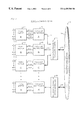
- FIG. 6 is a block diagram providing details of network translation logic within a T1(E1)-to-IP multiplexer.
- FIG. 7 is a diagram illustrating the composition of a T1 trunk packet according to the present invention for transmission over a high speed Ethernet network.
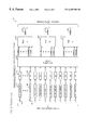
- FIG. 8 is a diagram depicting the structure of an application header for a T1 frame packet according to the present invention.
- FIG. 9 is a flow chart illustrating a method according to the present invention for transmitting T1 trunk data over a high speed data network.
- FIGS. 1 through 3 illustrate the problems associated with increasing the number of telecommunications trunks between telecommunications switches. More specifically, present day telephone service providers maintain T1/E1 equipment to provide for the transmission of telecommunications signals between T1/E1 switches, and they are beginning to provide packet-switched network equipment for the transmission of data signals between computer devices connected to a high bandwidth packet-switched network.
- the present invention solves the above-noted problems in that it provides an apparatus and method that allows telephone service providers to add T1/E1 telecommunications trunks between switches without having to utilize a T1/E1 technology network. Instead, a packet switched network is used to carry the T1/E1 signals between switches. The T1/E1 signals are translated into network data packets and these network packets are then transmitted over the service provider's existing high speed packet-switched data network.
- FIG. 1 a diagram 100 is presented illustrating how present day voices switches employ T1/E1 trunks for the transmission of telecommunications signals and how in conjunction they employ high speed data networks for the transmission of data.
- the diagram 100 depicts three central office switches 101 at locations A, B, and C.
- Telephones 102 and modems 104 are connected to central office switches 101 A and B.
- Telephones 102 are connected to central office switch B 101 .
- the central office switches 101 are interconnected by T1 trunks 110 , or higher speed trunks 110 based upon the T1 protocol.
- the diagram 100 also shows that two of the three central office switches 101 are each connected to a router 115 .
- Each of the routers 115 is connected to a high speed data network 120 .
- the diagram 100 shows two other data network devices 121 connected to the high speed data network 120 .
- These two data network devices 121 could be embodied as routers 121 for network traffic or they 121 could be data servers 121 with embedded routing equipment which are directly accessed over the network 120 .
- telephones 102 , modems 104 , and other telecommunications devices such as facsimile machines typically transmit and receive analog voice signals when communicating with a corresponding central office switch 101 .
- these central office switches 101 are geographically located within a few miles of the telephonic devices 102 , 104 because analog signals degrade over even short distances.
- the central office switch 101 is the primary point at which analog telecommunications devices 102 , 104 interface to the public switched telephone network (PSTN).
- PSTN public switched telephone network
- FIG. 1 only depicts two telephones 102 connected to each of the PSTN switches 101 , one skilled in the art will appreciate that PSTN switches 101 have the capacity to interface to thousands of telecommunications devices 102 , 104 .
- a full-duplex connection is a connection in which telecommunications signals can be simultaneously transmitted and received between the two telephones 102 .
- T-carrier T1 trunks 110 shown in FIG. 1 provide for time-division multiplexing of digitized telecommunications signals between central office switches 101 at a rate of 1.544 Mbps.
- a single T1 trunk 110 can simultaneously transmit 24 separate telephone connections (i.e., voice calls, fax transmissions, modem signals, etc.)
- T1 trunks 110 enable telephone companies (telcos) to multiplex telecommunications signals over two pairs of wires: one pair for sending and one pair for receiving, thus providing full-duplex capability.
- T1 trunks 110 have been the standard means for interconnecting PSTN switches 101 for over 30 years. As a result, the telcos have invested substantially in T1 switching equipment 101 and other equipment such as add drop multiplexers (ADMs) (not shown) in order to support the ever increasing demand for telecommunications services.
- FIG. 1 shows only one trunk 110 between switch A 101 and switch B 101 , thus providing the capability to support 24 simultaneous connections. Two trunks 110 interconnect switches A 101 and C 101 , thus supporting 48 simultaneous connections. For clarity of description, only a small number of trunks 110 are shown interconnecting the switches 101 in FIG. 1, however, one skilled in the art will appreciate that hundreds of T1 trunks 110 are typically found within present day PSTN switches 101 .
- high speed trunks using T3 or OC-48 protocol are typically provided between switches 101 .
- These high speed trunks consist of numerous aggregated T1 trunks 110 , or T1 links 110 , which are generated by ADMs.
- T1 carrier system uses a protocol similar to T1, but multiplexes 32 channels at a rate of 2.048 Mbps.
- the T1/E1-carrier system has provided an efficient and cost-effective means for interconnecting central office switches 101 , primarily because the data throughput requirements for voice transmission are much lower than that provided by the 24 channels within a T1 trunk 110 .
- Computers 103 , 121 are inherently digital devices that operate exclusively on digital data. However, for the computer 103 at point A to communicate with the computer 103 at point C, the digital data signals must first be converted into analog signals so that they are compatible the central office switches 101 .
- the modems 104 convert the data signals to analog telecommunication signals upon transmission and perform the opposite conversion upon reception. Today, dial-up modems 104 dominate the marketplace as the primary means for connecting a single computer 103 to a network of other computers 121 .
- IP Internet Protocol
- Packet-switched networks 120 utilize a layered protocol architecture that allows two devices to communicate at a higher level using one communications protocol without either of the devices having any specific knowledge of the communications protocol that is used at lower levels.
- these physical protocols include Ethernet, asynchronous transfer mode (ATM), HDLC, ISDN, and X.25.
- ATM asynchronous transfer mode
- HDLC high-speed liquid crystal display
- ISDN ISDN-to-media access control
- X.25 X.25
- a given computer 103 , 121 utilizing IP at a higher level can communicate with another computer using IP, regardless of whether the physical layer protocol is Ethernet or another physical protocol. This is advantageous to service providers because the layered architecture allows them to upgrade their physical transmission medium without affecting higher level communications.
- IP packet-switched networks 120 are now the predominant means used to interconnect large numbers of computers 103 , 121 .
- FIG. 1 shows two of the three central office switches 101 having connection points, or gateways 115 , to the packet-switched data network 120 .
- Telecommunications signals are still routed between switches 101 using traditional T1-based trunks 110 , but data signals between computers 103 are now beginning to be routed directly to the data network 120 for transmission.
- telecommunications companies are being forced increase their capacity to transmit both telecommunications signals and data.
- FIG. 2 a block diagram is presented illustrating elements within a present day central office switch 200 that are employed to convert analog telecommunications signals to digital T1 carrier signals, or T1 frames.
- the block diagram shows N incoming analog telecommunication lines 201 .
- Each of the lines 201 are connected to an 8 kHz sampler 202 .
- the output of each sampler 202 is provided to an analog-to-digital converter (A/D) 203 . All of the A/D's 203 are connected to switching logic 204 .
- the switching logic 204 provides its outputs to a number of time-division multiplexers (TDMs) 205 , each multiplexer 205 generating a T1 carrier signal for a corresponding T1 trunk 206 .
- TDMs time-division multiplexers
- a 125-microsecond segment of a T1 carrier signal that contains all 24 channels is called a T1 frame.
- the digital data for each of the 24 channels is provided from the switching logic 204 to each TDM 205 .
- 32 channels would be provided to each TDM 205 .
- the discussion focuses on the generation of T1 frames, however, one skilled in the art will appreciate that the elements of FIG. 2 can equally apply to the generation of E1 frames, the difference lying in the number of channels provided to each TDM 205 (32 versus 24), signaling bit differences, and the speed at which the TDMs 205 operate (2.048 Mbps versus 1.544 Mbps) For clarity of presentation, only three T1 trunks 206 are depicted in FIG. 2 .
- each incoming analog line 201 is sampled at 125-microsecond intervals by the 8 kHz samplers 202 . These samples, either of a voice signal, a facsimile signal, or even a modem signal, are converted by the A/Ds 203 into 8-bit digital data entities, or bytes.
- the switching logic 204 decodes the destination telephone number provided over the line 201 to determine which TDM 205 (and corresponding trunk 206 ) is to be used for transmission of a particular 8 kHz stream, or channel.
- Channel assignment for the particular 8 kHz stream within a TDM 205 is merely a function of channel, or slot, availability within the TDM 205 .
- the TDMs 205 continuously generate their corresponding T1 frames at an 8 kHz frame rate and the T1 frames are routed over corresponding trunks 206 to a destination switch.
- the T1 carrier signals are demultiplexed and each 8 kHz stream within a carrier signal is converted back into an analog signal and routed to its destination telecommunications device.
- FIG. 2 represents what occurs within a telecommunications switch 200 at a high level.
- a present day telecommunications switch not all of the incoming lines 201 are analog.
- Service providers today provide the ability to switch digital incoming signals such as ISDN and DSL, as well as analog signals.
- the outputs of the A/D's 203 are true 8-bit voice samples
- the outputs of the A/D's 203 in the case of T1 are encoded as well.
- signaling bits are also added to a bit stream.
- a present day telecommunications switch 200 does not provide single T1 signals for inter-switch links 206 . Rather, numerous T1 signals are aggregated ADM's (not shown) to output trunk signals 206 such as T3 and OC-48.
- the purpose of FIG. 2 is to portray the continuous nature of present day central office switches 200 . To preserve quality of service, incoming signals 201 must be continuously sampled, encoded, and transmitted. The function of the switching logic 204 is merely to continuously route digitized and encoded data to a proper “time slot” within a T1 frame.
- the transmission of digitized voice within a T1 frame must occur at a frequency at which a user on the receiving end cannot distinguish delivery means.
- T1 (and E1) 8 kHz frame transmission rate allows for excellent quality in the presence of nominal error conditions, i.e., conditions in which some time slots within a particular T1 (or E1) frame are missed.
- Transmission timing to the extent that samples must be continuously transmitted during a conversation, is essential to the quality of service that is provided.
- the timing attributes needed to provide good quality voice service are inherent features of a T1 (or E1) signal: it is a continuous signal. But transmissions on a packet-switched network are not continuous. The distinctions between a continuous E1 signal and a packet-switched transmission are more specifically described with reference to FIG. 3 .
- a timing diagram 300 depicting the composition of an E1 carrier signal 310 when transmitted over an E1 trunk as contrasted with commensurate data when transmitted over a 100 Mbps packet-switched network 320 .
- the timing diagram 300 shows a 1-second sequence of E1 frames 311 within the E1 carrier signal 310 .
- Each of the E1 frames 311 consist of 32 time-division multiplexed channels 312 of digitized telecommunications information.
- the timing diagram 300 also depicts a first data packet 321 and a second data packet 325 , both of which are transmitted over a 100 Mbps packet-switched network 320 .
- the two packets 321 , 325 are shown in the diagram 300 to illustrate that packet-switched transmissions over a data network 320 are not continuous transmissions. Rather, the transmissions are packetized, i.e., information is transmitted in bursts as transmissions are required rather than continuously as is the case with E1 networks 310 . In addition, the length of packet transmissions 321 , 325 need not be the equal.
- a packet-switched network 320 is often referred to as a data network 320 or an IP network 320 .
- Networks 320 operating at speeds of at least 100 Mbps are referred to as high bandwidth networks 320 , broadband networks 320 , or high speed networks 320 .
- the E1 carrier signal 310 is a continuous transmission of 125-microsecond E1 frames 311 each consisting of 32 channels 312 .
- Each of the 32 channels 312 contains an 8-bit data sample of a digitized telecommunications signal, thus resulting in a total of 256 bits of channel information per frame 311 .
- the 2.048 Mbps carrier frequency is achieved by transmitting all 32 channels 312 within a 125-microsecond interval.
- packet switched communications 321 , 325 are not continuous; they are typically transmitted as required.
- Typical data packets 321 , 325 , or datagrams 321 , 325 consist of a header field 322 , 326 and a data field 323 , 327 .
- the first device When a first device connected to the network 320 desires to communicate with a second device that is connected to the network 320 , the first device typically provides it's data to a transmission port.
- This port may be embodied either physically or virtually (i.e., provided as a semaphore within a software algorithm).
- a transmission port appends an IP header to the data that identifies a corresponding destination port on the second device through which data communications will occur.
- IP layer apparatus appends the IP header the data to form an IP packet 323 , 327 or IP datagram 323 , 327 . It is the IP packet 323 , 327 that comprises the data field 323 , 327 shown in FIG. 3 .
- the IP header provides information to a corresponding layer in the second device that will ensure transmission and delivery of the data.
- the data field 323 within packet 321 has been configured to represent the number of bytes (i.e., 106 bytes) required to transmit data commensurate with 2 sequential E1 frames 311 : 64 application data bytes representing two sequential sets of the 32 channels 312 , along with 42 bytes of IP header data and other control information.
- the data field 323 shown in packet 321 represents that data required to transmit two frames of 32-channel E1 information within a single network data packet 321 .
- physical network layer processes append physical network headers 322 , 326 to the IP packets 323 , 327 .
- the physical network headers 322 , 326 provide control information for physical layer hardware to include a destination address of a physical device on the network 320 to which the network packets 321 , 325 will be delivered, a source address of the transmitting device on the network 320 , and a packet length identifying the size of the packet 321 , 325 .
- the network medium can be any physical medium that can interface to the IP level to include wire, coaxial cable, fiber-optic cable, microwave, or satellite links.
- T1/E1 carrier system is maintained as a standard for switching equipment within the telecommunications industry because service providers have already invested substantially in T1/E1 switching equipment. A radical changeover from T1/E1 central office switches to packet-switched central office switches would not make good financial sense. Yet today there is no cost-effective way to incrementally affect this change without forfeiting a significant investment in T1/E1 equipment.
- the present invention overcomes the problems cited above by providing a cost-effective apparatus and method for incrementally upgrading the capabilities of present day T1/E1 central office switches.
- the present invention allows telephone service providers to reap benefits of packet-switched technologies without the attendant cost of completely converting over to packet-switched equipment.
- virtual T1/E1 trunks can be added between T1/E1-technology central office switches over a high bandwidth packet-switched network; T1/E1 carrier networks are no longer required.
- the present invention is more specifically described with reference to FIGS. 4 through 9.
- FIG. 4 a block diagram is presented of a system 400 according to the present invention for providing T1/E1 trunk interconnections over a high bandwidth packet-switched data network.
- the system 400 includes a plurality of existing T1 (or E1) telecommunications signal switches 410 , like those 101 , 200 described with reference to FIGS. 1 and 2.
- Each switch 410 accepts a plurality of incoming telecommunications signal sources 401 , like those 201 described with respect to FIG. 2 .
- each switch 410 is directly paired with a T1(or E1)-to-IP multiplexer 420 .
- T1 (or E1) trunk signals are provided to each multiplexer 420 via T1 (or E1) links 411 .
- Each T1 (or E1) link 411 shown in the system 400 represents what would otherwise be a requirement for a T1 or E1 trunk between the switches 410 .
- T1 (or E1) link A to B 411 represents T1 (or E1) frames output from switch A 410 and destined for switch B 410 .
- T1 (or E1) link A to N 411 represents T1 (or E1) frames output from switch A 410 and destined for switch N 410 .
- IP network packets carrying T1 (or E1) frame information are output from each of the T1(E1)-to-IP multiplexers 420 on buses 421 in a format compatible with a high speed packet-switched data network 440 .
- full-duplex 100 Base TX Ethernet switches 430 provide switching of the T1 (or E1) network packets over the high bandwidth data network 440 .
- the switches 430 access the high bandwidth network 440 via buses 431 .
- full-duplex IP routers provide routing of the IP packets over the high bandwidth network 440 .
- an Ethernet switch 430 transmits the packets more efficiently than a router because the switch 430 does not access to the IP header information within the packets.
- the high bandwidth data network 440 should operate at a speed of at least 100 Mbps.
- traffic over the network i.e., the number of frames transmitted within a single packet, should not be greater than that which the network 440 can deliver in a timely fashion.
- a typical 100 Mbps network 440 can support timely transmission frame data corresponding to 20 T1 (or E1) trunks.
- a multiplexer 420 may accept a plurality of T1 (or E1) frame sources 411 from an existing T1 (or E1) central office switch 410 .
- a multiplexer 420 provides four T1 (or E1) ports to accept four different T1 (or E1) frame sources 411 .
- the multiplexer 420 provides a variable number of T1 (or E1) ports up to a maximum of 20 ports.
- the multiplexer 420 receives the T1 (or E1) frame streams from each T1 (or E1) frame source 411 in real time and converts these streams to packets for transmission over the IP network 440 by completely encapsulating each T1 frame within a network packet using IP protocol.
- Ethernet is used for the physical layer protocol, however, one skilled in the art will appreciate that any of the high-bandwidth network protocols can be used for routing of network packets to include FDDI, X.25, and ATM.
- Packets corresponding to a particular T1 (or E1) frame stream 411 are queued over a 250-microsecond interval and then transmitted to a destination multiplexer 420 over the packet-switched network 440 .
- the destination multiplexer 420 strips away all network-related information and converts the T1 (E1) network packets back into signals compatible with a destination T1 (or E1) switch 410 .
- the destination T1 (or E1) switch 410 receives the converted T1 (or E1) stream and routes each channel in the stream to its destination signal line 401 , completely oblivious to the medium of transmission that has been used to route the stream.
- the multiplexers 420 allow true connectivity of the switches 410 over the high-bandwidth network 440 .
- most providers today are beginning to provide gateways 430 , 431 to the network 440 .
- FIG. 5 a block diagram is presented illustrating details of a T1(E1)-to-IP multiplexer 500 according to the present invention.
- the T1(E1)-to-IP multiplexer 500 includes four T1(E1) trunk interface logic ports 510 .
- up to 20 T1(E1) ports 510 are provided.
- Each T1(E1) port 510 provides full-duplex connectivity with a corresponding synchronous T1 frame stream 501 associated with a T1(E1) switch (not shown). Each port 510 transmits and receives T1(E1) data to network translation logic 520 via buses 511 .
- the network translation logic 520 comprises a PowerPCO processor card with 32 MB of random access memory (RAM).
- the network translation logic 520 provides formatted network packets to network interface logic 530 via bus 521 .
- the network interface logic 530 transmits/receives packets from a router (not shown) connected to a packet-switched network (not shown) via a gateway 531 .
- An E1-to-IP multiplexer 500 is described in Appendix A, which is attached hereto.
- T1/E1 frames are received from the T1/E1 sources 501 and are queued for a 250-microsecond interval within the network translation logic 520 . Since a T1/E1 carrier signal is a continuous and synchronous signal, the multiplexer 500 according to the present invention derives its transmit clock from the T1 signal 501 provided to each port. Thus, packet transmission corresponding to a port 510 over the network is synchronized with the data being received from that port 510 .
- the multiplexer 500 provides the capability to transmit packets for multiple ports associated with the same destination switch in a single network transmission up to a maximum of 1500 bytes per packet.
- FIG. 6 a block diagram is presented providing details of network translation logic 600 within one embodiment of a T1(E1)-to-IP multiplexer according to the present invention.
- the network translation logic includes four sets of transmit queue logic 601 and receive queue logic 602 , each of the sets 601 , 602 corresponding to a specific frame stream.
- the stream is formatted in accordance with T1 carrier protocol.
- the stream is formatted in accordance with E1 carrier protocol.
- discussion will proceed in terms of a E1 embodiment, however, one skilled in the art will appreciate that such discussion is equally applicable to a T1 carrier system.
- E1 transmit frame data is output from the transmit queue logic 601 via bus 603 to application envelope logic 610 and E1 receive frame data is provided by the application envelope logic 610 to the receive queue logic 602 via bus 604 .
- the application envelope logic 610 also includes point-to-point connection logic 612 for maintaining port address mappings to destination multiplexers.
- the application envelope logic 610 interfaces to UDP/IP/MAC prefix logic 620 via bus 611 . Formatted network packets are provided to/from a 100 Base TX port controller 630 via bus 621 .
- the port controller 630 interfaces to a network router (not shown) via gateway bus 631 .
- transmission clocks are derived from each E1 transmit stream input into a transmit queue 601 .
- E1 channel transmit data is queued for a period of 250 microseconds (i.e., two complete frames) and then dumped to the application envelope logic 610 .
- the point-to-point connection logic 612 provides trunk routing information corresponding to each E1 transmit stream.
- the trunk routing information is included in an application header that is appended to the two frames of E1 data (i.e., 64 bytes), thus forming an application packet.
- Multiple application packets that are destined for the same destination switch are grouped together by the application envelope logic 510 into the data portion of a UDP datagram and are thus provided to the UDP/IP/MAC prefix logic 620 over bus 611 .
- the UDP/IP/MAC logic 620 appends a UDP header, IP header, MAC header, and Ethernet preamble to the grouped application packets to form an Ethernet packet.
- the UDP header is appended to allow debugging to occur under a Unix environment; UDP formatting is not otherwise required. Formatted Ethernet packets are passed to the port controller 630 via bus 621 for transmission over the high bandwidth Ethernet network.
- the port controller 630 routes the packet traffic to the network via bus 631 in accordance with Ethernet protocol.
- Packets are received from the network via bus 631 and are provided by the port controller 630 to the prefix logic 620 .
- the prefix logic 620 strips away preamble and MAC, IP, and UDP header information from the received packets and provides a group of received application packets to the envelope logic 610 via bus 611 .
- the point-to-point connection logic 612 maps application header routing information within received E1 application packets to a corresponding receive queue 602 and the application envelope logic 610 in turn strips away the application headers from the application packets to reveal the data associated with two 32-channel E1 frames destined for a specific port. The data is then passed to the proper receive queue 602 via bus 604 .
- the receive queue logic 604 is continuously generating an outgoing E1 frame stream and thus inserts the queued data into the outgoing stream. During those times when latency on the packet-switched network results in an empty receive queue 602 , a condition known as a frame slip, the receive queue logic 602 generates a fill frame in accordance with T1 protocol.
- the present invention achieves latencies less than three milliseconds, end-to-end.
- the application envelope logic 610 monitors transmission and reception activity of packets at the application level.
- the envelope logic 610 also generates error messages and establishes and terminates connections between switches.
- FIG. 7 a diagram is presented illustrating the composition of an E1 trunk packet 700 according to the present invention for transmission over a high speed Ethernet network.
- the E1 trunk packet 700 consists of a number of application packets 740 , all of which are destined for the same destination multiplexer according to the present invention.
- each application packet 740 has a data field 741 and an application header 742 .
- the data field 741 in an E1 embodiment, contains 64 bytes (i.e., two consecutive frames) of digitized telecommunications data, each byte corresponding to a channel within an E1 frame.
- the data field 741 contains 48 bytes of telecommunications data (i.e., two consecutive T1 frames), each byte corresponding to a channel within a frame.
- the size of each application header 742 is 14 bytes.
- Envelope logic groups application packets 740 together into the data portion 745 of a UDP datagram.
- Prefix logic in turn appends an 8-byte UDP header 730 , a 20-byte IP header 720 , a 14-byte MAC header 710 , and a 12-byte Ethernet preamble 705 to the grouped application packets 745 .
- a network packet 700 is formatted for transmission over a high speed packet-switched network to a destination switch having a multiplexer according to the present invention.
- the application header 800 is appended to each set of T1(E1) data corresponding to two consecutive T1(E1) frames.
- the application header 800 has a version (VER) field 801 , a command (CMND) field 802 , a flags (FLAGS) field 803 , a header length (HLEN) field 804 , a source port number (SRCP) field 805 , a destination port number (DESTP) field 806 , a sequencing/not acknowledge (SEQ/NAQ) field 807 , a frame count (FRCNT) field 808 , a source session key (SRCK) field 809 , a destination session key (DESTK) field 810 , and a 4-byte reply IP address (REPIP) field 811 .
- VER version
- CMND command
- FLAGS flags
- HLEN header length
- SRCP source port number
- DESTP destination port number
- SEQ/NAQ sequencing/not acknowledge
- FRCNT frame count
- VER 801 contains a version number for application software within a multiplexer according to the present invention to ensure interoperability of multiple fielded versions of the system.
- CMND 802 indicates to a partner multiplexer whether the corresponding frames contains data, or whether the frames should be ignored, or whether the frames indicate an error code.
- FLAGS 803 indicates whether its corresponding frames are the last frames in a grouped set of frames.
- HLEN 804 indicates the number of bytes in the application header. In one embodiment, this field 804 indicates 14 bytes.
- SRCP 805 contains the T1(E1) port number in the transmitting multiplexer.
- DESTP 806 indicates the port number which is to receive the data in the corresponding frames.
- SEQ/NAQ 807 indicates a sequence number for normally transmitted frames and is used by a receiving multiplexer to detect out-of-sequence frames.
- this field 807 contains an error code.
- error codes include 1) destination port not available, 2) destination port busy, 3) destination port down, 4) invalid version number, 5) invalid CMND field 802 in a received header 800 , 6) invalid HLEN field 804 in a received header 800 , 7) all other undefined error conditions, 8) no framing on a T1(E1) port, 9) post frame as data in a log file for system maintenance.
- FRCNT 808 indicates the number of frames in a transmitting port's frame buffer.
- SRCK 809 contains a session key from a receiving switch and DESTK 810 contains a session key from the transmitting switch.
- REPIP 811 is used by a multiplexer that has multiple IP addresses to indicate which IP address it wants to receive reply data on. This enables a multiplexer according to the present invention to balance transmit and receive processing loads.
- the system according to the present invention enables a telephone service provider to utilize a gateway to a high speed packet-switched network for the purpose of providing additional T1(E1) trunks between telecommunications switches.
- the provider is not bound to increase an existing and already substantial investment in older technology networks while the market rapidly moves toward packet-switched communication networks.
- Providers can now exhaust their investment in older T1/E1 networking equipment while at the same time taking advantage of benefits of high-bandwidth data networks.
- a flow chart 900 is presented illustrating a method according to the present invention for transmitting T1/E1 trunk data over a high speed data network.
- Flow begins at block 902 where a T1/E1-to-IP multiplexer according to the present invention begins manage T1/E1 traffic between T1/E1 telecommunications switches. Flow then proceeds to block 904 .
- an incoming IP packet queue according to the present invention is read. Recently received IP packets are retrieved from the queue. Flow then proceeds to block 906 .
- packet-switched network header information is stripped from the received packets to reveal a number of T1/E1 application packets.
- Each application packet comprises an application header according to the present invention and an application data field.
- the application data field consists of data corresponding to two consecutive T1/E1 frames. Flow then proceeds to block 908 .
- the application headers are evaluated and each of the application data fields are written to T1/E1 port output queues as directed by their corresponding application header.
- T1/E1 frame data is has been received in packet form over the effected T1/E1 trunk and has been queued for delivery over T1/E1 ports within the multiplexer. Flow then proceeds to block 910 .
- the retrieved frame data is evaluated. Frame data that is targeted for delivery to a particular T1/E1 port that is within the multiplexer is placed in the particular T1/E1 port's output queue. Flow then proceeds to block 914 .
- frame data that is targeted for delivery to T1/E1 ports within a different multiplexer according to the present invention are placed in an IP output queue that corresponds to the IP address of the different multiplexer. Flow then proceeds to block 916 .
- T1/E1 output logic reads the T1/E1 frame data from each T1/E1 port output queue and inserts the T1/E1 frame data into a continuously generated T1/E1 carrier signal on each T1/E1 port. Flow then proceeds to block 920 .
- network headers are appended to data in each IP output queue resulting in a number of IP packets. Flow then proceeds to block 922 .
- each of the IP packets are transmitted over a high bandwidth packet-switched network according to the present invention. Flow then proceeds to decision block 924 .
- the method continues to perform the steps discussed with reference to blocks 904 through 924 every 120 microseconds.
- the present invention has been discussed in particular with reference to T1 and E1 telecommunications frame signals, however other, faster telecommunications protocols exist such as T2, T3, E2, E3, E4, etc., each of which employs T1(E1) as a basis waveform.
- other telecommunication protocols have been developed for wireless or RF networks, that work at speeds from 9 Mhz up. The present invention certainly comprehends such protocols to the extent that high bandwidth data networks can supply the bit rates necessary to ensure timely transmission of frame data an to provide overall quality of service.
- the present invention has been described particularly in terms of voice signals originating from a telephone for these are the most common signals presented to a T1(E1) switch for transmission.
- the present invention comprehends any type of signal or modulation that can be transmitted over a T1 carrier for the content of the signal itself is completely transparent to the apparatus and method according to the present invention.
Abstract
Description
Claims (40)
Priority Applications (3)
| Application Number | Priority Date | Filing Date | Title |
|---|---|---|---|
| US09/468,775 US6459708B1 (en) | 1999-12-21 | 1999-12-21 | Apparatus and method for providing T1/E1 telecommunications trunks over IP networks |
| AU21067/01A AU2106701A (en) | 1999-12-21 | 2000-12-16 | Apparatus and method for providing t1/e1 telecommunications trunks over ip networks |
| PCT/US2000/034120 WO2001047198A1 (en) | 1999-12-21 | 2000-12-16 | Apparatus and method for providing t1/e1 telecommunications trunks over ip networks |
Applications Claiming Priority (1)
| Application Number | Priority Date | Filing Date | Title |
|---|---|---|---|
| US09/468,775 US6459708B1 (en) | 1999-12-21 | 1999-12-21 | Apparatus and method for providing T1/E1 telecommunications trunks over IP networks |
Publications (1)
| Publication Number | Publication Date |
|---|---|
| US6459708B1 true US6459708B1 (en) | 2002-10-01 |
Family
ID=23861189
Family Applications (1)
| Application Number | Title | Priority Date | Filing Date |
|---|---|---|---|
| US09/468,775 Expired - Lifetime US6459708B1 (en) | 1999-12-21 | 1999-12-21 | Apparatus and method for providing T1/E1 telecommunications trunks over IP networks |
Country Status (3)
| Country | Link |
|---|---|
| US (1) | US6459708B1 (en) |
| AU (1) | AU2106701A (en) |
| WO (1) | WO2001047198A1 (en) |
Cited By (32)
| Publication number | Priority date | Publication date | Assignee | Title |
|---|---|---|---|---|
| US20020044547A1 (en) * | 2000-01-11 | 2002-04-18 | Dalton James P. G. | Architectures for clearing and settlement services between internet telephony clearinghouses |
| US20020085558A1 (en) * | 2000-12-29 | 2002-07-04 | George Edward N. | Low speed modem transmission over packet networks |
| US20020105949A1 (en) * | 2001-02-06 | 2002-08-08 | Daisuke Shinomiya | Band control device |
| US20030091070A1 (en) * | 2001-08-22 | 2003-05-15 | Tekelec | Methods and systems for improving utilization of high-speed time division multiplexed communications links at signal transfer point |
| US20040001507A1 (en) * | 2002-05-14 | 2004-01-01 | Wilfried Krug | Data network interface and communication devices having a data network interface |
| US6731649B1 (en) | 2000-07-26 | 2004-05-04 | Rad Data Communication Ltd. | TDM over IP (IP circuit emulation service) |
| US20040264961A1 (en) * | 2003-06-12 | 2004-12-30 | Nam Hong Soon | Ethernet passive optical network system, and optical network terminal and optical line terminal provided in the same |
| US20050021761A1 (en) * | 2000-06-29 | 2005-01-27 | Transnexus, Inc. | Intelligent end user devices for clearinghouse services in an internet telephony system |
| US6898213B1 (en) * | 2000-10-16 | 2005-05-24 | Iprad Ltd. | Circuit emulation service (CES) over IP |
| US20050142937A1 (en) * | 2003-12-30 | 2005-06-30 | Kuotung Lin | Coaxial connector structure |
| US20050201364A1 (en) * | 2004-03-11 | 2005-09-15 | Transnexus, Inc. | Method and system for routing calls over a packet switched computer network |
| US6950441B1 (en) | 1999-03-30 | 2005-09-27 | Sonus Networks, Inc. | System and method to internetwork telecommunication networks of different protocols |
| US6963561B1 (en) * | 2000-12-15 | 2005-11-08 | Atrica Israel Ltd. | Facility for transporting TDM streams over an asynchronous ethernet network using internet protocol |
| US20060155998A1 (en) * | 2000-09-11 | 2006-07-13 | Transnexus, Inc. | Clearinghouse server for internet telephony and multimedia communications |
| US20060165068A1 (en) * | 2004-12-13 | 2006-07-27 | Dalton James P Jr | Method and system for securely authorized VoIP Interconnections between anonymous peers of VoIP networks |
| US7133417B1 (en) * | 1999-07-02 | 2006-11-07 | Cisco Technology, Inc. | Multipath voice switching method and apparatus |
| US20070053364A1 (en) * | 2005-06-17 | 2007-03-08 | Alcatel | Encapsulation of E1-type frames under Ethernet |
| US7203956B2 (en) | 1999-12-22 | 2007-04-10 | Transnexus, Inc. | System and method for the secure enrollment of devices with a clearinghouse server for internet telephony and multimedia communications |
| US20070217380A1 (en) * | 2006-03-20 | 2007-09-20 | Alcatel Lucent | Method and Apparatus for Implementing a Uniform Platform for Data/Voice Service |
| US20070248073A1 (en) * | 2002-02-01 | 2007-10-25 | Harris Corporation | Method and system for encapsulating time division multiplex data into individual packets of a packet based network |
| US20080089356A1 (en) * | 2006-10-11 | 2008-04-17 | Hon Hai Precision Industry Co., Ltd. | VoIP device and service switching method thereof |
| CN100384177C (en) * | 2004-07-14 | 2008-04-23 | 华为技术有限公司 | A method of Ethernet transmission in a plurality of E1 channels |
| US7457320B1 (en) * | 2001-09-05 | 2008-11-25 | Predrag Filipovic | Synchronization using multicasting |
| US7525956B2 (en) | 2001-01-11 | 2009-04-28 | Transnexus, Inc. | Architectures for clearing and settlement services between internet telephony clearinghouses |
| US20090304012A1 (en) * | 2006-07-04 | 2009-12-10 | Marthinus Casper Ackerman | Gateway for use in an electronic communications recording system |
| US20110090796A1 (en) * | 1999-12-30 | 2011-04-21 | Avaya Inc. | ADAPTIVELY MAINTAINING QUALITY OF SERVICE (QoS) IN DISTRIBUTED PBX NETWORKS |
| US7990882B1 (en) | 1999-12-30 | 2011-08-02 | Avaya Inc. | Adaptively maintaining quality of service (QoS) in distributed PBX networks |
| WO2012001016A1 (en) | 2010-06-28 | 2012-01-05 | Skype Ireland Technologies Holdings Limited | Dynamic call routing for real-time handling of inbound voice calls on mobile phones |
| US8238329B2 (en) | 2005-12-13 | 2012-08-07 | Transnexus, Inc. | Method and system for securely authorizing VoIP interconnections between anonymous peers of VoIP networks |
| US20130258903A1 (en) * | 2005-11-02 | 2013-10-03 | Verizon Corporate Services Group Inc. | Systems and methods for modeling telecommunication switch investments |
| US20130279509A1 (en) * | 2011-01-04 | 2013-10-24 | Napatech A/S | Apparatus and method for receiving and forwarding data |
| US8781086B2 (en) | 2012-06-26 | 2014-07-15 | Adc Dsl Systems, Inc. | System and method for circuit emulation |
Families Citing this family (1)
| Publication number | Priority date | Publication date | Assignee | Title |
|---|---|---|---|---|
| KR100449574B1 (en) | 2002-04-08 | 2004-09-22 | 주식회사 케이티프리텔 | Low-cost network system between a base station controller and a base transceiver station, and method for transmitting data between them |
Citations (13)
| Publication number | Priority date | Publication date | Assignee | Title |
|---|---|---|---|---|
| US4740955A (en) * | 1986-10-29 | 1988-04-26 | Tie/Communications, Inc. | Communications system having voice and digital data capability and employing a plurality of voice and data buses in main service unit and serial packetized transmission to and from telephones |
| US5426637A (en) * | 1992-12-14 | 1995-06-20 | International Business Machines Corporation | Methods and apparatus for interconnecting local area networks with wide area backbone networks |
| US5440616A (en) * | 1994-02-10 | 1995-08-08 | Rolm Company | Method and apparatus for interconnecting a messaging system and a private branch exchange |
| US5682386A (en) * | 1994-04-19 | 1997-10-28 | Multi-Tech Systems, Inc. | Data/voice/fax compression multiplexer |
| US5892764A (en) * | 1996-09-16 | 1999-04-06 | Sphere Communications Inc. | ATM LAN telephone system |
| WO1999026387A1 (en) | 1997-11-14 | 1999-05-27 | 3Com Corporation | Distributed processing of high level protocols, such as real time transport protocols, in a network access server |
| US5910946A (en) * | 1997-01-13 | 1999-06-08 | Samsung Electronics Co., Ltd. | Wireless internet network architecture for voice and data communications |
| US6044080A (en) * | 1996-11-19 | 2000-03-28 | Pluris, Inc. | Scalable parallel packet router |
| US6064653A (en) * | 1997-01-07 | 2000-05-16 | Bell Atlantic Network Services, Inc. | Internetwork gateway to gateway alternative communication |
| US6069890A (en) * | 1996-06-26 | 2000-05-30 | Bell Atlantic Network Services, Inc. | Internet telephone service |
| EP1026848A2 (en) | 1999-02-04 | 2000-08-09 | Net Insight AB | Method for mapping data |
| US6219348B1 (en) * | 1998-04-30 | 2001-04-17 | Sbc Technology Resources, Inc. | ATM-based distributed virtual tandem switching system |
| US6298043B1 (en) * | 1998-03-28 | 2001-10-02 | Nortel Networks Limited | Communication system architecture and a connection verification mechanism therefor |
-
1999
- 1999-12-21 US US09/468,775 patent/US6459708B1/en not_active Expired - Lifetime
-
2000
- 2000-12-16 AU AU21067/01A patent/AU2106701A/en not_active Abandoned
- 2000-12-16 WO PCT/US2000/034120 patent/WO2001047198A1/en active Application Filing
Patent Citations (13)
| Publication number | Priority date | Publication date | Assignee | Title |
|---|---|---|---|---|
| US4740955A (en) * | 1986-10-29 | 1988-04-26 | Tie/Communications, Inc. | Communications system having voice and digital data capability and employing a plurality of voice and data buses in main service unit and serial packetized transmission to and from telephones |
| US5426637A (en) * | 1992-12-14 | 1995-06-20 | International Business Machines Corporation | Methods and apparatus for interconnecting local area networks with wide area backbone networks |
| US5440616A (en) * | 1994-02-10 | 1995-08-08 | Rolm Company | Method and apparatus for interconnecting a messaging system and a private branch exchange |
| US5682386A (en) * | 1994-04-19 | 1997-10-28 | Multi-Tech Systems, Inc. | Data/voice/fax compression multiplexer |
| US6069890A (en) * | 1996-06-26 | 2000-05-30 | Bell Atlantic Network Services, Inc. | Internet telephone service |
| US5892764A (en) * | 1996-09-16 | 1999-04-06 | Sphere Communications Inc. | ATM LAN telephone system |
| US6044080A (en) * | 1996-11-19 | 2000-03-28 | Pluris, Inc. | Scalable parallel packet router |
| US6064653A (en) * | 1997-01-07 | 2000-05-16 | Bell Atlantic Network Services, Inc. | Internetwork gateway to gateway alternative communication |
| US5910946A (en) * | 1997-01-13 | 1999-06-08 | Samsung Electronics Co., Ltd. | Wireless internet network architecture for voice and data communications |
| WO1999026387A1 (en) | 1997-11-14 | 1999-05-27 | 3Com Corporation | Distributed processing of high level protocols, such as real time transport protocols, in a network access server |
| US6298043B1 (en) * | 1998-03-28 | 2001-10-02 | Nortel Networks Limited | Communication system architecture and a connection verification mechanism therefor |
| US6219348B1 (en) * | 1998-04-30 | 2001-04-17 | Sbc Technology Resources, Inc. | ATM-based distributed virtual tandem switching system |
| EP1026848A2 (en) | 1999-02-04 | 2000-08-09 | Net Insight AB | Method for mapping data |
Non-Patent Citations (4)
| Title |
|---|
| Raffaele Noro, XP-000991295, "Circuit Emulation Over IP Networks", Aug. 25, 1999, pp. 187-201. |
| Ramnath A. Lakshmi-Ratan, XP-000851517, The Lucent Technologies Softswitch-Realizing The Promise Of Convergence, Apr. 2, 1999, p. 176, col. 2, line 10-p. 181, col. 2, line 16. |
| Ramnath A. Lakshmi-Ratan, XP-000851517, The Lucent Technologies Softswitch—Realizing The Promise Of Convergence, Apr. 2, 1999, p. 176, col. 2, line 10—p. 181, col. 2, line 16. |
| Shaul Berger, XP-000992213, "Implement A Single-Chip, Multichannel VoIP DSP Engine", May 25, 2000, pp. 101-105. |
Cited By (66)
| Publication number | Priority date | Publication date | Assignee | Title |
|---|---|---|---|---|
| US6950441B1 (en) | 1999-03-30 | 2005-09-27 | Sonus Networks, Inc. | System and method to internetwork telecommunication networks of different protocols |
| US9614971B2 (en) | 1999-06-29 | 2017-04-04 | Transnexus, Inc. | Intelligent end user devices for clearinghouse services in an internet telephony system |
| US7133417B1 (en) * | 1999-07-02 | 2006-11-07 | Cisco Technology, Inc. | Multipath voice switching method and apparatus |
| US7398551B2 (en) | 1999-12-22 | 2008-07-08 | Transnexus, Inc. | System and method for the secure enrollment of devices with a clearinghouse server for internet telephony and multimedia communications |
| US7203956B2 (en) | 1999-12-22 | 2007-04-10 | Transnexus, Inc. | System and method for the secure enrollment of devices with a clearinghouse server for internet telephony and multimedia communications |
| US20110090796A1 (en) * | 1999-12-30 | 2011-04-21 | Avaya Inc. | ADAPTIVELY MAINTAINING QUALITY OF SERVICE (QoS) IN DISTRIBUTED PBX NETWORKS |
| US7990882B1 (en) | 1999-12-30 | 2011-08-02 | Avaya Inc. | Adaptively maintaining quality of service (QoS) in distributed PBX networks |
| US8477602B2 (en) | 1999-12-30 | 2013-07-02 | Avaya Inc. | Adaptively maintaining quality of service (QoS) in distributed PBX networks |
| US20020044547A1 (en) * | 2000-01-11 | 2002-04-18 | Dalton James P. G. | Architectures for clearing and settlement services between internet telephony clearinghouses |
| US6996093B2 (en) * | 2000-01-11 | 2006-02-07 | Transnexus, Inc. | Architectures for clearing and settlement services between internet telephony clearinghouses |
| US8909793B2 (en) | 2000-06-29 | 2014-12-09 | Transnexus, Inc. | Intelligent end user devices for clearinghouse services in an Internet telephony system |
| US8185636B2 (en) | 2000-06-29 | 2012-05-22 | Transnexus, Inc. | Intelligent end user devices for clearinghouse services in an internet telephony system |
| US20090147773A1 (en) * | 2000-06-29 | 2009-06-11 | Transnexus, Inc. | Intelligent end user devices for clearinghouse services in an internet telephony system |
| US7444407B2 (en) | 2000-06-29 | 2008-10-28 | Transnexus, Inc. | Intelligent end user devices for clearinghouse services in an internet telephony system |
| US20050021761A1 (en) * | 2000-06-29 | 2005-01-27 | Transnexus, Inc. | Intelligent end user devices for clearinghouse services in an internet telephony system |
| US6731649B1 (en) | 2000-07-26 | 2004-05-04 | Rad Data Communication Ltd. | TDM over IP (IP circuit emulation service) |
| US9094504B2 (en) | 2000-09-11 | 2015-07-28 | Transnexus, Inc. | Clearinghouse server for internet telephony and multimedia communications |
| US20060155998A1 (en) * | 2000-09-11 | 2006-07-13 | Transnexus, Inc. | Clearinghouse server for internet telephony and multimedia communications |
| US8289974B2 (en) | 2000-09-11 | 2012-10-16 | Transnexus, Inc. | Clearinghouse server for internet telephony and multimedia communications |
| US7912067B2 (en) | 2000-09-11 | 2011-03-22 | Transnexus, Inc. | Clearinghouse server for internet telephony and multimedia communications |
| US9979830B2 (en) | 2000-09-11 | 2018-05-22 | Transnexus, Inc. | Clearinghouse server for internet telephony and multimedia communications |
| US6898213B1 (en) * | 2000-10-16 | 2005-05-24 | Iprad Ltd. | Circuit emulation service (CES) over IP |
| US6963561B1 (en) * | 2000-12-15 | 2005-11-08 | Atrica Israel Ltd. | Facility for transporting TDM streams over an asynchronous ethernet network using internet protocol |
| US6965600B2 (en) * | 2000-12-29 | 2005-11-15 | Texas Instruments Incorporated | Low speed modem transmission over packet networks |
| US20020085558A1 (en) * | 2000-12-29 | 2002-07-04 | George Edward N. | Low speed modem transmission over packet networks |
| US20090245237A1 (en) * | 2001-01-11 | 2009-10-01 | Transnexus, Inc. | Architectures for clearing and settlement services between internet telephony clearinghouses |
| US7525956B2 (en) | 2001-01-11 | 2009-04-28 | Transnexus, Inc. | Architectures for clearing and settlement services between internet telephony clearinghouses |
| US9088628B2 (en) | 2001-01-11 | 2015-07-21 | Transnexus, Inc. | Architectures for clearing and settlement services between internet telephony clearinghouses |
| US8306020B2 (en) | 2001-01-11 | 2012-11-06 | Transnexus, Inc. | Architectures for clearing and settlement services between Internet telephony clearinghouses |
| US20020105949A1 (en) * | 2001-02-06 | 2002-08-08 | Daisuke Shinomiya | Band control device |
| US7468988B2 (en) * | 2001-08-22 | 2008-12-23 | Tekelec | Methods and systems for improving utilization of high-speed time division multiplexed communications links at signal transfer point |
| US20030091070A1 (en) * | 2001-08-22 | 2003-05-15 | Tekelec | Methods and systems for improving utilization of high-speed time division multiplexed communications links at signal transfer point |
| US8477810B2 (en) | 2001-09-05 | 2013-07-02 | Lee Capital Llc | Synchronization using multicasting |
| US20090067452A1 (en) * | 2001-09-05 | 2009-03-12 | Predrag Filipovic | Synchronization using multicasting |
| US7457320B1 (en) * | 2001-09-05 | 2008-11-25 | Predrag Filipovic | Synchronization using multicasting |
| US8189553B2 (en) | 2002-02-01 | 2012-05-29 | Harris Corporation | Method and system for encapsulating time division multiplex data into individual packets of a packet based network |
| US20070248073A1 (en) * | 2002-02-01 | 2007-10-25 | Harris Corporation | Method and system for encapsulating time division multiplex data into individual packets of a packet based network |
| US20040001507A1 (en) * | 2002-05-14 | 2004-01-01 | Wilfried Krug | Data network interface and communication devices having a data network interface |
| US7808973B2 (en) * | 2002-05-14 | 2010-10-05 | Siemens Aktiengesellschaft | Data network interface and communication devices having a data network interface |
| US20040264961A1 (en) * | 2003-06-12 | 2004-12-30 | Nam Hong Soon | Ethernet passive optical network system, and optical network terminal and optical line terminal provided in the same |
| US20050142937A1 (en) * | 2003-12-30 | 2005-06-30 | Kuotung Lin | Coaxial connector structure |
| US20100278173A1 (en) * | 2004-03-11 | 2010-11-04 | Transnexus, Inc. | Method and system for routing calls over a packet switched computer network |
| US20050201364A1 (en) * | 2004-03-11 | 2005-09-15 | Transnexus, Inc. | Method and system for routing calls over a packet switched computer network |
| US8396056B2 (en) | 2004-03-11 | 2013-03-12 | Transnexus, Inc. | Method and system for routing calls over a packet switched computer network |
| US9094418B2 (en) | 2004-03-11 | 2015-07-28 | Transnexus, Inc. | Method and system for routing calls over a packet switched computer network |
| US7743263B2 (en) | 2004-03-11 | 2010-06-22 | Transnexus, Inc. | Method and system for routing calls over a packet switched computer network |
| CN100384177C (en) * | 2004-07-14 | 2008-04-23 | 华为技术有限公司 | A method of Ethernet transmission in a plurality of E1 channels |
| US7457283B2 (en) | 2004-12-13 | 2008-11-25 | Transnexus, Inc. | Method and system for securely authorized VoIP interconnections between anonymous peers of VoIP networks |
| US20060165068A1 (en) * | 2004-12-13 | 2006-07-27 | Dalton James P Jr | Method and system for securely authorized VoIP Interconnections between anonymous peers of VoIP networks |
| US9392033B2 (en) | 2004-12-13 | 2016-07-12 | Transnexus, Inc. | Method and system for securely authorizing VoIP interconnections between anonymous peers of VoIP networks |
| US8040887B2 (en) * | 2005-06-17 | 2011-10-18 | Alcatel Lucent | Encapsulation of E1-type frames under ethernet |
| US20070053364A1 (en) * | 2005-06-17 | 2007-03-08 | Alcatel | Encapsulation of E1-type frames under Ethernet |
| US8914304B2 (en) * | 2005-11-02 | 2014-12-16 | Verizon Patent And Licensing Inc. | Systems and methods for modeling telecommunication switch investments |
| US20130258903A1 (en) * | 2005-11-02 | 2013-10-03 | Verizon Corporate Services Group Inc. | Systems and methods for modeling telecommunication switch investments |
| US8681781B2 (en) | 2005-12-13 | 2014-03-25 | Transnexus, Inc. | Method and system for securely authorizing VoIP interconnections between anonymous peers of VoIP networks |
| US8238329B2 (en) | 2005-12-13 | 2012-08-07 | Transnexus, Inc. | Method and system for securely authorizing VoIP interconnections between anonymous peers of VoIP networks |
| US10057303B2 (en) | 2005-12-13 | 2018-08-21 | Transnexus, Inc. | Method and system for securely authorizing VoIP interconnections between anonymous peers of VoIP networks |
| US7864743B2 (en) * | 2006-03-20 | 2011-01-04 | Alcatel Lucent | Method and apparatus for implementing a uniform platform for data/voice service |
| US20070217380A1 (en) * | 2006-03-20 | 2007-09-20 | Alcatel Lucent | Method and Apparatus for Implementing a Uniform Platform for Data/Voice Service |
| US20090304012A1 (en) * | 2006-07-04 | 2009-12-10 | Marthinus Casper Ackerman | Gateway for use in an electronic communications recording system |
| US8036236B2 (en) * | 2006-07-04 | 2011-10-11 | Vastech Sa (Pty) Limited | Gateway for use in an electronic communications recording system |
| US20080089356A1 (en) * | 2006-10-11 | 2008-04-17 | Hon Hai Precision Industry Co., Ltd. | VoIP device and service switching method thereof |
| WO2012001016A1 (en) | 2010-06-28 | 2012-01-05 | Skype Ireland Technologies Holdings Limited | Dynamic call routing for real-time handling of inbound voice calls on mobile phones |
| US20130279509A1 (en) * | 2011-01-04 | 2013-10-24 | Napatech A/S | Apparatus and method for receiving and forwarding data |
| US9246850B2 (en) * | 2011-01-04 | 2016-01-26 | Napatech A/S | Apparatus and method for receiving and forwarding data |
| US8781086B2 (en) | 2012-06-26 | 2014-07-15 | Adc Dsl Systems, Inc. | System and method for circuit emulation |
Also Published As
| Publication number | Publication date |
|---|---|
| AU2106701A (en) | 2001-07-03 |
| WO2001047198A1 (en) | 2001-06-28 |
Similar Documents
| Publication | Publication Date | Title |
|---|---|---|
| US6459708B1 (en) | Apparatus and method for providing T1/E1 telecommunications trunks over IP networks | |
| CA2339116C (en) | Apparatus and method for a telephony gateway | |
| US6128293A (en) | Multiservice access management system | |
| US7006489B2 (en) | Voice packet switching system and method | |
| US6075784A (en) | System and method for communicating voice and data over a local packet network | |
| EP1176774B1 (en) | TDM over IP (IP circuit emulation service) | |
| US6009100A (en) | Asynchronous transfer mode switching system | |
| US5623491A (en) | Device for adapting narrowband voice traffic of a local access network to allow transmission over a broadband asynchronous transfer mode network | |
| CA2334927C (en) | Digital packet network for the local access loop | |
| US7012922B1 (en) | Packet communications system and method | |
| JP3805096B2 (en) | Voice / data integrated communication device | |
| WO1996019059A2 (en) | Packet based data transmission system | |
| US7633936B1 (en) | Time-slot interchange circuit | |
| JPH08237305A (en) | Method of transmitting voice signal in packet exchange network | |
| US6912217B1 (en) | Protocol stack encapsulation for voice processor | |
| WO1999065269A1 (en) | System for transmitting data between circuit boards in a housing | |
| US6490294B1 (en) | Apparatus and method for interconnecting isochronous systems over packet-switched networks | |
| Cisco | Overview | |
| KR100276626B1 (en) | Signal Processing Method for Performance Improvement of Interworking Function in Asynchronous Transmission Mode Public Network | |
| EP1014670A2 (en) | Telecommunication system with a multi-channel digital subsciber line interface and method | |
| US7324557B2 (en) | Method, switching devices and remote connection unit for transmitting data having a reduced bandwidth | |
| KR20000017063A (en) | Edge vehicle for a communications network | |
| JP2002044155A (en) | Individual line termination method and system in virtual switching function on ip network | |
| CA2270806A1 (en) | Digital data protocol converter |
Legal Events
| Date | Code | Title | Description |
|---|---|---|---|
| AS | Assignment |
Owner name: TOLEDO COMMUNICATIONS INC., TEXAS Free format text: ASSIGNMENT OF ASSIGNORS INTEREST;ASSIGNORS:COX, JAMES;GERLACH, JACK;MOTT, JAMES;AND OTHERS;REEL/FRAME:010505/0584 Effective date: 19991217 |
|
| STCF | Information on status: patent grant |
Free format text: PATENTED CASE |
|
| FPAY | Fee payment |
Year of fee payment: 4 |
|
| AS | Assignment |
Owner name: HUFFMAN, JAMES W, COLORADO Free format text: ASSIGNMENT OF ASSIGNORS INTEREST;ASSIGNOR:TOLEDO COMMUNICATIONS INC.;REEL/FRAME:018224/0782 Effective date: 20060911 |
|
| AS | Assignment |
Owner name: BELTRANE LIMITED LLC, DELAWARE Free format text: ASSIGNMENT OF ASSIGNORS INTEREST;ASSIGNOR:HUFFMAN, JAMES W.;REEL/FRAME:019767/0056 Effective date: 20061010 |
|
| FEPP | Fee payment procedure |
Free format text: PAT HOLDER NO LONGER CLAIMS SMALL ENTITY STATUS, ENTITY STATUS SET TO UNDISCOUNTED (ORIGINAL EVENT CODE: STOL); ENTITY STATUS OF PATENT OWNER: LARGE ENTITY |
|
| FEPP | Fee payment procedure |
Free format text: PAYOR NUMBER ASSIGNED (ORIGINAL EVENT CODE: ASPN); ENTITY STATUS OF PATENT OWNER: LARGE ENTITY Free format text: PAYER NUMBER DE-ASSIGNED (ORIGINAL EVENT CODE: RMPN); ENTITY STATUS OF PATENT OWNER: LARGE ENTITY |
|
| FPAY | Fee payment |
Year of fee payment: 8 |
|
| FPAY | Fee payment |
Year of fee payment: 12 |
|
| AS | Assignment |
Owner name: BENHOV GMBH, LLC, DELAWARE Free format text: MERGER;ASSIGNOR:BELTRANE LIMITED LLC;REEL/FRAME:036928/0568 Effective date: 20150811 |
|
| AS | Assignment |
Owner name: INTELLECTUAL VENTURES ASSETS 79 LLC, DELAWARE Free format text: ASSIGNMENT OF ASSIGNORS INTEREST;ASSIGNOR:BENHOV GMBH, LLC;REEL/FRAME:045718/0188 Effective date: 20180419 |
|
| AS | Assignment |
Owner name: NORDIC INTERACTIVE TECHNOLOGIES LLC, TEXAS Free format text: ASSIGNMENT OF ASSIGNORS INTEREST;ASSIGNOR:INTELLECTUAL VENTURES ASSETS 79 LLC;REEL/FRAME:045757/0426 Effective date: 20180501 |