US6459989B1 - Portable integrated indoor and outdoor positioning system and method - Google Patents
Portable integrated indoor and outdoor positioning system and method Download PDFInfo
- Publication number
- US6459989B1 US6459989B1 US09/517,897 US51789700A US6459989B1 US 6459989 B1 US6459989 B1 US 6459989B1 US 51789700 A US51789700 A US 51789700A US 6459989 B1 US6459989 B1 US 6459989B1
- Authority
- US
- United States
- Prior art keywords
- communication unit
- signal
- communication
- position information
- time
- Prior art date
- Legal status (The legal status is an assumption and is not a legal conclusion. Google has not performed a legal analysis and makes no representation as to the accuracy of the status listed.)
- Expired - Fee Related
Links
Images


Classifications
-
- G—PHYSICS
- G01—MEASURING; TESTING
- G01S—RADIO DIRECTION-FINDING; RADIO NAVIGATION; DETERMINING DISTANCE OR VELOCITY BY USE OF RADIO WAVES; LOCATING OR PRESENCE-DETECTING BY USE OF THE REFLECTION OR RERADIATION OF RADIO WAVES; ANALOGOUS ARRANGEMENTS USING OTHER WAVES
- G01S5/00—Position-fixing by co-ordinating two or more direction or position line determinations; Position-fixing by co-ordinating two or more distance determinations
- G01S5/0009—Transmission of position information to remote stations
- G01S5/0018—Transmission from mobile station to base station
- G01S5/0027—Transmission from mobile station to base station of actual mobile position, i.e. position determined on mobile
-
- G—PHYSICS
- G01—MEASURING; TESTING
- G01S—RADIO DIRECTION-FINDING; RADIO NAVIGATION; DETERMINING DISTANCE OR VELOCITY BY USE OF RADIO WAVES; LOCATING OR PRESENCE-DETECTING BY USE OF THE REFLECTION OR RERADIATION OF RADIO WAVES; ANALOGOUS ARRANGEMENTS USING OTHER WAVES
- G01S19/00—Satellite radio beacon positioning systems; Determining position, velocity or attitude using signals transmitted by such systems
- G01S19/01—Satellite radio beacon positioning systems transmitting time-stamped messages, e.g. GPS [Global Positioning System], GLONASS [Global Orbiting Navigation Satellite System] or GALILEO
- G01S19/03—Cooperating elements; Interaction or communication between different cooperating elements or between cooperating elements and receivers
- G01S19/10—Cooperating elements; Interaction or communication between different cooperating elements or between cooperating elements and receivers providing dedicated supplementary positioning signals
-
- G—PHYSICS
- G01—MEASURING; TESTING
- G01S—RADIO DIRECTION-FINDING; RADIO NAVIGATION; DETERMINING DISTANCE OR VELOCITY BY USE OF RADIO WAVES; LOCATING OR PRESENCE-DETECTING BY USE OF THE REFLECTION OR RERADIATION OF RADIO WAVES; ANALOGOUS ARRANGEMENTS USING OTHER WAVES
- G01S19/00—Satellite radio beacon positioning systems; Determining position, velocity or attitude using signals transmitted by such systems
- G01S19/01—Satellite radio beacon positioning systems transmitting time-stamped messages, e.g. GPS [Global Positioning System], GLONASS [Global Orbiting Navigation Satellite System] or GALILEO
- G01S19/13—Receivers
- G01S19/14—Receivers specially adapted for specific applications
-
- G—PHYSICS
- G01—MEASURING; TESTING
- G01S—RADIO DIRECTION-FINDING; RADIO NAVIGATION; DETERMINING DISTANCE OR VELOCITY BY USE OF RADIO WAVES; LOCATING OR PRESENCE-DETECTING BY USE OF THE REFLECTION OR RERADIATION OF RADIO WAVES; ANALOGOUS ARRANGEMENTS USING OTHER WAVES
- G01S19/00—Satellite radio beacon positioning systems; Determining position, velocity or attitude using signals transmitted by such systems
- G01S19/38—Determining a navigation solution using signals transmitted by a satellite radio beacon positioning system
- G01S19/39—Determining a navigation solution using signals transmitted by a satellite radio beacon positioning system the satellite radio beacon positioning system transmitting time-stamped messages, e.g. GPS [Global Positioning System], GLONASS [Global Orbiting Navigation Satellite System] or GALILEO
- G01S19/42—Determining position
- G01S19/48—Determining position by combining or switching between position solutions derived from the satellite radio beacon positioning system and position solutions derived from a further system
-
- G—PHYSICS
- G01—MEASURING; TESTING
- G01S—RADIO DIRECTION-FINDING; RADIO NAVIGATION; DETERMINING DISTANCE OR VELOCITY BY USE OF RADIO WAVES; LOCATING OR PRESENCE-DETECTING BY USE OF THE REFLECTION OR RERADIATION OF RADIO WAVES; ANALOGOUS ARRANGEMENTS USING OTHER WAVES
- G01S1/00—Beacons or beacon systems transmitting signals having a characteristic or characteristics capable of being detected by non-directional receivers and defining directions, positions, or position lines fixed relatively to the beacon transmitters; Receivers co-operating therewith
- G01S1/72—Beacons or beacon systems transmitting signals having a characteristic or characteristics capable of being detected by non-directional receivers and defining directions, positions, or position lines fixed relatively to the beacon transmitters; Receivers co-operating therewith using ultrasonic, sonic or infrasonic waves
- G01S1/725—Marker, boundary, call-sign or like beacons transmitting signals not carrying directional information
-
- G—PHYSICS
- G01—MEASURING; TESTING
- G01S—RADIO DIRECTION-FINDING; RADIO NAVIGATION; DETERMINING DISTANCE OR VELOCITY BY USE OF RADIO WAVES; LOCATING OR PRESENCE-DETECTING BY USE OF THE REFLECTION OR RERADIATION OF RADIO WAVES; ANALOGOUS ARRANGEMENTS USING OTHER WAVES
- G01S15/00—Systems using the reflection or reradiation of acoustic waves, e.g. sonar systems
- G01S15/74—Systems using reradiation of acoustic waves, e.g. IFF, i.e. identification of friend or foe
-
- G—PHYSICS
- G01—MEASURING; TESTING
- G01S—RADIO DIRECTION-FINDING; RADIO NAVIGATION; DETERMINING DISTANCE OR VELOCITY BY USE OF RADIO WAVES; LOCATING OR PRESENCE-DETECTING BY USE OF THE REFLECTION OR RERADIATION OF RADIO WAVES; ANALOGOUS ARRANGEMENTS USING OTHER WAVES
- G01S19/00—Satellite radio beacon positioning systems; Determining position, velocity or attitude using signals transmitted by such systems
- G01S19/38—Determining a navigation solution using signals transmitted by a satellite radio beacon positioning system
- G01S19/39—Determining a navigation solution using signals transmitted by a satellite radio beacon positioning system the satellite radio beacon positioning system transmitting time-stamped messages, e.g. GPS [Global Positioning System], GLONASS [Global Orbiting Navigation Satellite System] or GALILEO
- G01S19/42—Determining position
- G01S19/45—Determining position by combining measurements of signals from the satellite radio beacon positioning system with a supplementary measurement
- G01S19/46—Determining position by combining measurements of signals from the satellite radio beacon positioning system with a supplementary measurement the supplementary measurement being of a radio-wave signal type
-
- G—PHYSICS
- G01—MEASURING; TESTING
- G01S—RADIO DIRECTION-FINDING; RADIO NAVIGATION; DETERMINING DISTANCE OR VELOCITY BY USE OF RADIO WAVES; LOCATING OR PRESENCE-DETECTING BY USE OF THE REFLECTION OR RERADIATION OF RADIO WAVES; ANALOGOUS ARRANGEMENTS USING OTHER WAVES
- G01S2205/00—Position-fixing by co-ordinating two or more direction or position line determinations; Position-fixing by co-ordinating two or more distance determinations
- G01S2205/001—Transmission of position information to remote stations
- G01S2205/002—Transmission of position information to remote stations for traffic control, mobile tracking, guidance, surveillance or anti-collision
Definitions
- the invention relates generally to positioning systems. More specifically, the invention relates to positioning systems that integrate global positioning systems with indoor positioning systems.
- GPS Global positioning systems
- L 1 L-band carrier
- the L 1 carrier component is modulated by a course acquisition (C/A) pseudo random noise (PRN) code component and a data component.
- the PRN code component provides timing information for determining when a satellite transmitted the GPS signal.
- the data component includes information such as the orbital position of the transmitting satellite. From the timing and satellite orbital position information in the PRN code and data components obtained from the GPS signals of at least four GPS satellites, the GPS receiver performs ranging measurements. By receiving four different GPS signals, the GPS receiver can determine the position of the antenna within meters.
- DGPS Differential GPS
- a general principle of DGPS is that satellite ranging errors affect the reference GPS receiver and mobile GPS receiver alike.
- the reference GPS receiver computes its position from the received GPS signals.
- the reference GPS receiver detects ranging errors by comparing the computed position to the known position and computes corrections to these ranging errors for real-time transmission to the mobile GPS receiver.
- the reference GPS receiver can transmit the corrections using a tradition digital data link to the mobile GPS receiver. Consequently, the mobile GPS receiver applies the corrections to the measurements made from GPS signals received from the same set of satellites as the reference receiver to improve upon its own computed position measurement.
- DGPS systems operate best when the antenna of the GPS receiver is outdoors to receive the GPS signals from the satellites (or pseudolites). GPS signals typically fade considerably or completely when penetrating the walls of structures, e.g., buildings. Consequently, a DGPS ceases to track an object bearing the antenna once that object enters indoors. Thus, there remains a need for a comprehensive positioning or tracking system that can track objects both indoors and outdoors.
- An object of the invention is to integrate indoor tracking with outdoor tracking. Another object is to enable the tracking of multiple objects simultaneously without producing false position determinations. It is a further object of the invention to enable the tracking system to be portable.
- the system includes a first communication unit that has a transmitter.
- the transmitter aperiodically emits an ultrasonic signal.
- a second communication unit has a receiver to receive the ultrasonic signal and a transmitter to transmit an identification signal in response to receiving the ultrasonic signal.
- One of the two communication units is placed at a predetermined position and the other of the two communication units is placed with an object.
- a processor uses identification information obtained from the identification signal to produce position information indicating that the object is at the predetermined position.
- the first communication unit is placed at the predetermined position and the second communication unit accompanies the object.
- the first communication unit accompanies the object and the second communication unit is placed at the predetermined position.
- the system includes a timer that produces a window of time and a receiver in communication with the timer.
- the receiver accepts any identification signal that arrives within the window of time and ignores any identification signal that arrives outside of the window of time.
- the timer opens the window of time a predetermined period of time after the transmitter of the first communication unit emits the ultrasonic signal. As an example, the predetermined period of time approximates a period of time required for the ultrasonic signal to propagate to the second communication unit.
- the identification signal includes information that leads to identifying the predetermined position.
- the identification signal in this embodiment includes the serial number of the communication unit that transmits the identification signal.
- a control station maintains a table that cross-references serial numbers of communication units to particular positions where each communication unit is located.
- the identification signal includes information that leads to identifying the object at the predetermined position.
- the identification signal includes the serial number of the communication unit that transmits the identification signal.
- a control station maintains a table that cross-references serial numbers of communication units to particular objects accompanying that communication unit.
- the system includes a differential global positioning system (DGPS) that is capable of computing a position of the object from GPS signals received from remote signal transmitters.
- DGPS differential global positioning system
- the invention features a method for tracking an object.
- a first communication unit is placed at a predetermined position and a second communication unit accompanies the object.
- An ultrasonic signal is aperiodically emitted from one of the communication units.
- a window of time having a limited duration is opened for receiving a response to the ultrasonic signal from the other of the communication units.
- the response to the ultrasonic signal is accepted if the response arrives within the opened window of time.
- the predetermined position is associated with the object based on information provided with the response.
- position information of the object is computed from GPS signals received from a plurality of remote signal transmitters using a differential global positioning system (DGPS).
- DGPS differential global positioning system
- a frequency is assigned to one of the communication units for communicating with a base station and a time slot is allocated within the assigned frequency during which that one communication unit can transmit position information to the base station.
- the ultrasonic signal is detected at more than one position, and an approximate position of the object is calculated based in part on when the ultrasonic signal was detected at each position.
- the invention features a system for tracking a position of an object that includes a global positioning system that computes position information about the object when the global positioning system is able to receive signals from a signal transmitter.
- An indoor tracking system that includes a communication unit placed at a predetermined position, determines position information about the object when the object enters within a predetermined range of the communication unit.
- a processor receives the position information about the object for transmission to a base station.
- the invention features a portable apparatus that accompanies an object and is used for determining a position of the object.
- a transceiver is placed at a predetermined location.
- the apparatus includes a global positioning system (GPS) receiver that computes the position of the object from signals concurrently received from a plurality of signal transmitters.
- GPS global positioning system
- a communication unit exchanges ultrasonic and radio frequency signals with a transceiver to determine the position of the object when the object is within range of the transceiver.
- This transceiver is placed at a predetermined location.
- a processor receives position information determined by either or both of the GPS receiver and the communication unit.
- FIG. 1 is a block diagram of an indoor and outdoor object tracking system embodying the principles of the invention
- FIG. 2 is a diagram of an embodiment of the tracking system of FIG. 1, including a base station, integrated global positioning system (GPS) radio system, and a control center;
- GPS global positioning system
- FIGS. 3A and 3B are block diagrams of embodiments of the integrated GPS radio system (IGRS), each embodiment including an ID transmitter and an ID receiver;
- IGRS integrated GPS radio system
- FIG. 4 is an exemplary block diagram of the ID receiver
- FIG. 5 is an exemplary block diagram of the ID transmitter
- FIG. 6 is a flow diagram illustrating a process by which the ID receiver and ID transmitter communicate in accordance with the principles of the invention.
- FIG. 7 is a block diagram illustrating frequency allocation and time slot assignments for exchanging object position information and messages between the base station and each portable communication unit of the IGRS.
- FIG. 1 shows a tracking system 10 including a control center 20 in communication with a positioning system 30 to track objects indoors and outdoors in accordance with the principles of the invention.
- an object is a person, animal, or thing that moves or can be moved. Examples of objects include individuals (e.g., children, soldiers, firefighters, law enforcement officers, and rescue personnel), domestic and wild animals, vehicles (e.g., automobiles, ships, aircraft, rail systems, etc.), and inventory, etc.
- the tracking system 10 is capable of simultaneously tracking the positions (or locations) of numerous objects in real-time. For example, during an experimental test, the tracking system 10 concurrently tracked the positions of 700 military personnel.
- the positioning system 30 integrates an indoor tracking system 40 with a differentially corrected global positioning system (DGPS) 50 to achieve indoor and outdoor tracking, respectively.
- An information relay 60 is in communication with the indoor tracking system 40 and the DGPS 50 to receive object position information produced by the indoor tracking system 40 and the DGPS 50 and to forward such position information to the control center 20 .
- DGPS differentially corrected global positioning system
- the information relay 60 is also in communication with a messaging system 70 .
- the control center 20 may want to convey information to the tracked object. For example, in a war game situation in which the tracking system 10 is used to track soldiers on a mock battlefield, the control center 20 can exchange messages with each soldier equipped with the messaging system 70 through the information relay 60 .
- the positioning system 30 includes the information relay 60 and the messaging system 70 ; in other embodiments, either or both of the information relay 60 and messaging system 70 can be separate from the positioning system 30 .
- the positioning system 30 simultaneously and continuously determines the indoor and outdoor positions of a plurality of objects in real-time.
- the continuous position determinations enable the tracking of the movement of each object.
- each tracked object is equipped with a portable unit (described in more detail below) that achieves the functionality of the indoor tracking system 40 and with the DGPS 50 .
- the DGPS 50 can usually compute the position of that object and send the object position information to the information relay 60 .
- object position information includes longitude and latitude values identifying the geographical location of the tracked object.
- the ability of the DGPS 50 to track the object diminishes and typically ceases when the object moves into a structure, such as a building.
- the indoor tracking system 40 takes over where the capabilities of the DGPS 50 leave off by determining the position of each object that moves into that structure.
- the indoor tracking system 40 can be deployed outdoors to supplement the tracking capabilities of the DGPS 50 .
- references to indoor object positions mean those object positions determined by the indoor tracking system 40 , irrespective of whether the object is actually indoors.
- References to outdoor object positions mean those object positions determined by the DGPS 50 .
- the object position information produced by the indoor tracking system 40 also passes to the information relay 60 .
- the information relay 60 chooses between the object position information concurrently produced by the DGPS 50 and the indoor tracking system 40 for a given object. For example, in one embodiment the information relay 60 prioritizes indoor object position information over outdoor object position information. Thus, when indoor and outdoor object position information are concurrently available for the given object, the information relay 60 sends only the indoor object position information to the control center 20 .
- the control center 20 maintains the current position information for every tracked object. To facilitate the tracking of the objects, the control center 20 displays the position information on a computer screen, e.g., by displaying a map and placing each object on that map.
- FIG. 2 shows an exemplary embodiment of the tracking system 10 of FIG. 1 .
- the control center 20 includes a computer system 24 operating as a gateway to a local area network (LAN) 26 .
- the positioning system 30 includes a base station 80 in communication with a GPS reference receiver 90 and an integrated GPS radio system (IGRS) 100 .
- the GPS reference receiver 90 and the IGRS 100 each include a GPS antenna 92 , 102 , respectively, to receive GPS signals from signal transmitters such as satellites 94 and/or ground-based signal transmitters (i.e., pseudolites) 98 .
- the IGRS 100 supports the concurrent tracking of a plurality of objects.
- Each object tracked by the positioning system 30 is equipped with a portable communication unit that is part of the IGRS 100 .
- the IGRS 100 includes a GPS antenna 102 for each tracked object.
- the IGRS 100 and the GPS reference receiver 90 receive GPS signals from the same set of at least four signal transmitters 94 , 98 .
- the GPS reference receiver 90 is situated at a precisely known location and, consequently, computes corrections for satellite ranging errors detected in the received GPS signals as is known in the art.
- the corrections pass from the GPS reference receiver 90 to the base station 80 over communication link 86 .
- the base station 80 is stationary (i.e., at a fixed location) and includes at least one radio antenna 82 to communicate with one or more radio antenna(s) 104 of the IGRS 100 .
- Each tracked object is associated with one of the radio antenna(s) 104 .
- each object communicates by radio with the base station 80 to exchange messages, object position information, and corrections.
- the base station 80 is also in communication with the control center 20 over a communication link 84 to transfer object position information and to receive messages directed to the objects.
- the communication link 84 can be one of a variety of connections including standard telephone lines, LAN or WAN links (e.g., T1, T3, 56 kb, X.25), broadband connections (ISDN, Frame Relay, ATM), and wireless connections.
- the GPS reference receiver 90 receives GPS signals from the signal transmitters 94 and computes the position of the GPS reference receiver 90 from the received GPS signals.
- the GPS reference receiver 90 then computes differential corrections to the satellite ranging errors from the computed position and the known positions of the GPS reference receiver 90 , and forwards the computed corrections to the base station 80 .
- the base station 80 then transmits GPS differential corrections to each object tracked by the IGRS 100 over at least one predetermined radio frequency.
- Each object tracked by the IGRS 100 also receives the GPS signals received by the associated antenna 102 from the signal transmitters 94 and the GPS differential corrections from the base station 80 . From the GPS signals, each object computes its own position, using the differential corrections to improve the accuracy of the computed position (hereafter referred to as the DGPS position). For each object that is in an appropriately equipped structure, as described in more detail below, the IGRS 100 also produces indoor object position information for that object in accordance with the principles of the invention. The IGRS 100 sends the DGPS and indoor object position information to the base station 80 by radio transmission as described in more detail below. The base station 80 reports the object position information to the control center 20 over the communication link 84 .
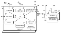
- FIG. 3A illustrates an exemplary embodiment of the IGRS 100 including one or more portable outdoor/indoor communication units 110 , 112 , (hereafter “field units”), in communication with one or more room units 120 , 125 .
- Each portable field unit 110 , 112 is carried, worn, or placed with an object to be tracked.
- each field unit 110 , 112 is incorporated into clothing worn by military personnel or attached to a utility belt like a hand-held radio.
- each field unit 110 , 112 is implemented as a standard laptop computer adapted to operate a described below.
- the control center 20 maintains a table that maps the identification of each field unit 110 , 112 with the particular object associated with that field unit 110 , 112 .
- Each room unit 120 , 125 is placed at a location, e.g., in a room within a building.
- a given location e.g., room
- each room unit 120 , 125 is portable for easy placement at the location. Such placement can occur in anticipation of or during a tracking situation.
- room units 120 , 125 can be installed in a structure similarly to the installing of smoke detectors in residential, commercial, and industrial buildings.
- Each room unit 120 , 125 can be connected to the electrical system of the structure or operate as battery powered units. If installed as part of the electrical system, the room units 120 , 125 can be wired together into a central computer (e.g., the base station 80 ).
- Each room unit 120 , 125 has a unique identification (e.g., a serial number), and includes an identification (ID) transmitter 121 .
- the control center 20 maintains a table that cross-references the serial numbers of the room unit 120 , 125 with the particular room in the structure where that room unit 120 , 125 is located.
- more than one portable field unit 110 , 112 can simultaneously occupy a given room and communicate with each room unit 120 , 125 placed in that room.
- Each portable field unit 110 , 112 includes a central processing unit (CPU) 125 in communication with a radio frequency (RF) modem 128 , a GPS receiver 132 , a display 136 , a user input device 138 , and an identification (ID) receiver 142 .
- the RF modem 128 is a data modem.
- the RF modem 128 transmits and receives voice information in addition to data.
- a power supply 146 provides power to the field unit 110 .
- the power supply 146 can be implemented as battery (e.g., two 12 volt batteries in parallel) or electrical power.
- the display 136 is a liquid crystal display that provides a user with the date and time, the indoor or outdoor location, and other status-related information.
- the user input device 138 enables the user to enter messages into the field unit 110 for transmission to the base station 80 .
- each field unit 110 , 112 further includes an interface 140 to communicate with other systems external to that field unit.
- each field unit 110 , 112 can receive signals for determining indoor and outdoor object positions of the object wearing, carrying, or accompanying that field unit 110 , 112 .
- the GPS receiver 132 To compute the outdoor position of an object, the GPS receiver 132 continually receives raw uncorrected GPS signals from the signal transmitters 94 and/or 98 .
- the RF modem 128 receives DGPS corrections from the base station 80 .
- the CPU 125 receives, parses, and forwards the DGPS corrections to the GPS receiver 132 over a serial port.
- the GPS receiver 132 computes corrected object positions and continuously returns the corrected object positions to the CPU 124 over the serial port.
- the CPU 124 updates the position on the display 136 and buffers the longitude and latitude information for transmission back to the base station 80 .
- the CPU 124 directs the RF modem 128 to transmit the corrected object position information to the base station 80 .
- the room unit 120 is placed at a predetermined location (indoors or outdoors) and the ID receiver 142 emits ultrasonic signals (i.e., pings) at pseudo-random intervals (e.g., in a range greater than 0 seconds and less than or equal to 2 seconds).
- ultrasonic signals i.e., pings
- pseudo-random intervals e.g., in a range greater than 0 seconds and less than or equal to 2 seconds.
- Other types of ultrasonic signals can be used, such as, for example, a whistle.
- the room unit 120 awakes from a sleep mode and the ID transmitter 121 prepares to transmit a signal that conveys identification information.
- the transmitted signal is an AM RF signal that includes a digitized serial number of the room unit.
- the ID transmitter 121 can transmit any type of coded signal (e.g., optical, ultrasonic, etc.) capable of conveying this serial number information.
- the ID receiver 142 receives the coded signal, decodes the serial number of the room unit 120 , and forwards this serial number to the CPU 124 .
- the CPU 124 through the RF modem 128 , sends the serial number to the base station 80 in the appropriate time slot and radio frequency as described below in connection with FIG. 7 .
- the time slot in which the serial number appears indicates to the base station 80 the particular field unit 110 , 112 with which the serial number is associated.
- the CPU 124 also sends information identifying the field unit 110 , 112 with the transmitted room unit serial number.
- the CPU 124 in one embodiment selects the indoor position for transmission to the base station 80 as described above.
- the base station 80 transmits the room unit serial number, and the identification of the field unit that transmitted the serial number, to the control center 120 . From the tables that map serial numbers to room locations and field unit identifications to objects, the control center 20 produces an association between the object to the particular room.
- a given room can have two or more room units 120 that detect and respond to an ultrasonic signal emitted by one field unit 110 . That field unit 110 accepts each reply from the room units 120 and reports the response time (relative to when the field unit 110 emitted the ultrasonic signal) for each of the room units 120 . If the precise positions of each of such room units 120 within the room are known, the base station 80 or control center 20 can calculate the approximate posture (e.g., standing, sitting, prostrate, etc.) of the object.
- the base station 80 or control center 20 can calculate the approximate posture (e.g., standing, sitting, prostrate, etc.) of the object.
- each field unit 110 , 112 can be incorporated with clothing worn by a tracked object, in part, because of the compact size of the units 110 , 112 .
- each field unit 110 , 112 is implemented in two boxes. One box houses the CPU 124 , the radio modem 128 , and the GPS receiver 132 and identification receiver 142 and approximates 50 cubic inches in size; the other box houses the GPS antenna 102 , the radio modem antenna 104 , and the ultrasonic sensor 145 , and the display 136 .
- the radio modem antenna 104 can operate as the antenna 144 for the ID receiver 142 and approximates 15 cubic inches in size.
- Such clothing is a laser tag vest worn by military personnel.
- This vest includes optical sensors for detecting lasers used as weapon fire during battle simulations.
- the vest produces a palpable vibration when the simulated weapon fire has hit the soldier wearing the vest.
- the field unit 110 incorporated in the vest includes an interface 140 in communication with the vest and with the CPU 124 .
- the interface 140 can also be used to notify the wearer of the field unit 110 of other events that occur during the battle simulation.
- the control center 20 may desire to communicate with the soldier that the soldier was wounded or killed in the simulated battle by an event other than by direct laser contact, such as an artillery attack in the location of the soldier.
- the base station 80 broadcasts the appropriate message to the RF modem 128 of the field unit 110 .
- the CPU 124 displays the message on the display 136 and causes the interface 140 to issue a message to the vest.
- the vest then produces the palpable vibration that alerts the soldier of the occurrence of an event.
- the soldier can then determine the type of event by reading the message in the display 136 .
- FIG. 3B illustrates an exemplary embodiment of the IGRS 100 ′ in which the field unit 110 ′ includes the ID transmitter 121 ′ and the room unit 120 ′ includes the ID receiver 142 ′.
- the other components of the IGRS 100 ′ are not shown, but are similar to components 124 , 128 , 132 , 136 , 138 , and 146 of IGRS 100 described above in FIG. 3 A.
- the room unit 120 ′ is in communication with the base station 80 (or another computer in communication with the base station 80 ) over a communication link 150 .
- This link 150 may be wired or wireless.
- the ID receiver 142 ′ of the room unit 120 ′ emits ultrasonic signals.
- the ID transmitter 121 ′ of that field unit 110 ′ issues an AM RF signal that includes digitized identification of the object.
- This identification can be, for example, the name of the object or a serial number associated with the field unit 110 ′.
- the signal emitted by the ID transmitter 121 ′ can be any signal capable of carrying a coded message.
- the ID receiver 142 ′ of the room unit 120 ′ receives the RF signal, decodes the identification information, and forwards this information to the base station 80 over the communication link 150 .
- the room unit 120 ′ transmits information identifying that room unit 120 ′ (i.e., the serial number of the room unit). From this identification information, the base station 80 determines that the object carrying (or accompanying) the field unit 110 ′ is in the room in which the room unit 120 ′ was placed.
- the field unit 110 ′ may transmit an outdoor object position, determined by the GPS receiver 132 ′, to the base station 80 while the room unit 120 ′ transmits the indoor object position.
- the base station 80 chooses which object position to report to the control center 20 .
- One embodiment gives priority to indoor object positions.
- the use of ultrasonic signals to initiate the communication between the room unit 120 , 125 , 120 ′, 125 ′ (hereafter, generally 120 ) and the field unit 110 , 112 , 110 ′, 112 ′ (hereafter, generally 110 ) operates to reduce the likelihood of false object position reports because these signals generally do not pass through walls. Thus, an ultrasonic signal emitted in one room is less likely to propagate to an adjacent room, hallway, or floor.
- Another technique to reduce false object position reports is for the ID receiver 142 , 142 ′ (hereafter, generally 142 ) to aperiodically emit the ultrasonic signals and then open a window of time during which any RF signal received in reply is accepted. Conversely, the ID receiver 142 ignores any RF signal arriving outside of the window of time.
- the aperiodic pattern in which each ID receiver 142 emits ultrasonic signals is determined pseudo-randomly and independently of every other ID receiver 142 .
- any two adjacent field units 110 in the embodiment of FIG. 3A, or any two adjacent room units 120 ′ in the embodiment of FIG. 3B are unlikely to have coincident open windows of time. Consequently, the possibility of an ID receiver 142 interpreting a RF signal from the wrong room as a response to an ultrasonic signal is decreased.
- the start of the window and the duration of the window are tuned for a desired distance between the ID transmitter 121 , 121 ′ (hereafter, generally 121 ) and the ID receiver 142 , 142 ′.
- the ID receiver 142 waits a predetermined period of time before opening the window of time to allow for the ultrasonic signal to propagate to the ID transmitter 121 .
- the desired distance is 15 feet
- the delay before the window of time opens approximates the time required for an ultrasonic signal to travel through 15 feet of air. Consequently, the possibility of false position reports is further diminished because the sender of the ultrasonic signal does not accept any RF signals until the delay expires, despite having initiated communication.
- the window of time remains open for a sufficient period to permit the timely return of the RF signal, which at the speed of light, occurs virtually instantaneously.
- the ID receiver 142 can require multiple successive, successful exchanges of ultrasonic and RF signals with the ID transmitter 121 before reporting that the object occupies the room.
- the ID receiver 142 (or in another embodiment the base station 80 ), counts the number of consecutive ultrasonic signals that the ID receiver 142 emitted without receiving a response from the ID transmitter 121 . In another embodiment, rather than count ultrasonic signals, the ID receiver 142 waits a predetermined period (e.g., 1 second). When a threshold period or count is exceeded, the ID receiver 142 is determined to have left the room.
- a predetermined period e.g. 1 second
- FIG. 4 shows an exemplary embodiment of each ID receiver 142 .
- the ID receiver 142 includes single electrical board 162 powered by a power supply 184 (here, a 9 volt battery).
- the electrical board 162 includes an ultrasonic transmitter 160 , a RF receiver 164 , a regulator 168 , a packet controller 172 , an oscillator 176 , and a processor 180 .
- the processor 180 controls when the ultrasonic transmitter 160 emits ultrasonic signals and determines identification information from identification signals received by the RF receiver 164 via the packet controller 172 .
- FIG. 5 shows an exemplary embodiment of each ID transmitter 121 .
- the ID transmitter 121 includes an electrical board 192 powered a power supply 216 (here, a 9 volt battery).
- the electrical board 192 includes an ultrasonic receiver 192 , a RF transmitter 196 , a regulator 200 , a packet controller 204 , an oscillator 208 , and a processor 212 .
- the processor 212 monitors the ultrasonic receiver 192 and sends the identification information via the packet controller 204 to the RF transmitter 196 when the ultrasonic receiver 192 detects an ultrasonic signal.
- FIG. 6 is a flow diagram illustrating a process by which the ID receiver 142 and ID transmitter 121 communicate in accordance with the principles of the invention.
- the ID receiver 142 aperiodically emits (step 250 ) an ultrasonic signal, and opens (step 254 ) a window of time having a limited duration for receiving a response to the ultrasonic signal from the other of the communication units.
- the ID receiver 142 waits a predetermined period of time before opening the window of time to allow for the ultrasonic signal to propagate to the ID transmitter 121 .
- the ID transmitter 121 receives (step 258 ) the ultrasonic signal and emits a RF signal in response.
- the RF signal includes identification information. If the ID transmitter 121 is part of the room unit 120 , then this identification information identifies the room unit. If the ID transmitter 121 is part of the field unit 110 accompanying the object, then the identification information identifies the object or the particular field unit 110 .
- the ID receiver 142 receives (step 262 ) the RF signal and accepts the response if the signal arrives within the window of time. Acceptance of the response creates an association between the identities of the room unit 120 and the tracked object; that is, the tracked object is deemed to be in the room having the room unit 120 .
- the ID receiver 142 subsequently reports (step 264 ) the identification information to the base station 80 .
- steps of 250 , 254 , 258 , and 262 must successfully occur multiple times in succession, with the receiver 142 obtaining the same identification information for both occurrences, before the ID receiver 142 reports that identification information to the base station 80 . If the RF signal arrives outside of the window of time, the ID receiver 142 ignores that signal.
- FIG. 7 shows an exemplary embodiment of the frequency and time slot allocation used by the base station 80 and each field unit 110 , 112 of the IGRS 100 when reporting object position information and exchanging messages.
- the base station 80 includes a computer 270 in communication with a plurality of master radios 280 , 280 ′ (generally 280 ). Each master radio 280 transmits and receives radio signals at a different predetermined frequency than every other master radio 280 .
- the field units 110 , 112 are organized into groups according to a predetermined frequency at which those field units 110 , 112 communicate with one of the master radios 280 . Some of the field units 110 , 112 communicate at frequency # 1 , others at frequency # 2 , and so on according to the number or master radios 280 at the base station 80 . Accordingly, each field unit 110 , 112 is in communication with one master radio 280 , and each master radio 280 is concurrently in communication with one group of field units, which includes one or more field units 110 , 112 concurrently communicating with that one master radio 280 .
- the base station 80 assigns a time slot for each field unit 110 , 112 and for the master radio 280 to use during a single reporting period 300 . Accordingly, by increasing the number of frequencies used or the reporting period 300 , the positioning system 30 can concurrently support almost an unlimited number of field units 110 .
- the master radio 280 communicates with field units 110 , 110 ′, and 110 ′ (generally 110 ) at frequency # 1 .
- the master radio 280 has time slot 284 during which to transfer information to each field unit 110 .
- the master radio 280 transmits information such as synchronization signals, text messages, and, in one embodiment, voice data.
- Each field unit 110 , 110 ′, 110 ′′ has a subsequent time slot 288 , 292 , 296 , respectively, during which to report position information (e.g., DGPS position information or the room unit serial number) and to send text messages to the master radio 280 of the base station 80 .
- position information e.g., DGPS position information or the room unit serial number
- the master radio 280 ′ communicates with field units 112 , 112 ′, and 112 ′ (generally 112 ) at frequency # 2 .
- the master radio 280 ′ has time slot 304 during which to transfer information to each field unit 120 , and each field unit 112 , 112 ′, 112 ′′ has a subsequent time slot 308 , 312 , 316 , respectively, during which to report position information to the master radio 280 ′ of the base station 80 .
- the base station 80 Because of the assignment of each field unit 110 to a particular time slot, the base station 80 is able to associate position information extracted from each time slot with a particular field unit 110 .
- the base station 80 relays the position information to the control center 20 .
- the control center 20 uses the position information to place each object within the context of a displayed map. In one embodiment, the positions of the objects are updated every thirty seconds.
- each hospital room has a room unit 120 installed and each patient or piece of equipment is fitted with a field unit 110 .
- a company could track the exact location of every person on its premises by installing room units 120 in all rooms and giving each employee or visitor a field unit 110 .
- This system would allow the company to monitor access to restricted areas, track down people for meetings, and dynamically route telephone calls to a person's current location.
Abstract
An integrated indoor and outdoor positioning system and method. A first communication unit aperiodically emits an ultrasonic signal. A second communication unit receives the ultrasonic signal and transmits an identification signal in response to receiving the ultrasonic signal. One of the two communication units is placed at a predetermined position and the other of the two communication units is placed with an object. Identification information obtained from the identification signal is used to determine position information indicating that the object is at the predetermined position. The first communication unit is placed at the predetermined position and the second communication unit accompanies the object. Alternatively, the first communication unit accompanies the object and the second communication unit is placed at the predetermined position. One of the two communication units may also include a GPS receiver for receiving GPS signals from a plurality of satellites or pseudolites and computing position information therefrom. The GPS receiver applies differential GPS corrections computed by a GPS reference receiver to improve the accuracy of the position information. Position information is transmitted to a base station over an assigned radio frequency and during a time slot allocated to the communication unit that is transmitting the position information.
Description
This invention was made with government support under Contract M67854-98-C-2098 awarded by the Marine Corps Warfighting Laboratory. The government has certain rights in the invention.
The invention relates generally to positioning systems. More specifically, the invention relates to positioning systems that integrate global positioning systems with indoor positioning systems.
Global positioning systems (GPS) are able to determine the relative position of an antenna coupled to a GPS receiver on or above the surface of the Earth. Twenty-four satellites placed in orbit around the Earth continuously transmit GPS signals on an L-band carrier (L1) frequency of 1.575 GHz. The L1 carrier component is modulated by a course acquisition (C/A) pseudo random noise (PRN) code component and a data component. The PRN code component provides timing information for determining when a satellite transmitted the GPS signal. The data component includes information such as the orbital position of the transmitting satellite. From the timing and satellite orbital position information in the PRN code and data components obtained from the GPS signals of at least four GPS satellites, the GPS receiver performs ranging measurements. By receiving four different GPS signals, the GPS receiver can determine the position of the antenna within meters.
To improve upon the accuracy of GPS, industry developed Differential GPS (DGPS), which is a variant of GPS that uses a fixed ground reference GPS receiver with a precisely known location to relay GPS corrections to a mobile GPS receiver. A general principle of DGPS is that satellite ranging errors affect the reference GPS receiver and mobile GPS receiver alike. Just like the mobile GPS receiver, the reference GPS receiver computes its position from the received GPS signals. The reference GPS receiver then detects ranging errors by comparing the computed position to the known position and computes corrections to these ranging errors for real-time transmission to the mobile GPS receiver. The reference GPS receiver can transmit the corrections using a tradition digital data link to the mobile GPS receiver. Consequently, the mobile GPS receiver applies the corrections to the measurements made from GPS signals received from the same set of satellites as the reference receiver to improve upon its own computed position measurement.
DGPS systems operate best when the antenna of the GPS receiver is outdoors to receive the GPS signals from the satellites (or pseudolites). GPS signals typically fade considerably or completely when penetrating the walls of structures, e.g., buildings. Consequently, a DGPS ceases to track an object bearing the antenna once that object enters indoors. Thus, there remains a need for a comprehensive positioning or tracking system that can track objects both indoors and outdoors.
An object of the invention is to integrate indoor tracking with outdoor tracking. Another object is to enable the tracking of multiple objects simultaneously without producing false position determinations. It is a further object of the invention to enable the tracking system to be portable.
One aspect of the invention features a system for determining a position of an object. The system includes a first communication unit that has a transmitter. The transmitter aperiodically emits an ultrasonic signal. A second communication unit has a receiver to receive the ultrasonic signal and a transmitter to transmit an identification signal in response to receiving the ultrasonic signal. One of the two communication units is placed at a predetermined position and the other of the two communication units is placed with an object. A processor uses identification information obtained from the identification signal to produce position information indicating that the object is at the predetermined position. In one embodiment, the first communication unit is placed at the predetermined position and the second communication unit accompanies the object. In another embodiment, the first communication unit accompanies the object and the second communication unit is placed at the predetermined position.
In one embodiment, the system includes a timer that produces a window of time and a receiver in communication with the timer. The receiver accepts any identification signal that arrives within the window of time and ignores any identification signal that arrives outside of the window of time. The timer opens the window of time a predetermined period of time after the transmitter of the first communication unit emits the ultrasonic signal. As an example, the predetermined period of time approximates a period of time required for the ultrasonic signal to propagate to the second communication unit.
The information conveyed by the identification signal depends upon the particular embodiment. In one embodiment, the identification signal includes information that leads to identifying the predetermined position. For example, the identification signal in this embodiment includes the serial number of the communication unit that transmits the identification signal. A control station maintains a table that cross-references serial numbers of communication units to particular positions where each communication unit is located.
In another embodiment, the identification signal includes information that leads to identifying the object at the predetermined position. Again, the identification signal includes the serial number of the communication unit that transmits the identification signal. A control station maintains a table that cross-references serial numbers of communication units to particular objects accompanying that communication unit.
In another embodiment, the system includes a differential global positioning system (DGPS) that is capable of computing a position of the object from GPS signals received from remote signal transmitters.
In another aspect, the invention features a method for tracking an object. A first communication unit is placed at a predetermined position and a second communication unit accompanies the object. An ultrasonic signal is aperiodically emitted from one of the communication units. A window of time having a limited duration is opened for receiving a response to the ultrasonic signal from the other of the communication units. The response to the ultrasonic signal is accepted if the response arrives within the opened window of time. The predetermined position is associated with the object based on information provided with the response.
In one embodiment, position information of the object is computed from GPS signals received from a plurality of remote signal transmitters using a differential global positioning system (DGPS). In another embodiment, a frequency is assigned to one of the communication units for communicating with a base station and a time slot is allocated within the assigned frequency during which that one communication unit can transmit position information to the base station. In still another embodiment, the ultrasonic signal is detected at more than one position, and an approximate position of the object is calculated based in part on when the ultrasonic signal was detected at each position.
In another aspect, the invention features a system for tracking a position of an object that includes a global positioning system that computes position information about the object when the global positioning system is able to receive signals from a signal transmitter. An indoor tracking system that includes a communication unit placed at a predetermined position, determines position information about the object when the object enters within a predetermined range of the communication unit. A processor receives the position information about the object for transmission to a base station.
In another aspect, the invention features a portable apparatus that accompanies an object and is used for determining a position of the object. A transceiver is placed at a predetermined location. The apparatus includes a global positioning system (GPS) receiver that computes the position of the object from signals concurrently received from a plurality of signal transmitters. A communication unit exchanges ultrasonic and radio frequency signals with a transceiver to determine the position of the object when the object is within range of the transceiver. This transceiver is placed at a predetermined location. A processor receives position information determined by either or both of the GPS receiver and the communication unit.
The above and further objects, features, and advantages of the invention will become clear from the following detailed description when read with reference to the accompanying drawings in which:
FIG. 1 is a block diagram of an indoor and outdoor object tracking system embodying the principles of the invention;
FIG. 2 is a diagram of an embodiment of the tracking system of FIG. 1, including a base station, integrated global positioning system (GPS) radio system, and a control center;
FIGS. 3A and 3B are block diagrams of embodiments of the integrated GPS radio system (IGRS), each embodiment including an ID transmitter and an ID receiver;
FIG. 4 is an exemplary block diagram of the ID receiver;
FIG. 5 is an exemplary block diagram of the ID transmitter;
FIG. 6 is a flow diagram illustrating a process by which the ID receiver and ID transmitter communicate in accordance with the principles of the invention; and
FIG. 7 is a block diagram illustrating frequency allocation and time slot assignments for exchanging object position information and messages between the base station and each portable communication unit of the IGRS.
FIG. 1 shows a tracking system 10 including a control center 20 in communication with a positioning system 30 to track objects indoors and outdoors in accordance with the principles of the invention. In general, an object is a person, animal, or thing that moves or can be moved. Examples of objects include individuals (e.g., children, soldiers, firefighters, law enforcement officers, and rescue personnel), domestic and wild animals, vehicles (e.g., automobiles, ships, aircraft, rail systems, etc.), and inventory, etc. As described in more detail below, the tracking system 10 is capable of simultaneously tracking the positions (or locations) of numerous objects in real-time. For example, during an experimental test, the tracking system 10 concurrently tracked the positions of 700 military personnel.
The positioning system 30 integrates an indoor tracking system 40 with a differentially corrected global positioning system (DGPS) 50 to achieve indoor and outdoor tracking, respectively. An information relay 60 is in communication with the indoor tracking system 40 and the DGPS 50 to receive object position information produced by the indoor tracking system 40 and the DGPS 50 and to forward such position information to the control center 20.
The information relay 60 is also in communication with a messaging system 70. In some applications embodying the invention, the control center 20 may want to convey information to the tracked object. For example, in a war game situation in which the tracking system 10 is used to track soldiers on a mock battlefield, the control center 20 can exchange messages with each soldier equipped with the messaging system 70 through the information relay 60. In the embodiment shown, the positioning system 30 includes the information relay 60 and the messaging system 70; in other embodiments, either or both of the information relay 60 and messaging system 70 can be separate from the positioning system 30.
In brief overview, the positioning system 30 simultaneously and continuously determines the indoor and outdoor positions of a plurality of objects in real-time. The continuous position determinations enable the tracking of the movement of each object. To achieve this tracking, each tracked object is equipped with a portable unit (described in more detail below) that achieves the functionality of the indoor tracking system 40 and with the DGPS 50.
While an object is outdoors, the DGPS 50 can usually compute the position of that object and send the object position information to the information relay 60. Such object position information includes longitude and latitude values identifying the geographical location of the tracked object. The ability of the DGPS 50 to track the object diminishes and typically ceases when the object moves into a structure, such as a building. In accordance with the principles of the invention, the indoor tracking system 40 takes over where the capabilities of the DGPS 50 leave off by determining the position of each object that moves into that structure. Although suited for indoor tracking, the indoor tracking system 40 can be deployed outdoors to supplement the tracking capabilities of the DGPS 50. (Hereafter, references to indoor object positions mean those object positions determined by the indoor tracking system 40, irrespective of whether the object is actually indoors. References to outdoor object positions mean those object positions determined by the DGPS 50.)
The object position information produced by the indoor tracking system 40 also passes to the information relay 60. In one embodiment, the information relay 60 chooses between the object position information concurrently produced by the DGPS 50 and the indoor tracking system 40 for a given object. For example, in one embodiment the information relay 60 prioritizes indoor object position information over outdoor object position information. Thus, when indoor and outdoor object position information are concurrently available for the given object, the information relay 60 sends only the indoor object position information to the control center 20.
The control center 20 maintains the current position information for every tracked object. To facilitate the tracking of the objects, the control center 20 displays the position information on a computer screen, e.g., by displaying a map and placing each object on that map.
FIG. 2 shows an exemplary embodiment of the tracking system 10 of FIG. 1. In this embodiment, the control center 20 includes a computer system 24 operating as a gateway to a local area network (LAN) 26. The positioning system 30 includes a base station 80 in communication with a GPS reference receiver 90 and an integrated GPS radio system (IGRS) 100. The GPS reference receiver 90 and the IGRS 100 each include a GPS antenna 92, 102, respectively, to receive GPS signals from signal transmitters such as satellites 94 and/or ground-based signal transmitters (i.e., pseudolites) 98. As described in more detail below, the IGRS 100 supports the concurrent tracking of a plurality of objects. Each object tracked by the positioning system 30 is equipped with a portable communication unit that is part of the IGRS 100. Specifically, the IGRS 100 includes a GPS antenna 102 for each tracked object.
The IGRS 100 and the GPS reference receiver 90 receive GPS signals from the same set of at least four signal transmitters 94, 98. The GPS reference receiver 90 is situated at a precisely known location and, consequently, computes corrections for satellite ranging errors detected in the received GPS signals as is known in the art. The corrections pass from the GPS reference receiver 90 to the base station 80 over communication link 86.
In one embodiment, the base station 80 is stationary (i.e., at a fixed location) and includes at least one radio antenna 82 to communicate with one or more radio antenna(s) 104 of the IGRS 100. Each tracked object is associated with one of the radio antenna(s) 104. As described further in connection with FIG. 7, each object communicates by radio with the base station 80 to exchange messages, object position information, and corrections.
The base station 80 is also in communication with the control center 20 over a communication link 84 to transfer object position information and to receive messages directed to the objects. The communication link 84 can be one of a variety of connections including standard telephone lines, LAN or WAN links (e.g., T1, T3, 56 kb, X.25), broadband connections (ISDN, Frame Relay, ATM), and wireless connections.
During operation, the GPS reference receiver 90 receives GPS signals from the signal transmitters 94 and computes the position of the GPS reference receiver 90 from the received GPS signals. The GPS reference receiver 90 then computes differential corrections to the satellite ranging errors from the computed position and the known positions of the GPS reference receiver 90, and forwards the computed corrections to the base station 80. The base station 80 then transmits GPS differential corrections to each object tracked by the IGRS 100 over at least one predetermined radio frequency.
Each object tracked by the IGRS 100 also receives the GPS signals received by the associated antenna 102 from the signal transmitters 94 and the GPS differential corrections from the base station 80. From the GPS signals, each object computes its own position, using the differential corrections to improve the accuracy of the computed position (hereafter referred to as the DGPS position). For each object that is in an appropriately equipped structure, as described in more detail below, the IGRS 100 also produces indoor object position information for that object in accordance with the principles of the invention. The IGRS 100 sends the DGPS and indoor object position information to the base station 80 by radio transmission as described in more detail below. The base station 80 reports the object position information to the control center 20 over the communication link 84.
FIG. 3A illustrates an exemplary embodiment of the IGRS 100 including one or more portable outdoor/ indoor communication units 110, 112, (hereafter “field units”), in communication with one or more room units 120, 125. Each portable field unit 110, 112 is carried, worn, or placed with an object to be tracked. For example, in one embodiment, each field unit 110, 112 is incorporated into clothing worn by military personnel or attached to a utility belt like a hand-held radio. In another embodiment, each field unit 110, 112 is implemented as a standard laptop computer adapted to operate a described below. The control center 20 maintains a table that maps the identification of each field unit 110, 112 with the particular object associated with that field unit 110, 112.
Each room unit 120, 125, is placed at a location, e.g., in a room within a building. A given location (e.g., room) can have more than one room unit 120, 125. In general, each room unit 120, 125 is portable for easy placement at the location. Such placement can occur in anticipation of or during a tracking situation. For example, room units 120, 125 can be installed in a structure similarly to the installing of smoke detectors in residential, commercial, and industrial buildings. Each room unit 120, 125 can be connected to the electrical system of the structure or operate as battery powered units. If installed as part of the electrical system, the room units 120, 125 can be wired together into a central computer (e.g., the base station 80).
Each room unit 120, 125 has a unique identification (e.g., a serial number), and includes an identification (ID) transmitter 121. The control center 20 maintains a table that cross-references the serial numbers of the room unit 120, 125 with the particular room in the structure where that room unit 120, 125 is located.
In accordance with the principles of the invention, more than one portable field unit 110, 112 can simultaneously occupy a given room and communicate with each room unit 120, 125 placed in that room. Each portable field unit 110, 112 includes a central processing unit (CPU) 125 in communication with a radio frequency (RF) modem 128, a GPS receiver 132, a display 136, a user input device 138, and an identification (ID) receiver 142. In one embodiment, the RF modem 128 is a data modem. In another embodiment, the RF modem 128 transmits and receives voice information in addition to data. A power supply 146 provides power to the field unit 110. The power supply 146 can be implemented as battery (e.g., two 12 volt batteries in parallel) or electrical power. In one embodiment, the display 136 is a liquid crystal display that provides a user with the date and time, the indoor or outdoor location, and other status-related information. The user input device 138 enables the user to enter messages into the field unit 110 for transmission to the base station 80.
In one embodiment, described in more detail below, each field unit 110, 112, further includes an interface 140 to communicate with other systems external to that field unit.
During operation, each field unit 110, 112 can receive signals for determining indoor and outdoor object positions of the object wearing, carrying, or accompanying that field unit 110, 112. To compute the outdoor position of an object, the GPS receiver 132 continually receives raw uncorrected GPS signals from the signal transmitters 94 and/or 98. The RF modem 128 receives DGPS corrections from the base station 80. The CPU 125 receives, parses, and forwards the DGPS corrections to the GPS receiver 132 over a serial port. The GPS receiver 132 computes corrected object positions and continuously returns the corrected object positions to the CPU 124 over the serial port. The CPU 124 updates the position on the display 136 and buffers the longitude and latitude information for transmission back to the base station 80. At a specified time, described in more detail in connection with FIG. 7, the CPU 124 directs the RF modem 128 to transmit the corrected object position information to the base station 80.
To determine the indoor position of an object, the room unit 120 is placed at a predetermined location (indoors or outdoors) and the ID receiver 142 emits ultrasonic signals (i.e., pings) at pseudo-random intervals (e.g., in a range greater than 0 seconds and less than or equal to 2 seconds). Other types of ultrasonic signals can be used, such as, for example, a whistle. Upon detecting an ultrasonic signal, the room unit 120 awakes from a sleep mode and the ID transmitter 121 prepares to transmit a signal that conveys identification information. In one embodiment, the transmitted signal is an AM RF signal that includes a digitized serial number of the room unit. In general, the ID transmitter 121 can transmit any type of coded signal (e.g., optical, ultrasonic, etc.) capable of conveying this serial number information.
The ID receiver 142 receives the coded signal, decodes the serial number of the room unit 120, and forwards this serial number to the CPU 124. The CPU 124, through the RF modem 128, sends the serial number to the base station 80 in the appropriate time slot and radio frequency as described below in connection with FIG. 7. The time slot in which the serial number appears indicates to the base station 80 the particular field unit 110, 112 with which the serial number is associated. In another embodiment, the CPU 124 also sends information identifying the field unit 110, 112 with the transmitted room unit serial number.
In the event the CPU 124 concurrently receives an outdoor position from the GPS receiver 132 and an indoor position from the identification receiver 142, the CPU 124 in one embodiment selects the indoor position for transmission to the base station 80 as described above.
The base station 80 transmits the room unit serial number, and the identification of the field unit that transmitted the serial number, to the control center 120. From the tables that map serial numbers to room locations and field unit identifications to objects, the control center 20 produces an association between the object to the particular room.
In one embodiment, a given room can have two or more room units 120 that detect and respond to an ultrasonic signal emitted by one field unit 110. That field unit 110 accepts each reply from the room units 120 and reports the response time (relative to when the field unit 110 emitted the ultrasonic signal) for each of the room units 120. If the precise positions of each of such room units 120 within the room are known, the base station 80 or control center 20 can calculate the approximate posture (e.g., standing, sitting, prostrate, etc.) of the object.
As described above, in one embodiment each field unit 110, 112 can be incorporated with clothing worn by a tracked object, in part, because of the compact size of the units 110, 112. In one embodiment, each field unit 110, 112 is implemented in two boxes. One box houses the CPU 124, the radio modem 128, and the GPS receiver 132 and identification receiver 142 and approximates 50 cubic inches in size; the other box houses the GPS antenna 102, the radio modem antenna 104, and the ultrasonic sensor 145, and the display 136. The radio modem antenna 104 can operate as the antenna 144 for the ID receiver 142 and approximates 15 cubic inches in size.
An example of such clothing is a laser tag vest worn by military personnel. This vest includes optical sensors for detecting lasers used as weapon fire during battle simulations. Generally, the vest produces a palpable vibration when the simulated weapon fire has hit the soldier wearing the vest. For this embodiment, the field unit 110 incorporated in the vest includes an interface 140 in communication with the vest and with the CPU 124.
During a mock battle, laser light that strikes one of the optical sensors simulates a wound inflicted by weapon fire. The vest produces the palpable vibration that alerts the soldier of the event. When the laser hits the soldier, the triggered optical sensor notifies the interface 140. The interface 140 then communicates the event to the CPU 124, and the CPU 124 displays a text message to the soldier on the display 136 indicating the simulated result of the hit (e.g., wounded or killed in action).
The interface 140 can also be used to notify the wearer of the field unit 110 of other events that occur during the battle simulation. For example, the control center 20 may desire to communicate with the soldier that the soldier was wounded or killed in the simulated battle by an event other than by direct laser contact, such as an artillery attack in the location of the soldier. In this situation, the base station 80 broadcasts the appropriate message to the RF modem 128 of the field unit 110. The CPU 124 displays the message on the display 136 and causes the interface 140 to issue a message to the vest. The vest then produces the palpable vibration that alerts the soldier of the occurrence of an event. The soldier can then determine the type of event by reading the message in the display 136.
FIG. 3B illustrates an exemplary embodiment of the IGRS 100′ in which the field unit 110′ includes the ID transmitter 121′ and the room unit 120′ includes the ID receiver 142′. The other components of the IGRS 100′ are not shown, but are similar to components 124, 128, 132, 136, 138, and 146 of IGRS 100 described above in FIG. 3A. In this embodiment, the room unit 120′ is in communication with the base station 80 (or another computer in communication with the base station 80) over a communication link 150. This link 150 may be wired or wireless.
In this embodiment, the ID receiver 142′ of the room unit 120′ emits ultrasonic signals. When the object carrying the field unit 110′, 112′ enters the room and detects the ultrasonic signal, the ID transmitter 121′ of that field unit 110′ issues an AM RF signal that includes digitized identification of the object. This identification can be, for example, the name of the object or a serial number associated with the field unit 110′. Again, the signal emitted by the ID transmitter 121′ can be any signal capable of carrying a coded message. The ID receiver 142′ of the room unit 120′ receives the RF signal, decodes the identification information, and forwards this information to the base station 80 over the communication link 150. Along with the information identifying the object, the room unit 120′ transmits information identifying that room unit 120′ (i.e., the serial number of the room unit). From this identification information, the base station 80 determines that the object carrying (or accompanying) the field unit 110′ is in the room in which the room unit 120′ was placed.
Conceivably the field unit 110′ may transmit an outdoor object position, determined by the GPS receiver 132′, to the base station 80 while the room unit 120′ transmits the indoor object position. In this embodiment, the base station 80 chooses which object position to report to the control center 20. One embodiment gives priority to indoor object positions.
Time-Gated Window The embodiments of the IGRS 100 and 100′ shown in FIGS. 3A and 3B, respectively, support the simultaneous tracking of multiple objects. Simultaneous tracking of multiple objects introduces the possibility of reporting false object positions because every ID transmitter 121 and ID receiver 142 operates on the same radio frequency. A false report might occur if an object successfully exchanges ultrasonic and RF signals with a room that the object does not actually occupy. For example, the object might instead be in an adjacent room, on an adjacent floor, in a hallway, or moving past a window just outside the room, from which position the exchanged ultrasonic and RF signals successfully reach their respective destinations.
The use of ultrasonic signals to initiate the communication between the room unit 120, 125, 120′, 125′ (hereafter, generally 120) and the field unit 110, 112, 110′, 112′ (hereafter, generally 110) operates to reduce the likelihood of false object position reports because these signals generally do not pass through walls. Thus, an ultrasonic signal emitted in one room is less likely to propagate to an adjacent room, hallway, or floor.
Another technique to reduce false object position reports is for the ID receiver 142, 142′ (hereafter, generally 142) to aperiodically emit the ultrasonic signals and then open a window of time during which any RF signal received in reply is accepted. Conversely, the ID receiver 142 ignores any RF signal arriving outside of the window of time. The aperiodic pattern in which each ID receiver 142 emits ultrasonic signals is determined pseudo-randomly and independently of every other ID receiver 142. Thus, any two adjacent field units 110 in the embodiment of FIG. 3A, or any two adjacent room units 120′ in the embodiment of FIG. 3B, are unlikely to have coincident open windows of time. Consequently, the possibility of an ID receiver 142 interpreting a RF signal from the wrong room as a response to an ultrasonic signal is decreased.
Further, in one embodiment the start of the window and the duration of the window are tuned for a desired distance between the ID transmitter 121, 121′ (hereafter, generally 121) and the ID receiver 142, 142′. For example, the ID receiver 142 waits a predetermined period of time before opening the window of time to allow for the ultrasonic signal to propagate to the ID transmitter 121. In this example, if the desired distance is 15 feet, the delay before the window of time opens approximates the time required for an ultrasonic signal to travel through 15 feet of air. Consequently, the possibility of false position reports is further diminished because the sender of the ultrasonic signal does not accept any RF signals until the delay expires, despite having initiated communication. As for duration, the window of time remains open for a sufficient period to permit the timely return of the RF signal, which at the speed of light, occurs virtually instantaneously.
To further reduce false reports of object positions, the ID receiver 142 can require multiple successive, successful exchanges of ultrasonic and RF signals with the ID transmitter 121 before reporting that the object occupies the room.
To determine that an object has left the room, the ID receiver 142 (or in another embodiment the base station 80), counts the number of consecutive ultrasonic signals that the ID receiver 142 emitted without receiving a response from the ID transmitter 121. In another embodiment, rather than count ultrasonic signals, the ID receiver 142 waits a predetermined period (e.g., 1 second). When a threshold period or count is exceeded, the ID receiver 142 is determined to have left the room.
FIG. 4 shows an exemplary embodiment of each ID receiver 142. The ID receiver 142 includes single electrical board 162 powered by a power supply 184 (here, a 9 volt battery). The electrical board 162 includes an ultrasonic transmitter 160, a RF receiver 164, a regulator 168, a packet controller 172, an oscillator 176, and a processor 180. The processor 180 controls when the ultrasonic transmitter 160 emits ultrasonic signals and determines identification information from identification signals received by the RF receiver 164 via the packet controller 172.
FIG. 5 shows an exemplary embodiment of each ID transmitter 121. The ID transmitter 121 includes an electrical board 192 powered a power supply 216 (here, a 9 volt battery). The electrical board 192 includes an ultrasonic receiver 192, a RF transmitter 196, a regulator 200, a packet controller 204, an oscillator 208, and a processor 212. The processor 212 monitors the ultrasonic receiver 192 and sends the identification information via the packet controller 204 to the RF transmitter 196 when the ultrasonic receiver 192 detects an ultrasonic signal.
FIG. 6 is a flow diagram illustrating a process by which the ID receiver 142 and ID transmitter 121 communicate in accordance with the principles of the invention. The ID receiver 142 aperiodically emits (step 250) an ultrasonic signal, and opens (step 254) a window of time having a limited duration for receiving a response to the ultrasonic signal from the other of the communication units. In one embodiment, the ID receiver 142 waits a predetermined period of time before opening the window of time to allow for the ultrasonic signal to propagate to the ID transmitter 121.
The ID transmitter 121 receives (step 258) the ultrasonic signal and emits a RF signal in response. The RF signal includes identification information. If the ID transmitter 121 is part of the room unit 120, then this identification information identifies the room unit. If the ID transmitter 121 is part of the field unit 110 accompanying the object, then the identification information identifies the object or the particular field unit 110.
The ID receiver 142 receives (step 262) the RF signal and accepts the response if the signal arrives within the window of time. Acceptance of the response creates an association between the identities of the room unit 120 and the tracked object; that is, the tracked object is deemed to be in the room having the room unit 120. The ID receiver 142 subsequently reports (step 264) the identification information to the base station 80.
In one embodiment, steps of 250, 254, 258, and 262 must successfully occur multiple times in succession, with the receiver 142 obtaining the same identification information for both occurrences, before the ID receiver 142 reports that identification information to the base station 80. If the RF signal arrives outside of the window of time, the ID receiver 142 ignores that signal.
FIG. 7 shows an exemplary embodiment of the frequency and time slot allocation used by the base station 80 and each field unit 110, 112 of the IGRS 100 when reporting object position information and exchanging messages. As shown, the base station 80 includes a computer 270 in communication with a plurality of master radios 280, 280′ (generally 280). Each master radio 280 transmits and receives radio signals at a different predetermined frequency than every other master radio 280.
The field units 110, 112 are organized into groups according to a predetermined frequency at which those field units 110, 112 communicate with one of the master radios 280. Some of the field units 110, 112 communicate at frequency # 1, others at frequency # 2, and so on according to the number or master radios 280 at the base station 80. Accordingly, each field unit 110, 112 is in communication with one master radio 280, and each master radio 280 is concurrently in communication with one group of field units, which includes one or more field units 110, 112 concurrently communicating with that one master radio 280. To enable the exchange of information between each such field unit 110, 112 and that master radio 280 at a particular frequency, the base station 80 assigns a time slot for each field unit 110, 112 and for the master radio 280 to use during a single reporting period 300. Accordingly, by increasing the number of frequencies used or the reporting period 300, the positioning system 30 can concurrently support almost an unlimited number of field units 110.
In the example shown in FIG. 7, the master radio 280 communicates with field units 110, 110′, and 110′ (generally 110) at frequency # 1. The master radio 280 has time slot 284 during which to transfer information to each field unit 110. During the time slot 284, the master radio 280 transmits information such as synchronization signals, text messages, and, in one embodiment, voice data. Each field unit 110, 110′, 110″ has a subsequent time slot 288, 292, 296, respectively, during which to report position information (e.g., DGPS position information or the room unit serial number) and to send text messages to the master radio 280 of the base station 80.
Also shown in FIG. 7, the master radio 280′ communicates with field units 112, 112′, and 112′ (generally 112) at frequency # 2. The master radio 280′ has time slot 304 during which to transfer information to each field unit 120, and each field unit 112, 112′, 112″ has a subsequent time slot 308, 312, 316, respectively, during which to report position information to the master radio 280′ of the base station 80.
Because of the assignment of each field unit 110 to a particular time slot, the base station 80 is able to associate position information extracted from each time slot with a particular field unit 110. The base station 80 relays the position information to the control center 20. The control center 20 uses the position information to place each object within the context of a displayed map. In one embodiment, the positions of the objects are updated every thirty seconds.
The principles of the invention are applicable to a variety of uses. For example, hospitals can use the principles of the invention to keep track of patients and high-value equipment within the facility. Here, each hospital room has a room unit 120 installed and each patient or piece of equipment is fitted with a field unit 110.
In another example, a company could track the exact location of every person on its premises by installing room units 120 in all rooms and giving each employee or visitor a field unit 110. This system would allow the company to monitor access to restricted areas, track down people for meetings, and dynamically route telephone calls to a person's current location.
While the invention has been shown and described with reference to specific preferred embodiments, it should be understood by those skilled in the art that various changes in form and detail may be made therein without departing from the spirit and scope of the invention as defined by the following claims.
Claims (34)
1. A system for determining a position of an object, comprising:
a first communication unit having a transmitter that emits a sound signal; and
a second communication unit having a receiver to receive the sound signal and a transmitter to transmit a responsive identification signal,
wherein one of the two communication units is placed at a predetermined position and the other of the two communication units is placed with an object, and
wherein the object is identified as being located at the predetermined position if the two communication units establish communications by exchanging the sound and identification signals.
2. The system of claim 1 further comprising:
a timer producing a window of time;
a receiver in the first communication unit in communication with the timer, the receiver accepting any identification signal that arrives within the window of time and ignoring any identification signal that arrives outside of the window of time.
3. The system of claim 2 wherein the timer opens the window of time a predetermined period of time after the transmitter of the first communication unit emits the sound signal.
4. The system of claim 3 wherein the predetermined period of time approximates a period of time required for the sound signal to propagate to the second communication unit.
5. The system of claim 1 wherein the first communication unit is placed at the predetermined position and the second communication unit accompanies the object.
6. The system of claim 1 wherein the first communication unit accompanies the object and the second communication unit is placed at the predetermined position.
7. The system of claim 1 wherein the identification signal is a radio frequency (RF) signal.
8. The system of claim 1 wherein the identification signal includes information that leads to identifying the predetermined position.
9. The system of claim 1 wherein the identification signal includes information that leads to identifying the object.
10. The system of claim 1 wherein the identification signal includes information related to an identity of the object and further comprising a processor in communication with one of the communication units to receive the identification signal and use the identification information in the identification signal to produce position information indicating that the object is at the predetermined position.
11. The system of claim 10 further comprising a differential global positioning system (DGPS), in communication with the processor, capable of computing a position of the object from GPS signals received from remote signal transmitters.
12. The system of claim 10 wherein one of the two communication units includes a second transmitter in communication with the processor, the second transmitter transmitting the position information to a base station.
13. The system of claim 12 wherein the first communication unit includes the second transmitter that transmits the position information to the base station.
14. The system of claim 1 further comprising a base station in communication with one of the communication units to receive the position information obtained by that communication unit.
15. The system of claim 1 wherein the sound signal is an ultrasonic signal.
16. The system of claim 1 wherein the transmitter transmits sound signals aperiodically.
17. A method for tracking an object in a system having a first communication unit placed at a predetermined position and a second communication unit placed with the object, the method comprising:
(a) emitting a sound signal from one of the communication units;
(b) opening a window of time having a limited duration for receiving a response to the sound signal from the other of the communication units;
(c) accepting the response to the sound signal if the response arrives within the opened window of time; and
(d) associating the predetermined position with the object based on information provided with the response.
18. The method of claim 17 further comprising:
waiting a predetermined period of time before opening the window of time to allow for the sound signal to propagate to the other of the communication units.
19. The method of claim 17 further comprising:
computing position information of the object from GPS signals received from a plurality of remote signal transmitters using a differential global positioning system (DGPS).
20. The method of claim 17 further comprising:
assigning a frequency to one of the communication units for communicating with a base station; and
allocating a time slot within the assigned frequency during which that one communication unit can transmit position information to the base station.
21. The method of claim 17 further comprising:
detecting the sound signal at more than one position; and
calculating an approximate position of the object based in part on when the sound signal was detected at each position.
22. The method of claim 17 further comprising receiving a radio frequency (RF) signal as the response to the sound signal.
23. The method of claim 17 further comprising repeating the emitting, the opening, and the accepting before associating the predetermined position with the object.
24. The method of claim 17 wherein the emitting of the sound signal occurs aperiodically.
25. A method for tracking a plurality of objects in a system having a first communication unit placed at a predetermined position and a plurality of second communication units each accompanying a respective object from the plurality of objects, the method comprising:
(a) emitting a sound signal from each of the second communication units;
(b) opening a window of time having limited duration by each of the second communication units in response to emitting the sound signal; and
(c) accepting by each second communication unit a response to the sound signal emitted by such second communication unit if that response arrives within the window of time opened by that second communication unit and ignoring any response that arrives outside of that window of time.
26. The method of claim 25 , further comprising:
determining position information by each of the second communication units; and
assigning one of a plurality of frequencies to each of the second communication units for transmitting the position information determined by that second communication unit; and
allocating a time slot to each of the second communication units within the frequency assigned to that second communication unit during which that second communication unit can transmit the determined position information.
27. The method of claim 25 wherein the emitting of the sound signal occurs aperiodically.
28. A system for tracking a position of an object, comprising:
a global positioning system accompanying the object, the global positioning system computing position information about the object when the global positioning system is able to receive signals from a signal transmitter; and
an indoor tracking system including a communication unit placed at a predetermined position, the indoor tracking system determining position information about the object when the object enters within a predetermined range of the communication unit by communicating with a communication unit located with the object using sound signaling.
29. The system of claim 28 further comprising a processor in communication with the global positioning and the indoor tracking systems to receive position information about the object.
30. In a system including a transceiver placed at a predetermined location, a portable apparatus accompanying an object used for determining a position of the object, comprising:
a global positioning system (GPS) receiver computing the position of the object from signals concurrently received from a plurality of signal transmitters; and
a communication unit exchanging sound and radio frequency signals with the transceiver to determine the position of the object when the object is within range of the transceiver.
31. The portable apparatus of claim 30 wherein the communication unit comprises:
an ultrasonic transmitter aperiodically emitting an ultrasonic signal; and
a radio frequency (RF) modem receiving an identification signal from the transceiver in response to the emitted ultrasonic signal.
32. The portable apparatus of claim 30 wherein the communication unit comprises:
a receiver receiving an ultrasonic signal emitted by the transceiver; and
a radio frequency (RF) modem transmitting an identification signal in response to the received sound signal.
33. The portable apparatus of claim 30 further comprising a radio frequency (RF) modem exchanging signals with a second transceiver.
34. The portable apparatus of claim 30 wherein the exchanged signals represent voice data.
Priority Applications (1)
| Application Number | Priority Date | Filing Date | Title |
|---|---|---|---|
| US09/517,897 US6459989B1 (en) | 2000-03-03 | 2000-03-03 | Portable integrated indoor and outdoor positioning system and method |
Applications Claiming Priority (1)
| Application Number | Priority Date | Filing Date | Title |
|---|---|---|---|
| US09/517,897 US6459989B1 (en) | 2000-03-03 | 2000-03-03 | Portable integrated indoor and outdoor positioning system and method |
Publications (1)
| Publication Number | Publication Date |
|---|---|
| US6459989B1 true US6459989B1 (en) | 2002-10-01 |
Family
ID=24061681
Family Applications (1)
| Application Number | Title | Priority Date | Filing Date |
|---|---|---|---|
| US09/517,897 Expired - Fee Related US6459989B1 (en) | 2000-03-03 | 2000-03-03 | Portable integrated indoor and outdoor positioning system and method |
Country Status (1)
| Country | Link |
|---|---|
| US (1) | US6459989B1 (en) |
Cited By (82)
| Publication number | Priority date | Publication date | Assignee | Title |
|---|---|---|---|---|
| US20020022490A1 (en) * | 2000-04-20 | 2002-02-21 | Nec Corporation | Mobile telephone system capable of effectively utilizing GPS information even if direct reception by a mobile telephone apparatus is difficult |
| US20020111201A1 (en) * | 2001-02-13 | 2002-08-15 | Lang Brook W. | Location-based game system |
| US20030050089A1 (en) * | 2001-09-13 | 2003-03-13 | Denso Corporation | Mobile station having indoor/outdoor mode shifting function |
| US20030069025A1 (en) * | 2001-10-09 | 2003-04-10 | General Electric Company | Transmitter location for ultra-wideband, transmitted-reference CDMA communication system |
| US6658348B2 (en) * | 2001-10-09 | 2003-12-02 | Hewlett-Packard Development Company, L.P. | Systems and methods for providing information to users |
| US6720922B2 (en) * | 2002-03-29 | 2004-04-13 | Microsoft Corporation | Radio-frequency badge for location measurement |
| US20040111195A1 (en) * | 2002-06-11 | 2004-06-10 | Vries Jeroen Joost De | Systems and methods for marine satellite monitoring |
| US20040242249A1 (en) * | 2003-05-30 | 2004-12-02 | Neilson Paul Christian | Non-interfering multipath communications systems |
| US20050021369A1 (en) * | 2003-07-21 | 2005-01-27 | Mark Cohen | Systems and methods for context relevant information management and display |
| US6958701B1 (en) * | 2002-06-05 | 2005-10-25 | Storkamp John D | Transportation monitoring system for detecting the approach of a specific vehicle |
| US20060009905A1 (en) * | 2004-07-06 | 2006-01-12 | Soderberg Victor J | Communication device for alerting passengers of their destination |
| US20060012380A1 (en) * | 2004-07-13 | 2006-01-19 | Heraeus Electro-Nite International N.V. | Transportable measuring probe, measuring system, process for determining measurement values, and use of the measuring system |
| US20060022867A1 (en) * | 2004-07-27 | 2006-02-02 | Dale Hessing | Asset tracking method |
| WO2006085280A2 (en) * | 2005-02-10 | 2006-08-17 | Britz Stephan Daniel | Monitoring system |
| US20060187088A1 (en) * | 2005-02-15 | 2006-08-24 | Nguyen Thanh V | School Bus Alert |
| US7110762B1 (en) * | 2000-09-15 | 2006-09-19 | Trimble Navigation Limited | System and method for using corrected signals from a global positioning system to perform precision survey |
| US7139820B1 (en) * | 2002-02-26 | 2006-11-21 | Cisco Technology, Inc. | Methods and apparatus for obtaining location information in relation to a target device |
| US20070080153A1 (en) * | 2005-10-07 | 2007-04-12 | Bruce Albrecht | Wireless tracking and inventory monitoring for welding-type devices |
| US20070080150A1 (en) * | 2005-10-07 | 2007-04-12 | Bruce Albrecht | Wireless system for monitoring theft of welding-type devices |
| DE102006006970A1 (en) * | 2006-02-14 | 2007-08-30 | Kmf Management Gmbh | Mobile computer system for route planning, has optical and acoustic route- and city route-information, which contains memory unit, where system is switched on global navigation system and regional navigation system |
| US20070265775A1 (en) * | 2006-05-11 | 2007-11-15 | Accton Technology Corporation | Dual-mode location position system |
| DE102006038856A1 (en) * | 2006-08-20 | 2008-02-21 | Symeo Gmbh | Device and method for position and / or velocity determination, in particular using absolute running times and transit time differences of signals |
| US20080046170A1 (en) * | 2006-07-05 | 2008-02-21 | Cisco Technology, Inc. | Providing navigation directions |
| US20080221830A1 (en) * | 2007-03-09 | 2008-09-11 | Entelechy Health Systems L.L.C. C/O Perioptimum | Probabilistic inference engine |
| US20080306759A1 (en) * | 2007-02-09 | 2008-12-11 | Hakan Mehmel Ilkin | Patient workflow process messaging notification apparatus, system, and method |
| US20090009322A1 (en) * | 2007-07-06 | 2009-01-08 | Alejandro Ramirez | System and method for position location in an enclosed environment |
| US20090046005A1 (en) * | 2007-08-16 | 2009-02-19 | Cybernet Systems Corporation | Wireless mobile indoor/outdoor tracking system |
| WO2009081376A2 (en) * | 2007-12-20 | 2009-07-02 | Mobileaccess Networks Ltd. | Extending outdoor location based services and applications into enclosed areas |
| ITPD20090293A1 (en) * | 2009-10-09 | 2011-04-10 | Synaps Technology S R L | LOCALIZATION SYSTEM |
| US20110153072A1 (en) * | 2009-12-17 | 2011-06-23 | Noel Wayne Anderson | Enhanced visual landmark for localization |
| US20110153136A1 (en) * | 2009-12-17 | 2011-06-23 | Noel Wayne Anderson | System and method for area coverage using sector decomposition |
| US20110153338A1 (en) * | 2009-12-17 | 2011-06-23 | Noel Wayne Anderson | System and method for deploying portable landmarks |
| WO2011093900A1 (en) * | 2010-02-01 | 2011-08-04 | Walker Jonathan B Sr | Hybrid wireless area network (wan) and global positioning system (gps) circuit board and method for seamless indoor and outdoor tracking |
| US20120171963A1 (en) * | 2010-12-31 | 2012-07-05 | Tsfaty Yossef | System and method for using ultrasonic communication |
| US20130179075A1 (en) * | 2012-01-11 | 2013-07-11 | Indooratlas Oy | Indoor magnetic field based location discovery |
| WO2014093002A1 (en) * | 2012-12-14 | 2014-06-19 | Apple Inc. | Managing states of location determination |
| US8831428B2 (en) | 2010-02-15 | 2014-09-09 | Corning Optical Communications LLC | Dynamic cell bonding (DCB) for radio-over-fiber (RoF)-based networks and communication systems and related methods |
| US8873585B2 (en) | 2006-12-19 | 2014-10-28 | Corning Optical Communications Wireless Ltd | Distributed antenna system for MIMO technologies |
| CN104155670A (en) * | 2014-08-01 | 2014-11-19 | 中国矿业大学 | Battle tracking system and method aiming at firefighters at fire scene |
| US20140340994A1 (en) * | 2013-05-14 | 2014-11-20 | Symbol Technologies, Inc. | Ultrasonic locationing using enrollment mode |
| WO2014140876A3 (en) * | 2013-03-13 | 2015-03-19 | King Abdullah University Of Science And Technology | Printed tag real-time tracking |
| US20150087238A1 (en) * | 2013-09-24 | 2015-03-26 | Qualcomm Incorporated | Method and apparatus for enhancing access point databases |
| US9112611B2 (en) | 2009-02-03 | 2015-08-18 | Corning Optical Communications LLC | Optical fiber-based distributed antenna systems, components, and related methods for calibration thereof |
| US9178635B2 (en) | 2014-01-03 | 2015-11-03 | Corning Optical Communications Wireless Ltd | Separation of communication signal sub-bands in distributed antenna systems (DASs) to reduce interference |
| US9184843B2 (en) | 2011-04-29 | 2015-11-10 | Corning Optical Communications LLC | Determining propagation delay of communications in distributed antenna systems, and related components, systems, and methods |
| CN105044658A (en) * | 2015-06-26 | 2015-11-11 | 小米科技有限责任公司 | Wireless signal characteristic generation method, detector and server |
| US20150358767A1 (en) * | 2014-06-10 | 2015-12-10 | Aliphcom | Intelligent device connection for wireless media in an ad hoc acoustic network |
| US9219879B2 (en) | 2009-11-13 | 2015-12-22 | Corning Optical Communications LLC | Radio-over-fiber (ROF) system for protocol-independent wired and/or wireless communication |
| US9240835B2 (en) | 2011-04-29 | 2016-01-19 | Corning Optical Communications LLC | Systems, methods, and devices for increasing radio frequency (RF) power in distributed antenna systems |
| US9247543B2 (en) | 2013-07-23 | 2016-01-26 | Corning Optical Communications Wireless Ltd | Monitoring non-supported wireless spectrum within coverage areas of distributed antenna systems (DASs) |
| US9258052B2 (en) | 2012-03-30 | 2016-02-09 | Corning Optical Communications LLC | Reducing location-dependent interference in distributed antenna systems operating in multiple-input, multiple-output (MIMO) configuration, and related components, systems, and methods |
| US9357551B2 (en) | 2014-05-30 | 2016-05-31 | Corning Optical Communications Wireless Ltd | Systems and methods for simultaneous sampling of serial digital data streams from multiple analog-to-digital converters (ADCS), including in distributed antenna systems |
| US9385810B2 (en) | 2013-09-30 | 2016-07-05 | Corning Optical Communications Wireless Ltd | Connection mapping in distributed communication systems |
| US9420542B2 (en) | 2014-09-25 | 2016-08-16 | Corning Optical Communications Wireless Ltd | System-wide uplink band gain control in a distributed antenna system (DAS), based on per band gain control of remote uplink paths in remote units |
| US9455784B2 (en) | 2012-10-31 | 2016-09-27 | Corning Optical Communications Wireless Ltd | Deployable wireless infrastructures and methods of deploying wireless infrastructures |
| US9525472B2 (en) | 2014-07-30 | 2016-12-20 | Corning Incorporated | Reducing location-dependent destructive interference in distributed antenna systems (DASS) operating in multiple-input, multiple-output (MIMO) configuration, and related components, systems, and methods |
| US9531452B2 (en) | 2012-11-29 | 2016-12-27 | Corning Optical Communications LLC | Hybrid intra-cell / inter-cell remote unit antenna bonding in multiple-input, multiple-output (MIMO) distributed antenna systems (DASs) |
| US9602210B2 (en) | 2014-09-24 | 2017-03-21 | Corning Optical Communications Wireless Ltd | Flexible head-end chassis supporting automatic identification and interconnection of radio interface modules and optical interface modules in an optical fiber-based distributed antenna system (DAS) |
| US9621293B2 (en) | 2012-08-07 | 2017-04-11 | Corning Optical Communications Wireless Ltd | Distribution of time-division multiplexed (TDM) management services in a distributed antenna system, and related components, systems, and methods |
| US9647758B2 (en) | 2012-11-30 | 2017-05-09 | Corning Optical Communications Wireless Ltd | Cabling connectivity monitoring and verification |
| US9661781B2 (en) | 2013-07-31 | 2017-05-23 | Corning Optical Communications Wireless Ltd | Remote units for distributed communication systems and related installation methods and apparatuses |
| US20170148339A1 (en) * | 2014-08-08 | 2017-05-25 | Greg Van Curen | Virtual reality system enabling compatibility of sense of immersion in virtual space and movement in real space, and battle training system using same |
| US9673904B2 (en) | 2009-02-03 | 2017-06-06 | Corning Optical Communications LLC | Optical fiber-based distributed antenna systems, components, and related methods for calibration thereof |
| US9681313B2 (en) | 2015-04-15 | 2017-06-13 | Corning Optical Communications Wireless Ltd | Optimizing remote antenna unit performance using an alternative data channel |
| JP2017122730A (en) * | 2017-02-10 | 2017-07-13 | 株式会社リコー | Position management system, communication method, and program |
| US9715157B2 (en) | 2013-06-12 | 2017-07-25 | Corning Optical Communications Wireless Ltd | Voltage controlled optical directional coupler |
| US9730228B2 (en) | 2014-08-29 | 2017-08-08 | Corning Optical Communications Wireless Ltd | Individualized gain control of remote uplink band paths in a remote unit in a distributed antenna system (DAS), based on combined uplink power level in the remote unit |
| US9729267B2 (en) | 2014-12-11 | 2017-08-08 | Corning Optical Communications Wireless Ltd | Multiplexing two separate optical links with the same wavelength using asymmetric combining and splitting |
| US9775123B2 (en) | 2014-03-28 | 2017-09-26 | Corning Optical Communications Wireless Ltd. | Individualized gain control of uplink paths in remote units in a distributed antenna system (DAS) based on individual remote unit contribution to combined uplink power |
| US9807700B2 (en) | 2015-02-19 | 2017-10-31 | Corning Optical Communications Wireless Ltd | Offsetting unwanted downlink interference signals in an uplink path in a distributed antenna system (DAS) |
| US9948349B2 (en) | 2015-07-17 | 2018-04-17 | Corning Optical Communications Wireless Ltd | IOT automation and data collection system |
| US9974074B2 (en) | 2013-06-12 | 2018-05-15 | Corning Optical Communications Wireless Ltd | Time-division duplexing (TDD) in distributed communications systems, including distributed antenna systems (DASs) |
| US10128951B2 (en) | 2009-02-03 | 2018-11-13 | Corning Optical Communications LLC | Optical fiber-based distributed antenna systems, components, and related methods for monitoring and configuring thereof |
| US10135667B1 (en) * | 2011-06-08 | 2018-11-20 | Kerry L. Greer | System and method for increased indoor position tracking accuracy |
| US10136200B2 (en) | 2012-04-25 | 2018-11-20 | Corning Optical Communications LLC | Distributed antenna system architectures |
| US10236924B2 (en) | 2016-03-31 | 2019-03-19 | Corning Optical Communications Wireless Ltd | Reducing out-of-channel noise in a wireless distribution system (WDS) |
| US10248105B2 (en) | 2015-03-17 | 2019-04-02 | Illinois Tool Works Inc. | Main controller for telematics integration |
| US10363627B2 (en) | 2014-12-16 | 2019-07-30 | Illinois Tool Works Inc. | Systems and methods for providing location services for a welding power supply |
| US10560214B2 (en) | 2015-09-28 | 2020-02-11 | Corning Optical Communications LLC | Downlink and uplink communication path switching in a time-division duplex (TDD) distributed antenna system (DAS) |
| US10714216B1 (en) | 2017-08-30 | 2020-07-14 | Swipesense, Inc. | Method and system for increasing accuracy of hygiene compliance determinations |
| US11199631B2 (en) | 2017-04-07 | 2021-12-14 | Criterionix, L.L.C. | Apparatus and methods for geo-locating one or more objects |
| US11671914B2 (en) | 2010-10-13 | 2023-06-06 | Corning Optical Communications LLC | Power management for remote antenna units in distributed antenna systems |
Citations (9)
| Publication number | Priority date | Publication date | Assignee | Title |
|---|---|---|---|---|
| US5361399A (en) * | 1992-06-02 | 1994-11-01 | Pagemart, Inc. | Adaptive communication system for transmitting between base stations and portable transceivers via different data rate communication links |
| US5592481A (en) * | 1995-06-06 | 1997-01-07 | Globalstar L.P. | Multiple satellite repeater capacity loading with multiple spread spectrum gateway antennas |
| US5594740A (en) * | 1993-08-27 | 1997-01-14 | Axion Logistics Corporation | Wireless communications application specific enabling method and apparatus |
| US5727057A (en) * | 1994-12-27 | 1998-03-10 | Ag Communication Systems Corporation | Storage, transmission, communication and access to geographical positioning data linked with standard telephony numbering and encoded for use in telecommunications and related services |
| US5734963A (en) * | 1995-06-06 | 1998-03-31 | Flash Comm, Inc. | Remote initiated messaging apparatus and method in a two way wireless data communications network |
| US5742509A (en) * | 1995-04-11 | 1998-04-21 | Trimble Navigation Limited | Personal tracking system integrated with base station |
| US5752164A (en) * | 1992-04-27 | 1998-05-12 | American Pcs L.P. | Autonomous remote measurement unit for a personal communications service system |
| US5765112A (en) * | 1995-06-06 | 1998-06-09 | Flash Comm. Inc. | Low cost wide area network for data communication using outbound message specifying inbound message time and frequency |
| US6028537A (en) * | 1996-06-14 | 2000-02-22 | Prince Corporation | Vehicle communication and remote control system |
-
2000
- 2000-03-03 US US09/517,897 patent/US6459989B1/en not_active Expired - Fee Related
Patent Citations (9)
| Publication number | Priority date | Publication date | Assignee | Title |
|---|---|---|---|---|
| US5752164A (en) * | 1992-04-27 | 1998-05-12 | American Pcs L.P. | Autonomous remote measurement unit for a personal communications service system |
| US5361399A (en) * | 1992-06-02 | 1994-11-01 | Pagemart, Inc. | Adaptive communication system for transmitting between base stations and portable transceivers via different data rate communication links |
| US5594740A (en) * | 1993-08-27 | 1997-01-14 | Axion Logistics Corporation | Wireless communications application specific enabling method and apparatus |
| US5727057A (en) * | 1994-12-27 | 1998-03-10 | Ag Communication Systems Corporation | Storage, transmission, communication and access to geographical positioning data linked with standard telephony numbering and encoded for use in telecommunications and related services |
| US5742509A (en) * | 1995-04-11 | 1998-04-21 | Trimble Navigation Limited | Personal tracking system integrated with base station |
| US5592481A (en) * | 1995-06-06 | 1997-01-07 | Globalstar L.P. | Multiple satellite repeater capacity loading with multiple spread spectrum gateway antennas |
| US5734963A (en) * | 1995-06-06 | 1998-03-31 | Flash Comm, Inc. | Remote initiated messaging apparatus and method in a two way wireless data communications network |
| US5765112A (en) * | 1995-06-06 | 1998-06-09 | Flash Comm. Inc. | Low cost wide area network for data communication using outbound message specifying inbound message time and frequency |
| US6028537A (en) * | 1996-06-14 | 2000-02-22 | Prince Corporation | Vehicle communication and remote control system |
Non-Patent Citations (6)
Cited By (155)
| Publication number | Priority date | Publication date | Assignee | Title |
|---|---|---|---|---|
| US20020022490A1 (en) * | 2000-04-20 | 2002-02-21 | Nec Corporation | Mobile telephone system capable of effectively utilizing GPS information even if direct reception by a mobile telephone apparatus is difficult |
| US6954648B2 (en) * | 2000-04-20 | 2005-10-11 | Nec Corporation | Mobile telephone system capable of effectively utilizing GPS information even if direct reception by a mobile telephone apparatus is difficult |
| US7110762B1 (en) * | 2000-09-15 | 2006-09-19 | Trimble Navigation Limited | System and method for using corrected signals from a global positioning system to perform precision survey |
| US20020111201A1 (en) * | 2001-02-13 | 2002-08-15 | Lang Brook W. | Location-based game system |
| US6999776B2 (en) * | 2001-09-13 | 2006-02-14 | Denso Corporation | Mobile station having indoor/outdoor mode shifting function |
| US20030050089A1 (en) * | 2001-09-13 | 2003-03-13 | Denso Corporation | Mobile station having indoor/outdoor mode shifting function |
| US20030069025A1 (en) * | 2001-10-09 | 2003-04-10 | General Electric Company | Transmitter location for ultra-wideband, transmitted-reference CDMA communication system |
| US6658348B2 (en) * | 2001-10-09 | 2003-12-02 | Hewlett-Packard Development Company, L.P. | Systems and methods for providing information to users |
| US7269427B2 (en) * | 2001-10-09 | 2007-09-11 | General Electric Company | Transmitter location for ultra-wideband, transmitted-reference CDMA communication system |
| US7139820B1 (en) * | 2002-02-26 | 2006-11-21 | Cisco Technology, Inc. | Methods and apparatus for obtaining location information in relation to a target device |
| US6720922B2 (en) * | 2002-03-29 | 2004-04-13 | Microsoft Corporation | Radio-frequency badge for location measurement |
| US6958701B1 (en) * | 2002-06-05 | 2005-10-25 | Storkamp John D | Transportation monitoring system for detecting the approach of a specific vehicle |
| US20040111195A1 (en) * | 2002-06-11 | 2004-06-10 | Vries Jeroen Joost De | Systems and methods for marine satellite monitoring |
| US7672683B2 (en) * | 2003-05-30 | 2010-03-02 | Adaptive Instruments Corp. | Non-interfering multipath communication system |
| US20100120457A1 (en) * | 2003-05-30 | 2010-05-13 | Paul Christian Neilson | Non-interfering multipath communication system |
| US8971938B2 (en) | 2003-05-30 | 2015-03-03 | Control Microsystems, Inc. | Non-interfering multipath communication system |
| US20040242249A1 (en) * | 2003-05-30 | 2004-12-02 | Neilson Paul Christian | Non-interfering multipath communications systems |
| US20080153528A1 (en) * | 2003-05-30 | 2008-06-26 | Paul Christian Neilson | Non-interfering multipath communication system |
| US7627334B2 (en) | 2003-07-21 | 2009-12-01 | Contextual Information, Inc. | Systems and methods for context relevant information management and display |
| US20050021369A1 (en) * | 2003-07-21 | 2005-01-27 | Mark Cohen | Systems and methods for context relevant information management and display |
| US20060009905A1 (en) * | 2004-07-06 | 2006-01-12 | Soderberg Victor J | Communication device for alerting passengers of their destination |
| US20060012380A1 (en) * | 2004-07-13 | 2006-01-19 | Heraeus Electro-Nite International N.V. | Transportable measuring probe, measuring system, process for determining measurement values, and use of the measuring system |
| US7307409B2 (en) * | 2004-07-13 | 2007-12-11 | Heraeus Electro-Nite International N.V. | Transportable measuring probe, measuring system, process for determining measurement values, and use of the measuring system |
| US7277048B2 (en) * | 2004-07-27 | 2007-10-02 | Preco Electronics, Inc. | Asset tracking method |
| US20060022867A1 (en) * | 2004-07-27 | 2006-02-02 | Dale Hessing | Asset tracking method |
| WO2006085280A3 (en) * | 2005-02-10 | 2006-10-26 | Stephan Daniel Britz | Monitoring system |
| US20090066568A1 (en) * | 2005-02-10 | 2009-03-12 | Stephan Britz | Monitoring system |
| WO2006085280A2 (en) * | 2005-02-10 | 2006-08-17 | Britz Stephan Daniel | Monitoring system |
| US20060187088A1 (en) * | 2005-02-15 | 2006-08-24 | Nguyen Thanh V | School Bus Alert |
| US9138825B2 (en) | 2005-10-07 | 2015-09-22 | Illinois Tool Works Inc. | Wireless communication system for welding-type devices |
| US9129330B2 (en) | 2005-10-07 | 2015-09-08 | Illinois Tool Works Inc. | Wireless tracking and inventory monitoring for welding-type devices |
| US20070080151A1 (en) * | 2005-10-07 | 2007-04-12 | Bruce Albrecht | Wireless system for prevantative maintenance of welding-type devices |
| US8686318B2 (en) | 2005-10-07 | 2014-04-01 | Illinois Tool Works Inc. | Wireless tracking and inventory monitoring for welding-type devices |
| US20070080150A1 (en) * | 2005-10-07 | 2007-04-12 | Bruce Albrecht | Wireless system for monitoring theft of welding-type devices |
| US20070080153A1 (en) * | 2005-10-07 | 2007-04-12 | Bruce Albrecht | Wireless tracking and inventory monitoring for welding-type devices |
| US20070080152A1 (en) * | 2005-10-07 | 2007-04-12 | Bruce Albrecht | Wireless communication system for welding-type devices |
| US20070080149A1 (en) * | 2005-10-07 | 2007-04-12 | Bruce Albrecht | Wireless communication system for welding-type devices |
| US8748776B2 (en) | 2005-10-07 | 2014-06-10 | Illinois Tool Works Inc. | Wireless system for monitoring theft of welding-type devices |
| DE102006006970A1 (en) * | 2006-02-14 | 2007-08-30 | Kmf Management Gmbh | Mobile computer system for route planning, has optical and acoustic route- and city route-information, which contains memory unit, where system is switched on global navigation system and regional navigation system |
| US20070265775A1 (en) * | 2006-05-11 | 2007-11-15 | Accton Technology Corporation | Dual-mode location position system |
| US7599796B2 (en) * | 2006-05-11 | 2009-10-06 | Accton Technology Corporation | Dual-mode location position system |
| US20080046170A1 (en) * | 2006-07-05 | 2008-02-21 | Cisco Technology, Inc. | Providing navigation directions |
| US7774132B2 (en) * | 2006-07-05 | 2010-08-10 | Cisco Technology, Inc. | Providing navigation directions |
| DE102006038856A1 (en) * | 2006-08-20 | 2008-02-21 | Symeo Gmbh | Device and method for position and / or velocity determination, in particular using absolute running times and transit time differences of signals |
| WO2008030680A1 (en) * | 2006-09-07 | 2008-03-13 | Illinois Tool Works Inc. | Wireless tracking and inventory systems and method |
| US9130613B2 (en) | 2006-12-19 | 2015-09-08 | Corning Optical Communications Wireless Ltd | Distributed antenna system for MIMO technologies |
| US8873585B2 (en) | 2006-12-19 | 2014-10-28 | Corning Optical Communications Wireless Ltd | Distributed antenna system for MIMO technologies |
| US20080306759A1 (en) * | 2007-02-09 | 2008-12-11 | Hakan Mehmel Ilkin | Patient workflow process messaging notification apparatus, system, and method |
| US20080221830A1 (en) * | 2007-03-09 | 2008-09-11 | Entelechy Health Systems L.L.C. C/O Perioptimum | Probabilistic inference engine |
| US20090009322A1 (en) * | 2007-07-06 | 2009-01-08 | Alejandro Ramirez | System and method for position location in an enclosed environment |
| US20090046005A1 (en) * | 2007-08-16 | 2009-02-19 | Cybernet Systems Corporation | Wireless mobile indoor/outdoor tracking system |
| US7852262B2 (en) * | 2007-08-16 | 2010-12-14 | Cybernet Systems Corporation | Wireless mobile indoor/outdoor tracking system |
| WO2009081376A2 (en) * | 2007-12-20 | 2009-07-02 | Mobileaccess Networks Ltd. | Extending outdoor location based services and applications into enclosed areas |
| WO2009081376A3 (en) * | 2007-12-20 | 2009-12-23 | Mobileaccess Networks Ltd. | Extending outdoor location based services and applications into enclosed areas |
| US9900097B2 (en) | 2009-02-03 | 2018-02-20 | Corning Optical Communications LLC | Optical fiber-based distributed antenna systems, components, and related methods for calibration thereof |
| US9673904B2 (en) | 2009-02-03 | 2017-06-06 | Corning Optical Communications LLC | Optical fiber-based distributed antenna systems, components, and related methods for calibration thereof |
| US9112611B2 (en) | 2009-02-03 | 2015-08-18 | Corning Optical Communications LLC | Optical fiber-based distributed antenna systems, components, and related methods for calibration thereof |
| US10128951B2 (en) | 2009-02-03 | 2018-11-13 | Corning Optical Communications LLC | Optical fiber-based distributed antenna systems, components, and related methods for monitoring and configuring thereof |
| US10153841B2 (en) | 2009-02-03 | 2018-12-11 | Corning Optical Communications LLC | Optical fiber-based distributed antenna systems, components, and related methods for calibration thereof |
| ITPD20090293A1 (en) * | 2009-10-09 | 2011-04-10 | Synaps Technology S R L | LOCALIZATION SYSTEM |
| US9485022B2 (en) | 2009-11-13 | 2016-11-01 | Corning Optical Communications LLC | Radio-over-fiber (ROF) system for protocol-independent wired and/or wireless communication |
| US9729238B2 (en) | 2009-11-13 | 2017-08-08 | Corning Optical Communications LLC | Radio-over-fiber (ROF) system for protocol-independent wired and/or wireless communication |
| US9219879B2 (en) | 2009-11-13 | 2015-12-22 | Corning Optical Communications LLC | Radio-over-fiber (ROF) system for protocol-independent wired and/or wireless communication |
| US20110153338A1 (en) * | 2009-12-17 | 2011-06-23 | Noel Wayne Anderson | System and method for deploying portable landmarks |
| US20110153072A1 (en) * | 2009-12-17 | 2011-06-23 | Noel Wayne Anderson | Enhanced visual landmark for localization |
| US20110153136A1 (en) * | 2009-12-17 | 2011-06-23 | Noel Wayne Anderson | System and method for area coverage using sector decomposition |
| US8635015B2 (en) * | 2009-12-17 | 2014-01-21 | Deere & Company | Enhanced visual landmark for localization |
| US8224516B2 (en) | 2009-12-17 | 2012-07-17 | Deere & Company | System and method for area coverage using sector decomposition |
| US8666554B2 (en) | 2009-12-17 | 2014-03-04 | Deere & Company | System and method for area coverage using sector decomposition |
| US8989946B2 (en) | 2009-12-17 | 2015-03-24 | Deere & Company | System and method for area coverage using sector decomposition |
| CN102695965B (en) * | 2010-02-01 | 2014-11-26 | 乔纳森·B·沃克·Sr | Hybrid wireless area network (WAN) and global positioning system (GPS) circuit board and method for seamless indoor and outdoor tracking |
| WO2011093900A1 (en) * | 2010-02-01 | 2011-08-04 | Walker Jonathan B Sr | Hybrid wireless area network (wan) and global positioning system (gps) circuit board and method for seamless indoor and outdoor tracking |
| US8831428B2 (en) | 2010-02-15 | 2014-09-09 | Corning Optical Communications LLC | Dynamic cell bonding (DCB) for radio-over-fiber (RoF)-based networks and communication systems and related methods |
| US9319138B2 (en) | 2010-02-15 | 2016-04-19 | Corning Optical Communications LLC | Dynamic cell bonding (DCB) for radio-over-fiber (RoF)-based networks and communication systems and related methods |
| US11671914B2 (en) | 2010-10-13 | 2023-06-06 | Corning Optical Communications LLC | Power management for remote antenna units in distributed antenna systems |
| US8854985B2 (en) * | 2010-12-31 | 2014-10-07 | Yossef TSFATY | System and method for using ultrasonic communication |
| US20120171963A1 (en) * | 2010-12-31 | 2012-07-05 | Tsfaty Yossef | System and method for using ultrasonic communication |
| US9369222B2 (en) | 2011-04-29 | 2016-06-14 | Corning Optical Communications LLC | Determining propagation delay of communications in distributed antenna systems, and related components, systems, and methods |
| US9806797B2 (en) | 2011-04-29 | 2017-10-31 | Corning Optical Communications LLC | Systems, methods, and devices for increasing radio frequency (RF) power in distributed antenna systems |
| US9184843B2 (en) | 2011-04-29 | 2015-11-10 | Corning Optical Communications LLC | Determining propagation delay of communications in distributed antenna systems, and related components, systems, and methods |
| US9240835B2 (en) | 2011-04-29 | 2016-01-19 | Corning Optical Communications LLC | Systems, methods, and devices for increasing radio frequency (RF) power in distributed antenna systems |
| US10148347B2 (en) | 2011-04-29 | 2018-12-04 | Corning Optical Communications LLC | Systems, methods, and devices for increasing radio frequency (RF) power in distributed antenna systems |
| US9807722B2 (en) | 2011-04-29 | 2017-10-31 | Corning Optical Communications LLC | Determining propagation delay of communications in distributed antenna systems, and related components, systems, and methods |
| US10135667B1 (en) * | 2011-06-08 | 2018-11-20 | Kerry L. Greer | System and method for increased indoor position tracking accuracy |
| US9151621B2 (en) * | 2012-01-11 | 2015-10-06 | Indooratlas Oy | Indoor magnetic field based location discovery |
| US9683851B2 (en) | 2012-01-11 | 2017-06-20 | Indooratlas Oy | Indoor magnetic field based location discovery |
| US20130179075A1 (en) * | 2012-01-11 | 2013-07-11 | Indooratlas Oy | Indoor magnetic field based location discovery |
| US9258052B2 (en) | 2012-03-30 | 2016-02-09 | Corning Optical Communications LLC | Reducing location-dependent interference in distributed antenna systems operating in multiple-input, multiple-output (MIMO) configuration, and related components, systems, and methods |
| US9813127B2 (en) | 2012-03-30 | 2017-11-07 | Corning Optical Communications LLC | Reducing location-dependent interference in distributed antenna systems operating in multiple-input, multiple-output (MIMO) configuration, and related components, systems, and methods |
| US10136200B2 (en) | 2012-04-25 | 2018-11-20 | Corning Optical Communications LLC | Distributed antenna system architectures |
| US10349156B2 (en) | 2012-04-25 | 2019-07-09 | Corning Optical Communications LLC | Distributed antenna system architectures |
| US9973968B2 (en) | 2012-08-07 | 2018-05-15 | Corning Optical Communications Wireless Ltd | Distribution of time-division multiplexed (TDM) management services in a distributed antenna system, and related components, systems, and methods |
| US9621293B2 (en) | 2012-08-07 | 2017-04-11 | Corning Optical Communications Wireless Ltd | Distribution of time-division multiplexed (TDM) management services in a distributed antenna system, and related components, systems, and methods |
| US9455784B2 (en) | 2012-10-31 | 2016-09-27 | Corning Optical Communications Wireless Ltd | Deployable wireless infrastructures and methods of deploying wireless infrastructures |
| US9531452B2 (en) | 2012-11-29 | 2016-12-27 | Corning Optical Communications LLC | Hybrid intra-cell / inter-cell remote unit antenna bonding in multiple-input, multiple-output (MIMO) distributed antenna systems (DASs) |
| US10361782B2 (en) | 2012-11-30 | 2019-07-23 | Corning Optical Communications LLC | Cabling connectivity monitoring and verification |
| US9647758B2 (en) | 2012-11-30 | 2017-05-09 | Corning Optical Communications Wireless Ltd | Cabling connectivity monitoring and verification |
| US9066207B2 (en) * | 2012-12-14 | 2015-06-23 | Apple Inc. | Managing states of location determination |
| US20140171068A1 (en) * | 2012-12-14 | 2014-06-19 | Apple Inc. | Managing states of location determination |
| WO2014093002A1 (en) * | 2012-12-14 | 2014-06-19 | Apple Inc. | Managing states of location determination |
| US9137637B2 (en) | 2013-03-13 | 2015-09-15 | King Abdullah University Of Science And Technology | Printed tag real-time tracking |
| US9473902B2 (en) | 2013-03-13 | 2016-10-18 | King Abdullah University Of Science And Technology | Printed tag real-time tracking |
| EP2972494B1 (en) * | 2013-03-13 | 2020-06-24 | King Abdullah University Of Science And Technology | Printed tag real-time tracking |
| WO2014140876A3 (en) * | 2013-03-13 | 2015-03-19 | King Abdullah University Of Science And Technology | Printed tag real-time tracking |
| US20140340994A1 (en) * | 2013-05-14 | 2014-11-20 | Symbol Technologies, Inc. | Ultrasonic locationing using enrollment mode |
| US9140777B2 (en) * | 2013-05-14 | 2015-09-22 | Symbol Technologies, Llc | Ultrasonic locationing using enrollment mode |
| US11792776B2 (en) | 2013-06-12 | 2023-10-17 | Corning Optical Communications LLC | Time-division duplexing (TDD) in distributed communications systems, including distributed antenna systems (DASs) |
| US11291001B2 (en) | 2013-06-12 | 2022-03-29 | Corning Optical Communications LLC | Time-division duplexing (TDD) in distributed communications systems, including distributed antenna systems (DASs) |
| US9974074B2 (en) | 2013-06-12 | 2018-05-15 | Corning Optical Communications Wireless Ltd | Time-division duplexing (TDD) in distributed communications systems, including distributed antenna systems (DASs) |
| US9715157B2 (en) | 2013-06-12 | 2017-07-25 | Corning Optical Communications Wireless Ltd | Voltage controlled optical directional coupler |
| US10292056B2 (en) | 2013-07-23 | 2019-05-14 | Corning Optical Communications LLC | Monitoring non-supported wireless spectrum within coverage areas of distributed antenna systems (DASs) |
| US9247543B2 (en) | 2013-07-23 | 2016-01-26 | Corning Optical Communications Wireless Ltd | Monitoring non-supported wireless spectrum within coverage areas of distributed antenna systems (DASs) |
| US9526020B2 (en) | 2013-07-23 | 2016-12-20 | Corning Optical Communications Wireless Ltd | Monitoring non-supported wireless spectrum within coverage areas of distributed antenna systems (DASs) |
| US9967754B2 (en) | 2013-07-23 | 2018-05-08 | Corning Optical Communications Wireless Ltd | Monitoring non-supported wireless spectrum within coverage areas of distributed antenna systems (DASs) |
| US9661781B2 (en) | 2013-07-31 | 2017-05-23 | Corning Optical Communications Wireless Ltd | Remote units for distributed communication systems and related installation methods and apparatuses |
| JP2016536615A (en) * | 2013-09-24 | 2016-11-24 | クゥアルコム・インコーポレイテッドQualcomm Incorporated | Method and apparatus for improving an access point database |
| US20150087238A1 (en) * | 2013-09-24 | 2015-03-26 | Qualcomm Incorporated | Method and apparatus for enhancing access point databases |
| US9369835B2 (en) * | 2013-09-24 | 2016-06-14 | Qualcomm Incorporated | Method and apparatus for enhancing access point databases |
| US9385810B2 (en) | 2013-09-30 | 2016-07-05 | Corning Optical Communications Wireless Ltd | Connection mapping in distributed communication systems |
| US9178635B2 (en) | 2014-01-03 | 2015-11-03 | Corning Optical Communications Wireless Ltd | Separation of communication signal sub-bands in distributed antenna systems (DASs) to reduce interference |
| US9775123B2 (en) | 2014-03-28 | 2017-09-26 | Corning Optical Communications Wireless Ltd. | Individualized gain control of uplink paths in remote units in a distributed antenna system (DAS) based on individual remote unit contribution to combined uplink power |
| US9807772B2 (en) | 2014-05-30 | 2017-10-31 | Corning Optical Communications Wireless Ltd. | Systems and methods for simultaneous sampling of serial digital data streams from multiple analog-to-digital converters (ADCs), including in distributed antenna systems |
| US9357551B2 (en) | 2014-05-30 | 2016-05-31 | Corning Optical Communications Wireless Ltd | Systems and methods for simultaneous sampling of serial digital data streams from multiple analog-to-digital converters (ADCS), including in distributed antenna systems |
| US20150358767A1 (en) * | 2014-06-10 | 2015-12-10 | Aliphcom | Intelligent device connection for wireless media in an ad hoc acoustic network |
| US10256879B2 (en) | 2014-07-30 | 2019-04-09 | Corning Incorporated | Reducing location-dependent destructive interference in distributed antenna systems (DASS) operating in multiple-input, multiple-output (MIMO) configuration, and related components, systems, and methods |
| US9929786B2 (en) | 2014-07-30 | 2018-03-27 | Corning Incorporated | Reducing location-dependent destructive interference in distributed antenna systems (DASS) operating in multiple-input, multiple-output (MIMO) configuration, and related components, systems, and methods |
| US9525472B2 (en) | 2014-07-30 | 2016-12-20 | Corning Incorporated | Reducing location-dependent destructive interference in distributed antenna systems (DASS) operating in multiple-input, multiple-output (MIMO) configuration, and related components, systems, and methods |
| CN104155670A (en) * | 2014-08-01 | 2014-11-19 | 中国矿业大学 | Battle tracking system and method aiming at firefighters at fire scene |
| US20170148339A1 (en) * | 2014-08-08 | 2017-05-25 | Greg Van Curen | Virtual reality system enabling compatibility of sense of immersion in virtual space and movement in real space, and battle training system using same |
| US9779633B2 (en) * | 2014-08-08 | 2017-10-03 | Greg Van Curen | Virtual reality system enabling compatibility of sense of immersion in virtual space and movement in real space, and battle training system using same |
| US10397929B2 (en) | 2014-08-29 | 2019-08-27 | Corning Optical Communications LLC | Individualized gain control of remote uplink band paths in a remote unit in a distributed antenna system (DAS), based on combined uplink power level in the remote unit |
| US9730228B2 (en) | 2014-08-29 | 2017-08-08 | Corning Optical Communications Wireless Ltd | Individualized gain control of remote uplink band paths in a remote unit in a distributed antenna system (DAS), based on combined uplink power level in the remote unit |
| US9929810B2 (en) | 2014-09-24 | 2018-03-27 | Corning Optical Communications Wireless Ltd | Flexible head-end chassis supporting automatic identification and interconnection of radio interface modules and optical interface modules in an optical fiber-based distributed antenna system (DAS) |
| US9602210B2 (en) | 2014-09-24 | 2017-03-21 | Corning Optical Communications Wireless Ltd | Flexible head-end chassis supporting automatic identification and interconnection of radio interface modules and optical interface modules in an optical fiber-based distributed antenna system (DAS) |
| US9788279B2 (en) | 2014-09-25 | 2017-10-10 | Corning Optical Communications Wireless Ltd | System-wide uplink band gain control in a distributed antenna system (DAS), based on per-band gain control of remote uplink paths in remote units |
| US9420542B2 (en) | 2014-09-25 | 2016-08-16 | Corning Optical Communications Wireless Ltd | System-wide uplink band gain control in a distributed antenna system (DAS), based on per band gain control of remote uplink paths in remote units |
| US9729267B2 (en) | 2014-12-11 | 2017-08-08 | Corning Optical Communications Wireless Ltd | Multiplexing two separate optical links with the same wavelength using asymmetric combining and splitting |
| US10135561B2 (en) | 2014-12-11 | 2018-11-20 | Corning Optical Communications Wireless Ltd | Multiplexing two separate optical links with the same wavelength using asymmetric combining and splitting |
| US10363627B2 (en) | 2014-12-16 | 2019-07-30 | Illinois Tool Works Inc. | Systems and methods for providing location services for a welding power supply |
| US11426814B2 (en) | 2014-12-16 | 2022-08-30 | Illinois Tool Works Inc. | Systems and methods for providing location services for a welding power supply |
| US9807700B2 (en) | 2015-02-19 | 2017-10-31 | Corning Optical Communications Wireless Ltd | Offsetting unwanted downlink interference signals in an uplink path in a distributed antenna system (DAS) |
| US10292114B2 (en) | 2015-02-19 | 2019-05-14 | Corning Optical Communications LLC | Offsetting unwanted downlink interference signals in an uplink path in a distributed antenna system (DAS) |
| US10248105B2 (en) | 2015-03-17 | 2019-04-02 | Illinois Tool Works Inc. | Main controller for telematics integration |
| US11061379B2 (en) | 2015-03-17 | 2021-07-13 | Illinois Tool Works Inc. | Main controller for telematics integration functioning concurrently as a telematics client node and a telematics host node |
| US9681313B2 (en) | 2015-04-15 | 2017-06-13 | Corning Optical Communications Wireless Ltd | Optimizing remote antenna unit performance using an alternative data channel |
| US10009094B2 (en) | 2015-04-15 | 2018-06-26 | Corning Optical Communications Wireless Ltd | Optimizing remote antenna unit performance using an alternative data channel |
| CN105044658B (en) * | 2015-06-26 | 2017-11-21 | 小米科技有限责任公司 | Generation method, detector and the server of radio signal characteristics |
| CN105044658A (en) * | 2015-06-26 | 2015-11-11 | 小米科技有限责任公司 | Wireless signal characteristic generation method, detector and server |
| US9948349B2 (en) | 2015-07-17 | 2018-04-17 | Corning Optical Communications Wireless Ltd | IOT automation and data collection system |
| US10560214B2 (en) | 2015-09-28 | 2020-02-11 | Corning Optical Communications LLC | Downlink and uplink communication path switching in a time-division duplex (TDD) distributed antenna system (DAS) |
| US10236924B2 (en) | 2016-03-31 | 2019-03-19 | Corning Optical Communications Wireless Ltd | Reducing out-of-channel noise in a wireless distribution system (WDS) |
| JP2017122730A (en) * | 2017-02-10 | 2017-07-13 | 株式会社リコー | Position management system, communication method, and program |
| US11199631B2 (en) | 2017-04-07 | 2021-12-14 | Criterionix, L.L.C. | Apparatus and methods for geo-locating one or more objects |
| US10714216B1 (en) | 2017-08-30 | 2020-07-14 | Swipesense, Inc. | Method and system for increasing accuracy of hygiene compliance determinations |
| US10978200B1 (en) | 2017-08-30 | 2021-04-13 | Swipesense, Inc. | Method and system for increasing accuracy of hygiene compliance determinations |
Similar Documents
| Publication | Publication Date | Title |
|---|---|---|
| US6459989B1 (en) | Portable integrated indoor and outdoor positioning system and method | |
| US10962652B2 (en) | Determining context of a mobile computer | |
| US7091852B2 (en) | Emergency response personnel automated accountability system | |
| US7053831B2 (en) | Location system | |
| US7091851B2 (en) | Geolocation system-enabled speaker-microphone accessory for radio communication devices | |
| US7034678B2 (en) | First responder communications system | |
| Hightower et al. | Location systems for ubiquitous computing | |
| EP0133378B1 (en) | Distress radiolocation method and system | |
| CA2441512C (en) | Location system and methods | |
| US7626546B2 (en) | Methods and systems for detection and location of multiple emitters | |
| US20080122696A1 (en) | Low cost fire fighter tracking system | |
| EP1831850B1 (en) | Position finding system for people, animals and objects | |
| US20080068267A1 (en) | Cost effective communication infrastructure for location sensing | |
| US20030236866A1 (en) | Self-surveying wireless network | |
| US20100103042A1 (en) | Apparatus and method for testing emergency locator beacons | |
| Gerasenko et al. | Beacon signals: what, why, how, and where? | |
| EP2597423A1 (en) | Indoor navigation and localisation system and method to locate a mobile unit | |
| EP1432151A1 (en) | On-Site localisation system and method | |
| EP3223036A1 (en) | Search and rescue system | |
| Araklian | Indoor & Outdoor location sensing | |
| Habib | A survey on location systems for ubiquitous computing | |
| US20080258963A1 (en) | Compass aided direction finding for first responders | |
| Li | A Radio Frequency Based Indoor Localization Framework for Supporting Building Emergency Response Operations |
Legal Events
| Date | Code | Title | Description |
|---|---|---|---|
| AS | Assignment |
Owner name: SRI INTERNATIONAL, CALIFORNIA Free format text: ASSIGNMENT OF ASSIGNORS INTEREST;ASSIGNORS:KIRKPATRICK, MICHAEL;CASPER, JEFFREY;ROSS,CLAY;AND OTHERS;REEL/FRAME:010907/0028;SIGNING DATES FROM 20000418 TO 20000609 |
|
| FPAY | Fee payment |
Year of fee payment: 4 |
|
| FPAY | Fee payment |
Year of fee payment: 8 |
|
| REMI | Maintenance fee reminder mailed | ||
| LAPS | Lapse for failure to pay maintenance fees | ||
| STCH | Information on status: patent discontinuation |
Free format text: PATENT EXPIRED DUE TO NONPAYMENT OF MAINTENANCE FEES UNDER 37 CFR 1.362 |
|
| FP | Lapsed due to failure to pay maintenance fee |
Effective date: 20141001 |