US6459992B1 - Method and apparatus for determining logging tool displacements - Google Patents
Method and apparatus for determining logging tool displacements Download PDFInfo
- Publication number
- US6459992B1 US6459992B1 US09/598,629 US59862900A US6459992B1 US 6459992 B1 US6459992 B1 US 6459992B1 US 59862900 A US59862900 A US 59862900A US 6459992 B1 US6459992 B1 US 6459992B1
- Authority
- US
- United States
- Prior art keywords
- logging tool
- displacements
- time
- gravitational acceleration
- displacement
- Prior art date
- Legal status (The legal status is an assumption and is not a legal conclusion. Google has not performed a legal analysis and makes no representation as to the accuracy of the status listed.)
- Expired - Lifetime, expires
Links
Images


Classifications
-
- E—FIXED CONSTRUCTIONS
- E21—EARTH DRILLING; MINING
- E21B—EARTH DRILLING, e.g. DEEP DRILLING; OBTAINING OIL, GAS, WATER, SOLUBLE OR MELTABLE MATERIALS OR A SLURRY OF MINERALS FROM WELLS
- E21B47/00—Survey of boreholes or wells
- E21B47/02—Determining slope or direction
-
- E—FIXED CONSTRUCTIONS
- E21—EARTH DRILLING; MINING
- E21B—EARTH DRILLING, e.g. DEEP DRILLING; OBTAINING OIL, GAS, WATER, SOLUBLE OR MELTABLE MATERIALS OR A SLURRY OF MINERALS FROM WELLS
- E21B47/00—Survey of boreholes or wells
- E21B47/02—Determining slope or direction
- E21B47/022—Determining slope or direction of the borehole, e.g. using geomagnetism
Definitions
- FIG. 1 shows an example of a sonde 2 that measures properties of formation 4 surrounding a borehole 6 using the principles of nuclear magnetic resonance (NMR).
- the NMR sonde 2 includes a magnet assembly 8 and an antenna 10 .
- the magnet assembly 8 produces a static magnetic field B 0 in all regions surrounding the sonde 2 , and the antenna 10 produces an oscillating magnetic field B 1 that is perpendicular and superimposed on the static magnetic field B 0 .
- the NMR signal comes ad. from a small resonance volume 12 which has a radial thickness that is proportional to the magnitude of the oscillating magnetic field B 1 and inversely proportional to the gradient of the static magnetic field B 0 .
- the NMR sonde 2 makes measurements by magnetically tipping the nuclear spins of protons in the formation with a pulse of the oscillating magnetic field, and then detecting the precession of the tipped particles in the resonance volume 12 .
- the resonance volume 12 generally consists of thin cylindrical shells that define a sensitive region extending along the length of the sonde 2 and having a radial thickness of about 1 millimeter. If the NMR sonde 2 moves 1 millimeter or more in the radial direction, the measurements of the T 2 spin-spin relaxation times of the protons may be corrupted. Also, the time during which the nuclear spins of the protons in the formation 4 are polarized by the applied magnetic fields depend on the motion of the NMR sonde 2 .
- T 1 relaxation-time measurements can be compromised.
- the measurement mode overestimates the bound fluid volume if the tool moves faster than expected along the longitudinal axis of the borehole 6 , or if the tool is radially displaced by more than 1 millimeter during the recovery period.
- a motion detection device such as a strain gauge, an ultrasonic range finder, an accelerometer, or a magnetometer, to detect the motions of a sonde during a logging operation.
- the motion detection device is used to establish a threshold for evaluating the quality of the log.
- U.S. Pat. No. 6,051,973 issued to Prammer discloses using accelerometers to monitor peak acceleration values of a logging tool during a measurement interval of the logging tool. The quality of the log is improved by discarding the measurements made during the period that the peak accelerations indicate that the logging tool may have been displaced by more than allowable by the extent of the sensitive region.
- the invention is a method for determining the displacements of a logging tool during a measurement interval of the logging tool in a borehole.
- the method comprises obtaining a set of accelerometer signals corresponding to accelerations of the logging tool along each of three orthogonal axes of the logging tool during the measurement interval and double integrating the set of accelerometer signals to obtain corresponding displacements of the logging tool as a function of the initial velocity of the logging tool and the gravitational acceleration, wherein the initial velocity of the logging tool and the gravitational acceleration are unknown.
- the method further comprises assuming a set of feasible initial velocities for the logging tool.
- the method For each feasible initial velocity, the method includes estimating the gravitational acceleration, calculating the displacements of the logging tool using the feasible initial velocity and the estimated gravitational acceleration, and determining the maximum of the calculated displacements.
- the lower bound on the displacements of the logging tool is set to the minimum of the maximum of the calculated displacements.
- a method for determining the displacements of a logging tool during a measurement interval of the logging tool in a borehole comprises obtaining a set of accelerometer signals corresponding to accelerations of the logging tool along each of three orthogonal axes of the logging tool during the measurement interval and calculating a tool displacement as a time-series from the accelerometer signals.
- the method further includes constructing a unique quadratic polynomial of time from the displacement time-series, subtracting the unique quadratic polynomial from the displacement time-series, and setting the lower bound to the maximum of the remainder of the displacement time-series.
- FIG. 1 shows a logging tool suspended in a borehole.
- FIG. 2 is a cross section of a logging tool suspended in a borehole according to one embodiment of the invention.
- FIG. 3 depicts a horizontal cross section of the logging tool shown in FIG. 2 .
- FIG. 4 is a flow chart illustrating a method for determining the displacements of a logging tool according to one embodiment of the invention.
- FIG. 5 is a flow chart illustrating a method for determining the displacements of a logging tool according to another embodiment of the invention.
- Embodiments of the invention provide a method for determining displacements of a logging tool during a measurement interval along three orthogonal axes of the logging tool.
- an accelerometer is used to measure the accelerations of the logging tool along the three orthogonal axes of the logging tool during the measurement interval.
- the accelerations acquired by the accelerometer have a gravitational portion that is due to gravitational forces acting on the test-mass of the accelerometer and a kinetic portion that is due to the net force acting on the logging tool.
- the displacements of the logging tool are determined from the estimated kinetic portion of the accelerations.
- the displacements of the logging tool may be used to assess the quality of the measurements made by the logging tool.
- pulse-echo nuclear magnetic resonance (NMR) measurements are time-lapse measurements.
- the sensitive zone of the NMR logging tool needs to substantially overlap with itself through out the measurement duration.
- accuracy of NMR logging tools are sensitive to the displacement of the tool during the measurement interval.
- the invention is not limited to NMR logging tools, but is generally applicable to any logging tool that makes measurements that are sensitive to tool motion.
- FIG. 2 shows a borehole 14 which traverses a subterranean formation (or formations) 16 .
- a logging tool 18 is suspended in the borehole 14 on the end of a cable 20 .
- the logging tool 18 includes a sonde 22 which measures characteristics of the formation 16 using NMR principles.
- An electronics cartridge 24 is mounted on the sonde 22 .
- the electronics cartridge 24 includes a pulse generator 26 and may also include a memory 28 for storing data.
- the sonde 22 includes a permanent magnet 30 which produces a static magnetic field B 0 and an antenna 32 which produces an oscillating magnetic field B 1 .
- the permanent magnet 30 circumscribes a protective sleeve 33 .
- the sleeve 33 provides a conduit for receiving electrical conductors 35 (shown in FIG. 3) which transmit signals to the electronic cartridge 24 .
- the antenna 32 includes a ferrite core 34 on which radio-frequency (RF) coils 36 , 38 , 40 are mounted.
- the RF coil 38 has a variable resonant frequency, or receives a variable frequency RF power, which may be adjusted to select the depth of investigation of the logging tool 18 .
- the RF coils 36 , 38 , 40 generate the oscillating magnetic field B 1 in response to signals from the pulse generator 26 .
- the pulse generators 26 may be controlled, for example, to generate NMR detection sequences such as a Carr-Purcell-Meiboom-Gill (CPMG) sequence (not shown).
- the NMR detection sequence may be applied, for example, to determine the T 2 spin-spin relaxation times of hydrogen nuclei in the formation 16 .
- the static magnetic field B 0 produced by the permanent magnet 30 and the oscillating magnetic field B 1 produced by the antenna 32 create a resonance volume 42 in which the characteristics of the formation 16 can be investigated.
- the pulse generator 26 is controlled to produce a desired NMR detection sequence.
- the spin echo signals from the resonance volume 42 are received by the RF coils 36 , 38 , 40 .
- the spin echo signals are stored in the memory 28 and later transmitted uphole.
- the spin echo signals may be transmitted uphole via telemetry, in which case, one or more receivers (not shown) will be provided to receive the signals.
- the spin echo signals may be amplified by amplifiers (not shown) and stored for further processing by a computer 43 .
- the spin echo signals may be analyzed to produce a distribution of T 2 times, and the properties of the formation 16 may be obtained from this distribution.
- the resonance volumes 42 are typically shaped like a thin sheet with a thickness on the order of 1 millimeter. A particular resonance volume 42 is excited depending on the frequency of operation.
- the T 2 spin-spin relaxation times may be corrupted.
- Other NMR measurements, such as T 1 relaxation time measurements may also be compromised if the logging tool 18 accelerates in a direction along the longitudinal axis of the borehole 14 during a measurement interval.
- an accelerometer 44 is provided to sense the motion of the logging tool 18 during a logging operation.
- the accelerometer 44 is mounted in the electronics cartridge 24 , but may be mounted elsewhere as long as it is positioned as close as possible to the sonde 22 or the part of the logging tool 18 that is most sensitive to motion.
- the measurements made by the accelerometer 44 may be transmitted uphole via telemetry and processed, for example, by the computer 43 .
- a Cartesian coordinate system is fixed on the logging tool 18 .
- the coordinate system has three mutually perpendicular axes, including radial (R), tangential (T), and axial (A) axes.
- the positive axial direction points up along the axis of the borehole 14
- the positive radial direction points into the formation 16 .
- the tangential axis is perpendicular to both the radial and axial axis and tangent to the wall of the borehole 14 where the logging tool 18 contacts the wall.
- the logging tool 18 is moved along the axis of the borehole 14 to make measurements.
- the accelerometer 44 includes, for example, three uniaxial sensors, each of which has a sensitive axis aligned with one of the axes of the logging tool 18 .
- the accelerometer 44 measures instantaneous acceleration of the logging tool 18 along the radial, tangential, and axial directions as the logging tool 18 makes measurements.
- the components of the acceleration due to gravity (g) are referred to herein as “gravitational accelerations.” These gravitational accelerations do not result in displacements of the logging tool 18 because the gravitational force on the logging tool 18 is balanced by the time average of the tension in the cable 20 and the friction with the formation 16 and the fluid in the borehole 14 .
- variable stretch in the cable 20 and the rough surface of the wall of the borehole 14 can exert fluctuating forces on the logging tool 18 .
- the fluctuations in the net force acting on the logging tool 18 causes the logging tool 18 to accelerate and decelerate. This acceleration is different from the acceleration due to gravity and is called “kinetic acceleration” because it results in displacements of the logging tool 18 .
- the kinetic acceleration is equal to the second time-derivative of the position of the logging tool 18 measured with respect to an inertial reference.
- the kinetic acceleration has a radial component ⁇ umlaut over (x) ⁇ R , tangential component ⁇ umlaut over (x) ⁇ T , and an axial component ⁇ umlaut over (x) ⁇ A .
- the accelerometer 44 also measures the kinetic accelerations along the three axes of the logging tool 18 . The total acceleration measured along the radial, tangential, and axial axes is then the sum of the gravitational and the kinetic accelerations.
- the three-axis gravitational acceleration provides information on the orientation of the logging tool 18 with respect to the set of fixed axes XYZ. This information can be used to determine the deviation of the borehole 14 and the relative bearing of the logging tool 18 in the borehole 14 .
- the kinetic acceleration can be used to determine the displacements the logging tool 18 . If the orientation of the logging tool 18 does not change during the data acquisition period, the gravitational accelerations along each axis of the logging tool 18 will remain constant. The kinetic accelerations of the logging tool 18 can then be determined by subtracting a constant from the acceleration data. In reality, however, the orientation of the logging tool 18 is not constant, but is generally slowly varying.
- Embodiments of the invention provide a method for estimating the gravitational accelerations and removing the gravitational accelerations from the acceleration data so that the displacements of the logging tool 18 can be estimated.
- the problem addressed by the invention is akin to a physicist estimating the distance traveled by the elevator in which she is riding.
- the physicist is reading the apparent weight of an apple of known mass on a balance inside the elevator. As the elevator accelerates going up or decelerates going down, the balance reading increases. As the elevator decelerates going up or accelerates going down, the balance reading decreases.
- the physicist could calculate the distance traveled by the elevator if she were not handicapped by two factors: (1) the building has an unknown tilt and (2) she is distracted at the beginning so she does not know the balance reading at rest or the initial velocity of the elevator when she starts her measurements.
- the physicist can determine the changes in acceleration which tells her the position of the elevator up to an arbitrary quadratic polynomial of time. Given this incomplete information, the physicist can only put a lower bound on how much the elevator might have traveled since she started her measurements.
- a(t) be the acceleration measured along any one of the axes of the logging tool 18 at time t ⁇ t 1 , where t 1 is the time that the data acquisition begins.
- the acceleration measured by the accelerometer 44 includes the kinetic accelerations and the gravitational accelerations of the logging tool 18 . That is,
- ⁇ umlaut over (x) ⁇ (t) is the kinetic acceleration of the logging tool 18 due to all forces acting on the logging tool and g, is the component of the acceleration due to gravity, i.e., gravitational acceleration, in the x-direction, ie., along one of the axes of the logging tool 18 .
- g x is approximately constant over the data acquisition period. Because g x depends on the orientation of the axes of the logging tool 18 relative to the set of fixed reference axes XYZ, this assumption is equivalent to assuming that the orientation of the logging tool 18 slowly varies with time. This assumption is sensible for short data acquisition periods, which are typically on the order of 0.6 seconds or shorter for the CPMG measurement sequence in NMR logging.
- the output of the accelerometers 44 are not continuously recorded in time, but a finite number of samples are acquired with a constant time interval ⁇ . Assuming that the accelerometer acquires n s samples in the x-direction, i.e., along one of the axes of the logging tool 18 , then
- the term ⁇ umlaut over (x) ⁇ n is the kinetic acceleration of the logging tool 18
- g x is the component of the gravitational acceleration in the x-direction.
- a single integration of the acceleration data gives the set of velocities of the logging tool 18 .
- the acceleration data can be integrated using a variety of numerical methods.
- Equation (6) gives the velocity at the (n+1) th time step in terms of the velocity at the previous time step plus the change in the velocity due to the acceleration.
- Equation (9) shows the explicit functional dependence of the displacement on the unknown initial velocity ⁇ dot over (x) ⁇ 1 and gravitational acceleration g x .
- FIG. 4 illustrates a method for estimating a lower bound on displacements of the logging tool 18 given that ⁇ dot over (x) ⁇ 1 and g x are unknown.
- the method starts by acquiring n s acceleration samples during a measurement interval of the logging tool 18 (shown at 46 ).
- the next step is to determine the particular values of ⁇ dot over ( ⁇ circumflex over (x) ⁇ ) ⁇ 1 and ⁇ x that minimize the estimated tool displacement in the following sense:
- ⁇ 1 arg ⁇ ⁇ min x 1 ⁇ ⁇ max n ⁇ ⁇ x n ⁇ ( x . 1 , g ⁇ x ⁇ ( x . 1 ) ) ⁇ ⁇ ( 11 )
- arg p min f(p) denotes the value of the parameter p that minimizes the expression f(p).
- Equation (11) with respect to the initial velocity ⁇ dot over (x) ⁇ 1 is done by searching for the minimum through a set of user-supplied initial velocities ⁇ dot over (x) ⁇ 1 (1) , . . . , ⁇ dot over (x) ⁇ 1 (m) ⁇ .
- An i th initial velocity from the set of user-supplied initial velocities is first obtained (shown at 50 ).
- an estimate ⁇ x (i) is next calculated using equation (12) above (shown at 52 ).
- step 54 For each i th initial velocity, there will be a time-series of n s displacements corresponding to the n s acceleration samples and an estimated value of the gravitational acceleration.
- step 54 the maximum of the n s -long displacement time-series is selected. The steps 46 - 54 are repeated until all the displacements for the set of user-supplied initial velocities have been computed.
- step 56 the minimum of the maximum displacements computed in step 54 is selected as the lower bound for the displacement of the logging tool 18 during data acquisition. The initial velocity corresponding to this lower bound is the solution to equation (11).
- the lower bound for the displacement of the logging tool 18 can be used to assess the measurements made by the logging tool 18 . For example, the condition that the lower bound for the peak displacement of the logging tool 18 exceeds a certain fraction of the thickness of the resonance volume 42 can be used to flag the NMR measurement as invalid (shown at 57 ).
- g x is assumed to be approximately constant during the data acquisition period.
- the mean value of the acceleration samples acquired in step 45 may provide another estimate of ⁇ x .
- This mean value ⁇ x,mean may replace the estimate ⁇ x ( ⁇ dot over (x) ⁇ 1 ) calculated in step 52 .
- FIG. 5 illustrates an alternative method for estimating a lower bound for the displacement of the logging tool 18 .
- the tool displacement is known up to an arbitrary quadratic polynomial of time, if any quadratic polynomial of time from the displacement time-series is subtracted, the result will also be a displacement time-series that is consistent with the measured acceleration time-series.
- Equation (14) a system of n s equations can be written using equation (14) above.
- time-series are represented by column vectors.
- the matrix T is in tridiagonal form and can be readily inverted. See, for example, Ralston, A. and Wilf, H. S., Editors, Mathematical Methods for Digital Computers, Vol. 2, John Wiley & Sons, 1967.
- the acceleration data provides the values for the elements of the vector
- the method illustrated in FIG. 5 starts by acquiring n s acceleration samples during a measurement interval of the. logging tool 18 (shown at 58 ).
- the next step (shown at 60 ) involves solving for the displacement vector
- the method estimates the displacements of the logging tool 18 by removing the projections of
- Orthonomal vectors can be constructed from the vectors
- ⁇ u _ 1 ⁇ ⁇ u 1 ⁇ - ⁇ u _ 0 ⁇ u 1 ⁇ ⁇ ⁇ u _ 0 ⁇ ⁇ u _ 0 ⁇ u _ 0 ⁇ (20b)
- ⁇ u _ 2 ⁇ ⁇ u 2 ⁇ - ⁇ u _ 1 ⁇ u 2 ⁇ ⁇ ⁇ u _ 1 ⁇ ⁇ u _ 1 ⁇ - ⁇ u _ 0 ⁇ u 2 ⁇ ⁇ ⁇ u _ 0 ⁇ u _ 0 ⁇ (20c)
- the minimum displacements during the data acquisition period are obtained by subtracting the initial position from each element in the displacement vector (shown at 64 ). That is,
- ⁇ circumflex over (x) ⁇ 1 is the first entry in
- the operation in step 62 is equivalent to removing the constant dependencies from the displacement vector.
- u 1 > are needed in equations (21) and (22) and can be computed by straightforward algebra using well known summation formulae. See, for example, Jolley, L. B. W., Summation of Series, Dover Publications, Inc., 1961.
- u 1 > are:
- Equations (23a) through (23c) do not change and can be calculated prior to starting the process of acquiring the acceleration samples and estimating a lower bound on the displacement of the logging tool 18 (shown at 66 ).
- a flag can be raised (shown at 68 ).
- the algorithm described in FIG. 5 is mathematically equivalent to minimizing the sum of squares of equation (9) with respect to ⁇ dot over (x) ⁇ 1 and g x .
- the lower bounds computed by the methods described in FIGS. 4 and 5 are comparable.
- the logging tool 18 is moved along the borehole 14 to make measurements.
- the sonde 22 makes NMR measurements by magnetically tipping the nuclear spins of protons in the formation with pulses of the oscillating magnetic field B 1 , and then detecting the precession of the tipped particles in the resonance volume 42 .
- the accelerometer 44 measures the acceleration of the logging tool 18 during the NMR measurements.
- the acceleration signals from the accelerometer 44 may be transmitted to the surface in real time or stored in a memory and later transmitted to the surface. At the surface, the acceleration signals may be amplified and then processed.
- the computer 43 computes the true displacements of the logging tool 18 during data acquisition along the three orthogonal axes of the logging tool 18 .
- true displacements can then be used to isolate portions of the NMR log that may be distorted by motions of the logging tool 18 .
- the true displacements along the radial axis of the logging tool 18 can be used to identify invalid data in the NMR log.
- the true displacements along the axial axis of the logging tool 18 is used to assess the quality of the log. It should be clear that the methods described above are not limited to the specific configuration of the logging tool 18 shown in FIGS. 2 and 3, but can be used to determine true displacements of any logging tool in general, regardless of whether the logging tool is used alone or is included in other assemblies, e.g., a drill string.
Abstract
A method of determining the displacements of a logging tool during a measurement interval of the logging tool in a borehole includes obtaining a set of accelerometer signals corresponding to accelerations of the logging tool along each of three orthogonal axes of the logging tool during the measurement interval. The method further includes calculating a lower bound for the displacements of the logging tool during the measurement interval when the initial velocity and the gravitational acceleration are unknown. The lower bound on the displacements of the logging tool is used to flag the validity of the measurements made by the logging tool.
Description
This application claims priority from U.S. Provisional Application Serial No. 60/143,393, filed Jul. 12, 1999.
Well logging involves recording data related to one or more characteristics of a subterranean formation penetrated by a borehole as a function of depth. The record is called a log. Many types of logs are recorded by appropriate downhole instruments placed in a housing called a sonde. The sonde is lowered into the borehole on the end of a cable, and the parameters being logged are measured as the sonde is moved along the borehole. Data signals from the sonde are transmitted through the cable to the surface, where the log is made. FIG. 1 shows an example of a sonde 2 that measures properties of formation 4 surrounding a borehole 6 using the principles of nuclear magnetic resonance (NMR). The NMR sonde 2 includes a magnet assembly 8 and an antenna 10. The magnet assembly 8 produces a static magnetic field B0 in all regions surrounding the sonde 2, and the antenna 10 produces an oscillating magnetic field B1 that is perpendicular and superimposed on the static magnetic field B0. The NMR signal comes ad. from a small resonance volume 12 which has a radial thickness that is proportional to the magnitude of the oscillating magnetic field B1 and inversely proportional to the gradient of the static magnetic field B0. The NMR sonde 2 makes measurements by magnetically tipping the nuclear spins of protons in the formation with a pulse of the oscillating magnetic field, and then detecting the precession of the tipped particles in the resonance volume 12.
As the NMR sonde 2 traverses the borehole 6 to make measurements, it experiences random accelerations due to borehole forces acting on it. These random accelerations result in displacements of the sonde, which may adversely affect the quality of the log. To further explain this point, the resonance volume 12 generally consists of thin cylindrical shells that define a sensitive region extending along the length of the sonde 2 and having a radial thickness of about 1 millimeter. If the NMR sonde 2 moves 1 millimeter or more in the radial direction, the measurements of the T2 spin-spin relaxation times of the protons may be corrupted. Also, the time during which the nuclear spins of the protons in the formation 4 are polarized by the applied magnetic fields depend on the motion of the NMR sonde 2. If the NMR sonde 2 sticks and slips while moving along the direction of the borehole, T1 relaxation-time measurements can be compromised. In another logging mode which estimates the bound fluid volume by first saturating the nuclear spins and then letting them recover during a small time, the measurement mode overestimates the bound fluid volume if the tool moves faster than expected along the longitudinal axis of the borehole 6, or if the tool is radially displaced by more than 1 millimeter during the recovery period.
If the displacements of the sonde during the measurement interval are known, then the portions of the NMR measurements that are distorted by motions of the sonde can be identified and discarded or corrected using appropriate compensation methods. Prior art methods have used a motion detection device, such as a strain gauge, an ultrasonic range finder, an accelerometer, or a magnetometer, to detect the motions of a sonde during a logging operation. In this manner, the motion detection device is used to establish a threshold for evaluating the quality of the log. For example, U.S. Pat. No. 6,051,973 issued to Prammer discloses using accelerometers to monitor peak acceleration values of a logging tool during a measurement interval of the logging tool. The quality of the log is improved by discarding the measurements made during the period that the peak accelerations indicate that the logging tool may have been displaced by more than allowable by the extent of the sensitive region.
In one aspect, the invention is a method for determining the displacements of a logging tool during a measurement interval of the logging tool in a borehole. The method comprises obtaining a set of accelerometer signals corresponding to accelerations of the logging tool along each of three orthogonal axes of the logging tool during the measurement interval and double integrating the set of accelerometer signals to obtain corresponding displacements of the logging tool as a function of the initial velocity of the logging tool and the gravitational acceleration, wherein the initial velocity of the logging tool and the gravitational acceleration are unknown. The method further comprises assuming a set of feasible initial velocities for the logging tool. For each feasible initial velocity, the method includes estimating the gravitational acceleration, calculating the displacements of the logging tool using the feasible initial velocity and the estimated gravitational acceleration, and determining the maximum of the calculated displacements. The lower bound on the displacements of the logging tool is set to the minimum of the maximum of the calculated displacements.
In another aspect, a method for determining the displacements of a logging tool during a measurement interval of the logging tool in a borehole comprises obtaining a set of accelerometer signals corresponding to accelerations of the logging tool along each of three orthogonal axes of the logging tool during the measurement interval and calculating a tool displacement as a time-series from the accelerometer signals. The method further includes constructing a unique quadratic polynomial of time from the displacement time-series, subtracting the unique quadratic polynomial from the displacement time-series, and setting the lower bound to the maximum of the remainder of the displacement time-series.
Other aspects and advantages of the invention will be apparent from the following description and the appended claims.
FIG. 1 shows a logging tool suspended in a borehole.
FIG. 2 is a cross section of a logging tool suspended in a borehole according to one embodiment of the invention.
FIG. 3 depicts a horizontal cross section of the logging tool shown in FIG. 2.
FIG. 4 is a flow chart illustrating a method for determining the displacements of a logging tool according to one embodiment of the invention.
FIG. 5 is a flow chart illustrating a method for determining the displacements of a logging tool according to another embodiment of the invention.
Embodiments of the invention provide a method for determining displacements of a logging tool during a measurement interval along three orthogonal axes of the logging tool. In general, an accelerometer is used to measure the accelerations of the logging tool along the three orthogonal axes of the logging tool during the measurement interval. The accelerations acquired by the accelerometer, as will be further explained below, have a gravitational portion that is due to gravitational forces acting on the test-mass of the accelerometer and a kinetic portion that is due to the net force acting on the logging tool. The displacements of the logging tool are determined from the estimated kinetic portion of the accelerations.
The displacements of the logging tool may be used to assess the quality of the measurements made by the logging tool. For example, pulse-echo nuclear magnetic resonance (NMR) measurements are time-lapse measurements. For the measurement to be accurate, the sensitive zone of the NMR logging tool needs to substantially overlap with itself through out the measurement duration. Thus, accuracy of NMR logging tools are sensitive to the displacement of the tool during the measurement interval. By determining the displacements of the logging tool during a measurement interval, the validity of the measurements made can be verified. Of course, the invention is not limited to NMR logging tools, but is generally applicable to any logging tool that makes measurements that are sensitive to tool motion.
Various embodiments of the invention will now be discussed with reference to the accompanying figures. In order to fully understand the invention, it is helpful to consider a specific configuration of a logging tool. However, it should be clear that the invention is not limited to the specific configuration of the logging tool discussed herein. FIG. 2 shows a borehole 14 which traverses a subterranean formation (or formations) 16. A logging tool 18 is suspended in the borehole 14 on the end of a cable 20. The logging tool 18 includes a sonde 22 which measures characteristics of the formation 16 using NMR principles. An electronics cartridge 24 is mounted on the sonde 22. The electronics cartridge 24 includes a pulse generator 26 and may also include a memory 28 for storing data. In one embodiment, the sonde 22 includes a permanent magnet 30 which produces a static magnetic field B0 and an antenna 32 which produces an oscillating magnetic field B1. The permanent magnet 30 circumscribes a protective sleeve 33. The sleeve 33 provides a conduit for receiving electrical conductors 35 (shown in FIG. 3) which transmit signals to the electronic cartridge 24. In one embodiment, the antenna 32 includes a ferrite core 34 on which radio-frequency (RF) coils 36, 38, 40 are mounted. The RF coil 38 has a variable resonant frequency, or receives a variable frequency RF power, which may be adjusted to select the depth of investigation of the logging tool 18.
The RF coils 36, 38, 40 generate the oscillating magnetic field B1 in response to signals from the pulse generator 26. The pulse generators 26 may be controlled, for example, to generate NMR detection sequences such as a Carr-Purcell-Meiboom-Gill (CPMG) sequence (not shown). The NMR detection sequence may be applied, for example, to determine the T2 spin-spin relaxation times of hydrogen nuclei in the formation 16. The static magnetic field B0 produced by the permanent magnet 30 and the oscillating magnetic field B1 produced by the antenna 32 create a resonance volume 42 in which the characteristics of the formation 16 can be investigated. In operation, the pulse generator 26 is controlled to produce a desired NMR detection sequence. The spin echo signals from the resonance volume 42 are received by the RF coils 36, 38, 40. In one embodiment, the spin echo signals are stored in the memory 28 and later transmitted uphole. The spin echo signals may be transmitted uphole via telemetry, in which case, one or more receivers (not shown) will be provided to receive the signals. The spin echo signals may be amplified by amplifiers (not shown) and stored for further processing by a computer 43. For example, the spin echo signals may be analyzed to produce a distribution of T2 times, and the properties of the formation 16 may be obtained from this distribution.
As shown in FIG. 3, the resonance volumes 42 are typically shaped like a thin sheet with a thickness on the order of 1 millimeter. A particular resonance volume 42 is excited depending on the frequency of operation. Thus, if the logging tool 18 moves 1 millimeter or more in the radial direction, the T2 spin-spin relaxation times may be corrupted. Other NMR measurements, such as T1 relaxation time measurements, may also be compromised if the logging tool 18 accelerates in a direction along the longitudinal axis of the borehole 14 during a measurement interval. Thus, as shown in FIG. 2, an accelerometer 44 is provided to sense the motion of the logging tool 18 during a logging operation. In one embodiment, the accelerometer 44 is mounted in the electronics cartridge 24, but may be mounted elsewhere as long as it is positioned as close as possible to the sonde 22 or the part of the logging tool 18 that is most sensitive to motion. The measurements made by the accelerometer 44 may be transmitted uphole via telemetry and processed, for example, by the computer 43.
For discussion purposes, a Cartesian coordinate system is fixed on the logging tool 18. The coordinate system has three mutually perpendicular axes, including radial (R), tangential (T), and axial (A) axes. The positive axial direction points up along the axis of the borehole 14, and the positive radial direction points into the formation 16. The tangential axis is perpendicular to both the radial and axial axis and tangent to the wall of the borehole 14 where the logging tool 18 contacts the wall. The logging tool 18 is moved along the axis of the borehole 14 to make measurements. The accelerometer 44 includes, for example, three uniaxial sensors, each of which has a sensitive axis aligned with one of the axes of the logging tool 18. The accelerometer 44 measures instantaneous acceleration of the logging tool 18 along the radial, tangential, and axial directions as the logging tool 18 makes measurements.
When the logging tool 18 is at rest or moving at a constant velocity in the earth's gravitational field, the accelerometer 44 measures the radial component (gR), the tangential component (gT), and the axial component (gA) of the acceleration due to gravity (g=981 cm/s2). The components of the acceleration due to gravity (g) are referred to herein as “gravitational accelerations.” These gravitational accelerations do not result in displacements of the logging tool 18 because the gravitational force on the logging tool 18 is balanced by the time average of the tension in the cable 20 and the friction with the formation 16 and the fluid in the borehole 14.
During a logging operation, however, the variable stretch in the cable 20 and the rough surface of the wall of the borehole 14 can exert fluctuating forces on the logging tool 18. The fluctuations in the net force acting on the logging tool 18 causes the logging tool 18 to accelerate and decelerate. This acceleration is different from the acceleration due to gravity and is called “kinetic acceleration” because it results in displacements of the logging tool 18. The kinetic acceleration is equal to the second time-derivative of the position of the logging tool 18 measured with respect to an inertial reference. The kinetic acceleration has a radial component {umlaut over (x)}R, tangential component {umlaut over (x)}T, and an axial component {umlaut over (x)}A. Following standard conventions, dots above variables denote time-derivatives. The accelerometer 44 also measures the kinetic accelerations along the three axes of the logging tool 18. The total acceleration measured along the radial, tangential, and axial axes is then the sum of the gravitational and the kinetic accelerations.
The three-axis gravitational acceleration provides information on the orientation of the logging tool 18 with respect to the set of fixed axes XYZ. This information can be used to determine the deviation of the borehole 14 and the relative bearing of the logging tool 18 in the borehole 14. The kinetic acceleration, on the other hand, can be used to determine the displacements the logging tool 18. If the orientation of the logging tool 18 does not change during the data acquisition period, the gravitational accelerations along each axis of the logging tool 18 will remain constant. The kinetic accelerations of the logging tool 18 can then be determined by subtracting a constant from the acceleration data. In reality, however, the orientation of the logging tool 18 is not constant, but is generally slowly varying. Thus, a method for determining the gravitational accelerations of the logging tool 18 is needed. Embodiments of the invention provide a method for estimating the gravitational accelerations and removing the gravitational accelerations from the acceleration data so that the displacements of the logging tool 18 can be estimated.
The problem addressed by the invention is akin to a physicist estimating the distance traveled by the elevator in which she is riding. The physicist is reading the apparent weight of an apple of known mass on a balance inside the elevator. As the elevator accelerates going up or decelerates going down, the balance reading increases. As the elevator decelerates going up or accelerates going down, the balance reading decreases. The physicist could calculate the distance traveled by the elevator if she were not handicapped by two factors: (1) the building has an unknown tilt and (2) she is distracted at the beginning so she does not know the balance reading at rest or the initial velocity of the elevator when she starts her measurements. The physicist can determine the changes in acceleration which tells her the position of the elevator up to an arbitrary quadratic polynomial of time. Given this incomplete information, the physicist can only put a lower bound on how much the elevator might have traveled since she started her measurements.
For discussion purposes, let a(t) be the acceleration measured along any one of the axes of the logging tool 18 at time t≧t1, where t1 is the time that the data acquisition begins. The acceleration measured by the accelerometer 44 includes the kinetic accelerations and the gravitational accelerations of the logging tool 18. That is,
where {umlaut over (x)}(t) is the kinetic acceleration of the logging tool 18 due to all forces acting on the logging tool and g, is the component of the acceleration due to gravity, i.e., gravitational acceleration, in the x-direction, ie., along one of the axes of the logging tool 18. The tool position x(t) along one of the axes of the logging tool 18, generally denoted as the x-direction, at time t is given by the following expression: 
where x1 is the initial position {dot over (x)}1 is the initial velocity of the logging tool 18 at time t1. When equation (1) is substituted into equation (2), the following expression for the tool displacement is obtained: 
where it is assumed that gx is approximately constant over the data acquisition period. Because gx depends on the orientation of the axes of the logging tool 18 relative to the set of fixed reference axes XYZ, this assumption is equivalent to assuming that the orientation of the logging tool 18 slowly varies with time. This assumption is sensible for short data acquisition periods, which are typically on the order of 0.6 seconds or shorter for the CPMG measurement sequence in NMR logging.
Two quantities in equation (3), gx, the gravitational acceleration, and {dot over (x)}1, the initial velocity of the logging tool 18, are unknown. Because, the parameter of interest is the magnitude of the displacement of the logging tool 18 from an initial position, and not the actual position of the logging tool 18 in the borehole 14, the knowledge of x1 is not necessary. The displacement x(t)−x1 is, therefore, renamed as x(t) from here on. In other words, the initial position is arbitrarily chosen as the origin of the coordinate system. The notation used for the tool displacement from here on emphasizes its functional dependence on the initial velocity {dot over (x)}1, and the gravitational acceleration gx, as shown in equation (4) below. 
In practice, the output of the accelerometers 44 are not continuously recorded in time, but a finite number of samples are acquired with a constant time interval Δ. Assuming that the accelerometer acquires ns samples in the x-direction, i.e., along one of the axes of the logging tool 18, then
where an is the acceleration measured in the x-direction at the time t=nΔ. The term {umlaut over (x)}n is the kinetic acceleration of the logging tool 18, and gx is the component of the gravitational acceleration in the x-direction. A single integration of the acceleration data gives the set of velocities of the logging tool 18. The acceleration data can be integrated using a variety of numerical methods. One suitable method is the trapezoid rule for numerical integration. When the trapezoid rule is applied to equation (5), the following expression is obtained: 
Equation (6) gives the velocity at the (n+1)th time step in terms of the velocity at the previous time step plus the change in the velocity due to the acceleration. Repeated application of the recursion relation (6) and use of equation (5) leads, after n time steps, to: 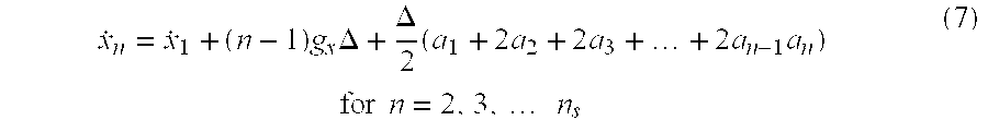
Using the trapezoid rule a second time to integrate equation (6), the following expression is obtained: 
Equations (7) and (8) lead to: 
Equation (9) shows the explicit functional dependence of the displacement on the unknown initial velocity {dot over (x)}1 and gravitational acceleration gx.
FIG. 4 illustrates a method for estimating a lower bound on displacements of the logging tool 18 given that {dot over (x)}1 and gx are unknown. The method starts by acquiring ns acceleration samples during a measurement interval of the logging tool 18 (shown at 46). The next step is to determine the particular values of {dot over ({circumflex over (x)})}1 and ĝx that minimize the estimated tool displacement in the following sense: 
The notation “argp min f(p)” denotes the value of the parameter p that minimizes the expression f(p). The gravitational acceleration ĝx({dot over (x)}1) is estimated by minimizing the sum of squares of the displacement time-series. This value is readily calculated by setting the derivative of the sum of squares with respect to gx to zero: 
The minimization in equation (11) with respect to the initial velocity {dot over (x)}1 is done by searching for the minimum through a set of user-supplied initial velocities {{dot over (x)}1 (1), . . . , {dot over (x)}1 (m)}. An ith initial velocity from the set of user-supplied initial velocities is first obtained (shown at 50). For each ith initial velocity, an estimate ĝx (i) is next calculated using equation (12) above (shown at 52). For each ith initial velocity, there will be a time-series of ns displacements corresponding to the ns acceleration samples and an estimated value of the gravitational acceleration. In step 54, the maximum of the ns-long displacement time-series is selected. The steps 46-54 are repeated until all the displacements for the set of user-supplied initial velocities have been computed. In step 56, the minimum of the maximum displacements computed in step 54 is selected as the lower bound for the displacement of the logging tool 18 during data acquisition. The initial velocity corresponding to this lower bound is the solution to equation (11). The lower bound for the displacement of the logging tool 18 can be used to assess the measurements made by the logging tool 18. For example, the condition that the lower bound for the peak displacement of the logging tool 18 exceeds a certain fraction of the thickness of the resonance volume 42 can be used to flag the NMR measurement as invalid (shown at 57).
In an alternate embodiment, gx is assumed to be approximately constant during the data acquisition period. In this case, the mean value of the acceleration samples acquired in step 45 may provide another estimate of ĝx. This mean value ĝx,mean may replace the estimate ĝx({dot over (x)}1) calculated in step 52.
FIG. 5 illustrates an alternative method for estimating a lower bound for the displacement of the logging tool 18. Because the tool displacement is known up to an arbitrary quadratic polynomial of time, if any quadratic polynomial of time from the displacement time-series is subtracted, the result will also be a displacement time-series that is consistent with the measured acceleration time-series. There is a unique quadratic polynomial that will minimize the sum of squares of the resulting time-series. This is the well-defined, unique lower bound for the tool displacement in the least-squares sense. In this method, the motion of the logging tool 18 is represented by the following expression: 
where {umlaut over (x)}(t) is the acceleration of the logging tool 18 along any one of the tool axes, denoted by x, at time t. The derivative 
is then replaced by a central-difference approximation, as shown in equation (14) below: 
where Δ is the time spacing between xn+1 and xn. For n=1 to ns, where ns is the number of acceleration samples acquired along any one of the tool axes with sample spacing Δ, a system of ns equations can be written using equation (14) above. The system of equations can be expressed in matrix form as follows: 
where 
When equation (5) is substituted into equation (15), the following expression is obtained: 
In this notation, time-series are represented by column vectors. The solution to the matrix equation (16) above is a tool displacement vector x={x1, x2, . . . , xn s }, where x0 and xn s +1 are the boundary values of the displacements of the logging tool 18.
In the following discussion, it is convenient to use Dirac's notation for ket and bra (see Merzbacher, E., Quantum Mechanics, John Wiley & Sons, 1961). Let |x> represent the displacement vector and let |a> represent the vector on the right-hand side of equation (16). Then equation (16) can be rewritten as follows:
The solution to equation (17) is obtained by inverting the matrix T and multiplying the vector |a> by the inverted matrix T:
As shown in equation (15), the matrix T is in tridiagonal form and can be readily inverted. See, for example, Ralston, A. and Wilf, H. S., Editors, Mathematical Methods for Digital Computers, Vol. 2, John Wiley & Sons, 1967. It should be noted that the acceleration data provides the values for the elements of the vector |a>. The boundary conditions x0=xn s +1=0 are used in computing the vector |a>. The result does not depend on the choice of the boundary conditions as the operation of subtracting a quadratic polynomial of time undoes the effect of the boundary values.
The method illustrated in FIG. 5 starts by acquiring ns acceleration samples during a measurement interval of the. logging tool 18 (shown at 58). The next step (shown at 60) involves solving for the displacement vector |x> using equation (18). The method estimates the displacements of the logging tool 18 by removing the projections of |x> onto orthogonal vectors that represent constant, linear, and quadratic time dependencies from |x>. Consider a subspace consisting of three linearly independent vectors |u0>, |u1>, and |u2> in an ns-dimensional vector space, where: 
These vectors are the samples of elementary polynomials, e.g., 1, t, t2 which are linearly independent. Their linear combinations span samples of any quadratic polynomial of time. Orthonomal vectors can be constructed from the vectors |u0>, and |u1>, |u2> by the Gramm-Schmitt orthogonalization procedure:


The linear and quadratic time dependencies are removed from the displacement vector |x> computed in step 60 by subtracting the projection of the displacement vector |x> along the orthogonal vectors |{overscore (u)}1> and |{overscore (u)}1> in equations (20b) and (20c), shown at 62. That is, 
where w=|x>.
The minimum displacements during the data acquisition period are obtained by subtracting the initial position from each element in the displacement vector (shown at 64). That is,
where {circumflex over (x)}1 is the first entry in |{circumflex over (x)}>. The operation in step 62 is equivalent to removing the constant dependencies from the displacement vector. The norms of the vectors |u1> are needed in equations (21) and (22) and can be computed by straightforward algebra using well known summation formulae. See, for example, Jolley, L. B. W., Summation of Series, Dover Publications, Inc., 1961. The norms of the vectors |u1> are:


The norms shown in equations (23a) through (23c) do not change and can be calculated prior to starting the process of acquiring the acceleration samples and estimating a lower bound on the displacement of the logging tool 18 (shown at 66). As in the previous method, if the lower bound determined in step 64 exceeds a predetermined threshold, a flag can be raised (shown at 68). The algorithm described in FIG. 5 is mathematically equivalent to minimizing the sum of squares of equation (9) with respect to {dot over (x)}1 and gx. The lower bounds computed by the methods described in FIGS. 4 and 5 are comparable.
In operations, the logging tool 18 is moved along the borehole 14 to make measurements. The sonde 22 makes NMR measurements by magnetically tipping the nuclear spins of protons in the formation with pulses of the oscillating magnetic field B1, and then detecting the precession of the tipped particles in the resonance volume 42. The accelerometer 44 measures the acceleration of the logging tool 18 during the NMR measurements. The acceleration signals from the accelerometer 44 may be transmitted to the surface in real time or stored in a memory and later transmitted to the surface. At the surface, the acceleration signals may be amplified and then processed. Using the methods described above, the computer 43 computes the true displacements of the logging tool 18 during data acquisition along the three orthogonal axes of the logging tool 18. These true displacements can then be used to isolate portions of the NMR log that may be distorted by motions of the logging tool 18. For example, for T2 relaxation-time measurements, the true displacements along the radial axis of the logging tool 18 can be used to identify invalid data in the NMR log. For T1 relaxation-time measurements, the true displacements along the axial axis of the logging tool 18 is used to assess the quality of the log. It should be clear that the methods described above are not limited to the specific configuration of the logging tool 18 shown in FIGS. 2 and 3, but can be used to determine true displacements of any logging tool in general, regardless of whether the logging tool is used alone or is included in other assemblies, e.g., a drill string.
While the invention has been described with respect to a limited number of embodiments, those skilled in the art will appreciate that other embodiments can be devised which do not depart from the scope of the invention as disclosed herein. Accordingly, the scope of the invention should be limited only by the attached claims.
Claims (11)
1. A method for determining the displacements of a logging tool during a measurement interval of the logging tool in a borehole, the method comprising:
obtaining a set of accelerometer signals corresponding to accelerations of the logging tool along each of three orthogonal axes of the logging tool during the measurement interval;
double integrating the set of accelerometer signals to obtain corresponding displacements of the logging tool as a function of the initial velocity of the logging tool and the gravitational acceleration, wherein the initial velocity of the logging tool and the gravitational acceleration are unknown;
assuming a set of feasible initial velocities for the logging tool;
for each feasible initial velocity, estimating the gravitational acceleration, calculating the displacements of the logging tool using the feasible initial velocity and the estimated gravitational acceleration, and determining the maximum of the calculated displacements; and
setting a lower bound on the displacements of the logging tool to the minimum of the maximum of the calculated displacements.
2. The method of claim 1 , wherein estimating the gravitational acceleration comprises minimizing the sum of the square of the displacements with respect to the unknown gravitational acceleration.
3. The method of claim 1 , wherein estimating the gravitational acceleration includes averaging the accelerometer signals.
4. A method for improving the quality of measurements made by a logging tool during a measurement interval in a borehole, the method comprising:
obtaining a set of accelerometer signals corresponding to accelerations of the logging tool along each of three orthogonal axes of the logging tool during the measurement interval;
double integrating the set of accelerometer signals to obtain corresponding displacements of the logging tool as a function of the initial velocity of the logging tool and the gravitational acceleration, wherein the initial velocity of the logging tool and the gravitational acceleration are unknown;
assuming a set of feasible initial velocities for the logging tool;
for each feasible initial velocity, estimating the gravitational acceleration, calculating the displacements of the logging tool using the feasible initial velocity and the estimated gravitational acceleration, and determining the maximum of the calculated displacements;
estimating a lower bound for the displacements of the logging tool by selecting the minimum of the maximum displacements; and
raising a flag if the lower bound for the displacements of the logging tool exceeds a selected threshold.
5. A method for logging a well, comprising:
moving a logging tool along a borehole to make measurements in a formation surrounding the borehole;
recording the measurements made by the logging tool;
measuring accelerations of the logging tool along each of three orthogonal axes of the logging tool during the measurement interval;
double integrating the set of accelerometer signals to obtain corresponding displacements of the logging tool as a function of the initial velocity of the logging tool and the gravitational acceleration, wherein the initial velocity of the logging tool and the gravitational acceleration are unknown;
assuming a set of feasible initial velocities for the logging tool;
for each feasible initial velocity, estimating the gravitational acceleration, calculating the displacements of the logging tool using the feasible initial velocity and the estimated gravitational acceleration, and determining the maximum of the calculated displacements;
estimating a lower bound for the displacements of the logging tool by selecting the minimum of the maximum displacements; and
raising a flag if the lower bound for the displacements of the logging tool exceeds a selected threshold.
6. A method for determining displacements of a logging tool during a measurement interval of the logging tool in a borehole, the method comprising:
obtaining a set of accelerometer signals corresponding to accelerations of the logging tool along each of three orthogonal axes of the logging tool during the measurement interval;
calculating a tool displacement as a time-series from the accelerometer signals;
constructing a unique quadratic polynomial of time from the displacement time-series; and
subtracting the unique quadratic polynomial from the displacement time-series; and
setting the lower bound to the maximum of the remainder of the displacement time-series.
7. The method of claim 6 , wherein calculating a tool displacement as a time-series from the accelerometer signals includes setting the second time-derivative of the position of the logging tool to the acceleration of the logging tool.
8. The method of claim 7 , further comprising replacing the second time-derivative of the position of the logging tool with a central-difference approximation.
9. The method of claim 8 , further comprising constructing a system of equations from the central-difference approximation and the acceleration of the logging tool and solving the system of equations to obtain the tool displacement.
10. The method of claim 7 , wherein constructing a unique quadratic polynomial of time from the displacement-time series comprises combining elementary polynomials.
11. A method for improving the quality of measurements made by a logging tool during a measurement interval in a borehole, the method comprising:
obtaining a set of accelerometer signals corresponding to accelerations of the logging tool along each of three orthogonal axes of the logging tool during the measurement interval;
calculating a tool displacement as a time-series from the accelerometer signals;
constructing a unique quadratic polynomial of time from the displacement time-series;
subtracting the unique quadratic polynomial from the displacement time-series; and
setting the lower bound to the maximum of the remainder of the displacement time-series; and
raising a flag if the lower bound for the displacements of the logging tool exceeds a selected threshold.
Priority Applications (5)
| Application Number | Priority Date | Filing Date | Title |
|---|---|---|---|
| US09/598,629 US6459992B1 (en) | 1999-07-12 | 2000-06-21 | Method and apparatus for determining logging tool displacements |
| GB0116537A GB2361773B (en) | 1999-07-12 | 2000-06-30 | Method and apparatus for determining logging tool displacements |
| GB0015942A GB2352818B (en) | 1999-07-12 | 2000-06-30 | Method and apparatus for determining logging tool displacements |
| CA002313282A CA2313282C (en) | 1999-07-12 | 2000-06-30 | Method and apparatus for determining logging tool displacements |
| NO20003562A NO329427B1 (en) | 1999-07-12 | 2000-07-11 | Methods for Determining Logging Tool Offsets |
Applications Claiming Priority (2)
| Application Number | Priority Date | Filing Date | Title |
|---|---|---|---|
| US14339399P | 1999-07-12 | 1999-07-12 | |
| US09/598,629 US6459992B1 (en) | 1999-07-12 | 2000-06-21 | Method and apparatus for determining logging tool displacements |
Publications (1)
| Publication Number | Publication Date |
|---|---|
| US6459992B1 true US6459992B1 (en) | 2002-10-01 |
Family
ID=26840992
Family Applications (1)
| Application Number | Title | Priority Date | Filing Date |
|---|---|---|---|
| US09/598,629 Expired - Lifetime US6459992B1 (en) | 1999-07-12 | 2000-06-21 | Method and apparatus for determining logging tool displacements |
Country Status (4)
| Country | Link |
|---|---|
| US (1) | US6459992B1 (en) |
| CA (1) | CA2313282C (en) |
| GB (1) | GB2352818B (en) |
| NO (1) | NO329427B1 (en) |
Cited By (20)
| Publication number | Priority date | Publication date | Assignee | Title |
|---|---|---|---|---|
| US20020077568A1 (en) * | 2000-11-22 | 2002-06-20 | Haddock Thomas F. | Biological vessel volume measurement method and apparatus utilizing micro accelerometer |
| US20030128032A1 (en) * | 2001-12-18 | 2003-07-10 | Heaton Nicholas J. | Method for determining molecular properties of hydrocarbon mixtures from NMR data |
| US20030210043A1 (en) * | 2002-05-10 | 2003-11-13 | Robert Freedman | Processing NMR data in the presence of ringing |
| US6651496B2 (en) | 2001-09-04 | 2003-11-25 | Scientific Drilling International | Inertially-stabilized magnetometer measuring apparatus for use in a borehole rotary environment |
| US20040027122A1 (en) * | 2002-08-12 | 2004-02-12 | Heaton Nicholas J. | Method for detecting hydrocarbons by comparing nmr response at different depths of investigation |
| US20040041562A1 (en) * | 2002-08-28 | 2004-03-04 | Peter Speier | Method for magnetic resonance fluid characterization |
| US20040046552A1 (en) * | 2002-09-06 | 2004-03-11 | Reza Taherian | High vertical resolution antennas for NMR logging |
| US20040169511A1 (en) * | 2003-02-27 | 2004-09-02 | Schlumberger Technology Corporation | [Interpretation Methods for NMR Diffusion-T2 maps] |
| US20050040822A1 (en) * | 2003-01-14 | 2005-02-24 | Heaton Nicholas J. | Multi-measurement NMR analysis based on maximum entropy |
| US7463027B2 (en) * | 2003-05-02 | 2008-12-09 | Halliburton Energy Services, Inc. | Systems and methods for deep-looking NMR logging |
| US20090126486A1 (en) * | 2007-11-20 | 2009-05-21 | Baker Hughes Incorporated | Orientation independent gravity sensor |
| US20100108380A1 (en) * | 2008-11-03 | 2010-05-06 | Baker Hughes Incorporated | Methods and apparatuses for estimating drill bit cutting effectiveness |
| US20100212961A1 (en) * | 2009-02-24 | 2010-08-26 | Baker Hughes Incorporated | Methods and apparatuses for estimating drill bit condition |
| US20100326652A1 (en) * | 2008-06-16 | 2010-12-30 | Halliburton Energy Services, Inc. | Work String Controller |
| US20140222336A1 (en) * | 2013-02-07 | 2014-08-07 | Thomas Frizlen | Method and system for determining displacement of an anchor |
| CN106321074A (en) * | 2016-10-18 | 2017-01-11 | 海斯比得(武汉)石油科技有限公司 | Drilling inclinometer based on optical engine and measurement device of drilling inclinometer |
| WO2017061988A1 (en) * | 2015-10-06 | 2017-04-13 | Halliburton Energy Services, Inc. | Systems and methods for detecting downhole tool location inside a borehole |
| US20180003028A1 (en) * | 2016-06-29 | 2018-01-04 | New Mexico Tech Research Foundation | Downhole measurement system |
| RU2668654C1 (en) * | 2017-08-24 | 2018-10-02 | Федеральное государственное бюджетное учреждение науки Институт геофизики им. Ю.П. Булашевича Уральского отделения Российской академии наук (ИГФ УрО РАН) | Device for measuring geoacoustic signals in well |
| US10625824B2 (en) | 2018-01-13 | 2020-04-21 | Thomas Frizlen | Method and system for determining displacement of an anchor |
Families Citing this family (2)
| Publication number | Priority date | Publication date | Assignee | Title |
|---|---|---|---|---|
| US6518756B1 (en) * | 2001-06-14 | 2003-02-11 | Halliburton Energy Services, Inc. | Systems and methods for determining motion tool parameters in borehole logging |
| US6769497B2 (en) * | 2001-06-14 | 2004-08-03 | Baker Hughes Incorporated | Use of axial accelerometer for estimation of instantaneous ROP downhole for LWD and wireline applications |
Citations (4)
| Publication number | Priority date | Publication date | Assignee | Title |
|---|---|---|---|---|
| US5331578A (en) | 1990-09-14 | 1994-07-19 | Deutsche Forschungsanstalt Fur Luft- Und Raumfahrt E.V. | Procedure for measuring angles and trajectories by means of gyros and inertial systems |
| US5541587A (en) | 1995-01-19 | 1996-07-30 | Western Atlas International, Inc. | System for determining the true depth of an electrical logging tool within a wellbore |
| US6051973A (en) | 1996-12-30 | 2000-04-18 | Numar Corporation | Method for formation evaluation while drilling |
| US6268726B1 (en) * | 1998-01-16 | 2001-07-31 | Numar Corporation | Method and apparatus for nuclear magnetic resonance measuring while drilling |
-
2000
- 2000-06-21 US US09/598,629 patent/US6459992B1/en not_active Expired - Lifetime
- 2000-06-30 CA CA002313282A patent/CA2313282C/en not_active Expired - Fee Related
- 2000-06-30 GB GB0015942A patent/GB2352818B/en not_active Expired - Fee Related
- 2000-07-11 NO NO20003562A patent/NO329427B1/en not_active IP Right Cessation
Patent Citations (4)
| Publication number | Priority date | Publication date | Assignee | Title |
|---|---|---|---|---|
| US5331578A (en) | 1990-09-14 | 1994-07-19 | Deutsche Forschungsanstalt Fur Luft- Und Raumfahrt E.V. | Procedure for measuring angles and trajectories by means of gyros and inertial systems |
| US5541587A (en) | 1995-01-19 | 1996-07-30 | Western Atlas International, Inc. | System for determining the true depth of an electrical logging tool within a wellbore |
| US6051973A (en) | 1996-12-30 | 2000-04-18 | Numar Corporation | Method for formation evaluation while drilling |
| US6268726B1 (en) * | 1998-01-16 | 2001-07-31 | Numar Corporation | Method and apparatus for nuclear magnetic resonance measuring while drilling |
Non-Patent Citations (4)
| Title |
|---|
| A. Ralston & H.S. Wilf, Eds., Mathematical Methods for Digital Computers, vol. 2, p. 233, John Wiley & Sons, Inc., NY (1967). |
| E. Merzbacher, Ed., Quantum Mechanics, Ch. 14, pp. 306-308, John Wiley & Sons, Inc., NY (1961). |
| Francis W. Sears, University Physics, 1987, Addison-Wesley Publishing Company, Seventh Edition, p. 35.* * |
| L.B.W. Jolley, Ed., Summations of Series, 2nd Ed., pp. 4-5, Dover Publications Inc., NY (1961). |
Cited By (37)
| Publication number | Priority date | Publication date | Assignee | Title |
|---|---|---|---|---|
| US20020077568A1 (en) * | 2000-11-22 | 2002-06-20 | Haddock Thomas F. | Biological vessel volume measurement method and apparatus utilizing micro accelerometer |
| US6651496B2 (en) | 2001-09-04 | 2003-11-25 | Scientific Drilling International | Inertially-stabilized magnetometer measuring apparatus for use in a borehole rotary environment |
| US20030128032A1 (en) * | 2001-12-18 | 2003-07-10 | Heaton Nicholas J. | Method for determining molecular properties of hydrocarbon mixtures from NMR data |
| US6838875B2 (en) | 2002-05-10 | 2005-01-04 | Schlumberger Technology Corporation | Processing NMR data in the presence of coherent ringing |
| US20030210043A1 (en) * | 2002-05-10 | 2003-11-13 | Robert Freedman | Processing NMR data in the presence of ringing |
| US20040027122A1 (en) * | 2002-08-12 | 2004-02-12 | Heaton Nicholas J. | Method for detecting hydrocarbons by comparing nmr response at different depths of investigation |
| US6703832B2 (en) | 2002-08-12 | 2004-03-09 | Schlumberger Technology Corporation | Method for detecting hydrocarbons by comparing NMR response at different depths of investigation |
| US20040041562A1 (en) * | 2002-08-28 | 2004-03-04 | Peter Speier | Method for magnetic resonance fluid characterization |
| US6859033B2 (en) | 2002-08-28 | 2005-02-22 | Schlumberger Technology Corporation | Method for magnetic resonance fluid characterization |
| US6781371B2 (en) | 2002-09-06 | 2004-08-24 | Schlumberger Technology Corporation | High vertical resolution antennas for NMR logging |
| US20040046552A1 (en) * | 2002-09-06 | 2004-03-11 | Reza Taherian | High vertical resolution antennas for NMR logging |
| US20050040822A1 (en) * | 2003-01-14 | 2005-02-24 | Heaton Nicholas J. | Multi-measurement NMR analysis based on maximum entropy |
| US6960913B2 (en) | 2003-01-14 | 2005-11-01 | Schlumberger Technology Corporation | Multi-measurement NMR analysis based on maximum entropy |
| US20040169511A1 (en) * | 2003-02-27 | 2004-09-02 | Schlumberger Technology Corporation | [Interpretation Methods for NMR Diffusion-T2 maps] |
| US7034528B2 (en) | 2003-02-27 | 2006-04-25 | Schlumberger Technology Corporation | Methods for formation evaluation based on multi-dimensional representation of nuclear magnetic resonance data |
| US20060122779A1 (en) * | 2003-02-27 | 2006-06-08 | Schlumberger Technology Corporation | Interpretation methods for NMR diffusion-T2 maps |
| US7388374B2 (en) | 2003-02-27 | 2008-06-17 | Schlumberger Technology Corporation | Interpretation methods for NMR diffusion-T2 maps |
| US7463027B2 (en) * | 2003-05-02 | 2008-12-09 | Halliburton Energy Services, Inc. | Systems and methods for deep-looking NMR logging |
| US20090126486A1 (en) * | 2007-11-20 | 2009-05-21 | Baker Hughes Incorporated | Orientation independent gravity sensor |
| WO2009088567A1 (en) * | 2007-11-20 | 2009-07-16 | Baker Hughes Incorporated | Orientation independent gravity sensor |
| US20100326652A1 (en) * | 2008-06-16 | 2010-12-30 | Halliburton Energy Services, Inc. | Work String Controller |
| US20100326653A1 (en) * | 2008-06-16 | 2010-12-30 | Halliburton Energy Services, Inc. | Work String Controller |
| US7866403B1 (en) | 2008-06-16 | 2011-01-11 | Halliburton Energy Services Inc. | Work string controller |
| US7971638B2 (en) * | 2008-06-16 | 2011-07-05 | Halliburton Energy Services Inc. | Work string controller |
| US8016050B2 (en) * | 2008-11-03 | 2011-09-13 | Baker Hughes Incorporated | Methods and apparatuses for estimating drill bit cutting effectiveness |
| US20100108380A1 (en) * | 2008-11-03 | 2010-05-06 | Baker Hughes Incorporated | Methods and apparatuses for estimating drill bit cutting effectiveness |
| US8028764B2 (en) * | 2009-02-24 | 2011-10-04 | Baker Hughes Incorporated | Methods and apparatuses for estimating drill bit condition |
| US20100212961A1 (en) * | 2009-02-24 | 2010-08-26 | Baker Hughes Incorporated | Methods and apparatuses for estimating drill bit condition |
| US20140222336A1 (en) * | 2013-02-07 | 2014-08-07 | Thomas Frizlen | Method and system for determining displacement of an anchor |
| US9250082B2 (en) * | 2013-02-07 | 2016-02-02 | Thomas Frizlen | Method and system for determining displacement of an anchor |
| WO2017061988A1 (en) * | 2015-10-06 | 2017-04-13 | Halliburton Energy Services, Inc. | Systems and methods for detecting downhole tool location inside a borehole |
| EP3356645A4 (en) * | 2015-10-06 | 2019-05-29 | Halliburton Energy Services, Inc. | Systems and methods for detecting downhole tool location inside a borehole |
| US20180003028A1 (en) * | 2016-06-29 | 2018-01-04 | New Mexico Tech Research Foundation | Downhole measurement system |
| CN106321074A (en) * | 2016-10-18 | 2017-01-11 | 海斯比得(武汉)石油科技有限公司 | Drilling inclinometer based on optical engine and measurement device of drilling inclinometer |
| CN106321074B (en) * | 2016-10-18 | 2023-10-24 | 海斯比得(武汉)石油科技有限公司 | Optical engine-based inclinometer while drilling and measuring device thereof |
| RU2668654C1 (en) * | 2017-08-24 | 2018-10-02 | Федеральное государственное бюджетное учреждение науки Институт геофизики им. Ю.П. Булашевича Уральского отделения Российской академии наук (ИГФ УрО РАН) | Device for measuring geoacoustic signals in well |
| US10625824B2 (en) | 2018-01-13 | 2020-04-21 | Thomas Frizlen | Method and system for determining displacement of an anchor |
Also Published As
| Publication number | Publication date |
|---|---|
| GB2352818B (en) | 2001-09-26 |
| CA2313282A1 (en) | 2001-01-12 |
| CA2313282C (en) | 2006-06-06 |
| GB2352818A (en) | 2001-02-07 |
| NO20003562L (en) | 2001-01-15 |
| GB0015942D0 (en) | 2000-08-23 |
| NO20003562D0 (en) | 2000-07-11 |
| NO329427B1 (en) | 2010-10-18 |
Similar Documents
| Publication | Publication Date | Title |
|---|---|---|
| US6459992B1 (en) | Method and apparatus for determining logging tool displacements | |
| US20190271224A1 (en) | Correction of motion effect in nuclear magnetic resonance (nmr) logging | |
| US7196516B2 (en) | Correction of NMR artifacts due to constant-velocity axial motion and spin-lattice relaxation | |
| EP1405107B1 (en) | Fast t1 measurement of a geologic formation | |
| US8022698B2 (en) | Joint compression of multiple echo trains using principal component analysis and independent component analysis | |
| CA2010398C (en) | Method to improve directional survey accuracy | |
| EP3423675B1 (en) | Motion detection and correction of magnetic resonance data | |
| US20130214779A1 (en) | Method and system to characterize a property of an earth formation | |
| US10024997B2 (en) | Determining the Larmor frequency for NMR tools | |
| US20140033815A1 (en) | Relaxivity-insensitive measurement of formation permeability | |
| US10302801B2 (en) | Temperature correction of magnetic resonance data | |
| US8912916B2 (en) | Non-uniform echo train decimation | |
| US6437564B1 (en) | Estimate of transversal motion of the NMR tool during logging | |
| US20130181707A1 (en) | System and method to detect a fluid flow | |
| US11435496B2 (en) | Reducing data bandwidth requirements in downhole nuclear magnetic resonance processing | |
| GB2361773A (en) | Determining logging tool displacements | |
| US20220365242A1 (en) | Correction of nuclear magnetic resonance data in high vibration environments | |
| US11428842B2 (en) | Speed of tool assessment via speed kernels | |
| US20230068555A1 (en) | Correction of distorted gradient distributions in nuclear magnetic resonance logging |
Legal Events
| Date | Code | Title | Description |
|---|---|---|---|
| STCF | Information on status: patent grant |
Free format text: PATENTED CASE |
|
| FPAY | Fee payment |
Year of fee payment: 4 |
|
| FPAY | Fee payment |
Year of fee payment: 8 |
|
| FPAY | Fee payment |
Year of fee payment: 12 |