US6464464B2 - Apparatus and method for controlling a pump system - Google Patents
Apparatus and method for controlling a pump system Download PDFInfo
- Publication number
- US6464464B2 US6464464B2 US09/275,498 US27549899A US6464464B2 US 6464464 B2 US6464464 B2 US 6464464B2 US 27549899 A US27549899 A US 27549899A US 6464464 B2 US6464464 B2 US 6464464B2
- Authority
- US
- United States
- Prior art keywords
- pump
- control signal
- alarm
- flow
- speed
- Prior art date
- Legal status (The legal status is an assumption and is not a legal conclusion. Google has not performed a legal analysis and makes no representation as to the accuracy of the status listed.)
- Expired - Lifetime
Links
Images


Classifications
-
- F—MECHANICAL ENGINEERING; LIGHTING; HEATING; WEAPONS; BLASTING
- F04—POSITIVE - DISPLACEMENT MACHINES FOR LIQUIDS; PUMPS FOR LIQUIDS OR ELASTIC FLUIDS
- F04D—NON-POSITIVE-DISPLACEMENT PUMPS
- F04D15/00—Control, e.g. regulation, of pumps, pumping installations or systems
-
- F—MECHANICAL ENGINEERING; LIGHTING; HEATING; WEAPONS; BLASTING
- F04—POSITIVE - DISPLACEMENT MACHINES FOR LIQUIDS; PUMPS FOR LIQUIDS OR ELASTIC FLUIDS
- F04D—NON-POSITIVE-DISPLACEMENT PUMPS
- F04D15/00—Control, e.g. regulation, of pumps, pumping installations or systems
- F04D15/0066—Control, e.g. regulation, of pumps, pumping installations or systems by changing the speed, e.g. of the driving engine
Definitions
- This invention relates generally to control systems, and more particularly to a controller for controlling flow, speed, pressure or performance of a pumping system.
- a typical centrifugal pump of the prior art comprises an impeller, rotatably mounted in a stationary casing with the rotating impeller imparting pressure and kinetic energy to the fluid being pumped, and the stationary casing guiding the fluid to and from the impeller.
- a typical centrifugal pump casing which generally includes concentric, diffusor and volute type centrifugal casings
- the rotation of the impeller imparts kinetic energy to the fluid and causes fluid flow, in a generally circular direction about the perimeter of the impeller, through the casing surrounding the impeller.
- the fluid flows from the perimeter of the impeller, passes a cut-water or the like through an area of the pump generally known as the discharge inlet area and through the discharge nozzle to the pump discharge.
- variable frequency devices have been used to adjust the motor speed of the pump so as to regulate the flow within the pump system.
- variable frequency drives are to include adjustable frequency drives (AFDs), Variable Speed Controllers (VSCs) or something similar, which operate to control electronic motor speed.
- VFD variable frequency device
- the controller comprises a storage device for storing data indicative of at least one operating condition and a microprocessor in communication with the sensor and operative to perform an algorithm utilizing the at least one sensor signal and the stored data indicative of the at least one operating condition to generate a control signal, wherein the control signal is indicative of a correction factor to be applied to the pump.
- a method for automatically controlling operating parameters associated with a centrifugal pump according to an algorithm for pumping fluid to a discharge outlet comprising the steps of storing in memory data values corresponding to predetermined operating conditions, obtaining sensor measurements indicative of current operating conditions, utilizing the sensor measurements and the stored data values to determine calculated data values corresponding to the current pump operating conditions, and comparing the calculated data values with the stored data values and generating a control signal indicative of a correction factor to be applied to the pump when the calculated data values differ from the stored data values by a predetermined amount.
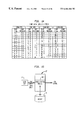
- FIG. 1 is a block diagram of the pumping system and controller according to the present invention.
- FIG. 2 is a block diagram illustrating the microprocessor and storage associated with the controller for controlling the pumping system according to the present invention.
- FIG. 3A is a functional block diagram of the program controller modules operative for controlling the pumping system according to the present invention.
- FIG. 3B is an exemplary illustration of the pump data required for the program calculations of the controller.
- FIG. 3C is an illustration of the site specific data required for the calculations required for the controller.
- FIG. 3D is a more detailed block diagram of FIG. 3A illustrating the major functional components associated with the controller according to the present invention.
- FIG. 4A is a block diagram illustrating the inputs and outputs for determining the capacity of the pumping system.
- FIG. 4B represents a flow chart depicting the steps involved in obtaining the flow calculation associated with the controller according to the present invention.
- FIG. 5A is a flow chart depicting the TDH logic module associated with the controller.
- FIG. 5B is a flow chart depicting the NPSH logic module associated with the controller.
- FIG. 6 is a flow chart depicting the capacity logic module associated with the controller.
- FIG. 7 is a flow chart depicting the pressure logic module associated with the controller.
- FIG. 8 is a flow chart depicting the low flow logic module associated with the controller.
- FIG. 9 is a flow chart depicting the wire-to-water efficiency logic flow module associated with the controller.
- FIG. 10 represents a data table of stored information comprising data values of water specific gravity v. temperature.
- FIG. 11 represents a data table of stored information comprising water vapor pressure v. pressure data.
- FIG. 12 represents a data table of stored information comprising pump pressure v. flow data at four different pump speeds.
- FIG. 13 represents a data table of stored information comprising pump performance data at four different pump speeds.
- FIG. 14 represents a data table of stored information comprising pump NPSHr data at four different pump speeds.
- FIG. 15 is a block diagram depicting the functioning of the variable speed control module associated with the controller.
- FIG. 16 is a detailed block diagram depicting the major functional software programs associated with the controller coupled to separate alarm monitor devices according to the present invention.
- a controller 10 coupled to a pumping system 20 comprising a motor 30 operative for powering centrifugal pump 40 .
- a centrifugal pump is depicted in U.S. Pat. No. 5,129,264 entitled CENTRIFUGAL PUMP WITH FLOW MEASUREMENT, issued Jul. 14, 1992 and incorporated herein by reference. Note that when referring to the drawings, like reference numerals are used to indicate like parts.
- the controller, or variable/adjustable frequency device (VFD) 10 operates to control flow, speed or pressure of the pumping system by monitoring motor, pump and system parameters and controlling pump output via speed variation and identifying and reporting pump system problems.
- novel controller may be embedded within the VFD or may be externally connected between a VFD and the pumping system. More particularly, as will be described in more detail, the microprocessor containing the executable software code for controlling the motor speed may reside physically within the VFD or external to the VFD. The latter implementation permits control for use with virtually any type of VFD devices.
- sensors 1 - 6 are coupled to the pumping system 20 and are operative for sensing various operating conditions associated with the pump and inputting these values to controller 10 via communication line 22 .
- FIG. 2 shows a more detailed illustration of the controller 10 connected to the pump system 20 .
- the controller comprises a processor 12 such as a microprocessor operative to perform software functions which utilize the sensor signals or sensor data obtained from each of the pump sensors to determine the pump operating conditions.
- the microprocessor 12 may be a large scale integrated (LSI) or VLSI integrated circuit controlled by software programs allowing operation of arithmetic calculations, logic and I/O operations.
- Other processors, including digital signal processors (DSPs) are also contemplated.
- Memory storage device or data base 14 such as a random access memory, (RAM) or other addressable memory is included within the controller for storing data values and tables associated with pump operating conditions and parameters.
- the microprocessor controller 12 receives the sensor signal data and processes the input data along with stored table data in memory 14 .
- the microprocessor performs this processing by activating software programs which respond to the sensor inputs, as well as to pre-stored data parameters to perform a myriad of arithmetic calculations for comparison with threshold values.
- the software programs may be resident in microprocessor memory locations.
- the software functions to generate an alarm signal indicative of an alarm condition associated with a particular operating parameter(s), and/or generates a signal for input to the pumping system to alter the current motor speed to correct for an abnonnal operating condition when the difference between the calculated and stored parameter values exceed a predetermined numeric value.
- the controller operates to generate a control signal to VFD logic within the VFD/controller 10 indicative of a request to reduce or increase motor speed in order to correct for detected abnormal condition.
- the VFD then generates a signal to the motor 30 corresponding to a change in voltage and/or frequency to cause the speed of the motor to change in an amount proportional to the controller generated control signal.
- the controller may also operate to generate a second output control signal 19 to an alarm monitor 23 indicative of a detected abnormality in order to alert a technician of the detected condition so as to allow him to investigate and/or adjust certain parameters associated with the operating conditions.
- a plurality of sensor inputs from each of the sensors 1 - 6 are provided to the controller. These inputs include absolute pump suction pressure P s (ref. numeral 1 ), absolute pump discharge pressure P d (ref. numeral 2 ), differential pressure ⁇ P (ref. numeral 3 ), pump speed Nact (ref. numeral 4 ), pumpage temperature T p (ref. numeral 5 ) and motor power (ref. numeral 6 ).
- pump suction pressure, pump discharge pressure, and the differential pressure are typically measured in feet H 2 O, while the pump speed is in RPMs. Fluid temparature is preferably measured in degrees Fahrenheit, while the units associated with motor power are generally kilowatts (kw).
- the differentail pressure for flow might be direct G.P.M. measured from a flow meter, while pump speed may be from either the controller or via direct measurement. In similar fashion, motor power may also be from the controller or via direct sensor measurement.
- An additional input 7 such as a customer adjustable parameter or set point may also be input into the controller 10 via a user interface (see FIG. 3A) as the parameter which operates to trigger a correction factor or an alarm in response to one of the sensed operating conditions.
- Additional auxiliary sensor inputs 8 may also be utilized by the controller such as additional pressure gauges for measuring barometric pressure.
- each of the sensors are conventional sensor elements such as transducers positioned on or within the pumping system in a well-known manner that act to translate each sensed operating condition into a corresponding electronic signal for input to the controller.
- FIG. 3A illustrates a block diagram of the controller software capabilities.
- the controller includes a plurality of software programs 17 which execute algorithms and perform calculations associated with the monitoring of motor, pump and system parameters and for controlling, identifying and reporting on these parameters.
- the sensor input data from the pump is input to microprocessor 12 and received by a setup program 16 which performs initialization, timing control, scaling of the input data, and receipt and storage via memory 14 of parameter values.
- the controller 10 includes a user interface portion 29 for receiving parameter data directly from a user, such as customer adjustable set points for trigger conditions, manual override for inputting a desired pump speed, or the site specific data (see FIG. 3C) and/or pump data (see FIG.
- the setup program 16 initiates each of the subprograms in module 17 , as will be explained in further detail below.
- the software associated with program 16 is operative to retrieve and display via the user interface 29 pump system parameters, inputted parameters as well as the sensor input and output conditions and calculated values resulting from the algorithmic execution in program module 17 .
- the program also includes code which compares the user entered setting information/parameters with threshold values stored in memory so as to avoid illegal operation settings.
- the software module 17 has program code to perform a number of calculations for determining the pump operating condition, and based on the calculated operating condition, and based on the calculated operating condition in comparison with preset threshold values, the controller will send a control signal 15 to the pump motor 30 to either reduce or increase the motor speed.
- the control signal may have a variety of amplitude values and/or pulse widths indicative of the relative degree of increase or decrease of the motor speed relative to its present speed.
- Software programs 17 may also send a control signal 19 to an alarm indicator 23 to indicate any failure or abnormality in the system which inhibits operation of the pump.
- Storage area 14 comprises storage media for storing site specific data required for software program execution and calculation and includes maximum pump speed, vapor pressure v. temperature, specific gravity v. temperature, capacity set point, and pressure set point and stability factor (cf). Such site specific data requirements for controller calculations are shown in FIG. 3 C. As shown in FIG.
- pump data required for the controller calculations are stored in storage area 14 , such as a database, and include pump discharge diameter, pump suction diameter, suction gauge height to suction CL, net gauge height difference, minimum continuous capacity, minimum allowable capacity, TDH new v. capacity at different speeds, and NPSHR v. capacity at different speeds.
- FIG. 3D shows a more detailed block diagram of the controller software capabilities of program module 17 (FIG. 3A) which generally comprise the following software modules: capacity/flow determination module 171 , TDH performance logic module 173 , NPSH logic 175 , wire-to-water efficiency module 177 , capacity flow control logic 179 , pressure control logic 181 , low flow logic 183 , and variable speed control module 185 .
- the processing associated with each of these modules will be described below.
- each of these algorithmic processes are executed at a frequency of 10 times per second in order to sufficiently monitor and correct for any abnormalities.
- each of the modules utilize in general, both the sensor data and stored parameter data (stored in memory 14 ) obtained from prior calculations to determine the pump operating conditions.
- the modules output control signals to activate either performance alarm 23 and/or to adjust the motor speed of motor 30 .
- FIG. 4A shows a block diagram of the capacity determination module of the controller which receives as input the sensor inputs ⁇ P, T p , and n in order to calculate the capacity of the pump system utilizing the technique disclosed in U.S. Pat. No. 5,129,264. Note also that the capacity Q can be obtained directly from a flow meter, as well as utilizing the above-mentioned technique.
- FIG. 4B represents a flow diagram for obtaining the flow calculation associated with flow determination software module 171 .
- pumpage temperature T p and pump speed n sensor data is received and the specific gravity (S p GR) be selected from the parameter data in the data base comprising water specific gravity versus temperature, as shown in FIG. 10 .
- the software then operates to select from the parameter data illustrated in FIG. 12 of pump ⁇ pressure versus flow at different speeds, the speed value in the data base having a value closest to the sensed pump speed from sensor 4 .
- the differential pressure ( ⁇ P) input via sensor 3 is then used to determine and select the tabulated flow having a value of ⁇ ft. pressure closest to the sensor input ⁇ P value.
- FIG. 5A there is depicted a flow diagram of the pump total dynamic head (TDH) logic portion 173 of the controller 10 which operates to determine the total dynamic head and pump performance.
- TDH pump total dynamic head
- data values associated with pumpage fluid specific gravity are stored in tables (or as equations) in memory 14 , as well as the pump data (see FIG. 3 B). Such a table is illustrated in FIG. 10 .
- the TDH logic controller also processes table data associated with pumpage fluid vapor pressure (FIG. 11) and ⁇ pressure v. flow for up to six speeds as shown in FIG. 12 .
- the flow diagram of FIG. 5A illustrates the following steps of determining the pump total dynamic head and comparing the calculated value with a threshold value. If the actual pump TDH at a given flow is below a preset value (e.g. 85-95% of the table value) then a control signal is output to activate a performance alarm.
- the TDH determination steps are as follows:
- Ds is pump discharge pipe diameter in inches.
- Dd is pump suction pipe diameter in inches.
- Dd and Ds parameters are input data.
- Q is pump flow in GPM from the flow calculation or directly from a Flow meter.
- TDH (Pd ⁇ Ps)/SG+ ⁇ Z+ ⁇ hv
- Pd is the pump discharge pressure (absolute) in ft.
- Ps is the pump suction pressure (absolute) in ft.
- ⁇ Z is net gage height difference input parameter data between Pd & Ps gages in ft.
- ⁇ hv is the Net Velocity Head
- SP GR is pumpage specific gravity
- the pump performance comparison is then performed utilizing the actual pump speed, the flow value and the determined TDH value.
- the pump performance comparison method is identified below as follows:
- NPSH net positive suction head
- inputs to the NPSH module comprise Q capacity, vapor pressure (Pv), specific gravity, pump suction pressure, pumpage temperature and fluid temperature.
- Pv vapor pressure
- specific gravity vapor pressure
- pump suction pressure pumpage temperature
- fluid temperature fluid temperature
- Ds is pump suction pipe diameter input value in inches.
- NPSHa (Ps+Pv)/SG+ ⁇ Zs+hvs
- Ps is pump suction pressure absolute in ft.
- Pv is pumpage vapor pressure in ft.
- SP GR is pumpage specific gravity determined from flow module 171 .
- ⁇ Zs is the difference in suction gage height to pump suction input data in ft.
- hvs is suction velocity head in ft. determined from step c.
- a comparison of the NPSHa versus NPSHr stored in the data base 14 is then made. If the NPSHa is less than the Net Positive Suction Head Required (NPSHr) of the pump, the program outputs a control signal to alarm and/or reduce the pump speed to prevent the pump from continuing to operate in a cavitating condition.
- the following steps depict the NPSHa v. NPSHr comparison steps.
- the calculated results are compared to the tabulated pump performance and NPSHr values, such that in the preferred embodiment, if performance is less than 95% (user selectable), then an alarm is activated. If the NPSHr of the pump is greater than the NPSHa of the system, alarm 23 is activated.
- the controller 10 also includes a software program module 177 which performs a wire to water efficiency analysis. As shown in the flow diagram of FIG. 9, the steps associated with this wire to water efficiency of the pumping system is as follows:
- TDH is pump head in ft. from module 173
- SP GR is pumpage specific gravity
- KW is kilowatt input in kilowatts (kw).
- FIG. 6 illustrates capacity logic portion 179 of the controller 10 .
- the processing for flow control comprises setting the capacity (Q set), determining whether the capacity is within a desired range by comparing the actual capacity Qact to the Qset value, and adjusting the speed by a factor
- Nnew Nold +((((i Qset/Qact)* Nold ) ⁇ Nold )* CF
- Nold is the actual pump speen and CF is stability factor set by customer (typically 0.1 to 1.0). CF is used to prevent overcorrecting and instability in the control of the pump flow and speed as shown in FIG. 6, the output control signal operates to either increase of decrease motor speed to the pump motor.
- FIG. 7 illustrates a process variable control for pressure determination module 181 associated with the controller 10 . As shown in FIG. 7, the steps associated with this variable control comprises:
- CF is a stability factor set by customer (typically 0.1 to 1.0)
- CF is used to prevent overcorrecting and instability in the control of the pump pressure and speed.
- the output control signal of module 181 operates to either increase or decrease the pump motor speed.
- FIG. 8 illustrates a flow diagram of the low flow logic module 183 portion of the controller 10 which compares the operating pump flow to the pump's calculated minimum continuous flow. If the actual flow rate is below the minimum continuous flow, an alarm is activated. The operating pump flow is also compared to the pump's calculated minimum allowable flow, such that if the actual flow rate is below the minimum allowable flow, the software program operates to provide a control signal to activate an alarm and/or reduce pump speed to prevent the pump from continuing to operate below the minimum allowable flow.
- the following steps depict each of the above-identified conditions.
- the variable speed control module 185 operates as depicted in the flow diagram of FIG. 15 . As shown in FIG. 15, the desired pump speed is selected and input to the module via user interface 29 . The selected pump speed input to module 185 via a user is stored in the data base 14 and a control signal is output from the controller to set the desired speed of motor 30 .
- the controller operates to notify and correct pump operating parameters including pump flow, pump performance, pump pressure and speed in order to effectively control and maintain the pump in an efficient and active state.
- each of the software application modules may provide a separate control signal which may be directed to a separate respective alarm monitor including an LED or a buzzer which would alert the technician to the precise overflow or overload condition.
- a separate respective alarm monitor including an LED or a buzzer which would alert the technician to the precise overflow or overload condition.
- Such a set of alarm monitors respectively coupled to the software modules is illustrated in FIG. 16 .
- the alarm monitors may be connected to a separate computing system or computer network which may operate to alert an individual at a location remote from the location of the pump.
- the application program code associated with the setup program 16 and 17 may be written in a variety of higher level languages such as basic, C, or other high level languages and operates in combination with conventional operating systems in a well known fashion so as to properly communicate with the pump sensors, pump motor, and any peripheral devices.
- the controller may be housed within a VFD for receiving pump sensor data and outputting control signals to adjust the pump motor speed, or may be external to a VFD and located within an interface module and connected to the VFD, such that all input data is sent to the controller via the VFD and a control signal to adjust motor speed is output from the controller to the VFD for adjusting the speed of the electronic pump motor. All such modifications are intended to be included within the scope of the invention as defined in the appended claims.
Abstract
A controller for controlling operating parameters associated with fluid flow, speed or pressure for a centrifugal pump for pumping fluid, wherein at least one sensor is coupled to the pump for generating a signal indicative of a sensed operating condition. The controller comprises a storage device for storing data indicative of at least one operating condition and a processor in communication with the sensor and operative to perform an algorithm utilizing the at least one sensor signal and the stored data indicative of the at least one operating condition to generate a control signal, wherein the control signal includes a correction factor between 0.1 and 1.0 that is applied to the pump controlling algorithm in order to prevent overcorrection.
Description
This invention relates generally to control systems, and more particularly to a controller for controlling flow, speed, pressure or performance of a pumping system.
A typical centrifugal pump of the prior art comprises an impeller, rotatably mounted in a stationary casing with the rotating impeller imparting pressure and kinetic energy to the fluid being pumped, and the stationary casing guiding the fluid to and from the impeller. In a typical centrifugal pump casing, which generally includes concentric, diffusor and volute type centrifugal casings, the rotation of the impeller imparts kinetic energy to the fluid and causes fluid flow, in a generally circular direction about the perimeter of the impeller, through the casing surrounding the impeller. At some point in the casing, the fluid flows from the perimeter of the impeller, passes a cut-water or the like through an area of the pump generally known as the discharge inlet area and through the discharge nozzle to the pump discharge.
The fluid flow can be affected by the design of the impeller, the design and size of the casing, the speed at which the impeller rotates, and design and size of the pump inlet and outlet, quality and finish of the components, presence of a casing volute and the like. In order to control fluid flow, variable frequency devices have been used to adjust the motor speed of the pump so as to regulate the flow within the pump system. It is to be noted that, as used herein, variable frequency drives are to include adjustable frequency drives (AFDs), Variable Speed Controllers (VSCs) or something similar, which operate to control electronic motor speed.
Pump speed and pressure represent important pumping system parameters, in addition to flow, which can cause the pump to operate at less than its most efficient level. Even more disadvantageously, less than optimal operating parameters may cause the pump and motor to work harder and thus wear out quicker, thereby shortening the pump's operational lifetime. According, it is highly desirable to provide a computer-controlled variable frequency device (VFD) controller which utilizes computer algorithms and sensor inputs to control flow, speed, pressure and performance of a pumping system by monitoring motor, pump and system parameters and controlling pump output via speed variations. It is also advantageous to obtain a controller operative to identify and report pump or system anomalies to a technician, to facilitate investigation and correction of any abnormalities before any serious damage to the pumping unit occurs.
A controller for controlling operating parameters associated with fluid flow, speed or pressure for a centrifugal pump for pumping fluid, wherein at least one sensor is coupled to the pump for generating a signal indicative of a sensed operating condition. The controller comprises a storage device for storing data indicative of at least one operating condition and a microprocessor in communication with the sensor and operative to perform an algorithm utilizing the at least one sensor signal and the stored data indicative of the at least one operating condition to generate a control signal, wherein the control signal is indicative of a correction factor to be applied to the pump.
There is also disclosed a method for automatically controlling operating parameters associated with a centrifugal pump according to an algorithm for pumping fluid to a discharge outlet, comprising the steps of storing in memory data values corresponding to predetermined operating conditions, obtaining sensor measurements indicative of current operating conditions, utilizing the sensor measurements and the stored data values to determine calculated data values corresponding to the current pump operating conditions, and comparing the calculated data values with the stored data values and generating a control signal indicative of a correction factor to be applied to the pump when the calculated data values differ from the stored data values by a predetermined amount.
FIG. 1 is a block diagram of the pumping system and controller according to the present invention.
FIG. 2 is a block diagram illustrating the microprocessor and storage associated with the controller for controlling the pumping system according to the present invention.
FIG. 3A is a functional block diagram of the program controller modules operative for controlling the pumping system according to the present invention.
FIG. 3B is an exemplary illustration of the pump data required for the program calculations of the controller.
FIG. 3C is an illustration of the site specific data required for the calculations required for the controller.
FIG. 3D is a more detailed block diagram of FIG. 3A illustrating the major functional components associated with the controller according to the present invention.
FIG. 4A is a block diagram illustrating the inputs and outputs for determining the capacity of the pumping system.
FIG. 4B represents a flow chart depicting the steps involved in obtaining the flow calculation associated with the controller according to the present invention.
FIG. 5A is a flow chart depicting the TDH logic module associated with the controller.
FIG. 5B is a flow chart depicting the NPSH logic module associated with the controller.
FIG. 6 is a flow chart depicting the capacity logic module associated with the controller.
FIG. 7 is a flow chart depicting the pressure logic module associated with the controller.
FIG. 8 is a flow chart depicting the low flow logic module associated with the controller.
FIG. 9 is a flow chart depicting the wire-to-water efficiency logic flow module associated with the controller.
FIG. 10 represents a data table of stored information comprising data values of water specific gravity v. temperature.
FIG. 11 represents a data table of stored information comprising water vapor pressure v. pressure data.
FIG. 12 represents a data table of stored information comprising pump pressure v. flow data at four different pump speeds.
FIG. 13 represents a data table of stored information comprising pump performance data at four different pump speeds.
FIG. 14 represents a data table of stored information comprising pump NPSHr data at four different pump speeds.
FIG. 15 is a block diagram depicting the functioning of the variable speed control module associated with the controller.
FIG. 16 is a detailed block diagram depicting the major functional software programs associated with the controller coupled to separate alarm monitor devices according to the present invention.
Referring now to FIG. 1, there is shown a controller 10 coupled to a pumping system 20 comprising a motor 30 operative for powering centrifugal pump 40. Such a centrifugal pump is depicted in U.S. Pat. No. 5,129,264 entitled CENTRIFUGAL PUMP WITH FLOW MEASUREMENT, issued Jul. 14, 1992 and incorporated herein by reference. Note that when referring to the drawings, like reference numerals are used to indicate like parts. The controller, or variable/adjustable frequency device (VFD) 10, operates to control flow, speed or pressure of the pumping system by monitoring motor, pump and system parameters and controlling pump output via speed variation and identifying and reporting pump system problems. (Note that flow measurements may be obtained using conventional flow measuring devices such as ventures, orifice plates, mag meters and the like, as well as by the technique outlined in U.S. Pat. No. 5,129,264.) Note further that the novel controller according to the present invention may be embedded within the VFD or may be externally connected between a VFD and the pumping system. More particularly, as will be described in more detail, the microprocessor containing the executable software code for controlling the motor speed may reside physically within the VFD or external to the VFD. The latter implementation permits control for use with virtually any type of VFD devices.
As shown in FIG. 1, sensors 1-6 are coupled to the pumping system 20 and are operative for sensing various operating conditions associated with the pump and inputting these values to controller 10 via communication line 22. FIG. 2 shows a more detailed illustration of the controller 10 connected to the pump system 20. The controller comprises a processor 12 such as a microprocessor operative to perform software functions which utilize the sensor signals or sensor data obtained from each of the pump sensors to determine the pump operating conditions. The microprocessor 12 may be a large scale integrated (LSI) or VLSI integrated circuit controlled by software programs allowing operation of arithmetic calculations, logic and I/O operations. Other processors, including digital signal processors (DSPs) are also contemplated. Memory storage device or data base 14 such as a random access memory, (RAM) or other addressable memory is included within the controller for storing data values and tables associated with pump operating conditions and parameters. The microprocessor controller 12 receives the sensor signal data and processes the input data along with stored table data in memory 14. The microprocessor performs this processing by activating software programs which respond to the sensor inputs, as well as to pre-stored data parameters to perform a myriad of arithmetic calculations for comparison with threshold values. The software programs may be resident in microprocessor memory locations. Based on the results of those calculations and the comparison with threshold values, the software functions to generate an alarm signal indicative of an alarm condition associated with a particular operating parameter(s), and/or generates a signal for input to the pumping system to alter the current motor speed to correct for an abnonnal operating condition when the difference between the calculated and stored parameter values exceed a predetermined numeric value. The controller operates to generate a control signal to VFD logic within the VFD/controller 10 indicative of a request to reduce or increase motor speed in order to correct for detected abnormal condition. The VFD then generates a signal to the motor 30 corresponding to a change in voltage and/or frequency to cause the speed of the motor to change in an amount proportional to the controller generated control signal. The controller may also operate to generate a second output control signal 19 to an alarm monitor 23 indicative of a detected abnormality in order to alert a technician of the detected condition so as to allow him to investigate and/or adjust certain parameters associated with the operating conditions.
As shown in FIG. 1, a plurality of sensor inputs from each of the sensors 1-6 are provided to the controller. These inputs include absolute pump suction pressure Ps (ref. numeral 1), absolute pump discharge pressure Pd (ref. numeral 2), differential pressure ΔP (ref. numeral 3), pump speed Nact (ref. numeral 4), pumpage temperature Tp (ref. numeral 5) and motor power (ref. numeral 6). Note that pump suction pressure, pump discharge pressure, and the differential pressure are typically measured in feet H2O, while the pump speed is in RPMs. Fluid temparature is preferably measured in degrees Fahrenheit, while the units associated with motor power are generally kilowatts (kw). Note further that the differentail pressure for flow might be direct G.P.M. measured from a flow meter, while pump speed may be from either the controller or via direct measurement. In similar fashion, motor power may also be from the controller or via direct sensor measurement. An additional input 7 such as a customer adjustable parameter or set point may also be input into the controller 10 via a user interface (see FIG. 3A) as the parameter which operates to trigger a correction factor or an alarm in response to one of the sensed operating conditions. Additional auxiliary sensor inputs 8 may also be utilized by the controller such as additional pressure gauges for measuring barometric pressure. Note also that each of the sensors are conventional sensor elements such as transducers positioned on or within the pumping system in a well-known manner that act to translate each sensed operating condition into a corresponding electronic signal for input to the controller.
FIG. 3A illustrates a block diagram of the controller software capabilities. As shown in FIG. 3A, the controller includes a plurality of software programs 17 which execute algorithms and perform calculations associated with the monitoring of motor, pump and system parameters and for controlling, identifying and reporting on these parameters. The sensor input data from the pump is input to microprocessor 12 and received by a setup program 16 which performs initialization, timing control, scaling of the input data, and receipt and storage via memory 14 of parameter values. As also shown in FIG. 3A the controller 10 includes a user interface portion 29 for receiving parameter data directly from a user, such as customer adjustable set points for trigger conditions, manual override for inputting a desired pump speed, or the site specific data (see FIG. 3C) and/or pump data (see FIG. 3B) required for the calculations performed by the software applications programs of module 17 and which are stored in memory 14. The setup program 16 initiates each of the subprograms in module 17, as will be explained in further detail below. The software associated with program 16 is operative to retrieve and display via the user interface 29 pump system parameters, inputted parameters as well as the sensor input and output conditions and calculated values resulting from the algorithmic execution in program module 17. The program also includes code which compares the user entered setting information/parameters with threshold values stored in memory so as to avoid illegal operation settings. As one can ascertain, the software module 17 has program code to perform a number of calculations for determining the pump operating condition, and based on the calculated operating condition, and based on the calculated operating condition in comparison with preset threshold values, the controller will send a control signal 15 to the pump motor 30 to either reduce or increase the motor speed. The control signal may have a variety of amplitude values and/or pulse widths indicative of the relative degree of increase or decrease of the motor speed relative to its present speed. Software programs 17 may also send a control signal 19 to an alarm indicator 23 to indicate any failure or abnormality in the system which inhibits operation of the pump. The alarm control signal may also have varying amplitude values and/or pulse widths corresponding to the relative degree of severity of the alarm condition and/or the relative amount by which the sensed operating parameter exceeds the upper or lower limits of the permissible operating conditions. Storage area 14 comprises storage media for storing site specific data required for software program execution and calculation and includes maximum pump speed, vapor pressure v. temperature, specific gravity v. temperature, capacity set point, and pressure set point and stability factor (cf). Such site specific data requirements for controller calculations are shown in FIG. 3C. As shown in FIG. 3B, pump data required for the controller calculations are stored in storage area 14, such as a database, and include pump discharge diameter, pump suction diameter, suction gauge height to suction CL, net gauge height difference, minimum continuous capacity, minimum allowable capacity, TDHnew v. capacity at different speeds, and NPSHR v. capacity at different speeds.
FIG. 3D shows a more detailed block diagram of the controller software capabilities of program module 17 (FIG. 3A) which generally comprise the following software modules: capacity/flow determination module 171, TDH performance logic module 173, NPSH logic 175, wire-to-water efficiency module 177, capacity flow control logic 179, pressure control logic 181, low flow logic 183, and variable speed control module 185. The processing associated with each of these modules will be described below. In the preferred embodiment, each of these algorithmic processes are executed at a frequency of 10 times per second in order to sufficiently monitor and correct for any abnormalities. As can be seen from FIG. 3D, each of the modules utilize in general, both the sensor data and stored parameter data (stored in memory 14) obtained from prior calculations to determine the pump operating conditions. The modules output control signals to activate either performance alarm 23 and/or to adjust the motor speed of motor 30.
FIG. 4A shows a block diagram of the capacity determination module of the controller which receives as input the sensor inputs ΔP, Tp, and n in order to calculate the capacity of the pump system utilizing the technique disclosed in U.S. Pat. No. 5,129,264. Note also that the capacity Q can be obtained directly from a flow meter, as well as utilizing the above-mentioned technique.
FIG. 4B represents a flow diagram for obtaining the flow calculation associated with flow determination software module 171. Referring to FIG. 4B, pumpage temperature Tp and pump speed n sensor data is received and the specific gravity (SpGR) be selected from the parameter data in the data base comprising water specific gravity versus temperature, as shown in FIG. 10. The software then operates to select from the parameter data illustrated in FIG. 12 of pump Δ pressure versus flow at different speeds, the speed value in the data base having a value closest to the sensed pump speed from sensor 4. There exists in the data base 14 tabulated values of flow in GPM as a function of Δ ft. of pressure. The differential pressure (ΔP) input via sensor 3 is then used to determine and select the tabulated flow having a value of Δ ft. pressure closest to the sensor input ΔP value.
Referring to FIG. 5A, there is depicted a flow diagram of the pump total dynamic head (TDH) logic portion 173 of the controller 10 which operates to determine the total dynamic head and pump performance. As shown in FIG. 5A, data values associated with pumpage fluid specific gravity are stored in tables (or as equations) in memory 14, as well as the pump data (see FIG. 3B). Such a table is illustrated in FIG. 10. The TDH logic controller also processes table data associated with pumpage fluid vapor pressure (FIG. 11) and Δ pressure v. flow for up to six speeds as shown in FIG. 12. The flow diagram of FIG. 5A illustrates the following steps of determining the pump total dynamic head and comparing the calculated value with a threshold value. If the actual pump TDH at a given flow is below a preset value (e.g. 85-95% of the table value) then a control signal is output to activate a performance alarm. The TDH determination steps are as follows:
Pump Total Dynamic Head (TDH) Determination
a. Determine the Net Velocity Coefficient of this pump.
Cv=2.5939*10{circumflex over ( )}−3 * (1/Dd{circumflex over ( )}4−1/Ds{circumflex over ( )}4)
Where Ds is pump discharge pipe diameter in inches.
Dd is pump suction pipe diameter in inches.
Dd and Ds parameters are input data.
b. Determine Net Velocity Head of this pump
Δhv=Cv * Q{circumflex over ( )}2
Where Cv is Net Velocity Coefficient of this pump
Q is pump flow in GPM from the flow calculation or directly from a Flow meter.
c. Determine TDH
TDH=(Pd−Ps)/SG+ΔZ+Δhv
Where Pd is the pump discharge pressure (absolute) in ft.
Ps is the pump suction pressure (absolute) in ft.
ΔZ is net gage height difference input parameter data between Pd & Ps gages in ft.
Δhv is the Net Velocity Head
and SP GR is pumpage specific gravity.
The pump performance comparison is then performed utilizing the actual pump speed, the flow value and the determined TDH value. The pump performance comparison method is identified below as follows:
Pump Performance Comparison
d. The actual pump speed in flow and calculated TDH are known.
e. Select the pump performance data from the table of FIG. 13 having a speed closest to the actual pump speed.
f. Correct the actual pump flow and TDH to table speed using the affinity laws:
(Q1/Q2)=(N1/N2)
(TDH1/TDH2)=(N1/N2){circumflex over ( )}2
g. Using speed corrected pump flow and TDH values compare them to data values from the data base table in FIG. 13.
h. If actual pump TDH at given flow is less than 85% to 95% (customer adjustable set parameter) of table value, then activate pump performance alarm.
Referring now to FIG. 5B, a flow diagram of the net positive suction head (NPSH) logic controller portion 175 is illustrated. As shown in FIG. 5B, inputs to the NPSH module comprise Q capacity, vapor pressure (Pv), specific gravity, pump suction pressure, pumpage temperature and fluid temperature. The net positive suction head available (NPSHa) is then determined as follows:
Net Positive Suction Head Available (NPSHa):
a. Actual pumpage temperature is known (Tp)
b. Obtain the Vapor pressure (Pv) of pumpage from the stored parameter data in the data base as shown in FIG. 11.
c. Determine Suction velocity head
hvs=(2.5939 * 10{circumflex over ( )}−3)/Ds{circumflex over ( )}4 * Q{circumflex over ( )}2 where
Ds is pump suction pipe diameter input value in inches.
d. Determine NPSHa
NPSHa=(Ps+Pv)/SG+ΔZs+hvs where
Ps is pump suction pressure absolute in ft.
Pv is pumpage vapor pressure in ft.
SP GR is pumpage specific gravity determined from flow module 171.
ΔZs is the difference in suction gage height to pump suction input data in ft.
hvs is suction velocity head in ft. determined from step c.
A comparison of the NPSHa versus NPSHr stored in the data base 14 (see FIG. 14) is then made. If the NPSHa is less than the Net Positive Suction Head Required (NPSHr) of the pump, the program outputs a control signal to alarm and/or reduce the pump speed to prevent the pump from continuing to operate in a cavitating condition. The following steps depict the NPSHa v. NPSHr comparison steps.
NPSHa vs NPSHr Comparison
a. Pump speed, flow and NPSHa are known.
b. Retrieve the parameter data from the data base table from FIG. 14 corresponding to the closest speed data.
c. Correct the flow and NPSHa values using affinity laws to table speed.
d. At the corrected flow, use data base table of FIG. 14 to obtain NPSHr.
e. If NPSHr>NPSHa for table speed then activate alarm via control signal; and
f. output control signal to reduce speed by (NPSHa/NPSHr){circumflex over ( )}2 factor.
Note that as described in the NPSH logic portion of the controller, the calculated results are compared to the tabulated pump performance and NPSHr values, such that in the preferred embodiment, if performance is less than 95% (user selectable), then an alarm is activated. If the NPSHr of the pump is greater than the NPSHa of the system, alarm 23 is activated.
The controller 10 also includes a software program module 177 which performs a wire to water efficiency analysis. As shown in the flow diagram of FIG. 9, the steps associated with this wire to water efficiency of the pumping system is as follows:
Determine wire to water efficiency:
a. Calculate water horsepower generated
WHP=(Q * TDH * SG)/3960
where Q is pump flow in GPM from module 171
TDH is pump head in ft. from module 173
SP GR is pumpage specific gravity
b. Calculate electrical horsepower used.
EHP=KW/0.746
where KW is kilowatt input in kilowatts (kw).
c. Calculate wire to water efficiency of pumping system
μww=WHP/EHP.
FIG. 6 illustrates capacity logic portion 179 of the controller 10. As illustrated in FIG. 6, the processing for flow control comprises setting the capacity (Q set), determining whether the capacity is within a desired range by comparing the actual capacity Qact to the Qset value, and adjusting the speed by a factor
where Nold is the actual pump speen and CF is stability factor set by customer (typically 0.1 to 1.0). CF is used to prevent overcorrecting and instability in the control of the pump flow and speed as shown in FIG. 6, the output control signal operates to either increase of decrease motor speed to the pump motor.
FIG. 7 illustrates a process variable control for pressure determination module 181 associated with the controller 10. As shown in FIG. 7, the steps associated with this variable control comprises:
Process variable control for pressure:
a. Comparing Pdact (actual Pd) to the Pdset. (Pump Discharge Pressure)
b. Adjusting speed by a factor Nnew=Nold+((((Pdset/Pdact)))){circumflex over ( )}0.5 * n * CF where
CF is a stability factor set by customer (typically 0.1 to 1.0)
CF is used to prevent overcorrecting and instability in the control of the pump pressure and speed.
As shown in FIG. 7, the output control signal of module 181 operates to either increase or decrease the pump motor speed.
FIG. 8 illustrates a flow diagram of the low flow logic module 183 portion of the controller 10 which compares the operating pump flow to the pump's calculated minimum continuous flow. If the actual flow rate is below the minimum continuous flow, an alarm is activated. The operating pump flow is also compared to the pump's calculated minimum allowable flow, such that if the actual flow rate is below the minimum allowable flow, the software program operates to provide a control signal to activate an alarm and/or reduce pump speed to prevent the pump from continuing to operate below the minimum allowable flow. The following steps depict each of the above-identified conditions.
Below minimum continuous flow:
a. Input minimum continuous flow (mcf) of the pump at the maximum (max) speed in gpm into database memory.
b. The mcf at any speed is (N1/Nmax) * mcfmax.
c. If the Qact is <mcf for a given speed, generate alarm signal to notify customer that flow is below the minimum continuous flow level.
Below minimum allowable flow:
a. Input allowable flow (af) of the pump at the maximum (max) speed in gpm into database.
b. The af at any speed is (N1/Nmax) * afmax.
c. If the Qact is <af for a given speed, output control signal to alarm customer that flow is below the minimum allowable flow level.
d. If Qact is <af output control signal to reduce speed of pump to a minimum (ie 1000 rpm) to eliminate damage to the pump.
e. User interface resumes control once the cause of the below allowable flow condition has been eliminated.
The variable speed control module 185 operates as depicted in the flow diagram of FIG. 15. As shown in FIG. 15, the desired pump speed is selected and input to the module via user interface 29. The selected pump speed input to module 185 via a user is stored in the data base 14 and a control signal is output from the controller to set the desired speed of motor 30.
As one can ascertain, the controller operates to notify and correct pump operating parameters including pump flow, pump performance, pump pressure and speed in order to effectively control and maintain the pump in an efficient and active state.
It will be understood that the embodiments described herein are exemplary, and that a person skilled in the art may make many variations and modifications without departing from the spirit and scope of the invention. For example, while there has been shown a single pump performance alarm monitor, it is to be understood that each of the software application modules may provide a separate control signal which may be directed to a separate respective alarm monitor including an LED or a buzzer which would alert the technician to the precise overflow or overload condition. Such a set of alarm monitors respectively coupled to the software modules is illustrated in FIG. 16. The alarm monitors may be connected to a separate computing system or computer network which may operate to alert an individual at a location remote from the location of the pump. The application program code associated with the setup program 16 and 17 may be written in a variety of higher level languages such as basic, C, or other high level languages and operates in combination with conventional operating systems in a well known fashion so as to properly communicate with the pump sensors, pump motor, and any peripheral devices. Moreover, as previously discussed, the controller may be housed within a VFD for receiving pump sensor data and outputting control signals to adjust the pump motor speed, or may be external to a VFD and located within an interface module and connected to the VFD, such that all input data is sent to the controller via the VFD and a control signal to adjust motor speed is output from the controller to the VFD for adjusting the speed of the electronic pump motor. All such modifications are intended to be included within the scope of the invention as defined in the appended claims.
Claims (12)
1. A controller for controlling operating parameters associated with fluid flow, speed or pressure of a centrifugal pump for pumping fluid, wherein at least one sensor is coupled to said pump for generating a signal indicative of a sensed operating condition, said controller comprising:
a storage device for storing data indicative of an at least one operating condition; and
a processor in communication with said sensor, the processor utilizing said at least one sensor signal and said stored data indicative of said at least one operating condition to generate a control signal which is applied to said pump, for correcting the speed thereof in order to maintain a requisite pump flow or pressure, said control signal including a stability factor that prevents overcorrection of said pump speed.
2. The controller according to claim 1 , wherein an alarm control signal is output to an alarm monitor for indicating an alarm condition within said pump.
3. The controller according to claim 1 , wherein said storage device comprises a data base, and wherein said stored data comprises physical pump data and site specific data.
4. The controller according to claim 3 , wherein said at least one sensor comprises a plurality of sensors including a suction pressure Ps, a discharge pressure sensor Pd, a differential pressure sensor ΔP, and a pump speed sensor n, each said sensor generating a corresponding signal indicative of the sensed operating condition.
5. The controller according to claim 4 , wherein said processor generates an alarm control signal, which is output to an alarm monitor, indicating an alarm condition when a determines pump total dynamic head (TDH) at a determined fluid flow is less than a preset value associated with said stored data value.
6. The controller according to claim 4 , wherein said processor generates an alarm control signal, which is output to an alarm monitor, indicating an alarm condition when a stored value in the date base corresponding to a threshold value net positive suction head required (NPSHr) exceeds net positive suction head available (NPSHa).
7. The controller according to claim 6 , wherein a control signal is generated by said processor for reducing motor speed of said pump by a predetermined amount when said net positive suction head required (NPSHr) exceeds said net positive suction head available (NPSHa).
8. The controller according to claim 4 , wherein said processor generates an alarm control signal, which is output to an alarm monitor, indicating an alarm condition when a determined fluid flow is less than calculated minimun continuous pump flow.
9. The controller according to claim 4 , wherein said processor generates an alarm control signal, which is output to an alarm monitor, indicating an alarm condition when a determined fluid flow is less than a calcutlated minimum allowable pump flow.
10. The controller according to claim 9 , a control signal is generated from said processor for reducing pump speed when said fluid flow is less than said minimum allowable flow.
11. The controller according to claim 6 , wherein said processor generates a control signal for reducing motor speed of said pump by a predetermined amount when a stored value in the data base corresponding to a threshold value net positive suction head required (NPSHr) exceeds net positive suction head available (NPSHa).
12. The controller according to claim 4 , wherein said processor generates a control signal for reducing motor speed of said pump by a predetermined amount when a determined fluid flow is less than calculated minimum allowable pump flow.
Priority Applications (14)
| Application Number | Priority Date | Filing Date | Title |
|---|---|---|---|
| US09/275,498 US6464464B2 (en) | 1999-03-24 | 1999-03-24 | Apparatus and method for controlling a pump system |
| EP99964132A EP1171714B1 (en) | 1999-03-24 | 1999-12-07 | Apparatus and method for controlling a pump system |
| BR9917229-1A BR9917229A (en) | 1999-03-24 | 1999-12-07 | Device and method for controlling a pumping system |
| MXPA01009536A MXPA01009536A (en) | 1999-03-24 | 1999-12-07 | Apparatus and method for controlling a pump system. |
| AU20439/00A AU2043900A (en) | 1999-03-24 | 1999-12-07 | Apparatus and method for controlling a pump system |
| PCT/US1999/028935 WO2000057063A1 (en) | 1999-03-24 | 1999-12-07 | Apparatus and method for controlling a pump system |
| DE69924301T DE69924301T2 (en) | 1999-03-24 | 1999-12-07 | DEVICE AND METHOD FOR CONTROLLING A PUMP SYSTEM |
| CA002366368A CA2366368A1 (en) | 1999-03-24 | 1999-12-07 | Apparatus and method for controlling a pump system |
| AT99964132T ATE291176T1 (en) | 1999-03-24 | 1999-12-07 | DEVICE AND METHOD FOR CONTROLLING A PUMP SYSTEM |
| CN99816515A CN1352733A (en) | 1999-03-24 | 1999-12-07 | Apparatus and method for controlling a pump system |
| KR1020017012080A KR20020004980A (en) | 1999-03-24 | 1999-12-07 | Apparatus and method for controlling a pump system |
| TW092219835U TWM253699U (en) | 1999-03-24 | 2000-01-27 | Apparatus for controlling a pump system |
| TW092113609A TWI225908B (en) | 1999-03-24 | 2000-01-27 | Method for controlling a pump system |
| US10/271,257 US6709241B2 (en) | 1999-03-24 | 2002-10-15 | Apparatus and method for controlling a pump system |
Applications Claiming Priority (1)
| Application Number | Priority Date | Filing Date | Title |
|---|---|---|---|
| US09/275,498 US6464464B2 (en) | 1999-03-24 | 1999-03-24 | Apparatus and method for controlling a pump system |
Related Child Applications (1)
| Application Number | Title | Priority Date | Filing Date |
|---|---|---|---|
| US10/271,257 Division US6709241B2 (en) | 1999-03-24 | 2002-10-15 | Apparatus and method for controlling a pump system |
Publications (2)
| Publication Number | Publication Date |
|---|---|
| US20010041139A1 US20010041139A1 (en) | 2001-11-15 |
| US6464464B2 true US6464464B2 (en) | 2002-10-15 |
Family
ID=23052564
Family Applications (2)
| Application Number | Title | Priority Date | Filing Date |
|---|---|---|---|
| US09/275,498 Expired - Lifetime US6464464B2 (en) | 1999-03-24 | 1999-03-24 | Apparatus and method for controlling a pump system |
| US10/271,257 Expired - Lifetime US6709241B2 (en) | 1999-03-24 | 2002-10-15 | Apparatus and method for controlling a pump system |
Family Applications After (1)
| Application Number | Title | Priority Date | Filing Date |
|---|---|---|---|
| US10/271,257 Expired - Lifetime US6709241B2 (en) | 1999-03-24 | 2002-10-15 | Apparatus and method for controlling a pump system |
Country Status (12)
| Country | Link |
|---|---|
| US (2) | US6464464B2 (en) |
| EP (1) | EP1171714B1 (en) |
| KR (1) | KR20020004980A (en) |
| CN (1) | CN1352733A (en) |
| AT (1) | ATE291176T1 (en) |
| AU (1) | AU2043900A (en) |
| BR (1) | BR9917229A (en) |
| CA (1) | CA2366368A1 (en) |
| DE (1) | DE69924301T2 (en) |
| MX (1) | MXPA01009536A (en) |
| TW (2) | TWI225908B (en) |
| WO (1) | WO2000057063A1 (en) |
Cited By (72)
| Publication number | Priority date | Publication date | Assignee | Title |
|---|---|---|---|---|
| US20020155002A1 (en) * | 1999-05-21 | 2002-10-24 | David Reinfeld | Vortex attractor with a stationary containing ring |
| US20030103852A1 (en) * | 2001-12-04 | 2003-06-05 | Levitronix Llc | Dispensing apparatus for a fluid |
| US20040062658A1 (en) * | 2002-09-27 | 2004-04-01 | Beck Thomas L. | Control system for progressing cavity pumps |
| US6776584B2 (en) * | 2002-01-09 | 2004-08-17 | Itt Manufacturing Enterprises, Inc. | Method for determining a centrifugal pump operating state without using traditional measurement sensors |
| US20050019167A1 (en) * | 2001-04-30 | 2005-01-27 | Peter Nusser | Method and controlling an assist pump for fluid delivery systems with pulsatile pressure |
| US20050037787A1 (en) * | 2003-06-27 | 2005-02-17 | Rosett-Wireless Corporation | Wireless intelligent portable-server system (WIPSS) |
| US20050084384A1 (en) * | 2003-10-20 | 2005-04-21 | Delano Andrew D. | Smart fan and pump controller |
| US20050191184A1 (en) * | 2004-03-01 | 2005-09-01 | Vinson James W.Jr. | Process flow control circuit |
| US20060045750A1 (en) * | 2004-08-26 | 2006-03-02 | Pentair Pool Products, Inc. | Variable speed pumping system and method |
| US20060133941A1 (en) * | 2002-11-27 | 2006-06-22 | Endress + Hauser Gmbh + Co. Kg | Pressure regulated method for preventing cavitations in a technical system |
| US20070030160A1 (en) * | 2005-08-04 | 2007-02-08 | Ching-Hung Wang | Structure of meter |
| US20070154319A1 (en) * | 2004-08-26 | 2007-07-05 | Stiles Robert W Jr | Pumping system with power optimization |
| US20070154323A1 (en) * | 2004-08-26 | 2007-07-05 | Stiles Robert W Jr | Speed control |
| US20070154320A1 (en) * | 2004-08-26 | 2007-07-05 | Pentair Water Pool And Spa, Inc. | Flow control |
| US20070183902A1 (en) * | 2004-08-26 | 2007-08-09 | Pentair Water Pool And Spa, Inc. | Anti-entrapment and anti-dead head function |
| US20070207040A1 (en) * | 2006-03-06 | 2007-09-06 | The Coca-Cola Company | Pump System with Calibration Curve |
| US20070212229A1 (en) * | 2006-03-08 | 2007-09-13 | Itt Manufacturing Enterprises, Inc. | Method and apparatus for pump protection without the use of traditional sensors |
| US20070212210A1 (en) * | 2006-03-08 | 2007-09-13 | Itt Manufacturing Enterprises, Inc. | Method for determining pump flow without the use of traditional sensors |
| US20070212230A1 (en) * | 2006-03-08 | 2007-09-13 | Itt Manufacturing Enterprises Inc. | Method for optimizing valve position and pump speed in a PID control valve system without the use of external signals |
| US20080019842A1 (en) * | 2006-07-21 | 2008-01-24 | Hamilton Sundstrand Corporation | System and method for controlling compressor flow |
| US20080063535A1 (en) * | 2003-12-08 | 2008-03-13 | Koehl Robert M | Pump controller system and method |
| US20080067116A1 (en) * | 2002-11-26 | 2008-03-20 | Unico, Inc. | Determination And Control Of Wellbore Fluid Level, Output Flow, And Desired Pump Operating Speed, Using A Control System For A Centrifugal Pump Disposed Within The Wellbore |
| US20080240930A1 (en) * | 2005-10-13 | 2008-10-02 | Pumpwell Solution Ltd | Method and System for Optimizing Downhole Fluid Production |
| US20080288115A1 (en) * | 2007-05-14 | 2008-11-20 | Flowserve Management Company | Intelligent pump system |
| US20090236432A1 (en) * | 2008-03-19 | 2009-09-24 | Rockwell Automation Technologies, Inc. | Retrofitting a constant volume air handling unit with a variable frequency drive |
| US20100034666A1 (en) * | 2006-09-26 | 2010-02-11 | Timothy Sidlyarevich | Electronic camshaft motor control for piston pump |
| US20100189572A1 (en) * | 2009-01-23 | 2010-07-29 | Grundfos Pumps Corporation | Pump assembly having an integrated user interface |
| US20100247352A1 (en) * | 2009-01-23 | 2010-09-30 | Grundfos Pumps Corporation | Power connectors for pump assemblies |
| US20100312398A1 (en) * | 2009-06-09 | 2010-12-09 | Melissa Drechsel Kidd | Safety System and Method for Pump and Motor |
| US7878766B2 (en) | 2001-11-26 | 2011-02-01 | Shurflo, Llc | Pump and pump control circuit apparatus and method |
| US20110176933A1 (en) * | 2010-01-19 | 2011-07-21 | Grundfos Management A/S | Method for determining the functional relation of several pumps |
| US8019479B2 (en) | 2004-08-26 | 2011-09-13 | Pentair Water Pool And Spa, Inc. | Control algorithm of variable speed pumping system |
| DE112005001075B4 (en) * | 2004-05-13 | 2011-12-29 | Itt Manufacturing Enterprises, Inc. (N.D.Ges.D. Staates Delaware) | Torque-controlled pump protection device with mechanical loss compensation |
| DE102007009301B4 (en) * | 2006-03-08 | 2012-03-29 | Itt Manufacturing Enterprises, Inc. | Method and device for pump protection without the use of traditional sensors |
| DE102007010768B4 (en) * | 2006-03-08 | 2012-03-29 | Itt Manufacturing Enterprises, Inc. | Method for optimizing valve position and pump speed in a valve system with PID control without the use of external signals |
| DE102007009302B4 (en) * | 2006-03-08 | 2012-04-05 | Itt Manufacturing Enterprises, Inc. | Method for determining pump flow without the use of traditional sensors |
| US8162176B2 (en) | 2007-09-06 | 2012-04-24 | The Coca-Cola Company | Method and apparatuses for providing a selectable beverage |
| EP2562424A2 (en) | 2012-09-07 | 2013-02-27 | Gidelmar, S.A. | Method and equipment for controlling a multipoint fluid distribution system |
| US8436559B2 (en) | 2009-06-09 | 2013-05-07 | Sta-Rite Industries, Llc | System and method for motor drive control pad and drive terminals |
| US8469675B2 (en) | 2004-08-26 | 2013-06-25 | Pentair Water Pool And Spa, Inc. | Priming protection |
| US8480373B2 (en) | 2004-08-26 | 2013-07-09 | Pentair Water Pool And Spa, Inc. | Filter loading |
| US8602743B2 (en) | 2008-10-06 | 2013-12-10 | Pentair Water Pool And Spa, Inc. | Method of operating a safety vacuum release system |
| US20140199183A1 (en) * | 2014-03-27 | 2014-07-17 | Smart Water Metering Inc. | Method and device for measuring and controlling amount of liquid pumped |
| US20140229023A1 (en) * | 2011-09-20 | 2014-08-14 | Grundfos Holding A/S | Pump unit |
| US8892372B2 (en) | 2011-07-14 | 2014-11-18 | Unico, Inc. | Estimating fluid levels in a progressing cavity pump system |
| US20150211529A1 (en) * | 2014-01-24 | 2015-07-30 | Caterpillar Inc. | Pump System with Flow Control |
| US20150300335A1 (en) * | 2005-07-28 | 2015-10-22 | Graco Minnesota Inc. | Reciprocating pump with electronically monitored air valve and piston |
| US20160195092A1 (en) * | 2013-08-14 | 2016-07-07 | Orcan Energy Ag | Performance map control of centrifugal pumps |
| US9556874B2 (en) | 2009-06-09 | 2017-01-31 | Pentair Flow Technologies, Llc | Method of controlling a pump and motor |
| US9568005B2 (en) | 2010-12-08 | 2017-02-14 | Pentair Water Pool And Spa, Inc. | Discharge vacuum relief valve for safety vacuum release system |
| US9689251B2 (en) | 2014-05-08 | 2017-06-27 | Unico, Inc. | Subterranean pump with pump cleaning mode |
| US20170213451A1 (en) | 2016-01-22 | 2017-07-27 | Hayward Industries, Inc. | Systems and Methods for Providing Network Connectivity and Remote Monitoring, Optimization, and Control of Pool/Spa Equipment |
| US9823627B2 (en) | 2012-12-12 | 2017-11-21 | S.A. Armstrong Limited | Self learning control system and method for optimizing a consumable input variable |
| US9885360B2 (en) | 2012-10-25 | 2018-02-06 | Pentair Flow Technologies, Llc | Battery backup sump pump systems and methods |
| US20180040226A1 (en) * | 2016-08-05 | 2018-02-08 | Caterpillar Inc. | Cavitation limiting strategies for pumping system |
| US20180087368A1 (en) * | 2016-09-26 | 2018-03-29 | Bristol, Inc., D/B/A Remote Automation Solutions | Automated wash systems for a progressing cavity pump system |
| US9932806B2 (en) | 2014-04-28 | 2018-04-03 | Summit Esp, Llc | Apparatus, system and method for reducing gas to liquid ratios in submersible pump applications |
| US9977433B1 (en) | 2017-05-05 | 2018-05-22 | Hayward Industries, Inc. | Automatic pool cleaner traction correction |
| US10030647B2 (en) | 2010-02-25 | 2018-07-24 | Hayward Industries, Inc. | Universal mount for a variable speed pump drive user interface |
| US10352317B2 (en) * | 2013-08-23 | 2019-07-16 | Xylem Ip Holdings Llc | Method for determining a through-flow quantity in a fluid delivery system, method for determining an amount of energy of a delivery fluid, fluid delivery system and pump |
| US10422332B2 (en) | 2013-03-11 | 2019-09-24 | Circor Pumps North America, Llc | Intelligent pump monitoring and control system |
| US10465676B2 (en) | 2011-11-01 | 2019-11-05 | Pentair Water Pool And Spa, Inc. | Flow locking system and method |
| US10566881B2 (en) | 2017-01-27 | 2020-02-18 | Franklin Electric Co., Inc. | Motor drive system including removable bypass circuit and/or cooling features |
| US10631560B2 (en) | 2006-03-06 | 2020-04-28 | The Coca-Cola Company | Methods and apparatuses for making compositions comprising an acid and an acid degradable component and/or compositions comprising a plurality of selectable components |
| US10718337B2 (en) | 2016-09-22 | 2020-07-21 | Hayward Industries, Inc. | Self-priming dedicated water feature pump |
| US20200319621A1 (en) | 2016-01-22 | 2020-10-08 | Hayward Industries, Inc. | Systems and Methods for Providing Network Connectivity and Remote Monitoring, Optimization, and Control of Pool/Spa Equipment |
| US10947968B2 (en) | 2018-06-15 | 2021-03-16 | Itt Manufacturing Enterprises Llc | Smart pump for remotely sending realtime data to a smart device |
| US10976713B2 (en) | 2013-03-15 | 2021-04-13 | Hayward Industries, Inc. | Modular pool/spa control system |
| US11429120B2 (en) | 2006-03-06 | 2022-08-30 | Deka Products Limited Partnership | Product dispensing system |
| US11661329B2 (en) | 2006-03-06 | 2023-05-30 | Deka Products Limited Partnership | System and method for generating a drive signal |
| US11906988B2 (en) | 2006-03-06 | 2024-02-20 | Deka Products Limited Partnership | Product dispensing system |
| US11953864B2 (en) | 2023-07-10 | 2024-04-09 | S.A. Armstrong Limited | Self learning control system and method for optimizing a consumable input variable |
Families Citing this family (69)
| Publication number | Priority date | Publication date | Assignee | Title |
|---|---|---|---|---|
| US6952798B2 (en) * | 2000-03-30 | 2005-10-04 | Barksdale Jr William W | Method for determining the performance of a communications system |
| CN2466390Y (en) * | 2001-02-19 | 2001-12-19 | 李冬贵 | Industrial process flow intelligent pump |
| US6685447B2 (en) | 2002-01-25 | 2004-02-03 | Hamilton Sundstrand | Liquid cooled integrated rotordynamic motor/generator station with sealed power electronic controls |
| JP4099006B2 (en) * | 2002-05-13 | 2008-06-11 | コベルコ建機株式会社 | Rotation drive device for construction machinery |
| US7635253B2 (en) | 2003-02-05 | 2009-12-22 | Drs Sustainment Systems, Inc. | Digital pressure controller for pump assembly |
| EP1603462B1 (en) * | 2003-02-25 | 2015-07-15 | Devicor Medical Products, Inc. | Biopsy device with variable speed cutter advance |
| US7407371B2 (en) * | 2003-10-29 | 2008-08-05 | Michele Leone | Centrifugal multistage pump |
| DE10354205A1 (en) * | 2003-11-20 | 2005-06-23 | Leybold Vakuum Gmbh | Method for controlling a drive motor of a vacuum displacement pump |
| ATE389807T1 (en) * | 2004-02-11 | 2008-04-15 | Grundfos As | METHOD FOR DETERMINING ERRORS DURING THE OPERATION OF A PUMP UNIT |
| US7740024B2 (en) * | 2004-02-12 | 2010-06-22 | Entegris, Inc. | System and method for flow monitoring and control |
| US6973375B2 (en) * | 2004-02-12 | 2005-12-06 | Mykrolis Corporation | System and method for flow monitoring and control |
| DE102004038819A1 (en) * | 2004-08-02 | 2006-03-16 | Gardena Manufacturing Gmbh | Control device for a liquid pump arrangement |
| US7107184B2 (en) * | 2004-11-18 | 2006-09-12 | Erc | Strategies for analyzing pump test results |
| US8292598B2 (en) | 2004-11-23 | 2012-10-23 | Entegris, Inc. | System and method for a variable home position dispense system |
| WO2007061957A2 (en) * | 2005-11-21 | 2007-05-31 | Entegris, Inc. | System and method for position control of a mechanical piston in a pump |
| GB2424928A (en) * | 2005-04-05 | 2006-10-11 | Boc Group Plc | Vacuum pumping control arrangement |
| US8753097B2 (en) | 2005-11-21 | 2014-06-17 | Entegris, Inc. | Method and system for high viscosity pump |
| EP1952022B1 (en) | 2005-11-21 | 2014-11-12 | Entegris, Inc. | System and method for a pump with reduced form factor |
| CN102705209B (en) * | 2005-12-02 | 2015-09-30 | 恩特格里公司 | For system and method pressure compensated in pump |
| US8083498B2 (en) | 2005-12-02 | 2011-12-27 | Entegris, Inc. | System and method for position control of a mechanical piston in a pump |
| US7878765B2 (en) | 2005-12-02 | 2011-02-01 | Entegris, Inc. | System and method for monitoring operation of a pump |
| WO2007067360A2 (en) * | 2005-12-05 | 2007-06-14 | Entegris, Inc. | Error volume system and method for a pump |
| TWI402423B (en) | 2006-02-28 | 2013-07-21 | Entegris Inc | System and method for operation of a pump |
| CN103206388B (en) * | 2006-03-08 | 2016-09-07 | Itt制造企业有限责任公司 | Do not use pump guard method and the equipment of traditional sensors |
| AT503292B1 (en) * | 2006-04-21 | 2007-09-15 | Thomas Brausteiner | ALARM DEVICE |
| US20090038696A1 (en) * | 2006-06-29 | 2009-02-12 | Levin Alan R | Drain Safety and Pump Control Device with Verification |
| US7931447B2 (en) | 2006-06-29 | 2011-04-26 | Hayward Industries, Inc. | Drain safety and pump control device |
| DE102006041317A1 (en) * | 2006-09-01 | 2008-03-20 | Oase Gmbh | Water pump for suspended waters containing water |
| US20130324882A1 (en) | 2012-05-30 | 2013-12-05 | Devicor Medical Products, Inc. | Control for biopsy device |
| US20140039343A1 (en) | 2006-12-13 | 2014-02-06 | Devicor Medical Products, Inc. | Biopsy system |
| JP2008202556A (en) * | 2007-02-22 | 2008-09-04 | Hitachi Industrial Equipment Systems Co Ltd | N-multiplex system autonomous distributed control system for water supply system |
| EP2039939B2 (en) | 2007-09-20 | 2020-11-18 | Grundfos Management A/S | Method for monitoring an energy conversion device |
| US8801393B2 (en) * | 2007-10-12 | 2014-08-12 | Pierce Manufacturing Inc. | Pressure control system and method |
| DE102008027039B8 (en) * | 2008-06-06 | 2012-02-02 | Aic-Regloplas Gmbh | Temperature control unit with flow measurement |
| US8418550B2 (en) | 2008-12-23 | 2013-04-16 | Little Giant Pump Company | Method and apparatus for capacitive sensing the top level of a material in a vessel |
| CN101560971B (en) * | 2009-04-03 | 2011-05-11 | 杨治金 | Pump unit energy efficiency automatic control system and control method thereof |
| US8646655B2 (en) * | 2009-11-12 | 2014-02-11 | Gojo Industries, Inc. | Methods for resetting stalled pumps in electronically controlled dispensing systems |
| US9331547B2 (en) * | 2012-09-13 | 2016-05-03 | Ormat Technologies Inc. | Hybrid geothermal power plant |
| US8543245B2 (en) * | 2009-11-20 | 2013-09-24 | Halliburton Energy Services, Inc. | Systems and methods for specifying an operational parameter for a pumping system |
| US8366377B2 (en) * | 2010-04-09 | 2013-02-05 | Trane International Inc. | FC fan flow measurement system using a curved inlet cone and pressure sensor |
| AU2011248920A1 (en) | 2010-05-07 | 2012-12-06 | B9 Plasma, Inc. | Controlled bubble collapse milling |
| US9341178B1 (en) | 2010-07-26 | 2016-05-17 | Lincoln Williams | Energy optimization for variable speed pumps |
| US9375595B2 (en) * | 2011-01-27 | 2016-06-28 | Jeremy Taylor | Self-testing and self-calibrating fire sprinkler system, method of installation and method of use |
| TWI447302B (en) * | 2011-12-26 | 2014-08-01 | Ind Tech Res Inst | Diagnosing device for pump system and diagnosing method therefor |
| CN104521136B (en) * | 2012-08-09 | 2017-03-29 | 松下知识产权经营株式会社 | Control device of electric motor, method of motor control and air-supply arrangement |
| FR2999663A1 (en) * | 2012-12-17 | 2014-06-20 | Schneider Toshiba Inverter | CONTROL METHOD FOR MULTI-COMPONENT SYSTEM |
| US9341056B2 (en) * | 2012-12-19 | 2016-05-17 | Halliburton Energy Services, Inc. | Discharge pressure monitoring system |
| CN106068384B (en) * | 2014-01-07 | 2019-05-21 | 流体处理有限责任公司 | Speed change for computing and compensating friction loss by using speed reference and providing energy saving pumps application more |
| DE102014110911A1 (en) | 2014-07-31 | 2016-02-04 | Xylem Ip Management S.À.R.L. | Method for operating a liquid delivery system and delivery pump |
| MX2017005532A (en) * | 2014-10-28 | 2017-06-20 | Tecnofive S R L | Method and apparatus for applying a heat-activated double-sided adhesive tape to a support. |
| RU2724390C2 (en) * | 2015-06-04 | 2020-06-23 | Флюид Хэндлинг ЭлЭлСи | Direct numerical affine sensorless converter for pumps |
| CN108135427A (en) * | 2015-10-07 | 2018-06-08 | 伊莱克斯电器股份公司 | The method for controlling the circulating pump in the utensil for washing and rinsing article |
| US10190515B2 (en) | 2015-12-01 | 2019-01-29 | GM Global Technology Operations LLC | Fuel vapor flow estimation systems and methods |
| US10197017B2 (en) * | 2015-12-01 | 2019-02-05 | GM Global Technology Operations LLC | Fuel vapor system diagnostic systems and methods |
| US10344715B2 (en) | 2015-12-01 | 2019-07-09 | GM Global Technology Operations LLC | Purge pressure sensor offset and diagnostic systems and methods |
| US10267247B2 (en) | 2015-12-01 | 2019-04-23 | GM Global Technology Operations LLC | Purge pump control systems and methods |
| US10247182B2 (en) | 2016-02-04 | 2019-04-02 | Caterpillar Inc. | Well stimulation pump control and method |
| CA3027041C (en) * | 2016-06-07 | 2022-01-25 | Fluid Handling Llc | Direct numeric 3d sensorless converter for pump flow and pressure |
| US11339777B2 (en) * | 2016-09-12 | 2022-05-24 | Fluid Handling Llc | Automatic self-driving pumps |
| EP3513074B1 (en) * | 2016-09-12 | 2023-08-02 | Fluid Handling LLC. | Automatic self-driving pumps |
| JP6805912B2 (en) * | 2017-03-13 | 2020-12-23 | 横河電機株式会社 | Evaluation device, evaluation system, and evaluation method |
| TWI657199B (en) * | 2017-12-20 | 2019-04-21 | 吳建興 | Pumping system and controlling method for the same |
| GB201814762D0 (en) * | 2018-09-11 | 2018-10-24 | Sentec Ltd | Insert electromagnetic flow sensor for centrifugal pump |
| US20200116167A1 (en) * | 2018-10-10 | 2020-04-16 | Fluid Handling Llc | System condition detection using inlet pressure |
| CN109681474B (en) * | 2019-01-21 | 2023-08-18 | 中国科学院工程热物理研究所 | Automatic adjusting device and method for inhibiting cavitation of centrifugal pump |
| US11341836B2 (en) | 2019-06-07 | 2022-05-24 | Field Intelligence, Inc. | Persistent monitoring and real time low latency local control of centrifugal hydraulic pump, remote monitoring and control, and collecting data to produce performance profiles |
| EP4073415A1 (en) * | 2019-12-09 | 2022-10-19 | Hove A/S | Pressure controlled grease pump |
| US11713237B2 (en) * | 2020-07-14 | 2023-08-01 | Paragon Tank Truck Equipment, Llc | Liquid discharge system including liquid product pump having vibration sensor |
| EP4001652B1 (en) * | 2020-11-13 | 2023-08-16 | Schneider Toshiba Inverter Europe SAS | Centrifugal pump operation |
Citations (14)
| Publication number | Priority date | Publication date | Assignee | Title |
|---|---|---|---|---|
| US3797966A (en) * | 1971-09-10 | 1974-03-19 | Weir Pumps Ltd | Control system |
| JPS5823294A (en) | 1981-08-05 | 1983-02-10 | Ebara Corp | Pumping condition supervisory system |
| DE3236815A1 (en) | 1982-10-05 | 1984-04-05 | Klaus Dipl.-Ing.(FH) 6831 Brühl Metzger | Monitoring and inspection device on pipelines for the transport of liquids for suppressing cavitation and improving the operating conditions |
| CH654079A5 (en) | 1982-07-28 | 1986-01-31 | Cerac Inst Sa | Pumping installation and method for actuating the latter |
| US4945491A (en) * | 1987-02-04 | 1990-07-31 | Systecon, Inc. | Monitor and control for a multi-pump system |
| US4990058A (en) * | 1989-11-28 | 1991-02-05 | Haliburton Company | Pumping apparatus and pump control apparatus and method |
| US5129264A (en) | 1990-12-07 | 1992-07-14 | Goulds Pumps, Incorporated | Centrifugal pump with flow measurement |
| US5213477A (en) | 1990-04-13 | 1993-05-25 | Kabushiki Kaisha Toshiba | Pump delivery flow rate control apparatus |
| DE4243118A1 (en) | 1992-12-21 | 1994-06-23 | Continental Ag | Maintaining constant press. in hydraulic system |
| EP0652374A1 (en) | 1993-10-21 | 1995-05-10 | Ebara Corporation | System for controlling operation of turbo type fluid machinery |
| US5736823A (en) * | 1994-05-27 | 1998-04-07 | Emerson Electric Co. | Constant air flow control apparatus and method |
| DE19645129A1 (en) | 1996-11-04 | 1998-05-07 | Abb Patent Gmbh | Cavitation protection of pump governed according to rotational speed |
| US5935099A (en) * | 1992-09-09 | 1999-08-10 | Sims Deltec, Inc. | Drug pump systems and methods |
| US6033187A (en) * | 1997-10-17 | 2000-03-07 | Giw Industries, Inc. | Method for controlling slurry pump performance to increase system operational stability |
Family Cites Families (3)
| Publication number | Priority date | Publication date | Assignee | Title |
|---|---|---|---|---|
| WO1997008459A1 (en) * | 1995-08-30 | 1997-03-06 | Baker Hughes Incorporated | An improved electrical submersible pump and methods for enhanced utilization of electrical submersible pumps in the completion and production of wellbores |
| US5951240A (en) * | 1997-11-21 | 1999-09-14 | Compressor Controls Corporation | Method and apparatus for improving antisurge control of turbocompressors by reducing control valve response time |
| KR100367604B1 (en) * | 2000-11-28 | 2003-01-10 | 엘지전자 주식회사 | Stroke control method for linear compressor |
-
1999
- 1999-03-24 US US09/275,498 patent/US6464464B2/en not_active Expired - Lifetime
- 1999-12-07 CA CA002366368A patent/CA2366368A1/en not_active Abandoned
- 1999-12-07 EP EP99964132A patent/EP1171714B1/en not_active Expired - Lifetime
- 1999-12-07 MX MXPA01009536A patent/MXPA01009536A/en not_active IP Right Cessation
- 1999-12-07 KR KR1020017012080A patent/KR20020004980A/en not_active Application Discontinuation
- 1999-12-07 AU AU20439/00A patent/AU2043900A/en not_active Abandoned
- 1999-12-07 DE DE69924301T patent/DE69924301T2/en not_active Expired - Lifetime
- 1999-12-07 AT AT99964132T patent/ATE291176T1/en not_active IP Right Cessation
- 1999-12-07 CN CN99816515A patent/CN1352733A/en active Pending
- 1999-12-07 WO PCT/US1999/028935 patent/WO2000057063A1/en active IP Right Grant
- 1999-12-07 BR BR9917229-1A patent/BR9917229A/en not_active Application Discontinuation
-
2000
- 2000-01-27 TW TW092113609A patent/TWI225908B/en not_active IP Right Cessation
- 2000-01-27 TW TW092219835U patent/TWM253699U/en not_active IP Right Cessation
-
2002
- 2002-10-15 US US10/271,257 patent/US6709241B2/en not_active Expired - Lifetime
Patent Citations (14)
| Publication number | Priority date | Publication date | Assignee | Title |
|---|---|---|---|---|
| US3797966A (en) * | 1971-09-10 | 1974-03-19 | Weir Pumps Ltd | Control system |
| JPS5823294A (en) | 1981-08-05 | 1983-02-10 | Ebara Corp | Pumping condition supervisory system |
| CH654079A5 (en) | 1982-07-28 | 1986-01-31 | Cerac Inst Sa | Pumping installation and method for actuating the latter |
| DE3236815A1 (en) | 1982-10-05 | 1984-04-05 | Klaus Dipl.-Ing.(FH) 6831 Brühl Metzger | Monitoring and inspection device on pipelines for the transport of liquids for suppressing cavitation and improving the operating conditions |
| US4945491A (en) * | 1987-02-04 | 1990-07-31 | Systecon, Inc. | Monitor and control for a multi-pump system |
| US4990058A (en) * | 1989-11-28 | 1991-02-05 | Haliburton Company | Pumping apparatus and pump control apparatus and method |
| US5213477A (en) | 1990-04-13 | 1993-05-25 | Kabushiki Kaisha Toshiba | Pump delivery flow rate control apparatus |
| US5129264A (en) | 1990-12-07 | 1992-07-14 | Goulds Pumps, Incorporated | Centrifugal pump with flow measurement |
| US5935099A (en) * | 1992-09-09 | 1999-08-10 | Sims Deltec, Inc. | Drug pump systems and methods |
| DE4243118A1 (en) | 1992-12-21 | 1994-06-23 | Continental Ag | Maintaining constant press. in hydraulic system |
| EP0652374A1 (en) | 1993-10-21 | 1995-05-10 | Ebara Corporation | System for controlling operation of turbo type fluid machinery |
| US5736823A (en) * | 1994-05-27 | 1998-04-07 | Emerson Electric Co. | Constant air flow control apparatus and method |
| DE19645129A1 (en) | 1996-11-04 | 1998-05-07 | Abb Patent Gmbh | Cavitation protection of pump governed according to rotational speed |
| US6033187A (en) * | 1997-10-17 | 2000-03-07 | Giw Industries, Inc. | Method for controlling slurry pump performance to increase system operational stability |
Cited By (207)
| Publication number | Priority date | Publication date | Assignee | Title |
|---|---|---|---|---|
| US20020155002A1 (en) * | 1999-05-21 | 2002-10-24 | David Reinfeld | Vortex attractor with a stationary containing ring |
| US20040091357A1 (en) * | 1999-05-21 | 2004-05-13 | David Reinfeld | Vortex attractor without a containing ring |
| US20020182077A1 (en) * | 1999-05-21 | 2002-12-05 | David Reinfeld | Vortex attractor with propellers |
| US20020182078A1 (en) * | 1999-05-21 | 2002-12-05 | David Reinfeld | Vortex attractor without impeller vanes |
| US7150711B2 (en) * | 2001-04-30 | 2006-12-19 | Berlin Heart Ag | Method for controlling an assist pump for fluid delivery systems with pulsatile pressure |
| US20050019167A1 (en) * | 2001-04-30 | 2005-01-27 | Peter Nusser | Method and controlling an assist pump for fluid delivery systems with pulsatile pressure |
| US9109590B2 (en) | 2001-11-26 | 2015-08-18 | Shurflo, Llc | Pump and pump control circuit apparatus and method |
| US8317485B2 (en) | 2001-11-26 | 2012-11-27 | Shurflo, Llc | Pump and pump control circuit apparatus and method |
| US8337166B2 (en) | 2001-11-26 | 2012-12-25 | Shurflo, Llc | Pump and pump control circuit apparatus and method |
| US7878766B2 (en) | 2001-11-26 | 2011-02-01 | Shurflo, Llc | Pump and pump control circuit apparatus and method |
| US8641383B2 (en) | 2001-11-26 | 2014-02-04 | Shurflo, Llc | Pump and pump control circuit apparatus and method |
| US20030103852A1 (en) * | 2001-12-04 | 2003-06-05 | Levitronix Llc | Dispensing apparatus for a fluid |
| US20050226746A1 (en) * | 2001-12-04 | 2005-10-13 | Levitronix Llc | Dispensing apparatus for a fluid |
| US6776584B2 (en) * | 2002-01-09 | 2004-08-17 | Itt Manufacturing Enterprises, Inc. | Method for determining a centrifugal pump operating state without using traditional measurement sensors |
| US8444393B2 (en) | 2002-09-27 | 2013-05-21 | Unico, Inc. | Rod pump control system including parameter estimator |
| US20040064292A1 (en) * | 2002-09-27 | 2004-04-01 | Beck Thomas L. | Control system for centrifugal pumps |
| US8180593B2 (en) | 2002-09-27 | 2012-05-15 | Unico, Inc. | Determination and control of wellbore fluid level, output flow, and desired pump operating speed, using a control system for a centrifugal pump disposed within the wellbore |
| US20060251525A1 (en) * | 2002-09-27 | 2006-11-09 | Beck Thomas L | Rod pump control system including parameter estimator |
| US20060276999A1 (en) * | 2002-09-27 | 2006-12-07 | Beck Thomas L | Control system for centrifugal pumps |
| US7869978B2 (en) | 2002-09-27 | 2011-01-11 | Unico, Inc. | Determination and control of wellbore fluid level, output flow, and desired pump operating speed, using a control system for a centrifugal pump disposed within the wellbore |
| US7168924B2 (en) | 2002-09-27 | 2007-01-30 | Unico, Inc. | Rod pump control system including parameter estimator |
| US8249826B1 (en) | 2002-09-27 | 2012-08-21 | Unico, Inc. | Determination and control of wellbore fluid level, output flow, and desired pump operating speed, using a control system for a centrifugal pump disposed within the wellbore |
| US20100150737A1 (en) * | 2002-09-27 | 2010-06-17 | Unico, Inc. | Determination and Control of Wellbore Fluid Level, Output Flow, and Desired Pump Operating Speed, Using a Control System for a Centrifugal Pump Disposed within the Wellbore |
| US7117120B2 (en) | 2002-09-27 | 2006-10-03 | Unico, Inc. | Control system for centrifugal pumps |
| US20110106452A1 (en) * | 2002-09-27 | 2011-05-05 | Unico, Inc. | Determination and Control of Wellbore Fluid Level, Output Flow, and Desired Pump Operating Speed, Using a Control System for a Centrifugal Pump Disposed Within the Wellbore |
| US20040062657A1 (en) * | 2002-09-27 | 2004-04-01 | Beck Thomas L. | Rod pump control system including parameter estimator |
| US8417483B2 (en) | 2002-09-27 | 2013-04-09 | Unico, Inc. | Determination and control of wellbore fluid level, output flow, and desired pump operating speed, using a control system for a centrifugal pump disposed within the wellbore |
| US20040062658A1 (en) * | 2002-09-27 | 2004-04-01 | Beck Thomas L. | Control system for progressing cavity pumps |
| US7558699B2 (en) | 2002-09-27 | 2009-07-07 | Unico, Inc. | Control system for centrifugal pumps |
| US20080067116A1 (en) * | 2002-11-26 | 2008-03-20 | Unico, Inc. | Determination And Control Of Wellbore Fluid Level, Output Flow, And Desired Pump Operating Speed, Using A Control System For A Centrifugal Pump Disposed Within The Wellbore |
| US7668694B2 (en) | 2002-11-26 | 2010-02-23 | Unico, Inc. | Determination and control of wellbore fluid level, output flow, and desired pump operating speed, using a control system for a centrifugal pump disposed within the wellbore |
| US20060133941A1 (en) * | 2002-11-27 | 2006-06-22 | Endress + Hauser Gmbh + Co. Kg | Pressure regulated method for preventing cavitations in a technical system |
| US20050037787A1 (en) * | 2003-06-27 | 2005-02-17 | Rosett-Wireless Corporation | Wireless intelligent portable-server system (WIPSS) |
| US20050084384A1 (en) * | 2003-10-20 | 2005-04-21 | Delano Andrew D. | Smart fan and pump controller |
| US10416690B2 (en) | 2003-12-08 | 2019-09-17 | Pentair Water Pool And Spa, Inc. | Pump controller system and method |
| US7983877B2 (en) | 2003-12-08 | 2011-07-19 | Sta-Rite Industries, Llc | Pump controller system and method |
| US8641385B2 (en) | 2003-12-08 | 2014-02-04 | Sta-Rite Industries, Llc | Pump controller system and method |
| US8444394B2 (en) | 2003-12-08 | 2013-05-21 | Sta-Rite Industries, Llc | Pump controller system and method |
| US20090104044A1 (en) * | 2003-12-08 | 2009-04-23 | Koehl Robert M | Pump controller system and method |
| US10642287B2 (en) | 2003-12-08 | 2020-05-05 | Pentair Water Pool And Spa, Inc. | Pump controller system and method |
| US7572108B2 (en) | 2003-12-08 | 2009-08-11 | Sta-Rite Industries, Llc | Pump controller system and method |
| US9328727B2 (en) | 2003-12-08 | 2016-05-03 | Pentair Water Pool And Spa, Inc. | Pump controller system and method |
| US7612510B2 (en) | 2003-12-08 | 2009-11-03 | Sta-Rite Industries, Llc | Pump controller system and method |
| US9371829B2 (en) | 2003-12-08 | 2016-06-21 | Pentair Water Pool And Spa, Inc. | Pump controller system and method |
| US9399992B2 (en) | 2003-12-08 | 2016-07-26 | Pentair Water Pool And Spa, Inc. | Pump controller system and method |
| US7686587B2 (en) | 2003-12-08 | 2010-03-30 | Sta-Rite Industries, Llc | Pump controller system and method |
| US7976284B2 (en) | 2003-12-08 | 2011-07-12 | Sta-Rite Industries, Llc | Pump controller system and method |
| US20080181785A1 (en) * | 2003-12-08 | 2008-07-31 | Koehl Robert M | Pump controller system and method |
| US20080063535A1 (en) * | 2003-12-08 | 2008-03-13 | Koehl Robert M | Pump controller system and method |
| US10289129B2 (en) | 2003-12-08 | 2019-05-14 | Pentair Water Pool And Spa, Inc. | Pump controller system and method |
| US7751159B2 (en) | 2003-12-08 | 2010-07-06 | Sta-Rite Industries, Llc | Pump controller system and method |
| US10241524B2 (en) | 2003-12-08 | 2019-03-26 | Pentair Water Pool And Spa, Inc. | Pump controller system and method |
| US10409299B2 (en) | 2003-12-08 | 2019-09-10 | Pentair Water Pool And Spa, Inc. | Pump controller system and method |
| US7815420B2 (en) | 2003-12-08 | 2010-10-19 | Sta-Rite Industries, Llc | Pump controller system and method |
| US8540493B2 (en) | 2003-12-08 | 2013-09-24 | Sta-Rite Industries, Llc | Pump control system and method |
| US7704051B2 (en) | 2003-12-08 | 2010-04-27 | Sta-Rite Industries, Llc | Pump controller system and method |
| US7990091B2 (en) | 2003-12-08 | 2011-08-02 | Sta-Rite Industries, Llc | Pump controller system and method |
| US7857600B2 (en) | 2003-12-08 | 2010-12-28 | Sta-Rite Industries, Llc | Pump controller system and method |
| US20080131294A1 (en) * | 2003-12-08 | 2008-06-05 | Koehl Robert M | Pump controller system and method |
| US20050191184A1 (en) * | 2004-03-01 | 2005-09-01 | Vinson James W.Jr. | Process flow control circuit |
| DE112005001075B4 (en) * | 2004-05-13 | 2011-12-29 | Itt Manufacturing Enterprises, Inc. (N.D.Ges.D. Staates Delaware) | Torque-controlled pump protection device with mechanical loss compensation |
| DE112005001075B9 (en) * | 2004-05-13 | 2012-05-10 | Itt Manufacturing Enterprises, Inc. (N.D.Ges.D. Staates Delaware) | Torque-controlled pump protection device with mechanical loss compensation |
| US8019479B2 (en) | 2004-08-26 | 2011-09-13 | Pentair Water Pool And Spa, Inc. | Control algorithm of variable speed pumping system |
| US10527042B2 (en) | 2004-08-26 | 2020-01-07 | Pentair Water Pool And Spa, Inc. | Speed control |
| US10240606B2 (en) | 2004-08-26 | 2019-03-26 | Pentair Water Pool And Spa, Inc. | Pumping system with two way communication |
| US20110052416A1 (en) * | 2004-08-26 | 2011-03-03 | Robert Stiles | Variable Speed Pumping System and Method |
| US7874808B2 (en) | 2004-08-26 | 2011-01-25 | Pentair Water Pool And Spa, Inc. | Variable speed pumping system and method |
| US20060045750A1 (en) * | 2004-08-26 | 2006-03-02 | Pentair Pool Products, Inc. | Variable speed pumping system and method |
| US7854597B2 (en) | 2004-08-26 | 2010-12-21 | Pentair Water Pool And Spa, Inc. | Pumping system with two way communication |
| US9932984B2 (en) | 2004-08-26 | 2018-04-03 | Pentair Water Pool And Spa, Inc. | Pumping system with power optimization |
| US8043070B2 (en) | 2004-08-26 | 2011-10-25 | Pentair Water Pool And Spa, Inc. | Speed control |
| US9777733B2 (en) | 2004-08-26 | 2017-10-03 | Pentair Water Pool And Spa, Inc. | Flow control |
| US10240604B2 (en) | 2004-08-26 | 2019-03-26 | Pentair Water Pool And Spa, Inc. | Pumping system with housing and user interface |
| US20070154319A1 (en) * | 2004-08-26 | 2007-07-05 | Stiles Robert W Jr | Pumping system with power optimization |
| US9605680B2 (en) | 2004-08-26 | 2017-03-28 | Pentair Water Pool And Spa, Inc. | Control algorithm of variable speed pumping system |
| US10415569B2 (en) | 2004-08-26 | 2019-09-17 | Pentair Water Pool And Spa, Inc. | Flow control |
| US7845913B2 (en) | 2004-08-26 | 2010-12-07 | Pentair Water Pool And Spa, Inc. | Flow control |
| US20070154323A1 (en) * | 2004-08-26 | 2007-07-05 | Stiles Robert W Jr | Speed control |
| US9551344B2 (en) | 2004-08-26 | 2017-01-24 | Pentair Water Pool And Spa, Inc. | Anti-entrapment and anti-dead head function |
| US10480516B2 (en) | 2004-08-26 | 2019-11-19 | Pentair Water Pool And Spa, Inc. | Anti-entrapment and anti-deadhead function |
| US7686589B2 (en) | 2004-08-26 | 2010-03-30 | Pentair Water Pool And Spa, Inc. | Pumping system with power optimization |
| US9404500B2 (en) | 2004-08-26 | 2016-08-02 | Pentair Water Pool And Spa, Inc. | Control algorithm of variable speed pumping system |
| US11391281B2 (en) | 2004-08-26 | 2022-07-19 | Pentair Water Pool And Spa, Inc. | Priming protection |
| US11073155B2 (en) | 2004-08-26 | 2021-07-27 | Pentair Water Pool And Spa, Inc. | Pumping system with power optimization |
| US20070154320A1 (en) * | 2004-08-26 | 2007-07-05 | Pentair Water Pool And Spa, Inc. | Flow control |
| US10502203B2 (en) | 2004-08-26 | 2019-12-10 | Pentair Water Pool And Spa, Inc. | Speed control |
| US10947981B2 (en) | 2004-08-26 | 2021-03-16 | Pentair Water Pool And Spa, Inc. | Variable speed pumping system and method |
| US20070183902A1 (en) * | 2004-08-26 | 2007-08-09 | Pentair Water Pool And Spa, Inc. | Anti-entrapment and anti-dead head function |
| US9051930B2 (en) | 2004-08-26 | 2015-06-09 | Pentair Water Pool And Spa, Inc. | Speed control |
| US8465262B2 (en) | 2004-08-26 | 2013-06-18 | Pentair Water Pool And Spa, Inc. | Speed control |
| US10871001B2 (en) | 2004-08-26 | 2020-12-22 | Pentair Water Pool And Spa, Inc. | Filter loading |
| US8469675B2 (en) | 2004-08-26 | 2013-06-25 | Pentair Water Pool And Spa, Inc. | Priming protection |
| US8480373B2 (en) | 2004-08-26 | 2013-07-09 | Pentair Water Pool And Spa, Inc. | Filter loading |
| US8500413B2 (en) | 2004-08-26 | 2013-08-06 | Pentair Water Pool And Spa, Inc. | Pumping system with power optimization |
| US8840376B2 (en) | 2004-08-26 | 2014-09-23 | Pentair Water Pool And Spa, Inc. | Pumping system with power optimization |
| US10871163B2 (en) | 2004-08-26 | 2020-12-22 | Pentair Water Pool And Spa, Inc. | Pumping system and method having an independent controller |
| US8573952B2 (en) | 2004-08-26 | 2013-11-05 | Pentair Water Pool And Spa, Inc. | Priming protection |
| US8602745B2 (en) * | 2004-08-26 | 2013-12-10 | Pentair Water Pool And Spa, Inc. | Anti-entrapment and anti-dead head function |
| US8801389B2 (en) | 2004-08-26 | 2014-08-12 | Pentair Water Pool And Spa, Inc. | Flow control |
| US10731655B2 (en) | 2004-08-26 | 2020-08-04 | Pentair Water Pool And Spa, Inc. | Priming protection |
| US20150300335A1 (en) * | 2005-07-28 | 2015-10-22 | Graco Minnesota Inc. | Reciprocating pump with electronically monitored air valve and piston |
| US9677550B2 (en) * | 2005-07-28 | 2017-06-13 | Graco Minnesota Inc. | Reciprocating pump with electronically monitored air valve and piston |
| US20070030160A1 (en) * | 2005-08-04 | 2007-02-08 | Ching-Hung Wang | Structure of meter |
| US7339487B2 (en) * | 2005-08-04 | 2008-03-04 | Ching-Hung Wang | Structure of meter |
| US20080240930A1 (en) * | 2005-10-13 | 2008-10-02 | Pumpwell Solution Ltd | Method and System for Optimizing Downhole Fluid Production |
| US9033676B2 (en) | 2005-10-13 | 2015-05-19 | Pumpwell Solutions Ltd. | Method and system for optimizing downhole fluid production |
| US7740152B2 (en) | 2006-03-06 | 2010-06-22 | The Coca-Cola Company | Pump system with calibration curve |
| US11906988B2 (en) | 2006-03-06 | 2024-02-20 | Deka Products Limited Partnership | Product dispensing system |
| US10631560B2 (en) | 2006-03-06 | 2020-04-28 | The Coca-Cola Company | Methods and apparatuses for making compositions comprising an acid and an acid degradable component and/or compositions comprising a plurality of selectable components |
| US20070207040A1 (en) * | 2006-03-06 | 2007-09-06 | The Coca-Cola Company | Pump System with Calibration Curve |
| US11661329B2 (en) | 2006-03-06 | 2023-05-30 | Deka Products Limited Partnership | System and method for generating a drive signal |
| US11429120B2 (en) | 2006-03-06 | 2022-08-30 | Deka Products Limited Partnership | Product dispensing system |
| US10631558B2 (en) | 2006-03-06 | 2020-04-28 | The Coca-Cola Company | Methods and apparatuses for making compositions comprising an acid and an acid degradable component and/or compositions comprising a plurality of selectable components |
| DE102007009302B4 (en) * | 2006-03-08 | 2012-04-05 | Itt Manufacturing Enterprises, Inc. | Method for determining pump flow without the use of traditional sensors |
| US7945411B2 (en) | 2006-03-08 | 2011-05-17 | Itt Manufacturing Enterprises, Inc | Method for determining pump flow without the use of traditional sensors |
| US20070212210A1 (en) * | 2006-03-08 | 2007-09-13 | Itt Manufacturing Enterprises, Inc. | Method for determining pump flow without the use of traditional sensors |
| US20070212230A1 (en) * | 2006-03-08 | 2007-09-13 | Itt Manufacturing Enterprises Inc. | Method for optimizing valve position and pump speed in a PID control valve system without the use of external signals |
| US7925385B2 (en) | 2006-03-08 | 2011-04-12 | Itt Manufacturing Enterprises, Inc | Method for optimizing valve position and pump speed in a PID control valve system without the use of external signals |
| US20070212229A1 (en) * | 2006-03-08 | 2007-09-13 | Itt Manufacturing Enterprises, Inc. | Method and apparatus for pump protection without the use of traditional sensors |
| DE102007010768B4 (en) * | 2006-03-08 | 2012-03-29 | Itt Manufacturing Enterprises, Inc. | Method for optimizing valve position and pump speed in a valve system with PID control without the use of external signals |
| US8303260B2 (en) | 2006-03-08 | 2012-11-06 | Itt Manufacturing Enterprises, Inc. | Method and apparatus for pump protection without the use of traditional sensors |
| DE102007009301B4 (en) * | 2006-03-08 | 2012-03-29 | Itt Manufacturing Enterprises, Inc. | Method and device for pump protection without the use of traditional sensors |
| US20080019842A1 (en) * | 2006-07-21 | 2008-01-24 | Hamilton Sundstrand Corporation | System and method for controlling compressor flow |
| US8807958B2 (en) | 2006-09-26 | 2014-08-19 | Graco Minnesota Inc. | Electronic camshaft motor control for piston pump |
| US20100034666A1 (en) * | 2006-09-26 | 2010-02-11 | Timothy Sidlyarevich | Electronic camshaft motor control for piston pump |
| US20080288115A1 (en) * | 2007-05-14 | 2008-11-20 | Flowserve Management Company | Intelligent pump system |
| US8774972B2 (en) | 2007-05-14 | 2014-07-08 | Flowserve Management Company | Intelligent pump system |
| US8434642B2 (en) | 2007-09-06 | 2013-05-07 | The Coca-Cola Company | Method and apparatus for providing a selectable beverage |
| US8162176B2 (en) | 2007-09-06 | 2012-04-24 | The Coca-Cola Company | Method and apparatuses for providing a selectable beverage |
| US8814000B2 (en) | 2007-09-06 | 2014-08-26 | The Coca-Cola Company | Method and apparatuses for providing a selectable beverage |
| US10046959B2 (en) | 2007-09-06 | 2018-08-14 | The Coca-Cola Company | Method and apparatuses for providing a selectable beverage |
| US9400119B2 (en) | 2008-03-19 | 2016-07-26 | Rockwell Automation Technologies, Inc. | Retrofitting a constant volume air handling unit with a variable frequency drive |
| US20090236432A1 (en) * | 2008-03-19 | 2009-09-24 | Rockwell Automation Technologies, Inc. | Retrofitting a constant volume air handling unit with a variable frequency drive |
| US8955761B2 (en) * | 2008-03-19 | 2015-02-17 | Rockwell Automation Technologies, Inc. | Retrofitting a constant volume air handling unit with a variable frequency drive |
| US10724263B2 (en) | 2008-10-06 | 2020-07-28 | Pentair Water Pool And Spa, Inc. | Safety vacuum release system |
| US8602743B2 (en) | 2008-10-06 | 2013-12-10 | Pentair Water Pool And Spa, Inc. | Method of operating a safety vacuum release system |
| US9726184B2 (en) | 2008-10-06 | 2017-08-08 | Pentair Water Pool And Spa, Inc. | Safety vacuum release system |
| US20100189572A1 (en) * | 2009-01-23 | 2010-07-29 | Grundfos Pumps Corporation | Pump assembly having an integrated user interface |
| US9360017B2 (en) | 2009-01-23 | 2016-06-07 | Grundfos Pumps Corporation | Pump assembly having an integrated user interface |
| US20100247352A1 (en) * | 2009-01-23 | 2010-09-30 | Grundfos Pumps Corporation | Power connectors for pump assemblies |
| US8465267B2 (en) | 2009-01-23 | 2013-06-18 | Grundfos Pumps Corporation | Power connectors for pump assemblies |
| US11493034B2 (en) | 2009-06-09 | 2022-11-08 | Pentair Flow Technologies, Llc | Method of controlling a pump and motor |
| US10590926B2 (en) | 2009-06-09 | 2020-03-17 | Pentair Flow Technologies, Llc | Method of controlling a pump and motor |
| US9556874B2 (en) | 2009-06-09 | 2017-01-31 | Pentair Flow Technologies, Llc | Method of controlling a pump and motor |
| US8436559B2 (en) | 2009-06-09 | 2013-05-07 | Sta-Rite Industries, Llc | System and method for motor drive control pad and drive terminals |
| US9712098B2 (en) | 2009-06-09 | 2017-07-18 | Pentair Flow Technologies, Llc | Safety system and method for pump and motor |
| US8564233B2 (en) | 2009-06-09 | 2013-10-22 | Sta-Rite Industries, Llc | Safety system and method for pump and motor |
| US20100312398A1 (en) * | 2009-06-09 | 2010-12-09 | Melissa Drechsel Kidd | Safety System and Method for Pump and Motor |
| US20110176933A1 (en) * | 2010-01-19 | 2011-07-21 | Grundfos Management A/S | Method for determining the functional relation of several pumps |
| US9388813B2 (en) * | 2010-01-19 | 2016-07-12 | Grundfos Management A/S | Method for determining the functional relation of several pumps |
| US11572877B2 (en) | 2010-02-25 | 2023-02-07 | Hayward Industries, Inc. | Universal mount for a variable speed pump drive user interface |
| US10030647B2 (en) | 2010-02-25 | 2018-07-24 | Hayward Industries, Inc. | Universal mount for a variable speed pump drive user interface |
| US9568005B2 (en) | 2010-12-08 | 2017-02-14 | Pentair Water Pool And Spa, Inc. | Discharge vacuum relief valve for safety vacuum release system |
| US8892372B2 (en) | 2011-07-14 | 2014-11-18 | Unico, Inc. | Estimating fluid levels in a progressing cavity pump system |
| US11625052B2 (en) * | 2011-09-20 | 2023-04-11 | Grundfos Holding A/S | Pump unit |
| US20140229023A1 (en) * | 2011-09-20 | 2014-08-14 | Grundfos Holding A/S | Pump unit |
| US10883489B2 (en) | 2011-11-01 | 2021-01-05 | Pentair Water Pool And Spa, Inc. | Flow locking system and method |
| US10465676B2 (en) | 2011-11-01 | 2019-11-05 | Pentair Water Pool And Spa, Inc. | Flow locking system and method |
| EP2562424A3 (en) * | 2012-09-07 | 2013-03-13 | Gidelmar, S.A. | Method and equipment for controlling a multipoint fluid distribution system |
| EP2562424A2 (en) | 2012-09-07 | 2013-02-27 | Gidelmar, S.A. | Method and equipment for controlling a multipoint fluid distribution system |
| US9885360B2 (en) | 2012-10-25 | 2018-02-06 | Pentair Flow Technologies, Llc | Battery backup sump pump systems and methods |
| US9823627B2 (en) | 2012-12-12 | 2017-11-21 | S.A. Armstrong Limited | Self learning control system and method for optimizing a consumable input variable |
| US11550271B2 (en) | 2012-12-12 | 2023-01-10 | S.A. Armstrong Limited | Co-ordinated sensorless control system |
| US10429802B2 (en) | 2012-12-12 | 2019-10-01 | S.A. Armstrong Limited | Self learning control system and method for optimizing a consumable input variable |
| US11740594B2 (en) | 2012-12-12 | 2023-08-29 | S.A. Armstrong Limited | Self learning control system and method for optimizing a consumable input variable |
| US10466660B2 (en) | 2012-12-12 | 2019-11-05 | S.A. Armstrong Limited | Co-ordinated sensorless control system |
| US11531309B2 (en) | 2012-12-12 | 2022-12-20 | S.A. Armstrong Limited | Self learning control system and method for optimizing a consumable input variable |
| US11740595B2 (en) | 2012-12-12 | 2023-08-29 | S.A. Armstrong Limited | Co-ordinated sensorless control system |
| US9829868B2 (en) | 2012-12-12 | 2017-11-28 | S.A. Armstrong Limited | Co-ordinated sensorless control system |
| US11009838B2 (en) | 2012-12-12 | 2021-05-18 | S.A. Armstrong Limited | Co-ordinated sensorless control system |
| US10948882B2 (en) | 2012-12-12 | 2021-03-16 | S.A. Armstrong Limited | Self learning control system and method for optimizing a consumable input variable |
| US10422332B2 (en) | 2013-03-11 | 2019-09-24 | Circor Pumps North America, Llc | Intelligent pump monitoring and control system |
| US11822300B2 (en) | 2013-03-15 | 2023-11-21 | Hayward Industries, Inc. | Modular pool/spa control system |
| US10976713B2 (en) | 2013-03-15 | 2021-04-13 | Hayward Industries, Inc. | Modular pool/spa control system |
| US20160195092A1 (en) * | 2013-08-14 | 2016-07-07 | Orcan Energy Ag | Performance map control of centrifugal pumps |
| US10480515B2 (en) * | 2013-08-14 | 2019-11-19 | Orcan Energy Ag | Performance map control of centrifugal pumps |
| US10352317B2 (en) * | 2013-08-23 | 2019-07-16 | Xylem Ip Holdings Llc | Method for determining a through-flow quantity in a fluid delivery system, method for determining an amount of energy of a delivery fluid, fluid delivery system and pump |
| US20150211529A1 (en) * | 2014-01-24 | 2015-07-30 | Caterpillar Inc. | Pump System with Flow Control |
| US9470217B2 (en) * | 2014-03-27 | 2016-10-18 | Mohsen Taravat | Method and device for measuring and controlling amount of liquid pumped |
| US20140199183A1 (en) * | 2014-03-27 | 2014-07-17 | Smart Water Metering Inc. | Method and device for measuring and controlling amount of liquid pumped |
| US9932806B2 (en) | 2014-04-28 | 2018-04-03 | Summit Esp, Llc | Apparatus, system and method for reducing gas to liquid ratios in submersible pump applications |
| US10156109B2 (en) | 2014-05-08 | 2018-12-18 | Unico, Inc. | Subterranean pump with pump cleaning mode |
| US9689251B2 (en) | 2014-05-08 | 2017-06-27 | Unico, Inc. | Subterranean pump with pump cleaning mode |
| US11129256B2 (en) | 2016-01-22 | 2021-09-21 | Hayward Industries, Inc. | Systems and methods for providing network connectivity and remote monitoring, optimization, and control of pool/spa equipment |
| US10363197B2 (en) | 2016-01-22 | 2019-07-30 | Hayward Industries, Inc. | Systems and methods for providing network connectivity and remote monitoring, optimization, and control of pool/spa equipment |
| US11096862B2 (en) | 2016-01-22 | 2021-08-24 | Hayward Industries, Inc. | Systems and methods for providing network connectivity and remote monitoring, optimization, and control of pool/spa equipment |
| US11122669B2 (en) | 2016-01-22 | 2021-09-14 | Hayward Industries, Inc. | Systems and methods for providing network connectivity and remote monitoring, optimization, and control of pool/spa equipment |
| US11000449B2 (en) | 2016-01-22 | 2021-05-11 | Hayward Industries, Inc. | Systems and methods for providing network connectivity and remote monitoring, optimization, and control of pool/spa equipment |
| US10219975B2 (en) | 2016-01-22 | 2019-03-05 | Hayward Industries, Inc. | Systems and methods for providing network connectivity and remote monitoring, optimization, and control of pool/spa equipment |
| US20200319621A1 (en) | 2016-01-22 | 2020-10-08 | Hayward Industries, Inc. | Systems and Methods for Providing Network Connectivity and Remote Monitoring, Optimization, and Control of Pool/Spa Equipment |
| US11720085B2 (en) | 2016-01-22 | 2023-08-08 | Hayward Industries, Inc. | Systems and methods for providing network connectivity and remote monitoring, optimization, and control of pool/spa equipment |
| US20170213451A1 (en) | 2016-01-22 | 2017-07-27 | Hayward Industries, Inc. | Systems and Methods for Providing Network Connectivity and Remote Monitoring, Optimization, and Control of Pool/Spa Equipment |
| US10272014B2 (en) | 2016-01-22 | 2019-04-30 | Hayward Industries, Inc. | Systems and methods for providing network connectivity and remote monitoring, optimization, and control of pool/spa equipment |
| US20180040226A1 (en) * | 2016-08-05 | 2018-02-08 | Caterpillar Inc. | Cavitation limiting strategies for pumping system |
| US10134257B2 (en) * | 2016-08-05 | 2018-11-20 | Caterpillar Inc. | Cavitation limiting strategies for pumping system |
| US10718337B2 (en) | 2016-09-22 | 2020-07-21 | Hayward Industries, Inc. | Self-priming dedicated water feature pump |
| US20180087368A1 (en) * | 2016-09-26 | 2018-03-29 | Bristol, Inc., D/B/A Remote Automation Solutions | Automated wash systems for a progressing cavity pump system |
| US10465493B2 (en) | 2016-09-26 | 2019-11-05 | Bristol, Inc. | Automated wash method for a progressing cavity pump system |
| US10689963B2 (en) * | 2016-09-26 | 2020-06-23 | Bristol, Inc. | Automated wash systems for a progressing cavity pump system |
| US10566881B2 (en) | 2017-01-27 | 2020-02-18 | Franklin Electric Co., Inc. | Motor drive system including removable bypass circuit and/or cooling features |
| US11349419B2 (en) | 2017-01-27 | 2022-05-31 | Franklin Electric Co., Inc. | Motor drive system including removable bypass circuit and/or cooling features |
| US11018610B2 (en) | 2017-01-27 | 2021-05-25 | Franklin Electric Co., Inc. | Motor drive system and method |
| US9977433B1 (en) | 2017-05-05 | 2018-05-22 | Hayward Industries, Inc. | Automatic pool cleaner traction correction |
| US10947968B2 (en) | 2018-06-15 | 2021-03-16 | Itt Manufacturing Enterprises Llc | Smart pump for remotely sending realtime data to a smart device |
| US11767841B2 (en) | 2018-06-15 | 2023-09-26 | Itt Manufacturing Enterprises Llc | Smart pump for remotely sending realtime data to a smart device |
| US11953864B2 (en) | 2023-07-10 | 2024-04-09 | S.A. Armstrong Limited | Self learning control system and method for optimizing a consumable input variable |
| US11960252B2 (en) | 2023-07-10 | 2024-04-16 | S.A. Armstrong Limited | Co-ordinated sensorless control system |
Also Published As
| Publication number | Publication date |
|---|---|
| TWI225908B (en) | 2005-01-01 |
| ATE291176T1 (en) | 2005-04-15 |
| DE69924301T2 (en) | 2006-04-13 |
| US20010041139A1 (en) | 2001-11-15 |
| US20030091443A1 (en) | 2003-05-15 |
| CA2366368A1 (en) | 2000-09-28 |
| BR9917229A (en) | 2001-12-26 |
| KR20020004980A (en) | 2002-01-16 |
| TWM253699U (en) | 2004-12-21 |
| EP1171714A1 (en) | 2002-01-16 |
| AU2043900A (en) | 2000-10-09 |
| WO2000057063A1 (en) | 2000-09-28 |
| DE69924301D1 (en) | 2005-04-21 |
| CN1352733A (en) | 2002-06-05 |
| MXPA01009536A (en) | 2003-08-19 |
| EP1171714B1 (en) | 2005-03-16 |
| TW200307787A (en) | 2003-12-16 |
| US6709241B2 (en) | 2004-03-23 |
Similar Documents
| Publication | Publication Date | Title |
|---|---|---|
| US6464464B2 (en) | Apparatus and method for controlling a pump system | |
| US6648606B2 (en) | Centrifugal pump performance degradation detection | |
| US6776584B2 (en) | Method for determining a centrifugal pump operating state without using traditional measurement sensors | |
| US5913248A (en) | Surge detection device and turbomachinery therewith | |
| RU2674842C2 (en) | Water pressure boosting installation and control method thereof | |
| US5947680A (en) | Turbomachinery with variable-angle fluid guiding vanes | |
| US20040120804A1 (en) | Centrifugal pump performance degradation detection | |
| US8303260B2 (en) | Method and apparatus for pump protection without the use of traditional sensors | |
| US9551344B2 (en) | Anti-entrapment and anti-dead head function | |
| JP2006307682A (en) | Pump device | |
| EP1540186B1 (en) | Condition monitoring of pumps and pump system | |
| WO1992014930A1 (en) | Stator current based malfunction detecting system in a variable flow delivery pump | |
| US6742534B2 (en) | Method of damping surges in a liquid system | |
| US8006766B2 (en) | Method and apparatus for controlling the speed of a pump in a well | |
| JP2005351221A (en) | Control system for delivery of pump | |
| JP2763132B2 (en) | Monitoring equipment for hydraulic machinery | |
| JPH02176198A (en) | Protection device of pump | |
| JPH0979181A (en) | Fluid machine having variable guide vane | |
| JPH0640753B2 (en) | Minimum Flow Operating State Detection Method for Rotating Load Machine Driven by Variable Speed | |
| JPH02259290A (en) | Trouble discriminating method for pump |
Legal Events
| Date | Code | Title | Description |
|---|---|---|---|
| AS | Assignment |
Owner name: ITT MANUFACTURING ENTERPRISES, INC., DELAWARE Free format text: ASSIGNMENT OF ASSIGNORS INTEREST;ASSIGNORS:SABINI, EUGENE P.;LORENC, JEROME A.;HENYAN, OAKLEY;REEL/FRAME:010396/0945 Effective date: 19991108 |
|
| STCF | Information on status: patent grant |
Free format text: PATENTED CASE |
|
| FPAY | Fee payment |
Year of fee payment: 4 |
|
| FPAY | Fee payment |
Year of fee payment: 8 |
|
| FPAY | Fee payment |
Year of fee payment: 12 |