US6467341B1 - Accelerometer caliper while drilling - Google Patents
Accelerometer caliper while drilling Download PDFInfo
- Publication number
- US6467341B1 US6467341B1 US09/841,659 US84165901A US6467341B1 US 6467341 B1 US6467341 B1 US 6467341B1 US 84165901 A US84165901 A US 84165901A US 6467341 B1 US6467341 B1 US 6467341B1
- Authority
- US
- United States
- Prior art keywords
- caliper
- accelerometer
- tool body
- drill bit
- wellbore
- Prior art date
- Legal status (The legal status is an assumption and is not a legal conclusion. Google has not performed a legal analysis and makes no representation as to the accuracy of the status listed.)
- Expired - Lifetime
Links
Images


Classifications
-
- E—FIXED CONSTRUCTIONS
- E21—EARTH DRILLING; MINING
- E21B—EARTH DRILLING, e.g. DEEP DRILLING; OBTAINING OIL, GAS, WATER, SOLUBLE OR MELTABLE MATERIALS OR A SLURRY OF MINERALS FROM WELLS
- E21B47/00—Survey of boreholes or wells
- E21B47/08—Measuring diameters or related dimensions at the borehole
Definitions
- This invention relates to an apparatus for use in accurately determining a wellbore caliper.
- the invention relates to the determination of wellbore caliper while a drilling process is taking place. In a practical embodiment, this is achieved by using a plurality of orthogonally mounted accelerometers.
- a wellbore extending through a formation is not straight, but rather extends in a snake-like fashion through the formation.
- Such wellbores are often of spiraling form resulting from the rotary motion of the drill bit.
- the wellbore may also take other forms, for example, as a result of the drill bit being deflected from its original path as a result of encountering a change in the structure of the formation through which the wellbore is being drilled.
- Even wellbores which are regarded as being straight often have variations in deviation and direction. Although these variations may be small, they can still be of significance when completing a wellbore.
- a number of techniques are known to permit the measurement of wellbore shape.
- One such technique involves the use of a tool known as a dipmeter which includes sensors arranged to measure variations in the conductivity of the formation.
- the dipmeter has calipers arranged to measure the size of the wellbore as the dipmeter passes along the length of the wellbore.
- Other sensors arranged to measure the deviation and direction of the wellbore may also be provided.
- the dipmeter is passed along the length of the wellbore and readings are taken using the various sensors. The readings are logged along with the position of the dipmeter at the time the readings are taken and this information is subsequently used to produce a three-dimensional image of the wellbore.
- a tool known as a borehole geometry tool can be used.
- a tool of this type is similar to a dipmeter but does not include sensors for measuring formation conductivity.
- Another tool is an ultrasonic borehole imaging (UBI) tool. This tool is used in conjunction with a general purpose inclinometry tool to generate data representative of the wellbore shape and size which data can, if desired, be used to produce a three-dimensional image of the wellbore.
- UBI ultrasonic borehole imaging
- WO99/36801 describes an arrangement for nuclear magnetic resonance (NMR) imaging of a wellbore.
- NMR nuclear magnetic resonance
- Such imaging is useful as it can be used to derive information representative of the porosity, fluid composition, the quantity of moveable fluid and the permeability of the formation being drilled.
- the sensor of the arrangement is either stationary or is only moving relatively slowly. Where fast movement is occurring, the results are less useful in determining the values of the parameters as there is an increased risk of significant errors in the results.
- the tool is provided with sensors for use in monitoring the motion of the tool.
- a suitable sensor arrangement is to provide the tool with accelerometers and a suitable control arrangement.
- the accelerometer readings can be used to produce data representative of the motion of the tool, and the control arrangement can be used to inhibit the production of NMR data when the motion of the tool is such that the NMR readings would be likely to include significant errors.
- the control arrangement may be arranged to allow the NMR readings to be made to flag the readings that are likely to contain errors.
- an accelerometer caliper while drilling arrangement comprising a drill bit having an axis of rotation and a gauge region, a caliper tool body, a first accelerometer mounted upon the caliper tool body and arranged to measure acceleration in a first direction, and a second accelerometer mounted upon the caliper tool body and arranged to measure acceleration in a second direction orthogonal to the first direction, wherein the caliper tool body and the drill bit are coupled to one another in such a manner that the first and second accelerometers are mounted in a known relationship to the drill bit.
- the accelerometers are mounted in a known relationship to the drill bit, and as the drill bit defines the edges of the bore, the positions of the accelerometers are known and the acceleration readings taken using the accelerometer can be used to ascertain the shape of the wellbore.
- the caliper tool body may form part of the drill bit.
- FIG. 1 is a diagrammatic view illustrating a wellbore and bottom hole assembly including an accelerometer caliper while drilling system
- FIG. 2 is a diagrammatic sectional view of part of the caliper while drilling system.
- FIG. 3 is a diagrammatic view of part of an alternative bottom hole assembly.
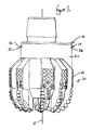
- the bottom hole assembly (BHA) illustrated, diagrammatically, in FIG. 1 comprises a drill bit 10 of the rotary drag type which has an axis 12 about which it is rotated, in use, and a gauge region 14 .
- the gauge region bears against the wall 16 of the wellbore, in use.
- the drill bit 10 is mounted upon a caliper tool 18 which comprises a body of diameter slightly smaller than the diameter of the gauge region 14 of the drill bit 10 .
- a caliper tool 18 which comprises a body of diameter slightly smaller than the diameter of the gauge region 14 of the drill bit 10 .
- the body 20 is slightly smaller in diameter than the gauge region 14 , it will be appreciated that, when the bottom hole assembly is in a straight part of the wellbore, the tool body 20 is radially spaced from the wall 16 of the wellbore.
- the body 20 has mounted thereon three accelerometers or, acceleration sensors 22 .
- Two of the sensors 22 are mounted at the periphery of the body 20 and lie upon a diameter of the body 20 . These two sensors are denoted by the reference numerals 24 , 26 .
- these sensors 24 , 26 are oppositely orientated with respect to the longitudinal axis 12 relative to one another and a sensitive to lateral acceleration of the body 20 in a first direction 25 , and to be sensitive to angular acceleration of the tool body 20 .
- oppositely mount sensors 24 , 26 it would be appreciated that other mounting orientations are also possible, as indicated by numeral 26 a , and in certain applications, these alternate orientations may be useful.
- the third sensor, denoted by reference numeral 28 is orientated to measure lateral acceleration in a direction 29 perpendicular to, or orthogonal to, the first direction 25 in which the sensors 24 , 26 are sensitive to lateral acceleration.
- the tool body 20 is connected to a drill string 30 which supports the bottom hole assembly.
- the bottom hole assembly may include a number of other components.
- it may include a stabilizer 32 , a mud pulse telemetry transmitter 34 and where the system of which the bottom hole assembly fobs part takes the form of a steerable drilling system then the bottom hole assembly may include a bias unit 36 arranged to apply a side loading to the drill bit 10 to cause the formation of a curve in the wellbore (as shown), or it may include a downhole motor for rotating the drill bit, and a bent component positionable, by controlling the angular position of the drill string, to control the direction in which drilling is taking place.
- the caliper tool 18 In use, while drilling is taking place, the caliper tool 18 is controlled in such a manner as to produce, sensor readings representative of the accelerations experienced by the tool 18 . By double integration of the sensor readings, the sensor readings can be converted into data representative of the radial position of the tool 18 relative to the wall 16 of the wellbore.
- the positions of the accelerometers 24 relative to the drill bit 10 are known and fixed. If the position of the wall 16 relative to the sensors is known, and the positions of the sensors are known, then the absolute position and shape of the wall 16 of the wellbore can be determined.
- the drill bit 10 should normally lie substantially on the axis of the part of the bore being drilled.
- the tool 18 should not engage the wall 16 of the wellbore, and so any acceleration of the tool body should be as a result of instructions modifying the drilling parameters, for example changing the direction of drilling, and as these accelerations are expected, they can be accounted for and can, if desired, be used to monitor the effect of alteration of the drilling parameters.
- the bottom hole assembly is not located within a straight part of the bore, then the tool body 20 may move into contact with the wall of the borehole. In these circumstances, the sensors will produce signals representative of the accelerations experienced by the tool 18 occurring as a result of the tool body 20 colliding or otherwise engaging with the wall of the wellbore.
- the acceleration readings are double integrated to produce data representative of the positions of the sensors 22 at the time that the accelerations were sensed.
- the positions of the sensors 22 are fixed relative to the drill bit, and as some information about the position of the drill bit is known, for example the distance downhole of the drill bit and the fact that it lies on the axis of the wellbore, a three-dimensional image of the wellbore can be derived. Since the drill bit 10 creates and defines the wall 16 of the wellbore as the bit drills, dimensional information of the wall 16 (i.e. the caliper) is readily determined knowing the position information gained from the sensors 22 , and the geometrical relationship between the sensors and the drill bit 10 .
- the constant acceleration due to gravity can be derived from the sensor signals. This information is used to align the three-dimensional image angularly, with respect to the longitudinal axis of the wellbore. If the wellbore is vertical, a magnetometer 38 may, be used to angularly align the three-dimensional image.
- the three-dimensional image must also be located properly along the length of the drill string. This is readily accomplished by monitoring the distance downhole of the drill bit.
- the caliper tool 18 may be operated in several ways. In a simple mode of operation, the caliper tool 18 may simply store the acceleration readings for subsequent interpretation once the tool 18 has been returned to the surface. Alternatively, the tool may be arranged to process the data to determine the shape of the bore as the readings are being made. In either case, if desired, the tool 18 may be connected to a system for transmitting data, either in its raw form or its processed form, to the surface to enable an operator to see the shape of the wellbore while the tool 18 is within the wellbore. Typically, such transmission of data could be performed using a mud pulse telemetry technique and the transmitter 34 .
- the apparatus may be designed or controlled in such a manner as to permit sensor readings to be taken relatively infrequently where it is sensed that the wellbore is relatively straight or where the tool occupies a portion of the wellbore of little interest to the operator, the frequency of taking readings, and hence the quality of the data resolution, increasing when it is sensed that the tool occupies a non-straight portion of the wellbore or the tool is located within a portion of the wellbore of greater interest to the operator.
- the tool body 20 is of diameter and position such that it does not engage the wellbore when the bottom hole assembly is located within a straight part of the wellbore, this need not be the case.
- the tool body could be designed in such a manner as to promote engagement between the tool body and the wall of the wellbore in order to increase the number of positive accelerometer readings.
- the tool body 20 could be located eccentrically relative to the axis of the drill bit as shown in FIG. 3 . In such circumstances, the shape and position of the tool body must be taken into account when interpreting the sensor readings.
- the caliper tool body 20 may form part of the drill bit 10 (also as shown in FIG. 3 ).
Abstract
Description
Claims (9)
Priority Applications (6)
| Application Number | Priority Date | Filing Date | Title |
|---|---|---|---|
| US09/841,659 US6467341B1 (en) | 2001-04-24 | 2001-04-24 | Accelerometer caliper while drilling |
| DE60237489T DE60237489D1 (en) | 2001-04-24 | 2002-04-11 | Caliber measurement during drilling by means of acceleration measurement |
| AT02252599T ATE479825T1 (en) | 2001-04-24 | 2002-04-11 | CALIBER MEASUREMENT DURING DRILLING USING ACCELERATION MEASUREMENT |
| EP02252599A EP1253285B1 (en) | 2001-04-24 | 2002-04-11 | Accelerometer caliper while drilling |
| NO20021817A NO20021817L (en) | 2001-04-24 | 2002-04-18 | Accelerometer, caliper for drilling arrangement |
| CA002382974A CA2382974C (en) | 2001-04-24 | 2002-04-23 | Accelerometer caliper while drilling |
Applications Claiming Priority (1)
| Application Number | Priority Date | Filing Date | Title |
|---|---|---|---|
| US09/841,659 US6467341B1 (en) | 2001-04-24 | 2001-04-24 | Accelerometer caliper while drilling |
Publications (2)
| Publication Number | Publication Date |
|---|---|
| US6467341B1 true US6467341B1 (en) | 2002-10-22 |
| US20020152806A1 US20020152806A1 (en) | 2002-10-24 |
Family
ID=25285409
Family Applications (1)
| Application Number | Title | Priority Date | Filing Date |
|---|---|---|---|
| US09/841,659 Expired - Lifetime US6467341B1 (en) | 2001-04-24 | 2001-04-24 | Accelerometer caliper while drilling |
Country Status (6)
| Country | Link |
|---|---|
| US (1) | US6467341B1 (en) |
| EP (1) | EP1253285B1 (en) |
| AT (1) | ATE479825T1 (en) |
| CA (1) | CA2382974C (en) |
| DE (1) | DE60237489D1 (en) |
| NO (1) | NO20021817L (en) |
Cited By (28)
| Publication number | Priority date | Publication date | Assignee | Title |
|---|---|---|---|---|
| US20050269082A1 (en) * | 2004-06-07 | 2005-12-08 | Pathfinder Energy Services, Inc. | Control method for downhole steering tool |
| US20060113111A1 (en) * | 2004-12-01 | 2006-06-01 | Ruben Martinez | System, apparatus, and method of conducting measurements of a borehole |
| US20070060152A1 (en) * | 2003-04-16 | 2007-03-15 | Sharp Kabushiki Kaisha | Wireless terminal, base device, wireless system, wireless terminal control method, wireless terminal control program, and computer-readable storage medium storing same program |
| US20070114062A1 (en) * | 2005-11-21 | 2007-05-24 | Hall David R | Drill Bit Assembly with a Logging Device |
| US20090063055A1 (en) * | 2007-08-30 | 2009-03-05 | Precision Energy Services, Inc. | System and Method for Obtaining and Using Downhole Data During Well Control Operations |
| US7866416B2 (en) | 2007-06-04 | 2011-01-11 | Schlumberger Technology Corporation | Clutch for a jack element |
| US20110042074A1 (en) * | 2007-09-13 | 2011-02-24 | Goldberg David S | Methods of Long-Term Gravimetric Monitoring of Carbon Dioxide Storage in Geological Formations |
| US20110060527A1 (en) * | 2009-09-10 | 2011-03-10 | Baker Hughes Incorporated | Drill Bit with Rate of Penetration Sensor |
| US7954401B2 (en) | 2006-10-27 | 2011-06-07 | Schlumberger Technology Corporation | Method of assembling a drill bit with a jack element |
| US7967083B2 (en) | 2007-09-06 | 2011-06-28 | Schlumberger Technology Corporation | Sensor for determining a position of a jack element |
| US8011457B2 (en) | 2006-03-23 | 2011-09-06 | Schlumberger Technology Corporation | Downhole hammer assembly |
| US8020471B2 (en) | 2005-11-21 | 2011-09-20 | Schlumberger Technology Corporation | Method for manufacturing a drill bit |
| US8225883B2 (en) | 2005-11-21 | 2012-07-24 | Schlumberger Technology Corporation | Downhole percussive tool with alternating pressure differentials |
| US8267196B2 (en) | 2005-11-21 | 2012-09-18 | Schlumberger Technology Corporation | Flow guide actuation |
| US8281882B2 (en) | 2005-11-21 | 2012-10-09 | Schlumberger Technology Corporation | Jack element for a drill bit |
| US8297378B2 (en) | 2005-11-21 | 2012-10-30 | Schlumberger Technology Corporation | Turbine driven hammer that oscillates at a constant frequency |
| US8297375B2 (en) | 2005-11-21 | 2012-10-30 | Schlumberger Technology Corporation | Downhole turbine |
| US8316964B2 (en) | 2006-03-23 | 2012-11-27 | Schlumberger Technology Corporation | Drill bit transducer device |
| US8360174B2 (en) | 2006-03-23 | 2013-01-29 | Schlumberger Technology Corporation | Lead the bit rotary steerable tool |
| US8499857B2 (en) | 2007-09-06 | 2013-08-06 | Schlumberger Technology Corporation | Downhole jack assembly sensor |
| US8522897B2 (en) | 2005-11-21 | 2013-09-03 | Schlumberger Technology Corporation | Lead the bit rotary steerable tool |
| US8528664B2 (en) | 2005-11-21 | 2013-09-10 | Schlumberger Technology Corporation | Downhole mechanism |
| WO2013138766A1 (en) * | 2012-03-16 | 2013-09-19 | Baker Hughes Incorporated | Apparatus and methods for determining whirl of a rotating tool |
| US8701799B2 (en) | 2009-04-29 | 2014-04-22 | Schlumberger Technology Corporation | Drill bit cutter pocket restitution |
| US8950517B2 (en) | 2005-11-21 | 2015-02-10 | Schlumberger Technology Corporation | Drill bit with a retained jack element |
| US10473812B2 (en) | 2016-12-14 | 2019-11-12 | Rock Visualization Technology, Llc | Gamma ray image logging tool sensor placement |
| US11500121B1 (en) | 2021-07-29 | 2022-11-15 | Rock Visualization Technology, Llc | Gamma ray logging tool assembly |
| US11608735B2 (en) | 2018-04-27 | 2023-03-21 | Halliburton Energy Services, Inc. | Drill bit position measurement |
Families Citing this family (4)
| Publication number | Priority date | Publication date | Assignee | Title |
|---|---|---|---|---|
| US8245792B2 (en) * | 2008-08-26 | 2012-08-21 | Baker Hughes Incorporated | Drill bit with weight and torque sensors and method of making a drill bit |
| US9567844B2 (en) * | 2013-10-10 | 2017-02-14 | Weatherford Technology Holdings, Llc | Analysis of drillstring dynamics using angular and linear motion data from multiple accelerometer pairs |
| US11566519B2 (en) * | 2020-03-12 | 2023-01-31 | Saudi Arabian Oil Company | Laser-based monitoring tool |
| US11466559B2 (en) * | 2020-07-31 | 2022-10-11 | Baker Hughes Oilfield Operations Llc | Downhole tool sensor arrangements and associated methods and systems |
Citations (71)
| Publication number | Priority date | Publication date | Assignee | Title |
|---|---|---|---|---|
| US1819923A (en) | 1928-10-26 | 1931-08-18 | Schlumberger Prospection | Electrical process and apparatus for the determination of the nature of the geological formations traversed by drill holes |
| US1913293A (en) | 1931-09-02 | 1933-06-06 | Schlumberger Conrad | Electrical process for the geological investigation of the porous strata traversed by drill holes |
| US2476137A (en) | 1942-05-16 | 1949-07-12 | Schlumberger Well Surv Corp | Method of positioning apparatus in boreholes |
| US2524031A (en) | 1945-10-01 | 1950-10-03 | Jan J Arps | Apparatus for logging wells |
| US2573137A (en) | 1950-04-21 | 1951-10-30 | Halliburton Oil Well Cementing | Electric well logging system |
| US2677790A (en) | 1951-12-05 | 1954-05-04 | Jan J Arps | Borehole logging by intermittent signaling |
| US2925251A (en) | 1954-03-05 | 1960-02-16 | Jan J Arps | Earth well borehole drilling and logging system |
| US3058532A (en) | 1953-07-15 | 1962-10-16 | Dresser Ind | Drill bit condition indicator and signaling system |
| US3345867A (en) | 1964-09-03 | 1967-10-10 | Arps Corp | Method and apparatus for measuring rock bit wear while drilling |
| US3455158A (en) | 1967-11-29 | 1969-07-15 | Texaco Inc | Logging while drilling system |
| US4095865A (en) | 1977-05-23 | 1978-06-20 | Shell Oil Company | Telemetering drill string with piped electrical conductor |
| US4216536A (en) | 1978-10-10 | 1980-08-05 | Exploration Logging, Inc. | Transmitting well logging data |
| US4324297A (en) | 1980-07-03 | 1982-04-13 | Shell Oil Company | Steering drill string |
| US4346591A (en) | 1981-08-21 | 1982-08-31 | Evans Robert F | Sensing impending sealed bearing and gage failure |
| US4445734A (en) | 1981-12-04 | 1984-05-01 | Hughes Tool Company | Telemetry drill pipe with pressure sensitive contacts |
| US4445578A (en) | 1979-02-28 | 1984-05-01 | Standard Oil Company (Indiana) | System for measuring downhole drilling forces |
| US4455278A (en) | 1980-12-02 | 1984-06-19 | Skf Industrial Trading & Development Company, B.V. | Method for producing an object on which an exterior layer is applied by thermal spraying and object, in particular a drill bit, obtained pursuant to this method |
| US4496203A (en) | 1981-05-22 | 1985-01-29 | Coal Industry (Patents) Limited | Drill pipe sections |
| US4518888A (en) | 1982-12-27 | 1985-05-21 | Nl Industries, Inc. | Downhole apparatus for absorbing vibratory energy to generate electrical power |
| US4557538A (en) | 1982-07-21 | 1985-12-10 | Institut Francais Du Petrole | Assembly for effecting an electric connection through a pipe formed of several elements |
| US4599904A (en) * | 1984-10-02 | 1986-07-15 | Nl Industries, Inc. | Method for determining borehole stress from MWD parameter and caliper measurements |
| US4662458A (en) | 1985-10-23 | 1987-05-05 | Nl Industries, Inc. | Method and apparatus for bottom hole measurement |
| US4697650A (en) * | 1984-09-24 | 1987-10-06 | Nl Industries, Inc. | Method for estimating formation characteristics of the exposed bottomhole formation |
| US4788544A (en) | 1987-01-08 | 1988-11-29 | Hughes Tool Company - Usa | Well bore data transmission system |
| US4829489A (en) | 1988-06-01 | 1989-05-09 | Western Atlas International, Inc. | Method of determining drill string velocity |
| US4884071A (en) | 1987-01-08 | 1989-11-28 | Hughes Tool Company | Wellbore tool with hall effect coupling |
| US4903245A (en) | 1988-03-11 | 1990-02-20 | Exploration Logging, Inc. | Downhole vibration monitoring of a drillstring |
| US4914433A (en) | 1988-04-19 | 1990-04-03 | Hughes Tool Company | Conductor system for well bore data transmission |
| US4958125A (en) | 1988-12-03 | 1990-09-18 | Anadrill, Inc. | Method and apparatus for determining characteristics of the movement of a rotating drill string including rotation speed and lateral shocks |
| US4958517A (en) | 1989-08-07 | 1990-09-25 | Teleco Oilfield Services Inc. | Apparatus for measuring weight, torque and side force on a drill bit |
| US5058077A (en) | 1990-10-09 | 1991-10-15 | Baroid Technology, Inc. | Compensation technique for eccentered MWD sensors |
| US5091644A (en) | 1991-01-15 | 1992-02-25 | Teleco Oilfield Services Inc. | Method for analyzing formation data from a formation evaluation MWD logging tool |
| US5160925A (en) | 1991-04-17 | 1992-11-03 | Smith International, Inc. | Short hop communication link for downhole mwd system |
| EP0558379A1 (en) | 1992-02-27 | 1993-09-01 | Institut Francais Du Petrole | System and method for physical data acquisition during drilling |
| US5313829A (en) | 1992-01-03 | 1994-05-24 | Atlantic Richfield Company | Method of determining drillstring bottom hole assembly vibrations |
| US5358059A (en) * | 1993-09-27 | 1994-10-25 | Ho Hwa Shan | Apparatus and method for the dynamic measurement of a drill string employed in drilling |
| US5473158A (en) | 1994-01-14 | 1995-12-05 | Schlumberger Technology Corporation | Logging while drilling method and apparatus for measuring formation characteristics as a function of angular position within a borehole |
| US5475309A (en) | 1994-01-21 | 1995-12-12 | Atlantic Richfield Company | Sensor in bit for measuring formation properties while drilling including a drilling fluid ejection nozzle for ejecting a uniform layer of fluid over the sensor |
| US5501285A (en) | 1993-07-20 | 1996-03-26 | Lamine; Etienne | Method for controlling the head of a drilling or core-drilling device and apparatus for carrying out this method |
| US5507353A (en) | 1993-12-08 | 1996-04-16 | Institut Francais Du Petrole | Method and system for controlling the rotary speed stability of a drill bit |
| US5511037A (en) | 1993-10-22 | 1996-04-23 | Baker Hughes Incorporated | Comprehensive method of processing measurement while drilling data from one or more sensors |
| US5550788A (en) | 1994-05-24 | 1996-08-27 | Institut Francais Du Petrole | Method and system of analysis of the behavior of a drill string |
| EP0728915A2 (en) | 1995-02-16 | 1996-08-28 | Baker Hughes Incorporated | Method and apparatus for monitoring and recording of operating conditions of a downhole drill bit during drilling operations |
| US5565624A (en) | 1993-01-27 | 1996-10-15 | Elf Aquitaine Production | Method of determining variations in the morphology of a borehole |
| US5581024A (en) | 1994-10-20 | 1996-12-03 | Baker Hughes Incorporated | Downhole depth correlation and computation apparatus and methods for combining multiple borehole measurements |
| US5629623A (en) | 1992-07-30 | 1997-05-13 | Schlumberger Technology Corporation | Pulsed nuclear magnetism tool for formation evaluation while drilling |
| US5654503A (en) | 1994-10-19 | 1997-08-05 | Schlumberger Technology Corporation | Method and apparatus for improved measurement of drilling conditions |
| US5663929A (en) | 1994-05-24 | 1997-09-02 | Institut Francais Du Petrole | Drilling signal transmission method and system |
| US5705927A (en) | 1992-07-30 | 1998-01-06 | Schlumberger Technology Corporation | Pulsed nuclear magnetism tool for formation evaluation while drilling including a shortened or truncated CPMG sequence |
| US5720355A (en) | 1993-07-20 | 1998-02-24 | Baroid Technology, Inc. | Drill bit instrumentation and method for controlling drilling or core-drilling |
| US5721376A (en) | 1995-03-31 | 1998-02-24 | Institut Francais Du Petrole | Method and system for predicting the appearance of a dysfunctioning during drilling |
| US5740036A (en) | 1995-09-15 | 1998-04-14 | Atlantic Richfield Company | Method and apparatus for analyzing geological data using wavelet analysis |
| WO1998017894A2 (en) | 1996-10-22 | 1998-04-30 | Baker Hughes Incorporated | Drilling system with integrated bottom hole assembly |
| US5748471A (en) | 1996-03-29 | 1998-05-05 | Otatco, Inc. | Well collar identification method |
| US5842149A (en) | 1996-10-22 | 1998-11-24 | Baker Hughes Incorporated | Closed loop drilling system |
| US5883583A (en) | 1997-07-16 | 1999-03-16 | Schlumberger Technology Corporation | Imaging a completion string in a wellbore |
| US5886303A (en) | 1997-10-20 | 1999-03-23 | Dresser Industries, Inc. | Method and apparatus for cancellation of unwanted signals in MWD acoustic tools |
| US5899958A (en) | 1995-09-11 | 1999-05-04 | Halliburton Energy Services, Inc. | Logging while drilling borehole imaging and dipmeter device |
| US5923167A (en) | 1992-07-30 | 1999-07-13 | Schlumberger Technology Corporation | Pulsed nuclear magnetism tool for formation evaluation while drilling |
| WO1999036801A1 (en) | 1998-01-16 | 1999-07-22 | Numar Corporation | Method and apparatus for nuclear magnetic resonance measuring while drilling |
| US5947213A (en) | 1996-12-02 | 1999-09-07 | Intelligent Inspection Corporation | Downhole tools using artificial intelligence based control |
| US5987385A (en) | 1997-08-29 | 1999-11-16 | Dresser Industries, Inc. | Method and apparatus for creating an image of an earth borehole or a well casing |
| US6008646A (en) | 1996-04-17 | 1999-12-28 | Schlumberger Technology Corporation | Apparatus for protecting a magnetic resonance antenna |
| US6023164A (en) | 1998-02-20 | 2000-02-08 | Numar Corporation | Eccentric NMR well logging apparatus and method |
| US6057784A (en) | 1997-09-02 | 2000-05-02 | Schlumberger Technology Corporatioin | Apparatus and system for making at-bit measurements while drilling |
| US6065219A (en) | 1998-06-26 | 2000-05-23 | Dresser Industries, Inc. | Method and apparatus for determining the shape of an earth borehole and the motion of a tool within the borehole |
| US6081116A (en) | 1997-04-21 | 2000-06-27 | Baker Hughes Incorporated | Nuclear magnetic resonance apparatus and method for geological applications |
| US6111408A (en) | 1997-12-23 | 2000-08-29 | Numar Corporation | Nuclear magnetic resonance sensing apparatus and techniques for downhole measurements |
| US6109372A (en) | 1999-03-15 | 2000-08-29 | Schlumberger Technology Corporation | Rotary steerable well drilling system utilizing hydraulic servo-loop |
| US6158529A (en) | 1998-12-11 | 2000-12-12 | Schlumberger Technology Corporation | Rotary steerable well drilling system utilizing sliding sleeve |
| US6205851B1 (en) * | 1998-05-05 | 2001-03-27 | Baker Hughes Incorporated | Method for determining drill collar whirl in a bottom hole assembly and method for determining borehole size |
-
2001
- 2001-04-24 US US09/841,659 patent/US6467341B1/en not_active Expired - Lifetime
-
2002
- 2002-04-11 DE DE60237489T patent/DE60237489D1/en not_active Expired - Lifetime
- 2002-04-11 AT AT02252599T patent/ATE479825T1/en not_active IP Right Cessation
- 2002-04-11 EP EP02252599A patent/EP1253285B1/en not_active Expired - Lifetime
- 2002-04-18 NO NO20021817A patent/NO20021817L/en not_active Application Discontinuation
- 2002-04-23 CA CA002382974A patent/CA2382974C/en not_active Expired - Lifetime
Patent Citations (75)
| Publication number | Priority date | Publication date | Assignee | Title |
|---|---|---|---|---|
| US1819923A (en) | 1928-10-26 | 1931-08-18 | Schlumberger Prospection | Electrical process and apparatus for the determination of the nature of the geological formations traversed by drill holes |
| US1913293A (en) | 1931-09-02 | 1933-06-06 | Schlumberger Conrad | Electrical process for the geological investigation of the porous strata traversed by drill holes |
| US2476137A (en) | 1942-05-16 | 1949-07-12 | Schlumberger Well Surv Corp | Method of positioning apparatus in boreholes |
| US2524031A (en) | 1945-10-01 | 1950-10-03 | Jan J Arps | Apparatus for logging wells |
| US2573137A (en) | 1950-04-21 | 1951-10-30 | Halliburton Oil Well Cementing | Electric well logging system |
| US2677790A (en) | 1951-12-05 | 1954-05-04 | Jan J Arps | Borehole logging by intermittent signaling |
| US3058532A (en) | 1953-07-15 | 1962-10-16 | Dresser Ind | Drill bit condition indicator and signaling system |
| US2925251A (en) | 1954-03-05 | 1960-02-16 | Jan J Arps | Earth well borehole drilling and logging system |
| US3345867A (en) | 1964-09-03 | 1967-10-10 | Arps Corp | Method and apparatus for measuring rock bit wear while drilling |
| US3455158A (en) | 1967-11-29 | 1969-07-15 | Texaco Inc | Logging while drilling system |
| US4095865A (en) | 1977-05-23 | 1978-06-20 | Shell Oil Company | Telemetering drill string with piped electrical conductor |
| US4216536A (en) | 1978-10-10 | 1980-08-05 | Exploration Logging, Inc. | Transmitting well logging data |
| US4445578A (en) | 1979-02-28 | 1984-05-01 | Standard Oil Company (Indiana) | System for measuring downhole drilling forces |
| US4324297A (en) | 1980-07-03 | 1982-04-13 | Shell Oil Company | Steering drill string |
| US4455278A (en) | 1980-12-02 | 1984-06-19 | Skf Industrial Trading & Development Company, B.V. | Method for producing an object on which an exterior layer is applied by thermal spraying and object, in particular a drill bit, obtained pursuant to this method |
| US4496203A (en) | 1981-05-22 | 1985-01-29 | Coal Industry (Patents) Limited | Drill pipe sections |
| US4346591A (en) | 1981-08-21 | 1982-08-31 | Evans Robert F | Sensing impending sealed bearing and gage failure |
| US4445734A (en) | 1981-12-04 | 1984-05-01 | Hughes Tool Company | Telemetry drill pipe with pressure sensitive contacts |
| US4557538A (en) | 1982-07-21 | 1985-12-10 | Institut Francais Du Petrole | Assembly for effecting an electric connection through a pipe formed of several elements |
| US4518888A (en) | 1982-12-27 | 1985-05-21 | Nl Industries, Inc. | Downhole apparatus for absorbing vibratory energy to generate electrical power |
| US4697650A (en) * | 1984-09-24 | 1987-10-06 | Nl Industries, Inc. | Method for estimating formation characteristics of the exposed bottomhole formation |
| US4599904A (en) * | 1984-10-02 | 1986-07-15 | Nl Industries, Inc. | Method for determining borehole stress from MWD parameter and caliper measurements |
| US4662458A (en) | 1985-10-23 | 1987-05-05 | Nl Industries, Inc. | Method and apparatus for bottom hole measurement |
| US4788544A (en) | 1987-01-08 | 1988-11-29 | Hughes Tool Company - Usa | Well bore data transmission system |
| US4884071A (en) | 1987-01-08 | 1989-11-28 | Hughes Tool Company | Wellbore tool with hall effect coupling |
| US4903245A (en) | 1988-03-11 | 1990-02-20 | Exploration Logging, Inc. | Downhole vibration monitoring of a drillstring |
| US4914433A (en) | 1988-04-19 | 1990-04-03 | Hughes Tool Company | Conductor system for well bore data transmission |
| US4829489A (en) | 1988-06-01 | 1989-05-09 | Western Atlas International, Inc. | Method of determining drill string velocity |
| US4958125A (en) | 1988-12-03 | 1990-09-18 | Anadrill, Inc. | Method and apparatus for determining characteristics of the movement of a rotating drill string including rotation speed and lateral shocks |
| US4958517A (en) | 1989-08-07 | 1990-09-25 | Teleco Oilfield Services Inc. | Apparatus for measuring weight, torque and side force on a drill bit |
| US5058077A (en) | 1990-10-09 | 1991-10-15 | Baroid Technology, Inc. | Compensation technique for eccentered MWD sensors |
| US5091644A (en) | 1991-01-15 | 1992-02-25 | Teleco Oilfield Services Inc. | Method for analyzing formation data from a formation evaluation MWD logging tool |
| US5160925A (en) | 1991-04-17 | 1992-11-03 | Smith International, Inc. | Short hop communication link for downhole mwd system |
| US5160925C1 (en) | 1991-04-17 | 2001-03-06 | Halliburton Co | Short hop communication link for downhole mwd system |
| US5313829A (en) | 1992-01-03 | 1994-05-24 | Atlantic Richfield Company | Method of determining drillstring bottom hole assembly vibrations |
| US5402677A (en) * | 1992-01-03 | 1995-04-04 | Atlantic Richfield Company | Method of determining drillstring bottom hole assembly vibrations |
| EP0558379A1 (en) | 1992-02-27 | 1993-09-01 | Institut Francais Du Petrole | System and method for physical data acquisition during drilling |
| US5923167A (en) | 1992-07-30 | 1999-07-13 | Schlumberger Technology Corporation | Pulsed nuclear magnetism tool for formation evaluation while drilling |
| US5705927A (en) | 1992-07-30 | 1998-01-06 | Schlumberger Technology Corporation | Pulsed nuclear magnetism tool for formation evaluation while drilling including a shortened or truncated CPMG sequence |
| US5629623A (en) | 1992-07-30 | 1997-05-13 | Schlumberger Technology Corporation | Pulsed nuclear magnetism tool for formation evaluation while drilling |
| US5565624A (en) | 1993-01-27 | 1996-10-15 | Elf Aquitaine Production | Method of determining variations in the morphology of a borehole |
| US5501285A (en) | 1993-07-20 | 1996-03-26 | Lamine; Etienne | Method for controlling the head of a drilling or core-drilling device and apparatus for carrying out this method |
| US5720355A (en) | 1993-07-20 | 1998-02-24 | Baroid Technology, Inc. | Drill bit instrumentation and method for controlling drilling or core-drilling |
| US5358059A (en) * | 1993-09-27 | 1994-10-25 | Ho Hwa Shan | Apparatus and method for the dynamic measurement of a drill string employed in drilling |
| US5511037A (en) | 1993-10-22 | 1996-04-23 | Baker Hughes Incorporated | Comprehensive method of processing measurement while drilling data from one or more sensors |
| US5507353A (en) | 1993-12-08 | 1996-04-16 | Institut Francais Du Petrole | Method and system for controlling the rotary speed stability of a drill bit |
| US5513528A (en) | 1994-01-14 | 1996-05-07 | Schlumberger Technology Corporation | Logging while drilling method and apparatus for measuring standoff as a function of angular position within a borehole |
| US5473158A (en) | 1994-01-14 | 1995-12-05 | Schlumberger Technology Corporation | Logging while drilling method and apparatus for measuring formation characteristics as a function of angular position within a borehole |
| US6150822A (en) | 1994-01-21 | 2000-11-21 | Atlantic Richfield Company | Sensor in bit for measuring formation properties while drilling |
| US5475309A (en) | 1994-01-21 | 1995-12-12 | Atlantic Richfield Company | Sensor in bit for measuring formation properties while drilling including a drilling fluid ejection nozzle for ejecting a uniform layer of fluid over the sensor |
| US5550788A (en) | 1994-05-24 | 1996-08-27 | Institut Francais Du Petrole | Method and system of analysis of the behavior of a drill string |
| US5663929A (en) | 1994-05-24 | 1997-09-02 | Institut Francais Du Petrole | Drilling signal transmission method and system |
| US5654503A (en) | 1994-10-19 | 1997-08-05 | Schlumberger Technology Corporation | Method and apparatus for improved measurement of drilling conditions |
| US5581024A (en) | 1994-10-20 | 1996-12-03 | Baker Hughes Incorporated | Downhole depth correlation and computation apparatus and methods for combining multiple borehole measurements |
| EP0728915A2 (en) | 1995-02-16 | 1996-08-28 | Baker Hughes Incorporated | Method and apparatus for monitoring and recording of operating conditions of a downhole drill bit during drilling operations |
| US5721376A (en) | 1995-03-31 | 1998-02-24 | Institut Francais Du Petrole | Method and system for predicting the appearance of a dysfunctioning during drilling |
| US5899958A (en) | 1995-09-11 | 1999-05-04 | Halliburton Energy Services, Inc. | Logging while drilling borehole imaging and dipmeter device |
| US5740036A (en) | 1995-09-15 | 1998-04-14 | Atlantic Richfield Company | Method and apparatus for analyzing geological data using wavelet analysis |
| US5748471A (en) | 1996-03-29 | 1998-05-05 | Otatco, Inc. | Well collar identification method |
| US6008646A (en) | 1996-04-17 | 1999-12-28 | Schlumberger Technology Corporation | Apparatus for protecting a magnetic resonance antenna |
| US5842149A (en) | 1996-10-22 | 1998-11-24 | Baker Hughes Incorporated | Closed loop drilling system |
| WO1998017894A2 (en) | 1996-10-22 | 1998-04-30 | Baker Hughes Incorporated | Drilling system with integrated bottom hole assembly |
| US5947213A (en) | 1996-12-02 | 1999-09-07 | Intelligent Inspection Corporation | Downhole tools using artificial intelligence based control |
| US6081116A (en) | 1997-04-21 | 2000-06-27 | Baker Hughes Incorporated | Nuclear magnetic resonance apparatus and method for geological applications |
| US5883583A (en) | 1997-07-16 | 1999-03-16 | Schlumberger Technology Corporation | Imaging a completion string in a wellbore |
| US5987385A (en) | 1997-08-29 | 1999-11-16 | Dresser Industries, Inc. | Method and apparatus for creating an image of an earth borehole or a well casing |
| US6057784A (en) | 1997-09-02 | 2000-05-02 | Schlumberger Technology Corporatioin | Apparatus and system for making at-bit measurements while drilling |
| US5886303A (en) | 1997-10-20 | 1999-03-23 | Dresser Industries, Inc. | Method and apparatus for cancellation of unwanted signals in MWD acoustic tools |
| US6111408A (en) | 1997-12-23 | 2000-08-29 | Numar Corporation | Nuclear magnetic resonance sensing apparatus and techniques for downhole measurements |
| WO1999036801A1 (en) | 1998-01-16 | 1999-07-22 | Numar Corporation | Method and apparatus for nuclear magnetic resonance measuring while drilling |
| US6023164A (en) | 1998-02-20 | 2000-02-08 | Numar Corporation | Eccentric NMR well logging apparatus and method |
| US6205851B1 (en) * | 1998-05-05 | 2001-03-27 | Baker Hughes Incorporated | Method for determining drill collar whirl in a bottom hole assembly and method for determining borehole size |
| US6065219A (en) | 1998-06-26 | 2000-05-23 | Dresser Industries, Inc. | Method and apparatus for determining the shape of an earth borehole and the motion of a tool within the borehole |
| US6158529A (en) | 1998-12-11 | 2000-12-12 | Schlumberger Technology Corporation | Rotary steerable well drilling system utilizing sliding sleeve |
| US6109372A (en) | 1999-03-15 | 2000-08-29 | Schlumberger Technology Corporation | Rotary steerable well drilling system utilizing hydraulic servo-loop |
Non-Patent Citations (1)
| Title |
|---|
| Leggett III; Dubinsky; Patterson; Bolshakov; "Field Test Results Demonstrating Improved Real-Time Data Quality in an Advanced LWD Acoustic System"; SPE 71732; 2001 SPE Annual Technical Conference and Exhibition held in New Orleans, Louisiana, Sep. 30-Oct. 3, 2001. English. |
Cited By (41)
| Publication number | Priority date | Publication date | Assignee | Title |
|---|---|---|---|---|
| US20070060152A1 (en) * | 2003-04-16 | 2007-03-15 | Sharp Kabushiki Kaisha | Wireless terminal, base device, wireless system, wireless terminal control method, wireless terminal control program, and computer-readable storage medium storing same program |
| US20050269082A1 (en) * | 2004-06-07 | 2005-12-08 | Pathfinder Energy Services, Inc. | Control method for downhole steering tool |
| US7669668B2 (en) * | 2004-12-01 | 2010-03-02 | Schlumberger Technology Corporation | System, apparatus, and method of conducting measurements of a borehole |
| US20060113111A1 (en) * | 2004-12-01 | 2006-06-01 | Ruben Martinez | System, apparatus, and method of conducting measurements of a borehole |
| US20100108386A1 (en) * | 2004-12-01 | 2010-05-06 | Ruben Martinez | System, apparatus, and method of conducting measurements of a borehole |
| US8978782B2 (en) | 2004-12-01 | 2015-03-17 | Schlumberger Technology Corporation | System, apparatus, and method of conducting measurements of a borehole |
| US8528664B2 (en) | 2005-11-21 | 2013-09-10 | Schlumberger Technology Corporation | Downhole mechanism |
| US8297375B2 (en) | 2005-11-21 | 2012-10-30 | Schlumberger Technology Corporation | Downhole turbine |
| US8408336B2 (en) | 2005-11-21 | 2013-04-02 | Schlumberger Technology Corporation | Flow guide actuation |
| US8950517B2 (en) | 2005-11-21 | 2015-02-10 | Schlumberger Technology Corporation | Drill bit with a retained jack element |
| US20070114062A1 (en) * | 2005-11-21 | 2007-05-24 | Hall David R | Drill Bit Assembly with a Logging Device |
| US7398837B2 (en) * | 2005-11-21 | 2008-07-15 | Hall David R | Drill bit assembly with a logging device |
| US8522897B2 (en) | 2005-11-21 | 2013-09-03 | Schlumberger Technology Corporation | Lead the bit rotary steerable tool |
| US8297378B2 (en) | 2005-11-21 | 2012-10-30 | Schlumberger Technology Corporation | Turbine driven hammer that oscillates at a constant frequency |
| US8020471B2 (en) | 2005-11-21 | 2011-09-20 | Schlumberger Technology Corporation | Method for manufacturing a drill bit |
| US8225883B2 (en) | 2005-11-21 | 2012-07-24 | Schlumberger Technology Corporation | Downhole percussive tool with alternating pressure differentials |
| US8267196B2 (en) | 2005-11-21 | 2012-09-18 | Schlumberger Technology Corporation | Flow guide actuation |
| US8281882B2 (en) | 2005-11-21 | 2012-10-09 | Schlumberger Technology Corporation | Jack element for a drill bit |
| US8011457B2 (en) | 2006-03-23 | 2011-09-06 | Schlumberger Technology Corporation | Downhole hammer assembly |
| US8316964B2 (en) | 2006-03-23 | 2012-11-27 | Schlumberger Technology Corporation | Drill bit transducer device |
| US8360174B2 (en) | 2006-03-23 | 2013-01-29 | Schlumberger Technology Corporation | Lead the bit rotary steerable tool |
| US7954401B2 (en) | 2006-10-27 | 2011-06-07 | Schlumberger Technology Corporation | Method of assembling a drill bit with a jack element |
| US8307919B2 (en) | 2007-06-04 | 2012-11-13 | Schlumberger Technology Corporation | Clutch for a jack element |
| US7866416B2 (en) | 2007-06-04 | 2011-01-11 | Schlumberger Technology Corporation | Clutch for a jack element |
| US8781746B2 (en) * | 2007-08-30 | 2014-07-15 | Precision Energy Services, Inc. | System and method for obtaining and using downhole data during well control operations |
| US20090063055A1 (en) * | 2007-08-30 | 2009-03-05 | Precision Energy Services, Inc. | System and Method for Obtaining and Using Downhole Data During Well Control Operations |
| US7967083B2 (en) | 2007-09-06 | 2011-06-28 | Schlumberger Technology Corporation | Sensor for determining a position of a jack element |
| US8499857B2 (en) | 2007-09-06 | 2013-08-06 | Schlumberger Technology Corporation | Downhole jack assembly sensor |
| US20110042074A1 (en) * | 2007-09-13 | 2011-02-24 | Goldberg David S | Methods of Long-Term Gravimetric Monitoring of Carbon Dioxide Storage in Geological Formations |
| US8438917B2 (en) * | 2007-09-13 | 2013-05-14 | The Trustees Of Columbia University In The City Of New York | Methods of long-term gravimetric monitoring of carbon dioxide storage in geological formations |
| US8701799B2 (en) | 2009-04-29 | 2014-04-22 | Schlumberger Technology Corporation | Drill bit cutter pocket restitution |
| US9238958B2 (en) * | 2009-09-10 | 2016-01-19 | Baker Hughes Incorporated | Drill bit with rate of penetration sensor |
| US20110060527A1 (en) * | 2009-09-10 | 2011-03-10 | Baker Hughes Incorporated | Drill Bit with Rate of Penetration Sensor |
| WO2013138766A1 (en) * | 2012-03-16 | 2013-09-19 | Baker Hughes Incorporated | Apparatus and methods for determining whirl of a rotating tool |
| US9410377B2 (en) | 2012-03-16 | 2016-08-09 | Baker Hughes Incorporated | Apparatus and methods for determining whirl of a rotating tool |
| US10473812B2 (en) | 2016-12-14 | 2019-11-12 | Rock Visualization Technology, Llc | Gamma ray image logging tool sensor placement |
| US10641919B2 (en) | 2016-12-14 | 2020-05-05 | Rock Visualization Technology, Llc | Passive cased well image logging |
| US10914860B2 (en) | 2016-12-14 | 2021-02-09 | Rock Visualization Technology, Llc | Gamma ray image logging tool sensor placement |
| US11163088B2 (en) | 2016-12-14 | 2021-11-02 | Rock Visualization Technology, Llc | Passive cased well image logging |
| US11608735B2 (en) | 2018-04-27 | 2023-03-21 | Halliburton Energy Services, Inc. | Drill bit position measurement |
| US11500121B1 (en) | 2021-07-29 | 2022-11-15 | Rock Visualization Technology, Llc | Gamma ray logging tool assembly |
Also Published As
| Publication number | Publication date |
|---|---|
| ATE479825T1 (en) | 2010-09-15 |
| EP1253285B1 (en) | 2010-09-01 |
| NO20021817D0 (en) | 2002-04-18 |
| US20020152806A1 (en) | 2002-10-24 |
| CA2382974A1 (en) | 2002-10-24 |
| EP1253285A3 (en) | 2003-07-16 |
| CA2382974C (en) | 2009-07-14 |
| DE60237489D1 (en) | 2010-10-14 |
| EP1253285A2 (en) | 2002-10-30 |
| NO20021817L (en) | 2002-10-25 |
Similar Documents
| Publication | Publication Date | Title |
|---|---|---|
| US6467341B1 (en) | Accelerometer caliper while drilling | |
| US7743654B2 (en) | System, method and apparatus for petrophysical and geophysical measurements at the drilling bit | |
| US5410303A (en) | System for drilling deivated boreholes | |
| US10533412B2 (en) | Phase estimation from rotating sensors to get a toolface | |
| US7389828B2 (en) | Apparatus and method for mechanical caliper measurements during drilling and logging-while-drilling operations | |
| US7114565B2 (en) | Measurement-while-drilling assembly using real-time toolface oriented measurements | |
| US6845563B2 (en) | Method and device for the measurement of the drift of a borchole | |
| CA2881918C (en) | Method and apparatus for communicating incremental depth and other useful data to downhole tool | |
| US9464519B2 (en) | Method and apparatus for detecting gamma radiation downhole | |
| US20070203651A1 (en) | Magnetic measurements while rotating | |
| US20030056381A1 (en) | Survey apparatus and methods for directional wellbore surveying | |
| EP1933171B1 (en) | Magnetometers for measurement-while-drilling applications | |
| GB2247477A (en) | Borehole drilling and telemetry | |
| US6898967B2 (en) | Azimuthal resistivity using a non-directional device | |
| US10472955B2 (en) | Method of providing continuous survey data while drilling | |
| US6552334B2 (en) | Wellbore caliper measurement method using measurements from a gamma-gamma density | |
| GB2377490A (en) | Using a gamma-gamma density instrument to determine wellbore diameter and shape |
Legal Events
| Date | Code | Title | Description |
|---|---|---|---|
| AS | Assignment |
Owner name: SCHLUMBERGER TECHNOLOGY CORPORATION, TEXAS Free format text: ASSIGNMENT OF ASSIGNORS INTEREST;ASSIGNORS:BOUCHER, MARCEL;MCCARTHY, TIM;JARVIS, BRIAN PETER;REEL/FRAME:012739/0818 Effective date: 20010723 |
|
| STCF | Information on status: patent grant |
Free format text: PATENTED CASE |
|
| AS | Assignment |
Owner name: REED HYCALOG OPERATING LP, TEXAS Free format text: ASSIGNMENT OF ASSIGNORS INTEREST;ASSIGNOR:SCHLUMBERGER TECHNOLOGY CORPORATION;REEL/FRAME:013506/0905 Effective date: 20021122 |
|
| AS | Assignment |
Owner name: DEUTSCHE BANK TRUST COMPANY AMERICAS, NEW YORK Free format text: GRANT OF PATENT (SECURITY AGREEMENT);ASSIGNOR:REED-HYCALOG OPERATING, L.P.;REEL/FRAME:013336/0691 Effective date: 20021219 |
|
| AS | Assignment |
Owner name: REEDHYCALOG, L.P., TEXAS Free format text: CHANGE OF NAME;ASSIGNOR:REED-HYCALOG OPERATING, L.P.;REEL/FRAME:016026/0020 Effective date: 20030122 |
|
| AS | Assignment |
Owner name: REED-HYCALOG OPERATING, L.P., TEXAS Free format text: RELEASE OF GRANT OF PATENT SECURITY AGREEMENT;ASSIGNOR:DEUTSCHE BANK TRUST COMPANY AMERICAS;REEL/FRAME:016079/0429 Effective date: 20050512 |
|
| AS | Assignment |
Owner name: WELLS FARGO BANK, TEXAS Free format text: SECURITY AGREEMENT;ASSIGNOR:REEDHYCALOG, L.P.;REEL/FRAME:016087/0681 Effective date: 20050512 |
|
| FPAY | Fee payment |
Year of fee payment: 4 |
|
| AS | Assignment |
Owner name: REED HYCALOG, UTAH, LLC., TEXAS Free format text: RELEASE OF PATENT SECURITY AGREEMENT;ASSIGNOR:WELLS FARGO BANK;REEL/FRAME:018463/0103 Effective date: 20060831 |
|
| AS | Assignment |
Owner name: REEDHYCALOG, L.P., TEXAS Free format text: CORRECTIVE ASSIGNMENT TO CORRECT THE RECEIVING PARTIES NAME, PREVIOUSLY RECORDED ON REEL 018463 FRAME 0103;ASSIGNOR:WELLS FARGO BANK;REEL/FRAME:018490/0732 Effective date: 20060831 |
|
| FPAY | Fee payment |
Year of fee payment: 8 |
|
| FPAY | Fee payment |
Year of fee payment: 12 |