US6471435B1 - Flexural joint - Google Patents
Flexural joint Download PDFInfo
- Publication number
- US6471435B1 US6471435B1 US09/543,283 US54328300A US6471435B1 US 6471435 B1 US6471435 B1 US 6471435B1 US 54328300 A US54328300 A US 54328300A US 6471435 B1 US6471435 B1 US 6471435B1
- Authority
- US
- United States
- Prior art keywords
- joint
- platform
- freedom
- flexure
- movement
- Prior art date
- Legal status (The legal status is an assumption and is not a legal conclusion. Google has not performed a legal analysis and makes no representation as to the accuracy of the status listed.)
- Expired - Fee Related
Links
Images


Classifications
-
- G—PHYSICS
- G03—PHOTOGRAPHY; CINEMATOGRAPHY; ANALOGOUS TECHNIQUES USING WAVES OTHER THAN OPTICAL WAVES; ELECTROGRAPHY; HOLOGRAPHY
- G03F—PHOTOMECHANICAL PRODUCTION OF TEXTURED OR PATTERNED SURFACES, e.g. FOR PRINTING, FOR PROCESSING OF SEMICONDUCTOR DEVICES; MATERIALS THEREFOR; ORIGINALS THEREFOR; APPARATUS SPECIALLY ADAPTED THEREFOR
- G03F7/00—Photomechanical, e.g. photolithographic, production of textured or patterned surfaces, e.g. printing surfaces; Materials therefor, e.g. comprising photoresists; Apparatus specially adapted therefor
- G03F7/70—Microphotolithographic exposure; Apparatus therefor
- G03F7/70691—Handling of masks or workpieces
- G03F7/70716—Stages
-
- G—PHYSICS
- G03—PHOTOGRAPHY; CINEMATOGRAPHY; ANALOGOUS TECHNIQUES USING WAVES OTHER THAN OPTICAL WAVES; ELECTROGRAPHY; HOLOGRAPHY
- G03F—PHOTOMECHANICAL PRODUCTION OF TEXTURED OR PATTERNED SURFACES, e.g. FOR PRINTING, FOR PROCESSING OF SEMICONDUCTOR DEVICES; MATERIALS THEREFOR; ORIGINALS THEREFOR; APPARATUS SPECIALLY ADAPTED THEREFOR
- G03F7/00—Photomechanical, e.g. photolithographic, production of textured or patterned surfaces, e.g. printing surfaces; Materials therefor, e.g. comprising photoresists; Apparatus specially adapted therefor
- G03F7/70—Microphotolithographic exposure; Apparatus therefor
- G03F7/70691—Handling of masks or workpieces
- G03F7/70758—Drive means, e.g. actuators, motors for long- or short-stroke modules or fine or coarse driving
-
- G—PHYSICS
- G03—PHOTOGRAPHY; CINEMATOGRAPHY; ANALOGOUS TECHNIQUES USING WAVES OTHER THAN OPTICAL WAVES; ELECTROGRAPHY; HOLOGRAPHY
- G03F—PHOTOMECHANICAL PRODUCTION OF TEXTURED OR PATTERNED SURFACES, e.g. FOR PRINTING, FOR PROCESSING OF SEMICONDUCTOR DEVICES; MATERIALS THEREFOR; ORIGINALS THEREFOR; APPARATUS SPECIALLY ADAPTED THEREFOR
- G03F7/00—Photomechanical, e.g. photolithographic, production of textured or patterned surfaces, e.g. printing surfaces; Materials therefor, e.g. comprising photoresists; Apparatus specially adapted therefor
- G03F7/70—Microphotolithographic exposure; Apparatus therefor
- G03F7/708—Construction of apparatus, e.g. environment aspects, hygiene aspects or materials
- G03F7/70808—Construction details, e.g. housing, load-lock, seals or windows for passing light in or out of apparatus
- G03F7/70841—Constructional issues related to vacuum environment, e.g. load-lock chamber
-
- G—PHYSICS
- G03—PHOTOGRAPHY; CINEMATOGRAPHY; ANALOGOUS TECHNIQUES USING WAVES OTHER THAN OPTICAL WAVES; ELECTROGRAPHY; HOLOGRAPHY
- G03F—PHOTOMECHANICAL PRODUCTION OF TEXTURED OR PATTERNED SURFACES, e.g. FOR PRINTING, FOR PROCESSING OF SEMICONDUCTOR DEVICES; MATERIALS THEREFOR; ORIGINALS THEREFOR; APPARATUS SPECIALLY ADAPTED THEREFOR
- G03F7/00—Photomechanical, e.g. photolithographic, production of textured or patterned surfaces, e.g. printing surfaces; Materials therefor, e.g. comprising photoresists; Apparatus specially adapted therefor
- G03F7/70—Microphotolithographic exposure; Apparatus therefor
- G03F7/708—Construction of apparatus, e.g. environment aspects, hygiene aspects or materials
- G03F7/70858—Environment aspects, e.g. pressure of beam-path gas, temperature
- G03F7/709—Vibration, e.g. vibration detection, compensation, suppression or isolation
-
- H—ELECTRICITY
- H01—ELECTRIC ELEMENTS
- H01J—ELECTRIC DISCHARGE TUBES OR DISCHARGE LAMPS
- H01J37/00—Discharge tubes with provision for introducing objects or material to be exposed to the discharge, e.g. for the purpose of examination or processing thereof
- H01J37/02—Details
- H01J37/20—Means for supporting or positioning the objects or the material; Means for adjusting diaphragms or lenses associated with the support
-
- H—ELECTRICITY
- H01—ELECTRIC ELEMENTS
- H01L—SEMICONDUCTOR DEVICES NOT COVERED BY CLASS H10
- H01L21/00—Processes or apparatus adapted for the manufacture or treatment of semiconductor or solid state devices or of parts thereof
- H01L21/67—Apparatus specially adapted for handling semiconductor or electric solid state devices during manufacture or treatment thereof; Apparatus specially adapted for handling wafers during manufacture or treatment of semiconductor or electric solid state devices or components ; Apparatus not specifically provided for elsewhere
- H01L21/68—Apparatus specially adapted for handling semiconductor or electric solid state devices during manufacture or treatment thereof; Apparatus specially adapted for handling wafers during manufacture or treatment of semiconductor or electric solid state devices or components ; Apparatus not specifically provided for elsewhere for positioning, orientation or alignment
- H01L21/682—Mask-wafer alignment
-
- Y—GENERAL TAGGING OF NEW TECHNOLOGICAL DEVELOPMENTS; GENERAL TAGGING OF CROSS-SECTIONAL TECHNOLOGIES SPANNING OVER SEVERAL SECTIONS OF THE IPC; TECHNICAL SUBJECTS COVERED BY FORMER USPC CROSS-REFERENCE ART COLLECTIONS [XRACs] AND DIGESTS
- Y10—TECHNICAL SUBJECTS COVERED BY FORMER USPC
- Y10T—TECHNICAL SUBJECTS COVERED BY FORMER US CLASSIFICATION
- Y10T403/00—Joints and connections
- Y10T403/45—Flexibly connected rigid members
Definitions
- This invention relates to the field of flexural bearings, and in particular to multiple degrees of freedom of movement flexural thrust joints for precision stages.
- Precision stages find many applications with steadily increasing precision requirements. In semiconductor capital equipment, for example, precision stages are required for carrying wafers during lithography process steps. As the length scales of microcircuit features become smaller, modern lithography moves toward the use of higher resolution techniques, for example phase shift masks, extreme ultraviolet (EUV) systems, and high throughput charged particle beam lithography. With the overall trend toward smaller features, positioning requirements of the wafer (and a stage platform upon which it rests) relative to lithography optics have become increasingly stringent.
- EUV extreme ultraviolet
- charged particle (especially electron) beam lithography Due to the comparative magnitudes of charged particle wavelengths and sub-micron features, charged particle (especially electron) beam lithography is an important technique for realizing sub-micron feature sizes.
- vacuum and high voltage compatibility is an inherent design complication.
- particle beam lithography systems In order to accelerate a charged particle beam, for example an electron beam, particle beam lithography systems typically have electric potential differences (up to 100 kV) between different components. In many designs, a workpiece or wafer is held at a potential close to electrical ground and the electron source is at comparatively higher voltage. However, in some systems, the electron source is operated at a potential close to electrical ground, while the workpiece is held at comparatively higher voltage. Such an electron source is described in U.S. Pat. No. 5,637,951.
- a vacuum is also required within the lithography device to allow the propagation of an electron beam.
- a high vacuum with pressure of no more than 10 ⁇ 6 Torr, is typically required.
- a stage for electron beam lithography must be able to sustain high voltage differences between components and be suitable for operation under high vacuum conditions.
- FIG. 1 An exemplary prior art device of this type is shown in FIG. 1 .
- close mechanical coupling of non-insulating components, such as illustrated in FIG. 1, would be inappropriate.
- Such platforms should be continuously and smoothly movable over six degrees of freedom of movement. Such platforms should also be capable of holding workpieces with characteristic lengths of hundreds of millimeters, e.g. 300 mm silicon wafers.
- the flexural joint comprises: a first joint element, the first joint element having a first load bearing surface, the perpendicular to the first load bearing surface defining a first direction; a second joint element, the second joint element having a second load bearing surface, the perpendicular to the second load bearing surface defining a second direction, the second direction being opposite to the first direction; and two first flexure strips attached to the first and second elements at first and second flexure strip attachment surfaces, respectively, wherein the first and second flexure strip attachment surfaces are separated along the first direction, in respective order, whereby the first flexures are under tension when the joint is subject to a compressive load.
- the bending of the flexures (an intrinsic property) gives the joint one degree of freedom of motion.
- the joint comprises: a first joint element, the first joint element having a first load bearing surface, the perpendicular to the first load bearing surface defining a first direction; a second joint element, the second joint element having a second load bearing surface, the perpendicular to the second load bearing surface defining a second direction, the second direction being opposite to the first direction; a third joint element; two first flexure strips attached to the second and third elements at second flexure strip attachment surfaces and upper third flexure strip attachment surfaces, respectively, wherein the second and upper third flexure strip attachment surfaces are separated along the second direction, in respective order; and two second flexure strips attached to the third and first elements at lower third and first flexure strip attachment surfaces, respectively, wherein the lower third and first flexure strip attachment surfaces are separated along the second direction, in respective order, whereby the first and second flexures are under tension when the joint is subject to a compressive load.
- the joint has three
- FIG. 1 shows a prior art stage.
- FIG. 2A shows a preferred embodiment of the leg stage.
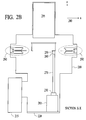
- FIG. 2B shows a cross-section through the leg stage of FIG. 2A, in the vertical plane containing X-X′, and also shows a second platform movement member, a vacuum chamber, and charged particle optics.
- FIG. 2C shows a plan view of the platform, with wafer and wafer chuck removed.
- FIG. 3A shows a diagrammatic plan view of the platform movement member, showing magnet configuration.
- FIG. 3B shows a diagrammatic cross-sectional view of the platform movement member of FIG. 3A, along A-A′, showing relative placement of magnets and coil.
- FIG. 3C shows a plan view of the stage platform, showing the drive coils and a schematic representation of the current control system.
- FIG. 3D shows a plan view of the stage platform, showing the cooling lines and a schematic representation of the cooling circuit.
- FIG. 3E is a schematic illustration of the superposition of the magnets and first coils.
- FIG. 4 shows a block diagram of a preferred embodiment of the electrical current control system.
- FIG. 5 is a diagrammatic illustration of a preferred embodiment of the stage sensors.
- FIG. 6A is a schematic representation of a raising member.
- FIG. 6B is a diagrammatic illustration of a first design of the raising actuator.
- FIG. 6C is a diagrammatic illustration of a second design of a raising actuator, shown as a side view.
- FIG. 6D is a diagrammatic illustration of a second design of a raising actuator, shown as a top view.
- FIG. 7 shows a two degrees of freedom of movement flexural joint.
- FIG. 8A is a diagrammatic plan view of an embodiment of a three degrees of freedom of movement flexural joint.
- FIG. 8B shows a diagrammatic cross-sectional view of the second flexure hinge from FIG. 8 A.
- FIG. 8C shows a diagrammatic cross-sectional view of the first flexure hinge from FIG. 8 A.
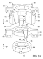
- FIG. 9A shows an exploded perspective view of a preferred embodiment of the three degrees of freedom of movement flexural joint.
- FIG. 9B shows a preferred embodiment of the three degrees of freedom of movement flexural joint with tilt of the leg axis.
- FIG. 9C shows a preferred embodiment of the three degrees of freedom of movement flexural joint with rotation about the leg axis.
- FIG. 10A shows an exploded perspective of an embodiment of a two degrees of freedom of movement flexural joint.
- FIG. 10B shows an embodiment of a two degrees of freedom of movement flexural joint with tilt of the leg axis.
- FIG. 10C shows an embodiment of a two degrees of freedom of movement flexural joint with rotation about the leg axis.
- FIG. 2A shows a perspective of a preferred embodiment of this invention; various components are not shown, for ease of illustration.
- stage 200 stage 200 , base 220 , first attachment members 230 , platform 240 , wafer chuck 242 , wafer 244 , bottom platform surface 250 , second attachment members 260 , legs 270 , platform axes 280 , raising members 285 , and platform movement members 290 are shown.
- FIG. 2B shows a cross-section through the leg stage.
- FIG. 2C shows the platform with wafer and wafer chuck removed.
- platform beams 245 platform actuator carriers 246 , carrier holes 247 , wafer chuck support 248 and leg brackets 249 are shown.
- first attachment members 230 are coupled to raising members 285 and to the bottom ends of legs 270 .
- the raising members are coupled to the base 220 .
- the legs support platform 240 and the top ends of legs 270 are coupled to bottom platform surface 250 by second attachment members 260 .
- Platform movement member 290 is coupled to the platform. In preferred embodiments the legs are substantially parallel to each other.
- frame 210 is vacuum-sealed and coupled to a laboratory floor, through base 220 . In alternate embodiments, some vibration isolation may be provided between the frame and the laboratory floor.
- Vacuum pump 215 is connected to vacuum-sealed frame 210 , allowing effective evacuation of the vacuum-sealed frame (reaching high vacuum).
- Charged particle optics 295 is mechanically coupled to the vacuum-sealed frame 210 . The charged particle optics can be used to generate and control a beam or beams of charged particles, directed onto the stage.
- the wafer chuck 242 will require a high voltage supply. Most embodiments will have a high voltage supply (not shown) external to the stage; thus requiring a high voltage connector (not shown) between the stage and supply. In the case where the frame is vacuum-sealed, the connector will need to be vacuum compatible and the high voltage supply may conveniently be placed outside the vacuum-sealed frame.
- the connector can be attached to the wafer chuck from below in such a way as to avoid contact with the legs 270 during motion and care must be taken when designing the connector to minimize the transfer of mechanical impulses and vibrations along the connector.
- FIG. 2C the construction of platform 240 is shown in detail for a particular embodiment.
- the platform actuator carriers 246 and the wafer chuck support 248 are attached to the platform beams 245 .
- the leg brackets 249 are attached to the wafer chuck support 248 ; the legs 270 may be attached to leg brackets 249 by second attachment members 260 .
- Stage 200 is a device providing a work platform positionable to high precision.
- stage 200 can provide controllable positioning of platform 240 such that a point on the platform can be positioned to within at least a micrometer relative to a reference position, such as the position of lithography optics 295 .
- platform 240 has six degrees of freedom of movement.
- the platform may translate along three axes (x, y, z) and rotate about each axis ( ⁇ x , ⁇ y , ⁇ z ).
- the stage according to this invention may be referred to equivalently as a ‘leg stage’, due to its novel legged configuration.
- the platform movement members 290 principally control movement in x, y and ⁇ z and the raising members 285 principally control movement in z, ⁇ x and ⁇ y .
- legs 270 act as supporting elements for the weight of platform 240 .
- the legs are also advantageous for electrical isolation in embodiments of the invention where there are large differences in electrical potential between elements.
- the legs may act to isolate the high voltage workpiece from other elements of stage 200 if the legs are constructed of substantially electrically insulating material.
- additional electrical isolation of the workpiece may be accomplished by constructing the platform of substantially electrically insulating material, such as alumina-based ceramic; more specifically, the platform beams 245 , platform actuator carriers 246 and wafer chuck support 248 shown in FIG. 2C may be fabricated of insulating material.
- Positioning platform movement members 290 away from the center of the platform, where the high voltage workpiece may be, is also an aspect of electrical isolation in a preferred embodiment.
- platform 240 is free to move relative to frame 210 .
- An aspect of the motion is accomplished with platform movement member 290 .
- a wafer chuck 242 which is part of platform 240 , is used to hold a wafer 244 during lithographic processing.
- alumina-based ceramic for constructing the stage platform 240 and legs 270 , is an important contribution to achieving a low-mass high precision stage; design is also optimized to reduce weight, for example the alumina legs may be hollow, the alumina platform beams 245 may be ‘U’ shaped in cross-section and the alumina platform actuator carriers 246 may have carrier holes 247 .
- FIG. 2C shows such a lightweight design.
- FIGS. 3A-3E illustrate platform movement members 290 for a preferred embodiment of this invention.
- the platform movement members provide controllable planar motion of platform 240 relative to frame 210 .
- the platform movement members are comprised of four platform actuators, more specifically four electromagnetic platform actuators.
- FIG. 3A frame 210 , platform 240 , magnets 330 and magnet supports 335 are shown.
- FIG. 3B is a cross-sectional view from the plane AA′ of FIG. 3 A.
- frame 210 , platform 240 , first coil 310 , cooling channels 325 , magnets 330 , magnet supports 335 and electromagnetic platform actuator 337 are shown.
- FIGS. 3C and 3D show plan views of systems integral to the platform movement member for a preferred embodiment.
- platform 240 , current control system 340 , first coils 310 and first coil connecting cables 316 are shown.
- FIG. 3D platform 240 , cooling channels 325 and cooling system 350 are shown.
- FIG. 3E one of first coils 310 , first coil connecting cable 316 , magnets 330 , first coil leg 312 , second coil leg 314 and magnet dimension 322 are shown.
- magnets 330 are attached to magnet supports 335 , with N and S poles placed so as to form magnetic circuits according to well-known principles; this magnet configuration and magnet support together are referred to as a first magnet assembly.
- the magnet supports are attached to frame 210 .
- First coils 310 are attached to platform 240 and are electrically coupled to current control system 340 (see FIG. 3 C).
- first coils are attached to the platform, continuous and finely controllable planar (x, y) motion of the platform relative to the frame may be accomplished by precise control of the electrical currents in selected first coils. Differential control of the electrical currents supplied to the coils may also allow rotation of the platform about the z axis. It is noteworthy that different magnet assemblies and corresponding first coils may contain differently sized magnets and first coils, or carry different electrical currents. The sizes and positioning of the magnets, first coils, and the magnitude of the electrical current flowing through the first coils are determined by the force and travel requirements in a particular direction of motion.
- FIG. 3C illustrates a configuration of first coils 310 on platform 240 according to aspects of this invention.
- the configuration of first coils 310 minimizes the magnetic field strength at the center of platform 240 .
- attention to the magnetic field strength over the platform is important in embodiments where the platform is an element in a charged particle lithography system.
- stray magnetic fields can act to deflect the charged particles and may corrupt desired patterns formed by the charged particles in a resist material; it may be necessary to introduce some magnetic shielding (not shown) to keep stray magnetic field strength within acceptable limits.
- the first coils could be arranged in a mirror image configuration, such that like-sized coils face each other, rather than being diametrically opposed as in FIG. 3C; also coils could be arranged so as to minimize the moment about the center of gravity of the stage.
- the electrical resistances of first coils 310 dissipate a fraction of the electrical energy supplied to them, converting it to sensible heat.
- Cooling system 350 removes heat generated by the first coils, maintaining a desired reference temperature at the center of the platform to within better than +/ ⁇ 0.1 degrees Celsius.
- the cooling system 350 may comprise closed circuit channels for flow of coolant, a pump, and a device for regulating the temperature of the coolant. Coolant channels 325 according to an exemplary embodiment are shown in FIG. 3 D. Other cooling techniques are readily apparent to those skilled in the art.
- the current control system 340 and cooling system 350 may conveniently be placed outside the frame 210 .
- the coolant channels 325 and first coil connecting cables 316 will need to be vacuum compatible.
- the channels and cables can be attached to the wafer chuck from below in such a way as to avoid compromising the motion of legs 270 during movement of the stage. Care must be taken when designing the channels and cables to minimize the transfer of mechanical impulses and vibrations along the channels and cables.
- FIG. 3E shows the superposition of the magnets 330 and first coil 310 .
- the motive force on the coils is the Lorentz force acting on the electrons flowing in the first and second coil legs. From FIG. 3E, it is apparent that the Lorentz forces on opposing first coil legs 312 will substantially cancel each other. This is the case since the current paths in the opposing first coil legs, which are acted upon by like magnetic fields, are in opposite directions. Therefore, the range of motion of the coils relative to the magnets is determined by width 322 .
- the exemplary embodiment shown in FIG. 3E is a non-commutated motor. In applications requiring limited ranges of motion, non-commutated motors are preferred. However, in applications that require much larger ranges of motion, commutated linear electromagnetic motors, which are well-known in the art, may be used.
- the platform movement members are linear actuators
- a minimum of three such actuators will be needed to provide motion with three degrees of freedom, as discussed above.
- FIG. 4 shows a block diagram of a preferred embodiment of current control system 340 as an integrated control system for stage 200 (see FIG. 2A, FIG. 3 C and FIG. 6 B).
- current control system 340 trajectory generator 360 , conversion matrix 362 , feedforward controller 364 , feedback controller 366 , gravity compensator 368 , predictor 370 , adder and steering matrix 372 , current amplifiers 374 , stage sensors 380 and stage actuators 390 are shown.
- the stage actuators comprise platform movement member 290 and raising actuators 430 (see FIG. 2 A).
- Current control system 340 comprises a control system that receives stage position data from stage sensors 380 as input and delivers driving electrical currents for stage actuators 390 as output. The direction of information flow is indicated in FIG. 4 .
- Current control system 340 receives data input from stage sensors 380 , and converts the data into (x, y, z, ⁇ x , ⁇ y , ⁇ z ) coordinates, representing the sensed position of the stage, by conversion matrix 362 . These values are sent to gravity compensator 368 , feedback controller 366 and predictor 370 . Trajectory generator 360 specifies desired coordinates (x, y, z, ⁇ x , ⁇ y , ⁇ z ) as a function of time from stored values. These sets of values are sent to feedforward controller 364 and feedback controller 366 .
- feedforward controller 366 sets of coordinates for the actual and sensed positions are fed into feedback controller 366 , which compares the desired position with the sensed position and calculates corrective signals to adjust the position of the stage.
- Trajectory generator coordinates are input to feedforward controller 364 , which determines the platform acceleration and generates corrective signals to drive the platform to the desired coordinates.
- the feedforward controller may be adaptive, in which case input is received from the conversion matrix 362 .
- Gravity compensator 368 receives sensed coordinates and generates signals compensating for the inverted pendulum behavior of platform 240 .
- the compensator 368 can be considered as part of the feedforward controller 364 .
- Predictor 370 receives sensed coordinates and generates signals to a writing deflection system to anticipate the position of platform 240 so that lithographic patterns can be correctly placed.
- feedforward controller 364 if feedforward controller 364 is accurate, then feedback controller 366 will generate null corrective signals. Otherwise, corrective control signals are combined and signals sent to current amplifiers 374 are generated by adder and steering matrix 372 .
- the current amplifiers generate currents proportional to the control signals for driving stage actuators 390 . It is noteworthy that, since the process of position sensing takes time, there is a predictable error between the actual position of platform 240 and its sensed position at any time. This error is to overcome by predictor 370 anticipating the position of the platform 240 . Also noteworthy is that current control (as opposed to voltage control) of the stage actuators in particular embodiments may provide vibration isolation for the stage.
- FIG. 5 shows a preferred embodiment of stage sensors 380 .
- laser interferometers 382 , laser beams 384 , reflective side surfaces 385 , reflective top surface 386 , platform center 388 , and laser triangulators 383 are shown.
- Platform center 388 where a wafer may be placed, is not reflective.
- reflective top and side surfaces 386 and 385 are formed of one piece of material such as quartz or ZerodurTM glass and are integral to platform 240 and all interferometers 382 and triangulators 383 are attached to a common support structure (not shown).
- the support structure is rigidly attached to the charged particle optics (see 295 in FIG. 2 B).
- the one piece of material forming 385 and 386 is relieved on the backside in order to reduce the weight of the stage.
- laser interferometers 382 generate laser beams 384 , which are reflected off the reflective side surfaces 385 of wafer chuck 242 (see FIG. 2 A).
- the reflected laser beam generates an interference pattern upon combination with the incident beam, which allows changes in the position of the platform 240 to be accurately determined.
- Laser triangulators 383 provide a measure of the absolute distance between the triangulator and the reflective top surface 386 of platform 240 .
- the platform position is determined relative to the support structure to which all of the interferometers and triangulators are attached, and hence to the charged particle optics.
- platform 240 is attached to base 220 by legs 270 and the base is fixed to frame 210 .
- stage 200 incorporates platform-raising members.
- differential actuation of the platform raising members may result in rotations of the platform about the x and y platform axes 280 .
- FIG. 6A is a schematic of an embodiment of a raising member.
- one of legs 270 , base 220 , first attachment member 230 , raising member 285 , support element 410 , damping element 420 , and raising actuator 430 are shown.
- raising member 285 , support element 410 , damping element 420 , and raising actuator 430 are attached to the base and the attachment member.
- the base is coupled to the laboratory floor (not shown).
- support element 410 provides a supporting force that is dependent on the separation between first attachment member 230 and base 220 .
- a force provided by the support element may enhance the control performance of the raising actuator by reducing the load that the raising actuator is required to carry.
- Damping element 420 provides a force in opposition to relative motions of the attachment member and base proportional to a time rate of change of their relative positions.
- the support element and the damping element are passive.
- Raising actuator 430 is an active and controllable element in combination with a computer control system (not shown).
- FIG. 6A shows the case where motion is allowed in the z direction and constrained in all other directions. When the raising members are constrained to move linearly, then there will need to be at least 3 legs, with one such raising member attached to each leg, in order to give motion with three degrees of freedom, as described above.
- support element 410 may provide a supporting force that is independent of the separation between first attachment member 230 and base 220 (a constant force support).
- the support element and damping element may also be a single element such as a visco-elastic beam.
- the support element and damping element are a single element comprising elastic structures loaded to a degree approaching a point of elastic stability (e.g. a buckled column), as taught in U.S. Pat. No. 5,310,157.
- a low structural stiffness in this preferred embodiment may also be advantageous with respect to isolation of platform 240 from vibration.
- Alternative embodiments may consist simply of a raising actuator, a support element and raising actuator in parallel, or a damping element and a raising actuator in parallel.
- FIG. 6B shows an embodiment of the raising actuator where the raising actuator is an electromagnetic raising actuator.
- the raising actuator is an electromagnetic raising actuator.
- one of legs 270 , base 220 , first attachment member 230 , raising actuator 430 , second magnet support 440 , second magnets 450 , second coil 460 , electrical cables 317 and current control system 340 are shown.
- raising actuator 430 is attached to the base 220 and first attachment member 230 .
- base 220 may be coupled to the laboratory floor (not shown).
- Second magnets 450 are attached to second magnet support 440 , with N and S poles placed so as to form a magnetic circuit according to well known principles; this magnet configuration and magnet support together are referred to as a first magnet assembly.
- the magnet support 440 is attached to first attachment member 230 .
- Second coil 460 is attached to the base and is electrically coupled by electrical cables 317 to current control system 340 . According to well-known principles described above, the electrical currents in the coil result in a Lorentz force being exerted on the attachment member by the magnetic field.
- FIGS. 6C and 6D show another embodiment of raising member 285 .
- the raising actuator is a voice coil actuator.
- base 220 voice coil magnet 510 , voice coil 520 , shaft 530 , thin beam 540 , rigid support 550 , electrical cables 317 and current control system 340 are shown.
- th e raising actuator is attached to base 220 and comprises voice coil magnet 510 and voice coil 520 .
- the voice coil is attached to shaft 530 .
- Shaft 530 is coupled to first attachment member 230 (not shown).
- Thin beams 540 are attached to a rigid support 550 , which is attached to the base. The shaft 530 passes through thin beams 540 , but is not fixed to them.
- voice coil 520 moves in the z direction when an electric current flows through it.
- the current passing through coil 520 is controlled by current control system 340 in a manner similar to that described above. Movement of the shaft is constrained in all but the z direction by flexible thin beams 540 and rigid support 550 .
- a sp ring (not shown) may be incorporated between the voice coil magnet and the thin beams, the spring axis coaxial with shaft 530 .
- a preferred embodiment of the raising member is a Nano-kTM vibration isolator model no. SP1014 and serial numbers 317, 318 and 319 fabricated by Minus k Technology, Inc., which is fabricated using the designs and teaching in U.S. Pat. Nos. 5,178,357 5,310,157 5,370,352 5,390,892 5,549,270 5,669,594 5,794,909 and 5,833,204 incorporated by reference herein, combined in parallel with a BEI Electronics moving coil actuator model no. LA25-42-000A, which is fabricated using the designs and teaching in U.S. Pat. No. 5,345,206 incorporated by reference herein.
- This preferred embodiment of the raising member is a very low spring constant support providing horizontal guidance, which also has a very low natural frequency of motion in the vertical direction, hence providing good vibration isolation.
- This preferred embodiment of the raising member also has an adjustable spring rate for vertical motion, allowing the natural frequency of the stage to be minimized under varying operating conditions.
- first attachment members 230 and second attachment members 260 may have either two or three degrees of freedom of movement.
- the attachment members and second attachment members are flexural joints. Flexural joints are well-known in the art to be capable of smooth, continuous and highly repeatable motion.
- FIG. 7 shows a preferred embodiment of a two degrees of freedom of movement flexural joint.
- the flexural joint shown in FIG. 7 is suitable as a first attachment member 230 or second attachment member 260 .
- first joint element 610 , second joint element 620 , third joint element 630 , first flexure strip 640 , second flexure strip 650 , first flex axis 660 , second flex axis 670 , flexure strip fastener holes 680 and notches 685 are shown.
- flexure strips 640 and 650 are held in place with fasteners (not shown) inserted in holes 680 .
- the notches 685 run parallel to the grooves into which the flexure strips are inserted; the fasteners apply pressure to the walls of the notches 685 , thereby holding the flexures in place in their grooves with the force distributed over the area of the flexure in contact with the wall of the groove.
- First joint element 610 and second joint element 620 are coupled by first flexure strip 640 , defining first flex axis 660 .
- second joint element 620 and third joint element 630 are coupled by second flexure strip 650 , defining second flex axis 670 .
- the first and second flex axes are axes about which hinge-like motion of the joint elements and connecting flex strips may occur. In a preferred embodiment the first and second flex axes are orthogonal.
- the first joint element is rigidly affixed to bottom platform surface 650 and third joint element 630 is rigidly affixed to one of legs 270 .
- the first flexure strips and second flexure strips may have a thickness of about 0.010 inches and be made of spring steel, or beryllium/copper alloy, or ASTM grade 304 stainless steel.
- first attachment members 230 carry a thrusting force.
- First attachment members 230 may also have three degrees of freedom of movement.
- a two degrees of freedom of movement flexural bearing such as that illustrated in FIG. 7 may not only lack a desired degree of freedom of movement, but also may be inadequate as a thrust bearing since the flexural joint is prone to distortion or buckling.
- first flexure strip 640 and second flexure strip 650 may be made stiff and short. This may allow the joint to perform acceptably under compression.
- FIG. 8A shows a diagrammatic plan view of an embodiment of a three degrees of freedom of movement flexural joint.
- three degree of freedom of movement flexural joint 700 first joint element 710 , second joint element 720 , third joint element 730 , second flexures 740 , first flexures 750 , second flex axis 760 , first flex axis 770 , third flex axis 780 , and fasteners 790 are shown.
- the first and second flex axes are axes about which hinge-like motion of the joint elements and associated flexures may occur; rotation about the third flex axis is due to twisting of either the first, second or first and second flexures.
- first joint element 710 and third joint element 730 are coupled by second flexures 740 .
- third joint element 730 and second joint element 720 are coupled by first flexures 750 .
- the three degrees of freedom of movement flexural joint according to this invention comprises only two flexure hinges.
- the three degree-of-freedom of movement flexural joint may be fastened to base 220 with fasteners 790 and rigidly affixed to one of legs 270 (see FIG. 2 A).
- the first joint element 710 may be spaced from the base to which it is attached in order to allow hinging motion of the joint (not shown).
- FIG. 8 B and FIG. 8C show cross-sectional views of one of second flexure 740 and first flexure 750 , respectively.
- first joint element 710 , second joint element 720 , third joint element 730 , second flexure strip 705 , first flexure strip 715 , fasteners 725 , caps 735 and one of legs 270 are shown.
- first joint element 710 and third joint element 730 are coupled by second flexure strip 705 .
- the second flexure strip is attached to the first and third joint elements by strip fasteners 725 , forming second flexure 740 .
- the cap 735 is used to spread the force from the fasteners evenly over the end of the flexure.
- FIG. 8C shows second joint element 720 and third joint element 730 coupled by first flexure strip 715 .
- the first flexure strip is attached to the second and third joint elements by strip fasteners 725 , forming first flexure 750 .
- the cap 735 is used to spread the force from the fasteners evenly over the end of the flexure. It can be appreciated from FIG. 8 B and FIG.
- the second flexure strips 705 and first flexure strips 715 undergo tensile stresses when three degrees of freedom of movement flexural joint 700 transmits thrust to leg 270 from raising member 285 attached to first joint element 710 . It is noteworthy in FIG. 8 B and FIG. 8C that the lengths, stiffness and other characteristics of the first and second flexure strips may be different within a particular embodiment.
- the flexure strips have a thickness of about 0.010 inches and may be made of spring steel, or beryllium/copper alloy, or ASTM grade 304 stainless steel.
- FIG. 9A shows an exploded perspective view of a preferred embodiment of the three degrees of freedom of movement flexural joint.
- first joint element 810 fastener clearance holes 812 , first flexure strip attachment surfaces 814 , first load bearing surface 816 , first direction 818 , second joint element 820 , second flexure attachment surfaces 824 , second load bearing surface 826 , second direction 828 , third joint element 830 , upper third flexure attachment surfaces 833 and lower third flexure attachment surfaces 835 are shown. Flexure strips and fastening means are omitted from FIG. 9A for the sake of clarity.
- first joint element 810 is coupled to raising member 285 (see FIG. 2 A).
- Second joint element 820 is coupled to one of legs 270 and also to third joint element 830 by two first flexure strips.
- the third joint element 830 is coupled by two second flexure strips to the first joint element 810 .
- the leg 270 coupled to the second joint element 820 passes through the centers of each of the joint elements. All flexure strips are secured on flexure strip attachment surfaces 814 , 824 , 833 and 835 .
- the first load bearing surface 816 is the bottom surface of first joint element 810 ; the load bearing surface contacts raising member 285 in a typical embodiment.
- the first direction 818 is the direction normal to the first load bearing surface.
- the second load bearing surface 826 is the recessed surface of second joint element 820 , upon which leg 270 sits in a typical embodiment.
- the second direction 828 is the direction normal to the second load bearing surface. The second direction is opposite to the first direction.
- FIG. 9B shows a preferred embodiment of the three degrees of freedom of movement flexural joint with tilt of the leg axis.
- first joint element 810 , second joint element 820 , third joint element 830 , first flexure strip attachment surface 814 , caps 815 , fasteners 817 , first flexure strips 822 , second flexure strip attachment surface 824 , upper third flexure attachment surface 833 , lower third flexure attachment surface 835 and leg axis 865 are shown.
- Leg 270 and second flexure strips 834 along with their caps and fasteners, are omitted for the sake of clarity.
- first flexure strip 822 is fastened on second flexure strip attachment surface 824 and upper third flexure attachment surface 833 by caps 815 and fasteners 817 .
- second and third joint elements are connected by two first flexure strips, diametrically opposed (see FIG. 9 A); only one of the first flexure strips can be seen in FIG. 9 B.
- FIG. 9B illustrates a degree of freedom of movement of the joint.
- first flexure strips 822 bend, second joint element 820 tilts. Note that this motion results in movement of leg axis 865 as shown.
- second degree of freedom of movement is due to bending of the second flexure strips (not shown).
- FIG. 9C shows a preferred embodiment of the three degrees of freedom of movement flexural joint with rotation about the leg axis 865 .
- first joint element 810 , second joint element 820 , third joint element 830 , fastener clearance holes 812 , first flexure strip attachment surface 814 , caps 815 , fasteners 817 , second flexure attachment surface 824 , upper third flexure attachment surface 833 , second flexure strips 834 , lower third flexure strip attachment surface 835 and leg axis 865 are shown.
- Leg 270 and first flexure strips 824 along with their caps and fasteners, are omitted for the sake of clarity. Elements shown in FIG. 9C are as in FIGS. 9A and 9B.
- first and third joint elements are connected as described above for FIG. 9 A.
- second flexure strip 834 is fastened on first flexure strip attachment surface 814 and lower third flexure attachment surface 835 by caps 815 and fasteners 817 .
- the first and third joint elements are connected by two second flexure strips, diametrically opposed (see FIG. 9 A); only one of the second flexure strips can be seen in FIG. 9 C.
- FIG. 9C illustrates a third degree of freedom of movement of the joint.
- second flexure strips 834 bend and twist, for example as a reaction to a torque about leg axis 865 , there is rotational motion of second joint element 820 about leg axis 865 .
- rotational motion of second joint element 820 about leg axis 865 .
- the joint has three degrees of freedom of movement. It is noteworthy in the above that stiffness of the joint may be changed by altering the lengths or material properties of the flexure strips. Note also that the rotational movement of the joint will occur by twisting and bending of both pairs of flex strips; although, the relative amount of twisting and bending will depend on the lengths and stiffnesses of the two pairs of flexure strips. In the preferred embodiment most of the twisting occurs in the longer second flexure strips (both sets of strips having the same stiffness).
- FIGS. 9A-9C show a preferred embodiment of the three degrees of freedom of movement flexural joint.
- the joint elements in this preferred embodiment are coaxial, but not concentric. This contributes to freedom of rotation about the leg axis by allowing for longer flexure strips.
- the preferred embodiment shown in FIGS. 9A-9C may be lighter and more compact than the embodiment shown in FIG. 8A, where the joint elements are both concentric and coaxial.
- FIGS. 9A-9C The general design concept used for the three degrees of freedom of motion joint shown in FIGS. 9A-9C can be simplified to give a two degrees of freedom of motion joint; this two degrees of freedom of motion joint is shown in FIGS. 10A-10C. This joint can be used where only two degrees of freedom of motion are required.
- FIG. 10A shows an exploded perspective view of an embodiment of the two degrees of freedom of movement flexural joint.
- first joint element 810 fastener clearance holes 812 , first flexure strip attachment surfaces 814 , first load bearing surface 816 , first direction 818 , second joint element 820 , second flexure attachment surfaces 824 , second load bearing surface 826 and second direction 828 , are shown. All flexure strips are secured on flexure strip attachment surfaces 814 and 824 . (Flexure strips and fastening means are omitted from FIG. 10A for the sake of clarity.)
- the first load bearing surface 816 is the bottom surface of first joint element 810 .
- the first direction 818 is the direction normal to the first load bearing surface.
- the second load bearing surface 826 is the recessed surface of second joint element 820 .
- the second direction 828 is the direction normal to the second load bearing surface.
- the second direction is opposite to the first direction.
- FIG. 10B shows an embodiment of the two degrees of freedom of movement flexural joint with tilt of the leg axis.
- first joint element 810 second joint element 820 , first flexure strip attachment surface 814 , caps 815 , fasteners 817 , first flexure strips 822 , second flexure strip attachment surface 824 and axis 865 are shown.
- first flexure strips 822 are fastened on second flexure strip attachment surfaces 824 and first flexure strip attachment surfaces 814 by caps 815 and fasteners 817 .
- first and second joint elements are connected by two first flexure strips, diametrically opposed (see FIG. 10 A); only one of the first flexure strips can be seen in FIG. 10 B.
- FIG. 10B illustrates a degree of freedom of movement of the joint.
- first flexure strips 822 bend, second joint element 820 tilts. Note that this motion results in movement of axis 865 as shown. (Note that due to the nature of flexure strip distortion under load, there may be some displacement of one joint element with respect to the next in addition to the tilt described above.)
- FIG. 10C shows an embodiment of the two degrees of freedom of movement flexural joint with rotation about the axis 865 .
- first joint element 810 second joint element 820 , fastener clearance holes 812 , first flexure strip attachment surfaces 814 , caps 815 , fasteners 817 , second flexure attachment surfaces 824 , first flexure strips 822 and axis 865 are shown.
- Elements shown in FIG. 10C are as in FIG. 10 B.
- FIG. 10C illustrates a second degree of freedom of movement of the joint.
- first flexure strips 822 bend and twist, for example as a reaction to a torque about axis 865 , there is rotational motion of second joint element 820 about axis 1865 .
- first and second joint elements are connected by two first flexure strips, diametrically opposed (see FIG. 10 A); only one of the first flexure strips can be seen in FIG. 10 C.
- the joint has two degrees of freedom of movement. It is noteworthy in the above that stiffness of the joint may be changed by altering the length or material properties of the flexure strips.
- FIG. 2B shows a charged particle beam lithography system which is comprised of an embodiment of the present invention coupled with a vacuum system (vacuum-sealed frame 210 and vacuum pump 215 ) and a charged particle beam generator (charged particle optics 295 ).
- the charged particles could be electrons in a preferred embodiment or ions in other embodiments.
- the vacuum system maintains a gas density within the vacuumsealed frame that allows a charged particle beam to propagate without significant charged particle scattering.
- the charged particle beam lithography system generates and controls at least one charged particle beam for writing patterns on a semiconductor wafer as well as controlling the position of the at least one charged particle beam relative to the wafer.
- An aspect of positioning of the at least one charged particle beam relative to the wafer includes articulating elements of stage 200 according to this invention. Note that the stage of this invention is particularly well suited to a multiple column, multiple electron beam lithography system (each column having multiple electron beams), where columns are distributed over the area of the wafer, allowing lithography with only minimal movement of the stage.
- the top surface of the platform should be capable of accommodating a semiconductor wafer with a diameter of at least 100 mm, and preferably a diameter of 300 mm.
- a low-mass high precision stage capable of holding a 300 mm wafer weighs less than 100 lbs. This is achieved by optimizing the engineering design and using lightweight materials; the use of alumina-based ceramic for the platform 240 and legs 270 and relieving the backside of the reflective top ( 386 ) and side surfaces ( 385 ) of the platform are described above.
- Preferred embodiments of the stage as described above are operated with the wafer at 50 kV relative to the frame, and could be operated at 120 kV or higher.
Abstract
Description
Claims (4)
Priority Applications (2)
| Application Number | Priority Date | Filing Date | Title |
|---|---|---|---|
| US09/543,283 US6471435B1 (en) | 1999-11-05 | 2000-04-05 | Flexural joint |
| US10/059,048 US6872958B2 (en) | 1999-11-05 | 2002-01-28 | Platform positioning system |
Applications Claiming Priority (2)
| Application Number | Priority Date | Filing Date | Title |
|---|---|---|---|
| US16384699P | 1999-11-05 | 1999-11-05 | |
| US09/543,283 US6471435B1 (en) | 1999-11-05 | 2000-04-05 | Flexural joint |
Related Child Applications (2)
| Application Number | Title | Priority Date | Filing Date |
|---|---|---|---|
| US09/543,265 Continuation US6355994B1 (en) | 1999-11-05 | 2000-04-05 | Precision stage |
| US10/059,048 Continuation US6872958B2 (en) | 1999-11-05 | 2002-01-28 | Platform positioning system |
Publications (1)
| Publication Number | Publication Date |
|---|---|
| US6471435B1 true US6471435B1 (en) | 2002-10-29 |
Family
ID=26859996
Family Applications (1)
| Application Number | Title | Priority Date | Filing Date |
|---|---|---|---|
| US09/543,283 Expired - Fee Related US6471435B1 (en) | 1999-11-05 | 2000-04-05 | Flexural joint |
Country Status (1)
| Country | Link |
|---|---|
| US (1) | US6471435B1 (en) |
Cited By (9)
| Publication number | Priority date | Publication date | Assignee | Title |
|---|---|---|---|---|
| US20030125350A1 (en) * | 1999-02-08 | 2003-07-03 | Hassan Ian F. | Combination of formoterol and a tiotropium salt |
| US6666611B2 (en) * | 2000-08-18 | 2003-12-23 | Nikon Corporation | Three degree of freedom joint |
| EP1457826A1 (en) * | 2003-03-11 | 2004-09-15 | ASML Netherlands B.V. | Lithographic apparatus and device manufacturing method |
| EP1465013A2 (en) * | 2003-03-11 | 2004-10-06 | ASML Netherlands B.V. | Lithographic apparatus and device manufacturing method |
| WO2005111726A2 (en) * | 2004-05-14 | 2005-11-24 | Koninklijke Philips Electronics N.V. | A vibration damper or isolator |
| US20060102825A1 (en) * | 2004-11-12 | 2006-05-18 | Harless Richard I | Flexure elastomer antenna isolation system |
| EP1965258A1 (en) | 2007-03-01 | 2008-09-03 | ASML Netherlands BV | Stage system and lithographic apparatus comprising such stage system |
| US20130218304A1 (en) * | 2011-08-16 | 2013-08-22 | Samsung Electronics Co., Ltd. | Ultra-precision position control device and method for determining position and attitude information associated with a 6-degree-of-freedom stage thereof |
| US11566662B2 (en) * | 2019-10-25 | 2023-01-31 | Raytheon Company | Multi-axis flexure |
Citations (20)
| Publication number | Priority date | Publication date | Assignee | Title |
|---|---|---|---|---|
| US3469417A (en) * | 1967-12-07 | 1969-09-30 | John Russell Wakelin | Torque transmitting coupling |
| US3811172A (en) | 1970-04-15 | 1974-05-21 | Singer Co | Method of manufacturing flexure hinge assembly |
| US3943778A (en) | 1974-07-01 | 1976-03-16 | Litton Systems, Inc. | Multigimbal flexure universal joint |
| US4033144A (en) * | 1976-02-18 | 1977-07-05 | Allen Clifford H | Flexible coupling |
| US4269072A (en) | 1979-02-14 | 1981-05-26 | Sperry Corporation | Flexure assembly for a dynamically tuned gyroscope |
| US4285214A (en) * | 1979-12-20 | 1981-08-25 | General Electric Company | Flexible coupling |
| US4286370A (en) | 1977-08-05 | 1981-09-01 | Incosym, Inc. | Universal joint flexure hinge suspension system, and method for manufacturing this system |
| US4380108A (en) | 1977-08-05 | 1983-04-19 | Incosym, Inc. | Universal joint flexure hinge suspension system, and method for manufacturing this system |
| US4495844A (en) * | 1980-01-17 | 1985-01-29 | Jackson Brian L | Rotary microtome drive |
| US4516958A (en) * | 1983-11-03 | 1985-05-14 | Hidden Valley Associates, Inc. | Flexible shaft coupling device |
| US4528864A (en) | 1980-05-19 | 1985-07-16 | Incosym, Inc. | Universal joint flexure hinge suspension system and method for manufacturing this system |
| US4559717A (en) | 1984-02-21 | 1985-12-24 | The United States Of America As Represented By The Secretary Of Commerce | Flexure hinge |
| US4592242A (en) | 1982-04-14 | 1986-06-03 | Bodenseewerk Geratetechnik Gmbh | Dynamically tuned gimbal suspension with flexural pivots for a two-degree-of-freedom gyro |
| US4694703A (en) | 1984-06-28 | 1987-09-22 | Lear Siegler, Inc. | Circumferentially oriented flexure suspension |
| US4834690A (en) * | 1986-01-23 | 1989-05-30 | Kokusai Gijutsu Kaihatsu Kabushiki Kaisha | Flexible coupling with bent plate body |
| US5293782A (en) * | 1990-03-19 | 1994-03-15 | Eastman Kodak Company | Process and device for driving a surface in a reciprocating motion in a plane |
| US5302044A (en) | 1991-07-09 | 1994-04-12 | Societe Nationale Industrielle Et Aerospatiale | Temporary mechanical attachment device flexible in bending and designed to fracture at a predetermined tensile load, and method of manufacturing it |
| US5392662A (en) * | 1993-09-20 | 1995-02-28 | Eastman Kodak Company | Leadscrew coupler |
| US5879098A (en) * | 1996-04-03 | 1999-03-09 | Commissariat A L'energie Atomique | Device for the tight crossing of a partition by a mobile member |
| US6059481A (en) * | 1997-02-06 | 2000-05-09 | Csem Centre Suisse D'electronique Et De Microtechnique S.A. | Device for the guidance in rectilinear translation of an object that is mobile in relation to a fixed object |
-
2000
- 2000-04-05 US US09/543,283 patent/US6471435B1/en not_active Expired - Fee Related
Patent Citations (21)
| Publication number | Priority date | Publication date | Assignee | Title |
|---|---|---|---|---|
| US3469417A (en) * | 1967-12-07 | 1969-09-30 | John Russell Wakelin | Torque transmitting coupling |
| US3811172A (en) | 1970-04-15 | 1974-05-21 | Singer Co | Method of manufacturing flexure hinge assembly |
| US3943778A (en) | 1974-07-01 | 1976-03-16 | Litton Systems, Inc. | Multigimbal flexure universal joint |
| US4033144A (en) * | 1976-02-18 | 1977-07-05 | Allen Clifford H | Flexible coupling |
| US4286370A (en) | 1977-08-05 | 1981-09-01 | Incosym, Inc. | Universal joint flexure hinge suspension system, and method for manufacturing this system |
| US4380108A (en) | 1977-08-05 | 1983-04-19 | Incosym, Inc. | Universal joint flexure hinge suspension system, and method for manufacturing this system |
| US4269072A (en) | 1979-02-14 | 1981-05-26 | Sperry Corporation | Flexure assembly for a dynamically tuned gyroscope |
| US4285214A (en) * | 1979-12-20 | 1981-08-25 | General Electric Company | Flexible coupling |
| US4495844A (en) * | 1980-01-17 | 1985-01-29 | Jackson Brian L | Rotary microtome drive |
| US4528864A (en) | 1980-05-19 | 1985-07-16 | Incosym, Inc. | Universal joint flexure hinge suspension system and method for manufacturing this system |
| US4592242A (en) | 1982-04-14 | 1986-06-03 | Bodenseewerk Geratetechnik Gmbh | Dynamically tuned gimbal suspension with flexural pivots for a two-degree-of-freedom gyro |
| US4665605A (en) | 1982-04-14 | 1987-05-19 | Bodenseewerk Geratetechnic GmbH | Method of making dynamically tuned gimbal suspension |
| US4516958A (en) * | 1983-11-03 | 1985-05-14 | Hidden Valley Associates, Inc. | Flexible shaft coupling device |
| US4559717A (en) | 1984-02-21 | 1985-12-24 | The United States Of America As Represented By The Secretary Of Commerce | Flexure hinge |
| US4694703A (en) | 1984-06-28 | 1987-09-22 | Lear Siegler, Inc. | Circumferentially oriented flexure suspension |
| US4834690A (en) * | 1986-01-23 | 1989-05-30 | Kokusai Gijutsu Kaihatsu Kabushiki Kaisha | Flexible coupling with bent plate body |
| US5293782A (en) * | 1990-03-19 | 1994-03-15 | Eastman Kodak Company | Process and device for driving a surface in a reciprocating motion in a plane |
| US5302044A (en) | 1991-07-09 | 1994-04-12 | Societe Nationale Industrielle Et Aerospatiale | Temporary mechanical attachment device flexible in bending and designed to fracture at a predetermined tensile load, and method of manufacturing it |
| US5392662A (en) * | 1993-09-20 | 1995-02-28 | Eastman Kodak Company | Leadscrew coupler |
| US5879098A (en) * | 1996-04-03 | 1999-03-09 | Commissariat A L'energie Atomique | Device for the tight crossing of a partition by a mobile member |
| US6059481A (en) * | 1997-02-06 | 2000-05-09 | Csem Centre Suisse D'electronique Et De Microtechnique S.A. | Device for the guidance in rectilinear translation of an object that is mobile in relation to a fixed object |
Non-Patent Citations (1)
| Title |
|---|
| Slocum, "Precision Machine Design", 1992, pp. 521-538, Prentice Hall, NJ, USA. |
Cited By (21)
| Publication number | Priority date | Publication date | Assignee | Title |
|---|---|---|---|---|
| US20030125350A1 (en) * | 1999-02-08 | 2003-07-03 | Hassan Ian F. | Combination of formoterol and a tiotropium salt |
| US6666611B2 (en) * | 2000-08-18 | 2003-12-23 | Nikon Corporation | Three degree of freedom joint |
| KR100631098B1 (en) * | 2003-03-11 | 2006-10-02 | 에이에스엠엘 네델란즈 비.브이. | Lithographic Apparatus and Device Manufacturing Method |
| EP1457826A1 (en) * | 2003-03-11 | 2004-09-15 | ASML Netherlands B.V. | Lithographic apparatus and device manufacturing method |
| EP1465013A2 (en) * | 2003-03-11 | 2004-10-06 | ASML Netherlands B.V. | Lithographic apparatus and device manufacturing method |
| US20040246458A1 (en) * | 2003-03-11 | 2004-12-09 | Asml Netherlands B.V. | Lithographic linear motor, lithographic apparatus, and device manufacturing method |
| EP1465013A3 (en) * | 2003-03-11 | 2006-08-09 | ASML Netherlands B.V. | Lithographic apparatus and device manufacturing method |
| US7095485B2 (en) | 2003-03-11 | 2006-08-22 | Asml Netherlands B.V. | Lithographic linear motor, lithographic apparatus, and device manufacturing method |
| WO2005111726A2 (en) * | 2004-05-14 | 2005-11-24 | Koninklijke Philips Electronics N.V. | A vibration damper or isolator |
| US20080258365A1 (en) * | 2004-05-14 | 2008-10-23 | Koninklijke Philips Electronics, N.V. | Vibration Damper for Isolator |
| WO2005111726A3 (en) * | 2004-05-14 | 2006-08-03 | Koninkl Philips Electronics Nv | A vibration damper or isolator |
| US7104515B2 (en) | 2004-11-12 | 2006-09-12 | Harris Corporation | Flexure elastomer antenna isolation system |
| US20070139292A1 (en) * | 2004-11-12 | 2007-06-21 | Harris Corporation | Flexure elastomer antenna isolation system |
| US7248228B2 (en) | 2004-11-12 | 2007-07-24 | Harris Corporation | Flexure elastomer antenna isolation system |
| US20060102825A1 (en) * | 2004-11-12 | 2006-05-18 | Harless Richard I | Flexure elastomer antenna isolation system |
| EP1965258A1 (en) | 2007-03-01 | 2008-09-03 | ASML Netherlands BV | Stage system and lithographic apparatus comprising such stage system |
| US20080212054A1 (en) * | 2007-03-01 | 2008-09-04 | Asml Netherlands B.V. | Stage system and lithographic apparatus comprising such stage system |
| US7782446B2 (en) * | 2007-03-01 | 2010-08-24 | Asml Netherlands B.V. | Stage system and lithographic apparatus comprising such stage system |
| US20130218304A1 (en) * | 2011-08-16 | 2013-08-22 | Samsung Electronics Co., Ltd. | Ultra-precision position control device and method for determining position and attitude information associated with a 6-degree-of-freedom stage thereof |
| US9069336B2 (en) * | 2011-08-16 | 2015-06-30 | Samsung Electronics Co., Ltd. | Ultra-precision position control device and method for determining position and attitude information associated with a 6-degree-of-freedom stage thereof |
| US11566662B2 (en) * | 2019-10-25 | 2023-01-31 | Raytheon Company | Multi-axis flexure |
Similar Documents
| Publication | Publication Date | Title |
|---|---|---|
| US6355994B1 (en) | Precision stage | |
| US6353271B1 (en) | Extreme-UV scanning wafer and reticle stages | |
| US7348709B2 (en) | Heavy-load nanopositioner with dual-parallel flexure design | |
| US6322060B1 (en) | Anti-vibration apparatus, exposure apparatus using the same, device manufacturing method, and anti-vibration method | |
| KR101129119B1 (en) | Apparatus for manipulation of an optical element | |
| US6822407B2 (en) | Multiple degree of freedom substrate manipulator | |
| US6777833B1 (en) | Magnetic levitation stage apparatus and method | |
| US7898204B2 (en) | High-speed substrate manipulator | |
| US6639225B2 (en) | Six-axis positioning system having a zero-magnetic-field space | |
| US6471435B1 (en) | Flexural joint | |
| JP2002313716A (en) | Lithographic method having separated dual system and method of constituting the same | |
| US6742393B2 (en) | Vibration control apparatus, vibration control method, exposure apparatus, and device manufacturing method | |
| KR20030076275A (en) | A positioning system and a stage system capable of preventing cable drag forces from acting on a stage and method of preventing cable drag forces from acting on the stage | |
| EP1262835A2 (en) | Compact stage of low mass with device for fine positioning in six degrees of freedom for microlithography | |
| CN214848581U (en) | Micropositioner and motion device | |
| Shinno et al. | Nanometer positioning of a linear motor-driven ultraprecision aerostatic table system with electrorheological fluid dampers | |
| JP2003318103A (en) | Method, system and apparatus for management of reaction load in lithography system | |
| US6597435B2 (en) | Reticle stage with reaction force cancellation | |
| EP0183125B1 (en) | Positioning system | |
| US6794660B2 (en) | Long stroke mover for a stage assembly | |
| KR20130022253A (en) | Ultra-precision moving apparatus | |
| JP2005297109A (en) | Slow motion stage | |
| US20030010935A1 (en) | Stage assembly having a follower assembly | |
| Williams et al. | Six degrees of freedom Mag-Lev stage development | |
| Mittal et al. | Multifunctional Z actuator with an adjustable built-in gravity compensator for high precision systems |
Legal Events
| Date | Code | Title | Description |
|---|---|---|---|
| AS | Assignment |
Owner name: ION DIAGNOSTICS, INC., CALIFORNIA Free format text: ASSIGNMENT OF ASSIGNORS INTEREST;ASSIGNOR:LEE, MARTIN E.;REEL/FRAME:010692/0355 Effective date: 20000405 |
|
| AS | Assignment |
Owner name: MULTIBEAM SYSTEMS, INC., CALIFORNIA Free format text: ASSIGNMENT OF ASSIGNORS INTEREST;ASSIGNOR:ION DIAGNOSTICS, INC.;REEL/FRAME:012367/0322 Effective date: 20010814 Owner name: MOTOROLA, INC., ILLINOIS Free format text: ASSIGNMENT OF ASSIGNORS INTEREST;ASSIGNOR:ION DIAGNOSTICS, INC.;REEL/FRAME:012367/0346 Effective date: 20010810 |
|
| AS | Assignment |
Owner name: FREESCALE SEMICONDUCTOR, INC., TEXAS Free format text: ASSIGNMENT OF ASSIGNORS INTEREST;ASSIGNOR:MOTOROLA, INC.;REEL/FRAME:015698/0657 Effective date: 20040404 Owner name: FREESCALE SEMICONDUCTOR, INC.,TEXAS Free format text: ASSIGNMENT OF ASSIGNORS INTEREST;ASSIGNOR:MOTOROLA, INC.;REEL/FRAME:015698/0657 Effective date: 20040404 |
|
| FEPP | Fee payment procedure |
Free format text: PAT HOLDER NO LONGER CLAIMS SMALL ENTITY STATUS, ENTITY STATUS SET TO UNDISCOUNTED (ORIGINAL EVENT CODE: STOL); ENTITY STATUS OF PATENT OWNER: LARGE ENTITY |
|
| REFU | Refund |
Free format text: REFUND - SURCHARGE FOR LATE PAYMENT, SMALL ENTITY (ORIGINAL EVENT CODE: R2554); ENTITY STATUS OF PATENT OWNER: LARGE ENTITY Free format text: REFUND - SURCHARGE, PETITION TO ACCEPT PYMT AFTER EXP, UNINTENTIONAL (ORIGINAL EVENT CODE: R2551); ENTITY STATUS OF PATENT OWNER: LARGE ENTITY |
|
| REMI | Maintenance fee reminder mailed | ||
| FPAY | Fee payment |
Year of fee payment: 4 |
|
| SULP | Surcharge for late payment | ||
| AS | Assignment |
Owner name: CITIBANK, N.A. AS COLLATERAL AGENT, NEW YORK Free format text: SECURITY AGREEMENT;ASSIGNORS:FREESCALE SEMICONDUCTOR, INC.;FREESCALE ACQUISITION CORPORATION;FREESCALE ACQUISITION HOLDINGS CORP.;AND OTHERS;REEL/FRAME:018855/0129 Effective date: 20061201 Owner name: CITIBANK, N.A. AS COLLATERAL AGENT,NEW YORK Free format text: SECURITY AGREEMENT;ASSIGNORS:FREESCALE SEMICONDUCTOR, INC.;FREESCALE ACQUISITION CORPORATION;FREESCALE ACQUISITION HOLDINGS CORP.;AND OTHERS;REEL/FRAME:018855/0129 Effective date: 20061201 |
|
| AS | Assignment |
Owner name: CITIBANK, N.A., AS COLLATERAL AGENT,NEW YORK Free format text: SECURITY AGREEMENT;ASSIGNOR:FREESCALE SEMICONDUCTOR, INC.;REEL/FRAME:024397/0001 Effective date: 20100413 Owner name: CITIBANK, N.A., AS COLLATERAL AGENT, NEW YORK Free format text: SECURITY AGREEMENT;ASSIGNOR:FREESCALE SEMICONDUCTOR, INC.;REEL/FRAME:024397/0001 Effective date: 20100413 |
|
| REMI | Maintenance fee reminder mailed | ||
| LAPS | Lapse for failure to pay maintenance fees | ||
| STCH | Information on status: patent discontinuation |
Free format text: PATENT EXPIRED DUE TO NONPAYMENT OF MAINTENANCE FEES UNDER 37 CFR 1.362 |
|
| FP | Lapsed due to failure to pay maintenance fee |
Effective date: 20101029 |
|
| AS | Assignment |
Owner name: FREESCALE SEMICONDUCTOR, INC., TEXAS Free format text: PATENT RELEASE;ASSIGNOR:CITIBANK, N.A., AS COLLATERAL AGENT;REEL/FRAME:037354/0225 Effective date: 20151207 Owner name: FREESCALE SEMICONDUCTOR, INC., TEXAS Free format text: PATENT RELEASE;ASSIGNOR:CITIBANK, N.A., AS COLLATERAL AGENT;REEL/FRAME:037356/0143 Effective date: 20151207 Owner name: FREESCALE SEMICONDUCTOR, INC., TEXAS Free format text: PATENT RELEASE;ASSIGNOR:CITIBANK, N.A., AS COLLATERAL AGENT;REEL/FRAME:037356/0553 Effective date: 20151207 |