US6480098B2 - Remote vehicle control system including common carrier paging receiver and related methods - Google Patents
Remote vehicle control system including common carrier paging receiver and related methods Download PDFInfo
- Publication number
- US6480098B2 US6480098B2 US09/039,204 US3920498A US6480098B2 US 6480098 B2 US6480098 B2 US 6480098B2 US 3920498 A US3920498 A US 3920498A US 6480098 B2 US6480098 B2 US 6480098B2
- Authority
- US
- United States
- Prior art keywords
- vehicle
- wireless
- control system
- controller
- remote control
- Prior art date
- Legal status (The legal status is an assumption and is not a legal conclusion. Google has not performed a legal analysis and makes no representation as to the accuracy of the status listed.)
- Expired - Fee Related
Links
Images
Classifications
-
- B—PERFORMING OPERATIONS; TRANSPORTING
- B60—VEHICLES IN GENERAL
- B60R—VEHICLES, VEHICLE FITTINGS, OR VEHICLE PARTS, NOT OTHERWISE PROVIDED FOR
- B60R25/00—Fittings or systems for preventing or indicating unauthorised use or theft of vehicles
- B60R25/20—Means to switch the anti-theft system on or off
- B60R25/2018—Central base unlocks or authorises unlocking
-
- B—PERFORMING OPERATIONS; TRANSPORTING
- B60—VEHICLES IN GENERAL
- B60R—VEHICLES, VEHICLE FITTINGS, OR VEHICLE PARTS, NOT OTHERWISE PROVIDED FOR
- B60R25/00—Fittings or systems for preventing or indicating unauthorised use or theft of vehicles
- B60R25/01—Fittings or systems for preventing or indicating unauthorised use or theft of vehicles operating on vehicle systems or fittings, e.g. on doors, seats or windscreens
- B60R25/04—Fittings or systems for preventing or indicating unauthorised use or theft of vehicles operating on vehicle systems or fittings, e.g. on doors, seats or windscreens operating on the propulsion system, e.g. engine or drive motor
-
- B—PERFORMING OPERATIONS; TRANSPORTING
- B60—VEHICLES IN GENERAL
- B60R—VEHICLES, VEHICLE FITTINGS, OR VEHICLE PARTS, NOT OTHERWISE PROVIDED FOR
- B60R25/00—Fittings or systems for preventing or indicating unauthorised use or theft of vehicles
- B60R25/10—Fittings or systems for preventing or indicating unauthorised use or theft of vehicles actuating a signalling device
- B60R25/1003—Alarm systems characterised by arm or disarm features
-
- B—PERFORMING OPERATIONS; TRANSPORTING
- B60—VEHICLES IN GENERAL
- B60R—VEHICLES, VEHICLE FITTINGS, OR VEHICLE PARTS, NOT OTHERWISE PROVIDED FOR
- B60R25/00—Fittings or systems for preventing or indicating unauthorised use or theft of vehicles
- B60R25/20—Means to switch the anti-theft system on or off
- B60R25/24—Means to switch the anti-theft system on or off using electronic identifiers containing a code not memorised by the user
-
- B—PERFORMING OPERATIONS; TRANSPORTING
- B60—VEHICLES IN GENERAL
- B60R—VEHICLES, VEHICLE FITTINGS, OR VEHICLE PARTS, NOT OTHERWISE PROVIDED FOR
- B60R2325/00—Indexing scheme relating to vehicle anti-theft devices
- B60R2325/20—Communication devices for vehicle anti-theft devices
- B60R2325/202—Personal digital assistant [PDA]
Definitions
- the present invention relates to the field of vehicle control systems and related methods, and more particularly, to a vehicle remote control system and method.
- a typical automobile security system includes a central processor or controller connected to a plurality of vehicle sensors.
- the sensors may detect opening of the trunk, hood, doors, windows, and also movement of the vehicle or movement within the vehicle.
- Ultrasonic and microwave motion detectors, vibration sensors, sound discriminators, differential pressure sensors, and switches may be used as sensors.
- radar sensors may be used to monitor the area proximate the vehicle.
- the controller typically operates to give an alarm indication in the event of triggering of a vehicle sensor.
- the alarm indication may typically be a flashing of the lights and/or the sounding of the vehicle horn or a siren.
- the vehicle fuel supply and/or ignition power may be selectively disabled based upon an alarm condition.
- a number of patents disclose radio transmitters in a vehicle security system for alerting a user away from the vehicle via a dedicated receiver carried by the vehicle owner.
- U.S. Pat. No. 4,924,206 to Ayers discloses such a conventional system.
- U.S. Pat. No. 5,027,104 to Reid discloses a vehicle security system including vehicle mounted cameras that may alert the vehicle owner via a dedicated receiver, and while also sending a video signal to a second receiver location.
- U.S. Pat. No. 5,216,407 to Hwang discloses a vehicle security system including a paging system for providing an output to send a warning signal to the vehicle owner's pager or portable phone.
- U.S. Pat. No. 5,276,728 to Pagliaroli et al. discloses a vehicle security system wherein the user carries a portable receiver, and can disable the vehicle by dialing an appropriate code via a cellular telephone.
- U.S. Pat. No. 5,335,264 to Namekawa discloses a vehicle security system including a handheld unit which, in turn, includes a transmitter and receiver.
- the remote receiver can receive an alarm signal from the vehicle, and a cellular telephone within the vehicle can be used to collect sounds from within the vehicle.
- the Namekawa patent, U.S. Pat. No. 4,905,271 also discloses a vehicle security system wherein the cellular telephone is turned on responsive to an alarm and which enables the driver to determine the state of the security system by calling the mobile telephone system before running to the car.
- the CREATALINKTM system includes a paging receiver operating in the 929 to 932 MHZ paging band and which also provides a number of user programmable outputs. More particularly, the user may dial a telephone number to remotely unlock and lock power doors, start a vehicle engine, disable a vehicle engine and engage an alarm indication, for example.
- a vehicle remote control system including a slightly modified remote transmitter coupled to the paging receiver to communicate with the system controller. Accordingly, harnesses need not be custom fabricated and existing wiring need not be disturbed to the controller, such as for a retrofit installation. For a new complete system installation, the transmitter providing the link from the paging receiver to the controller permits the paging receiver to be located in spaced relation from the controller, such as to improve reception to the paging receiver.
- the remote vehicle control system preferably includes a plurality of transmitters comprising at least one first transmitter for being carried by a user, a first receiver positioned at the vehicle for receiving signals from the plurality of transmitters, and the controller positioned at the vehicle and being connected to wiring at the vehicle and to the first receiver for controlling at least one vehicle function responsive to the plurality of transmitters.
- the system also preferably includes the second or paging receiver positioned at the vehicle for receiving signals via a common carrier paging network and for generating output control signals responsive to received signals from the common carrier paging network.
- the plurality of transmitters preferably further includes a second transmitter positioned at the vehicle and connected to the second receiver for communicating output control signals to the controller and via the first receiver.
- a relatively inexpensive remote transmitter can be adapted to interface the paging receiver to the vehicle control system.
- the paging receiver may include a plurality of power inputs for connection to vehicle power.
- the second transmitter may also include power inputs connected in parallel with the power inputs of the second receiver.
- the output signals from the second receiver are preferably communicated to the controller only via the second transmitter and the first receiver.
- the only common electrical connections are the power supply connections of the vehicle and no special harnesses or other wiring is needed to install the paging receiver and have it operate in conjunction with the controller.
- the controller is switchable between armed and disarmed modes responsive to the plurality of transmitters.
- An alarm indicator may also be connected to the controller for sounding an alarm at the vehicle responsive to the plurality of transmitters and/or to one or more vehicle security sensors.
- the controller may comprise door lock control means for controlling locking and unlocking of vehicle doors responsive to the plurality of transmitters. Accordingly, the user could have the remote control system unlock the vehicle doors by calling an appropriate common carrier pager service telephone number, entering a unique personal identification number, and entering a door unlock command. Such a feature would be invaluable if the user locked the vehicle keys in the vehicle, for example.
- the controller may also include engine disabling means for disabling the vehicle engine responsive to the plurality of transmitters. Accordingly, should the vehicle be stolen, the user may also dial into the common carrier paging service and activate a command to disable the engine.
- the second transmitter preferably comprises a plurality of inputs for receiving respective pulsed input signals. Accordingly, the second receiver also preferably comprises means for generating a plurality of pulsed output signals to the inputs of the second transmitter.
- At least one wiring harness may be connected at one end to the controller for interfacing the controller to wiring at the vehicle.
- two-way paging could also be implemented if it was desired to enable a user to call his vehicle and obtain certain status information.
- a method aspect of the invention is for retrofitting a paging remote control system to an existing vehicle control system 5 .
- the existing vehicle control system is preferably of a type comprising at least one first transmitter for being carried by a user, a first receiver positioned at the vehicle for receiving signals from the plurality of transmitters, and a controller positioned at the vehicle and being connected to wiring at the vehicle and to the first receiver for controlling at least one vehicle function responsive to the at least one transmitter.
- the method preferably comprises the steps of: positioning a second receiver at the vehicle for receiving signals via a common carrier paging network and for generating output control signals responsive to received signals from the common carrier paging network; and positioning a second transmitter at the vehicle and connecting the second transmitter to the second receiver for communicating output control signals therefrom to the controller and via the first receiver.
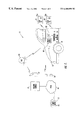
- FIG. 1 is a schematic diagram of the vehicle function control system in accordance with the present invention.
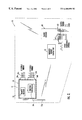
- FIG. 2 is a more detailed schematic block diagram of the vehicle mounted components as shown in FIG. 1 .
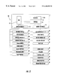
- FIG. 3 is a more detailed schematic block diagram of a security system controller of the system in accordance with the present invention.
- the system 5 includes a transmitter 53 coupled to the paging receiver 60 to communicate with the system controller/receiver 10 .
- the illustrated remote vehicle control system 5 includes a plurality of transmitters 51 - 53 of which two transmitters 51 , 52 are illustratively of the conventional handheld type for being carried by a user as will be readily appreciated by those skilled in the art.
- the third transmitter 53 is a modified version of a conventional remote transmitter as will be readily appreciated by those of skill in the art.
- the handheld transmitter 51 , 52 may be powered by respective batteries 51 a , 52 b , while the transmitter 53 connected to the paging receiver 60 is powered from the vehicle.
- a relatively inexpensive remote transmitter 53 can be adapted to interface the paging or second receiver 60 to the vehicle control system 5 .
- the paging receiver 60 may of a type available from Motorola of Boynton Beach, Florida under the mark CREATALINKTM. Of course, those of skill in the art will readily appreciate that other manufacturers' paging receivers may also be used in accordance with the present invention.
- a first receiver 13 is illustratively part of a control system module 10 positioned at the vehicle 12 for receiving signals from the plurality of transmitters 51 - 53 .
- the function controller 54 is also positioned at the vehicle 12 . Both the first receiver 13 and the function controller 54 may be contained within a common housing 11 as illustrated. Of course, in other embodiments, the receiver 13 and function controller 54 may be spaced from one another.
- the receiver 13 is also illustratively connected to an a antenna 13 a in the form of a wire as shown in FIG. 2 .
- the security system module 10 is connected to wiring at the vehicle via the illustrated connectors 56 a , 56 b and the groups of conductors 57 a , 57 b as will be readily appreciated by those skilled in the art.
- the controller 54 is also connected to the first receiver 13 for controlling at least one vehicle function responsive to the plurality of transmitters 51 - 53 .
- the connections to the vehicle wiring to install the paging receiver 60 may be minimal.
- the connections to the vehicle wiring to install the paging receiver 60 may be minimal.
- only three relatively easy to access connections for the paging receiver 60 are required: (+), ( ⁇ ), and a switched ignition source as will be appreciated by those skilled in the art.
- the connections may be made at the respective input terminals 63 of the paging receiver 60 as shown. Accordingly, harnesses need not be custom fabricated and existing wiring need not be disturbed to the control system module 10 , such as for a retrofit installation.
- the transmitter 53 providing the link from the paging receiver 60 to the function controller 54 permits the paging receiver to be located in spaced relation from the controller, such as to improve reception to the paging receiver.
- the second or paging receiver 60 positioned at the vehicle 12 is for receiving signals via a common carrier paging network and for generating output control signals responsive to received signals from the common carrier paging network.
- the common carrier paging network in the illustrated embodiment includes a central location for a paging service 71 .
- the paging service 71 may receive a telephone call from a user via a conventional telephone 72 connected to the paging service via the Public Switched Telephone Network (PSTN) 74 as will be readily appreciated by those skilled in the art.
- PSTN Public Switched Telephone Network
- the caller may be guided through a menu of voice message prompts to enter a unique personal identification code, and then through a list of optional vehicle control functions.
- the user may enter the requested information, for example, using a conventional touch tone keypad 73 .
- the paging service 71 may send out respective paging signals via one or more land-based towers 76 , and/or via a satellite ground station 77 to a satellite 78 for relay to the vehicle 12 .
- the signals to the towers or ground station may be sent directly or via the PSTN 74 as will be readily appreciated by those skilled in the art.
- the paging receiver 60 may include a plurality of power inputs for connection to vehicle power as shown in FIG. 2 .
- the transmitter 53 may also include power inputs connected in parallel with the power inputs of the paging receiver 60 .
- the output signals from the paging receiver 60 are coupled to the transmitter 53 via one or more wires 65 which, in turn, are connected to the respective output terminals 66 .
- the output terminals 66 may provide pulsed or continuous outputs, or a databus may be established between the paging receiver 60 and the transmitter 53 .
- the paging receiver 60 may have a programmable microprocessor associated therewith so that the desired signal format/protocol is impressed on the outputs 65 .
- the only common electrical connections between the control module 10 and the paging receiver 60 and transmitter 53 are the common power supply connections of the vehicle.
- the paging receiver 60 may have other outputs 67 for optional hardwired connections to certain vehicle components.
- the control module was for only remote keyless entry (RKE) the outputs 67 could be connected to a starter interrupt relay to also provide a remote security feature to the RKE system as would be readily appreciated by those skilled in the art.
- the outputs 67 may also be coupled to a garage door opening transmitter, not shown, for example.
- the function controller 34 is a security controller switchable between armed and disarmed modes responsive to the plurality of transmitters 51 - 53 .
- the control module 10 includes a central processing unit (CPU) or microprocessor 19 operating under stored program control.
- a receiver 13 and its antenna 13 a are connected to the microprocessor 19 for receiving signals from the remote transmitter 51 - 53 , which may be used to remotely arm and disarm the system, for example.
- the microprocessor 19 may also be operatively connected to an input interface 15 and an output interface 16 .
- the microprocessor 19 may be connected to an external memory or alternately or additionally have its own on-board memory 14 .
- the input interface 15 is illustratively connected to various vehicle input devices including: an ignition switch 20 ; a key in the ignition sensor 21 ; two zone sensors 22 a , 22 b ; conventional trunk hood and door pin sensors or switches 23 , 24 , and 25 , respectively; and door lock switches 28 .
- a pre-warn sensor 26 and valet switch 27 also provide inputs in the illustrated embodiment.
- other inputs are also contemplated by the present invention and are generally described herein by the term sensor.
- the output interface 16 of the controller module 10 may preferably be connected to a plurality of output devices.
- the outputs may include auxiliary relay outputs 30 , such as for window control, remote starting, or a remote alarm indication, as would be readily understood by those skilled in the art.
- a siren and/or lights 31 , and green and red light emitting diodes (LEDs) 32 , 33 for dashboard mounting are also illustratively connected to the controller 11 .
- Other outputs may be directed to a valet LED 34 , a dome light 36 , a central lock relay or lock control unit 41 , a starter kill circuit 42 , and an armed relay output 43 .
- outputs may be directed to one or more of an audible tone generator 37 , an alphanumeric display 44 , a speech message annunciator 45 , and a vibration transducer 46 , as will be readily appreciated by those skilled in the art.
- Other similar indicating devices are also contemplated by the present invention, as would also be readily understood by those skilled in the art.
- An alarm indicator in the form of a siren/lights 30 may also be connected to the controller 34 for sounding an alarm at the vehicle responsive to the plurality of transmitters 51 - 53 and/or to one or more vehicle security sensors.
- the controller 54 may comprise door lock control means for controlling locking and unlocking of vehicle doors responsive to the plurality of transmitters 51 - 53 .
- the paging receiver 60 could also be adapted to work with a conventional remote keyless entry (RKE) system as will be readily appreciated by those skilled in the art. Accordingly, the user could have the remote control system unlock the vehicle doors by calling into the common carrier pager service 71 , entering a unique personal identification number, and entering a door unlock command. Such a feature would be invaluable if the user locked the vehicle keys in the vehicle, for example.
- the controller may also include engine disabling means, such as the schematically illustrated starter kill 42 , for disabling the vehicle engine responsive to the plurality of transmitters 51 - 53 . Accordingly, should the vehicle be stolen, the user may also dial into the common carrier paging service 71 and activate a command to disable the engine. The engine could also be remotely started. Those of skill in the art will appreciate other remote control functions that could be performed.
- engine disabling means such as the schematically illustrated starter kill 42 , for disabling the vehicle engine responsive to the plurality of transmitters 51 - 53 . Accordingly, should the vehicle be stolen, the user may also dial into the common carrier paging service 71 and activate a command to disable the engine. The engine could also be remotely started. Those of skill in the art will appreciate other remote control functions that could be performed.
- a method aspect of the invention is for retrofitting a paging remote control system to an existing vehicle control system.
- the existing vehicle control system is preferably of a type comprising at least one first transmitter 51 , 52 for being carried by a user, a first receiver 13 positioned at the vehicle 12 for receiving signals from the plurality of transmitters, and a controller 54 positioned at the vehicle and being connected to wiring at the vehicle and to the first receiver for controlling at least one vehicle function responsive to the at least one transmitter.
- the method preferably comprises the steps of: positioning a second or paging receiver 60 at the vehicle for receiving signals via a common carrier paging network and for generating output control signals responsive to received signals from the common carrier paging network; and positioning a second transmitter 53 at the vehicle and connecting the second transmitter to the second receiver for communicating output control signals therefrom to the controller and via the first receiver.
- two-way paging could also be implemented if it was desired to enable a user to call his vehicle and obtain certain status information.
Abstract
Description
Claims (29)
Priority Applications (1)
| Application Number | Priority Date | Filing Date | Title |
|---|---|---|---|
| US09/039,204 US6480098B2 (en) | 1998-03-13 | 1998-03-13 | Remote vehicle control system including common carrier paging receiver and related methods |
Applications Claiming Priority (1)
| Application Number | Priority Date | Filing Date | Title |
|---|---|---|---|
| US09/039,204 US6480098B2 (en) | 1998-03-13 | 1998-03-13 | Remote vehicle control system including common carrier paging receiver and related methods |
Publications (2)
| Publication Number | Publication Date |
|---|---|
| US20020130765A1 US20020130765A1 (en) | 2002-09-19 |
| US6480098B2 true US6480098B2 (en) | 2002-11-12 |
Family
ID=21904226
Family Applications (1)
| Application Number | Title | Priority Date | Filing Date |
|---|---|---|---|
| US09/039,204 Expired - Fee Related US6480098B2 (en) | 1998-03-13 | 1998-03-13 | Remote vehicle control system including common carrier paging receiver and related methods |
Country Status (1)
| Country | Link |
|---|---|
| US (1) | US6480098B2 (en) |
Cited By (55)
| Publication number | Priority date | Publication date | Assignee | Title |
|---|---|---|---|---|
| US20020008615A1 (en) * | 1999-11-30 | 2002-01-24 | Patric Heide | Anti-theft protection system for a motor vehicle, and a method for operating an anti-theft protection system |
| US20020113686A1 (en) * | 2001-02-22 | 2002-08-22 | Ludwig Laboratories, Inc. | Transceiver and related method |
| US20020140545A1 (en) * | 2000-08-18 | 2002-10-03 | Peter Nietupski | Integrated RKE and telematics system |
| US20030043019A1 (en) * | 2001-09-03 | 2003-03-06 | Hitachi, Ltd. | Remote control system, on-vehicle equipment and remote control method |
| US20030095031A1 (en) * | 2001-10-16 | 2003-05-22 | Mario Haselsteiner | Antitheft protection system, method for operating an antitheft protection system and components of an antifheft protection system |
| US20040039515A1 (en) * | 2000-01-07 | 2004-02-26 | Ward Lance M. | Method and apparatus for communicating with an electronic engine control |
| US20040119598A1 (en) * | 2002-12-24 | 2004-06-24 | Walter Deimel | Apparatus and method improving safety in the operation of a crane |
| US6756899B2 (en) * | 2000-11-28 | 2004-06-29 | Omron Corporation | Portable communication terminal and communication method, antitheft apparatus and antitheft method, and antitheft system |
| US20040130439A1 (en) * | 2003-01-07 | 2004-07-08 | Code Systems, Inc. | Enhanced audio feedback for vehicle security systems |
| US6819922B1 (en) * | 2000-08-14 | 2004-11-16 | Hewlett-Packard Development Company, L.P. | Personal digital assistant vehicle interface and method |
| US6956467B1 (en) * | 2002-03-22 | 2005-10-18 | Mercado Jr Adelino | Car alarm with automatic dialer |
| US20050258942A1 (en) * | 2002-03-07 | 2005-11-24 | Manasseh Fredrick M | Method and apparatus for internal and external monitoring of a transportation vehicle |
| US20050263120A1 (en) * | 2004-05-10 | 2005-12-01 | Fifelski Jacob W | System and methods for remote control of a motor vehicle and theft prevention |
| US7023321B2 (en) | 2000-03-09 | 2006-04-04 | Siemens Aktiengesellschaft | Transmitting and receiving method, especially for detecting an ID transmitter |
| US20060192659A1 (en) * | 2005-02-15 | 2006-08-31 | Fazio Michele P | Spy guard system, photo vision and/or message notification system |
| US20070224939A1 (en) * | 2006-03-24 | 2007-09-27 | Searete Llc, A Limited Liability Corporation Of The State Of Delaware | Vehicle control and communication via device in proximity |
| US20070224938A1 (en) * | 2006-03-24 | 2007-09-27 | Searete Llc, A Limited Liability Corporation Of The State Of Delaware | Vehicle control and communication via device in proximity |
| US7298246B1 (en) | 2004-04-15 | 2007-11-20 | Schmitt William J | Vehicle security monitoring device |
| US20070279241A1 (en) * | 2006-05-31 | 2007-12-06 | Searete Llc, A Limited Liability Corporation Of The State Of Delaware | Vehicle control and communication via device in proximity |
| US7327229B1 (en) | 2006-01-11 | 2008-02-05 | Nichols Gerald H | Proactive anti-theft system and method |
| US20080176537A1 (en) * | 2007-01-23 | 2008-07-24 | Embarq Holdings Company, Llc | System and method for communicating vehicular information with a remote location |
| US20100164699A1 (en) * | 2006-01-19 | 2010-07-01 | Nxp B.V. | Monitoring system for monitoring an object to be secured against unauthorized access as well as corresponding method |
| US20100255785A1 (en) * | 2006-03-24 | 2010-10-07 | Searete Llc, A Limited Liability Corporation Of The State Of Delaware | Wireless device with an aggregate user interface for controlling other devices |
| US7922086B2 (en) | 2004-09-30 | 2011-04-12 | The Invention Science Fund I, Llc | Obtaining user assistance |
| US20110187513A1 (en) * | 2005-01-11 | 2011-08-04 | Toyota Jidosha Kabushiki Kaisha | Remote control method and system, vehicle with remote controllable function, and control server |
| US8358976B2 (en) | 2006-03-24 | 2013-01-22 | The Invention Science Fund I, Llc | Wireless device with an aggregate user interface for controlling other devices |
| US8538408B2 (en) | 2008-09-24 | 2013-09-17 | Centurylink Intellectual Property Llc | System and method for controlling vehicle systems from a cell phone |
| US9191627B1 (en) | 2009-08-13 | 2015-11-17 | Donald J. Reid | Automobile theft prevention and recovery system |
| US20160060909A1 (en) * | 2014-08-26 | 2016-03-03 | Ford Global Technologies, Llc | Keyless vehicle door latch system with powered backup unlock feature |
| US9373201B2 (en) | 2012-05-23 | 2016-06-21 | Enterprise Holdings, Inc. | Rental/car-share vehicle access and management system and method |
| US9499128B2 (en) | 2013-03-14 | 2016-11-22 | The Crawford Group, Inc. | Mobile device-enhanced user selection of specific rental vehicles for a rental vehicle reservation |
| US20180112642A1 (en) * | 2016-10-26 | 2018-04-26 | Omega Research And Development Technologies, Llc | Vehicle remote start system with ignition switch wire learning and related methods |
| US10119308B2 (en) | 2014-05-13 | 2018-11-06 | Ford Global Technologies, Llc | Powered latch system for vehicle doors and control system therefor |
| US10227810B2 (en) | 2016-08-03 | 2019-03-12 | Ford Global Technologies, Llc | Priority driven power side door open/close operations |
| US10267068B2 (en) | 2014-05-13 | 2019-04-23 | Ford Global Technologies, Llc | Electronic vehicle access control system |
| US10273725B2 (en) | 2014-05-13 | 2019-04-30 | Ford Global Technologies, Llc | Customer coaching method for location of E-latch backup handles |
| US10316553B2 (en) | 2009-03-12 | 2019-06-11 | Ford Global Technologies, Llc | Universal global latch system |
| US10323442B2 (en) | 2014-05-13 | 2019-06-18 | Ford Global Technologies, Llc | Electronic safe door unlatching operations |
| US10329823B2 (en) | 2016-08-24 | 2019-06-25 | Ford Global Technologies, Llc | Anti-pinch control system for powered vehicle doors |
| US10339474B2 (en) | 2014-05-06 | 2019-07-02 | Modern Geographia, Llc | Real-time carpooling coordinating system and methods |
| US10377343B2 (en) | 2015-10-12 | 2019-08-13 | Ford Global Technologies, Llc | Keyless vehicle systems |
| US10422166B2 (en) | 2013-11-21 | 2019-09-24 | Ford Global Technologies, Llc | Piezo based energy harvesting for E-latch systems |
| US10445799B2 (en) | 2004-09-30 | 2019-10-15 | Uber Technologies, Inc. | Supply-chain side assistance |
| US10458801B2 (en) | 2014-05-06 | 2019-10-29 | Uber Technologies, Inc. | Systems and methods for travel planning that calls for at least one transportation vehicle unit |
| US10458171B2 (en) | 2016-09-19 | 2019-10-29 | Ford Global Technologies, Llc | Anti-pinch logic for door opening actuator |
| US10494838B2 (en) | 2011-11-02 | 2019-12-03 | Ford Global Technologies, Llc | Electronic interior door release system |
| US10514816B2 (en) | 2004-12-01 | 2019-12-24 | Uber Technologies, Inc. | Enhanced user assistance |
| US10515489B2 (en) | 2012-05-23 | 2019-12-24 | Enterprise Holdings, Inc. | Rental/car-share vehicle access and management system and method |
| US10604970B2 (en) | 2017-05-04 | 2020-03-31 | Ford Global Technologies, Llc | Method to detect end-of-life in latches |
| US10657468B2 (en) | 2014-05-06 | 2020-05-19 | Uber Technologies, Inc. | System and methods for verifying that one or more directives that direct transport of a second end user does not conflict with one or more obligations to transport a first end user |
| US10687166B2 (en) | 2004-09-30 | 2020-06-16 | Uber Technologies, Inc. | Obtaining user assistance |
| US10697224B2 (en) | 2016-08-04 | 2020-06-30 | Ford Global Technologies, Llc | Powered driven door presenter for vehicle doors |
| US10710550B2 (en) * | 2018-02-21 | 2020-07-14 | Mamadou Ouattara Siaka | Guard dog vehicle alarm system |
| US10907386B2 (en) | 2018-06-07 | 2021-02-02 | Ford Global Technologies, Llc | Side door pushbutton releases |
| US11100434B2 (en) | 2014-05-06 | 2021-08-24 | Uber Technologies, Inc. | Real-time carpooling coordinating system and methods |
Families Citing this family (4)
| Publication number | Priority date | Publication date | Assignee | Title |
|---|---|---|---|---|
| US7221256B2 (en) * | 1997-05-20 | 2007-05-22 | Johnson Controls Technology Company | Trainable transceiver |
| WO2004053809A2 (en) * | 2002-12-05 | 2004-06-24 | Johnson Controls Technology Company | Trainable transceiver |
| US8078297B2 (en) * | 2006-12-01 | 2011-12-13 | Trimble Navigation Limited | Interface for retrofitting a manually controlled machine for automatic control |
| DE102015120453A1 (en) * | 2015-11-25 | 2017-06-01 | Infineon Technologies Ag | A tire pressure measuring device, an integrated circuit, a printed circuit board, a method and a computer program for a vehicle for receiving data |
Citations (12)
| Publication number | Priority date | Publication date | Assignee | Title |
|---|---|---|---|---|
| US4905271A (en) | 1985-07-09 | 1990-02-27 | Alpine Electronics Inc. | Method of preventing auto theft |
| US4924206A (en) | 1988-12-05 | 1990-05-08 | Ayers Robert F | Car security system and method |
| US5027104A (en) | 1990-02-21 | 1991-06-25 | Reid Donald J | Vehicle security device |
| US5216407A (en) | 1992-03-10 | 1993-06-01 | Hwang Shih Ming | Prealarm system for an anti-theft alarm |
| US5276728A (en) | 1991-11-06 | 1994-01-04 | Kenneth Pagliaroli | Remotely activated automobile disabling system |
| US5335264A (en) | 1985-07-09 | 1994-08-02 | Alpine Electronics, Inc. | Method and apparatus for monitoring sound within a vehicle by telephone |
| US5739748A (en) * | 1996-07-29 | 1998-04-14 | Flick; Kenneth E. | Method and apparatus for remotely alerting a vehicle user of a security breach |
| US5838255A (en) | 1996-04-19 | 1998-11-17 | Audiovox Corp. | Enhanced remote control device |
| US5917405A (en) * | 1993-06-08 | 1999-06-29 | Joao; Raymond Anthony | Control apparatus and methods for vehicles |
| US5926086A (en) * | 1996-05-03 | 1999-07-20 | Escareno; Joe | System and method for vehicle theft prevention and recovery |
| US5939975A (en) * | 1996-09-19 | 1999-08-17 | Nds Ltd. | Theft prevention system and method |
| US6028505A (en) * | 1996-03-27 | 2000-02-22 | Clifford Electronics, Inc. | Electronic vehicle security system with remote control |
-
1998
- 1998-03-13 US US09/039,204 patent/US6480098B2/en not_active Expired - Fee Related
Patent Citations (12)
| Publication number | Priority date | Publication date | Assignee | Title |
|---|---|---|---|---|
| US4905271A (en) | 1985-07-09 | 1990-02-27 | Alpine Electronics Inc. | Method of preventing auto theft |
| US5335264A (en) | 1985-07-09 | 1994-08-02 | Alpine Electronics, Inc. | Method and apparatus for monitoring sound within a vehicle by telephone |
| US4924206A (en) | 1988-12-05 | 1990-05-08 | Ayers Robert F | Car security system and method |
| US5027104A (en) | 1990-02-21 | 1991-06-25 | Reid Donald J | Vehicle security device |
| US5276728A (en) | 1991-11-06 | 1994-01-04 | Kenneth Pagliaroli | Remotely activated automobile disabling system |
| US5216407A (en) | 1992-03-10 | 1993-06-01 | Hwang Shih Ming | Prealarm system for an anti-theft alarm |
| US5917405A (en) * | 1993-06-08 | 1999-06-29 | Joao; Raymond Anthony | Control apparatus and methods for vehicles |
| US6028505A (en) * | 1996-03-27 | 2000-02-22 | Clifford Electronics, Inc. | Electronic vehicle security system with remote control |
| US5838255A (en) | 1996-04-19 | 1998-11-17 | Audiovox Corp. | Enhanced remote control device |
| US5926086A (en) * | 1996-05-03 | 1999-07-20 | Escareno; Joe | System and method for vehicle theft prevention and recovery |
| US5739748A (en) * | 1996-07-29 | 1998-04-14 | Flick; Kenneth E. | Method and apparatus for remotely alerting a vehicle user of a security breach |
| US5939975A (en) * | 1996-09-19 | 1999-08-17 | Nds Ltd. | Theft prevention system and method |
Non-Patent Citations (7)
| Title |
|---|
| CREATALINK(TM) Brochure, pp. 1-6 (1997). |
| CREATALINK(TM) One-way Data Receiver/Control Module Brochure pp. 1-2 (1997). |
| CREATALINK2(TM) FLEX Two-Way Data Transceiver Brochure pp. 1-2 (1997). |
| CREATALINK2™ FLEX Two-Way Data Transceiver Brochure pp. 1-2 (1997). |
| CREATALINK™ Brochure, pp. 1-6 (1997). |
| CREATALINK™ One-way Data Receiver/Control Module Brochure pp. 1-2 (1997). |
| Press Release, "Motorola Introduces Wireless Automotive Solution For Controlling In-Vehicle Functions," pp. 1-3, Dec. 10, 1997. |
Cited By (96)
| Publication number | Priority date | Publication date | Assignee | Title |
|---|---|---|---|---|
| US6946949B2 (en) | 1999-11-30 | 2005-09-20 | Siemens Aktiengesellschaft | Anti-theft protection system for a motor vehicle, and a method for operating an anti-theft protection system |
| US20020008615A1 (en) * | 1999-11-30 | 2002-01-24 | Patric Heide | Anti-theft protection system for a motor vehicle, and a method for operating an anti-theft protection system |
| US20040039515A1 (en) * | 2000-01-07 | 2004-02-26 | Ward Lance M. | Method and apparatus for communicating with an electronic engine control |
| US6961655B2 (en) * | 2000-01-07 | 2005-11-01 | Tci Automotive, Llc | Method and apparatus for communicating with an electronic engine control |
| US7023321B2 (en) | 2000-03-09 | 2006-04-04 | Siemens Aktiengesellschaft | Transmitting and receiving method, especially for detecting an ID transmitter |
| US6819922B1 (en) * | 2000-08-14 | 2004-11-16 | Hewlett-Packard Development Company, L.P. | Personal digital assistant vehicle interface and method |
| US20020140545A1 (en) * | 2000-08-18 | 2002-10-03 | Peter Nietupski | Integrated RKE and telematics system |
| US6756899B2 (en) * | 2000-11-28 | 2004-06-29 | Omron Corporation | Portable communication terminal and communication method, antitheft apparatus and antitheft method, and antitheft system |
| US20020113686A1 (en) * | 2001-02-22 | 2002-08-22 | Ludwig Laboratories, Inc. | Transceiver and related method |
| US7268664B2 (en) * | 2001-09-03 | 2007-09-11 | Hitachi, Ltd. | Remote control system, on-vehicle equipment and remote control method |
| US20030043019A1 (en) * | 2001-09-03 | 2003-03-06 | Hitachi, Ltd. | Remote control system, on-vehicle equipment and remote control method |
| US20030095031A1 (en) * | 2001-10-16 | 2003-05-22 | Mario Haselsteiner | Antitheft protection system, method for operating an antitheft protection system and components of an antifheft protection system |
| US7061397B2 (en) * | 2001-10-16 | 2006-06-13 | Siemens Aktiengesellschaft | Antitheft protection system, method for operating an antitheft protection system and components of an antitheft protection system |
| US20050258942A1 (en) * | 2002-03-07 | 2005-11-24 | Manasseh Fredrick M | Method and apparatus for internal and external monitoring of a transportation vehicle |
| US7761544B2 (en) * | 2002-03-07 | 2010-07-20 | Nice Systems, Ltd. | Method and apparatus for internal and external monitoring of a transportation vehicle |
| US6956467B1 (en) * | 2002-03-22 | 2005-10-18 | Mercado Jr Adelino | Car alarm with automatic dialer |
| US6838996B2 (en) | 2002-12-24 | 2005-01-04 | Walter Deimel | Apparatus and method improving safety in the operation of a crane |
| US20040119598A1 (en) * | 2002-12-24 | 2004-06-24 | Walter Deimel | Apparatus and method improving safety in the operation of a crane |
| US7142097B2 (en) * | 2003-01-07 | 2006-11-28 | Code-Systems, Inc. | Enhanced audio feedback for vehicle security systems |
| US20040130439A1 (en) * | 2003-01-07 | 2004-07-08 | Code Systems, Inc. | Enhanced audio feedback for vehicle security systems |
| US7298246B1 (en) | 2004-04-15 | 2007-11-20 | Schmitt William J | Vehicle security monitoring device |
| US20050263120A1 (en) * | 2004-05-10 | 2005-12-01 | Fifelski Jacob W | System and methods for remote control of a motor vehicle and theft prevention |
| US10687166B2 (en) | 2004-09-30 | 2020-06-16 | Uber Technologies, Inc. | Obtaining user assistance |
| US10445799B2 (en) | 2004-09-30 | 2019-10-15 | Uber Technologies, Inc. | Supply-chain side assistance |
| US7922086B2 (en) | 2004-09-30 | 2011-04-12 | The Invention Science Fund I, Llc | Obtaining user assistance |
| US10872365B2 (en) | 2004-09-30 | 2020-12-22 | Uber Technologies, Inc. | Supply-chain side assistance |
| US10514816B2 (en) | 2004-12-01 | 2019-12-24 | Uber Technologies, Inc. | Enhanced user assistance |
| US8421590B2 (en) * | 2005-01-11 | 2013-04-16 | Toyota Jidosha Kabushiki Kaisha | Remote control method and system, vehicle with remote controllable function, and control server |
| US20110187513A1 (en) * | 2005-01-11 | 2011-08-04 | Toyota Jidosha Kabushiki Kaisha | Remote control method and system, vehicle with remote controllable function, and control server |
| US20060192659A1 (en) * | 2005-02-15 | 2006-08-31 | Fazio Michele P | Spy guard system, photo vision and/or message notification system |
| US7327229B1 (en) | 2006-01-11 | 2008-02-05 | Nichols Gerald H | Proactive anti-theft system and method |
| US20100164699A1 (en) * | 2006-01-19 | 2010-07-01 | Nxp B.V. | Monitoring system for monitoring an object to be secured against unauthorized access as well as corresponding method |
| US11012552B2 (en) | 2006-03-24 | 2021-05-18 | Uber Technologies, Inc. | Wireless device with an aggregate user interface for controlling other devices |
| US20070224938A1 (en) * | 2006-03-24 | 2007-09-27 | Searete Llc, A Limited Liability Corporation Of The State Of Delaware | Vehicle control and communication via device in proximity |
| US8180293B2 (en) | 2006-03-24 | 2012-05-15 | The Invention Science Fund I, Llc | Vehicle control and communication via device in proximity |
| US10681199B2 (en) | 2006-03-24 | 2020-06-09 | Uber Technologies, Inc. | Wireless device with an aggregate user interface for controlling other devices |
| US8358976B2 (en) | 2006-03-24 | 2013-01-22 | The Invention Science Fund I, Llc | Wireless device with an aggregate user interface for controlling other devices |
| US20100255785A1 (en) * | 2006-03-24 | 2010-10-07 | Searete Llc, A Limited Liability Corporation Of The State Of Delaware | Wireless device with an aggregate user interface for controlling other devices |
| US8538331B2 (en) | 2006-03-24 | 2013-09-17 | The Invention Science Fund I, LC | Vehicle control and communication via device in proximity |
| US9621701B2 (en) | 2006-03-24 | 2017-04-11 | Searete Llc | Wireless device with an aggregate user interface for controlling other devices |
| US8126400B2 (en) | 2006-03-24 | 2012-02-28 | The Invention Science Fund I, Llc | Method for an aggregate user interface for controlling other devices |
| US20070224939A1 (en) * | 2006-03-24 | 2007-09-27 | Searete Llc, A Limited Liability Corporation Of The State Of Delaware | Vehicle control and communication via device in proximity |
| US20070279241A1 (en) * | 2006-05-31 | 2007-12-06 | Searete Llc, A Limited Liability Corporation Of The State Of Delaware | Vehicle control and communication via device in proximity |
| US8195106B2 (en) * | 2006-05-31 | 2012-06-05 | The Invention Science Fund I, Llc | Vehicle control and communication via device in proximity |
| US7893818B2 (en) * | 2007-01-23 | 2011-02-22 | Embarq Holdings Company, Llc | System and method for communicating vehicular information with a remote location |
| US20080176537A1 (en) * | 2007-01-23 | 2008-07-24 | Embarq Holdings Company, Llc | System and method for communicating vehicular information with a remote location |
| US8538408B2 (en) | 2008-09-24 | 2013-09-17 | Centurylink Intellectual Property Llc | System and method for controlling vehicle systems from a cell phone |
| US10316553B2 (en) | 2009-03-12 | 2019-06-11 | Ford Global Technologies, Llc | Universal global latch system |
| US10563436B2 (en) | 2009-03-12 | 2020-02-18 | Ford Global Technologies, Llc | Universal global latch system |
| US9191627B1 (en) | 2009-08-13 | 2015-11-17 | Donald J. Reid | Automobile theft prevention and recovery system |
| US10494838B2 (en) | 2011-11-02 | 2019-12-03 | Ford Global Technologies, Llc | Electronic interior door release system |
| US9710975B2 (en) | 2012-05-23 | 2017-07-18 | Enterprise Holdings, Inc. | Rental/car-share vehicle access and management system and method |
| US11694481B2 (en) | 2012-05-23 | 2023-07-04 | Enterprise Holdings, Inc. | Rental/car-share vehicle access and management system and method |
| US10515489B2 (en) | 2012-05-23 | 2019-12-24 | Enterprise Holdings, Inc. | Rental/car-share vehicle access and management system and method |
| US9373201B2 (en) | 2012-05-23 | 2016-06-21 | Enterprise Holdings, Inc. | Rental/car-share vehicle access and management system and method |
| US11037375B2 (en) | 2012-05-23 | 2021-06-15 | Enterprise Holdings, Inc. | Rental/car-share vehicle access and management system and method |
| US10549721B2 (en) | 2013-03-14 | 2020-02-04 | The Crawford Group, Inc. | Mobile device-enhanced rental vehicle returns |
| US11697393B2 (en) | 2013-03-14 | 2023-07-11 | The Crawford Group, Inc. | Mobile device-enhanced rental vehicle returns |
| US9499128B2 (en) | 2013-03-14 | 2016-11-22 | The Crawford Group, Inc. | Mobile device-enhanced user selection of specific rental vehicles for a rental vehicle reservation |
| US10308219B2 (en) | 2013-03-14 | 2019-06-04 | The Crawford Group, Inc. | Smart key emulation for vehicles |
| US11833997B2 (en) | 2013-03-14 | 2023-12-05 | The Crawford Group, Inc. | Mobile device-enhanced pickups for rental vehicle transactions |
| US10059304B2 (en) | 2013-03-14 | 2018-08-28 | Enterprise Holdings, Inc. | Method and apparatus for driver's license analysis to support rental vehicle transactions |
| US10899315B2 (en) | 2013-03-14 | 2021-01-26 | The Crawford Group, Inc. | Mobile device-enhanced user selection of specific rental vehicles for a rental vehicle reservation |
| US10850705B2 (en) | 2013-03-14 | 2020-12-01 | The Crawford Group, Inc. | Smart key emulation for vehicles |
| US9701281B2 (en) | 2013-03-14 | 2017-07-11 | The Crawford Group, Inc. | Smart key emulation for vehicles |
| US10422166B2 (en) | 2013-11-21 | 2019-09-24 | Ford Global Technologies, Llc | Piezo based energy harvesting for E-latch systems |
| US10458801B2 (en) | 2014-05-06 | 2019-10-29 | Uber Technologies, Inc. | Systems and methods for travel planning that calls for at least one transportation vehicle unit |
| US11669785B2 (en) | 2014-05-06 | 2023-06-06 | Uber Technologies, Inc. | System and methods for verifying that one or more directives that direct transport of a second end user does not conflict with one or more obligations to transport a first end user |
| US11100434B2 (en) | 2014-05-06 | 2021-08-24 | Uber Technologies, Inc. | Real-time carpooling coordinating system and methods |
| US11466993B2 (en) | 2014-05-06 | 2022-10-11 | Uber Technologies, Inc. | Systems and methods for travel planning that calls for at least one transportation vehicle unit |
| US10657468B2 (en) | 2014-05-06 | 2020-05-19 | Uber Technologies, Inc. | System and methods for verifying that one or more directives that direct transport of a second end user does not conflict with one or more obligations to transport a first end user |
| US10339474B2 (en) | 2014-05-06 | 2019-07-02 | Modern Geographia, Llc | Real-time carpooling coordinating system and methods |
| US10267068B2 (en) | 2014-05-13 | 2019-04-23 | Ford Global Technologies, Llc | Electronic vehicle access control system |
| US10119308B2 (en) | 2014-05-13 | 2018-11-06 | Ford Global Technologies, Llc | Powered latch system for vehicle doors and control system therefor |
| US11555336B2 (en) | 2014-05-13 | 2023-01-17 | Ford Global Technologies, Llc | Electronic safe door unlatching operations |
| US10273725B2 (en) | 2014-05-13 | 2019-04-30 | Ford Global Technologies, Llc | Customer coaching method for location of E-latch backup handles |
| US10323442B2 (en) | 2014-05-13 | 2019-06-18 | Ford Global Technologies, Llc | Electronic safe door unlatching operations |
| US11466484B2 (en) | 2014-05-13 | 2022-10-11 | Ford Global Technologies, Llc | Powered latch system for vehicle doors and control system therefor |
| US9909344B2 (en) * | 2014-08-26 | 2018-03-06 | Ford Global Technologies, Llc | Keyless vehicle door latch system with powered backup unlock feature |
| US20160060909A1 (en) * | 2014-08-26 | 2016-03-03 | Ford Global Technologies, Llc | Keyless vehicle door latch system with powered backup unlock feature |
| US20180051493A1 (en) * | 2014-08-26 | 2018-02-22 | Ford Global Technologies, Llc | Keyless vehicle door latch system with powered backup unlock feature |
| US10526821B2 (en) * | 2014-08-26 | 2020-01-07 | Ford Global Technologies, Llc | Keyless vehicle door latch system with powered backup unlock feature |
| CN105389867A (en) * | 2014-08-26 | 2016-03-09 | 福特环球技术公司 | Keyless vehicle door latch system with powered backup unlock feature |
| US10377343B2 (en) | 2015-10-12 | 2019-08-13 | Ford Global Technologies, Llc | Keyless vehicle systems |
| US10227810B2 (en) | 2016-08-03 | 2019-03-12 | Ford Global Technologies, Llc | Priority driven power side door open/close operations |
| US10584526B2 (en) | 2016-08-03 | 2020-03-10 | Ford Global Technologies, Llc | Priority driven power side door open/close operations |
| US10697224B2 (en) | 2016-08-04 | 2020-06-30 | Ford Global Technologies, Llc | Powered driven door presenter for vehicle doors |
| US10934760B2 (en) | 2016-08-24 | 2021-03-02 | Ford Global Technologies, Llc | Anti-pinch control system for powered vehicle doors |
| US10329823B2 (en) | 2016-08-24 | 2019-06-25 | Ford Global Technologies, Llc | Anti-pinch control system for powered vehicle doors |
| US11180943B2 (en) | 2016-09-19 | 2021-11-23 | Ford Global Technologies, Llc | Anti-pinch logic for door opening actuator |
| US10458171B2 (en) | 2016-09-19 | 2019-10-29 | Ford Global Technologies, Llc | Anti-pinch logic for door opening actuator |
| US20180112642A1 (en) * | 2016-10-26 | 2018-04-26 | Omega Research And Development Technologies, Llc | Vehicle remote start system with ignition switch wire learning and related methods |
| US10151289B2 (en) * | 2016-10-26 | 2018-12-11 | Omega Research And Development Technologies, Llc | Vehicle remote start system with ignition switch wire learning and related methods |
| US10604970B2 (en) | 2017-05-04 | 2020-03-31 | Ford Global Technologies, Llc | Method to detect end-of-life in latches |
| US10710550B2 (en) * | 2018-02-21 | 2020-07-14 | Mamadou Ouattara Siaka | Guard dog vehicle alarm system |
| US10907386B2 (en) | 2018-06-07 | 2021-02-02 | Ford Global Technologies, Llc | Side door pushbutton releases |
Also Published As
| Publication number | Publication date |
|---|---|
| US20020130765A1 (en) | 2002-09-19 |
Similar Documents
| Publication | Publication Date | Title |
|---|---|---|
| US6480098B2 (en) | Remote vehicle control system including common carrier paging receiver and related methods | |
| US6337621B1 (en) | Security and emergency communication service coordination system and notification control method therefor | |
| US6429768B1 (en) | Vehicle control system including transponder jammer and related methods | |
| US6011321A (en) | Page receiver security system | |
| US5739748A (en) | Method and apparatus for remotely alerting a vehicle user of a security breach | |
| US6771167B1 (en) | Vehicle alert system for vehicle having a data bus and associated methods | |
| US6980124B2 (en) | Wireless security, telemetry and control system | |
| EP1053128B1 (en) | Vehicle security system for a vehicle having a data communications bus and related methods | |
| US6011460A (en) | Vehicle security system for a vehicle having a data communications bus and related methods | |
| US5874889A (en) | System and methods for triggering and transmitting vehicle alarms to a central monitoring station | |
| US8749346B2 (en) | Vehicle security system including pre-warning features for a vehicle having a data communications bus and related methods | |
| US7081813B2 (en) | Home security system with vehicle interface, and remote vehicle monitor | |
| US4809316A (en) | Method for identifying operation modes of an antitheft system | |
| WO1997024005A1 (en) | Telephone operable global tracking system for vehicles | |
| US7501937B2 (en) | Vehicle security device including pre-warn indicator and related methods | |
| WO1994029148A1 (en) | Vehicle immobiliser | |
| US20050231335A1 (en) | Vehicle alarm remote paging system | |
| JPH1081205A (en) | Anti-theft device for vehicle | |
| US20030227377A1 (en) | Wireless security notification and control system | |
| US7489233B2 (en) | Vehicle security device having pre-warn features and related methods | |
| WO2001011896A2 (en) | Dtmf interface for vehicle control and security system | |
| KR100461797B1 (en) | Automotive anti theft device with telematics device | |
| CA2415041C (en) | Vehicle alert system for vehicle having a data bus and associated methods | |
| JP3735349B2 (en) | Vehicle anti-theft device and system | |
| JPH07165019A (en) | Remote controlled alarm system for automobile |
Legal Events
| Date | Code | Title | Description |
|---|---|---|---|
| AS | Assignment |
Owner name: OMEGA PATENTS, L.L.C., GEORGIA Free format text: ASSIGNMENT OF ASSIGNORS INTEREST;ASSIGNOR:FLICK, KENNETH E.;REEL/FRAME:013138/0919 Effective date: 20020801 Owner name: OMEGA PATENTS, L.L.C.,GEORGIA Free format text: ASSIGNMENT OF ASSIGNORS INTEREST;ASSIGNOR:FLICK, KENNETH E.;REEL/FRAME:013138/0919 Effective date: 20020801 |
|
| FPAY | Fee payment |
Year of fee payment: 4 |
|
| FEPP | Fee payment procedure |
Free format text: PAT HOLDER NO LONGER CLAIMS SMALL ENTITY STATUS, ENTITY STATUS SET TO UNDISCOUNTED (ORIGINAL EVENT CODE: STOL); ENTITY STATUS OF PATENT OWNER: LARGE ENTITY |
|
| REMI | Maintenance fee reminder mailed | ||
| LAPS | Lapse for failure to pay maintenance fees | ||
| STCH | Information on status: patent discontinuation |
Free format text: PATENT EXPIRED DUE TO NONPAYMENT OF MAINTENANCE FEES UNDER 37 CFR 1.362 |
|
| FP | Lapsed due to failure to pay maintenance fee |
Effective date: 20101112 |