US6487691B1 - Reed-solomon decoder - Google Patents
Reed-solomon decoder Download PDFInfo
- Publication number
- US6487691B1 US6487691B1 US09/401,051 US40105199A US6487691B1 US 6487691 B1 US6487691 B1 US 6487691B1 US 40105199 A US40105199 A US 40105199A US 6487691 B1 US6487691 B1 US 6487691B1
- Authority
- US
- United States
- Prior art keywords
- error
- coefficients
- circuit
- polynomial
- calculation circuit
- Prior art date
- Legal status (The legal status is an assumption and is not a legal conclusion. Google has not performed a legal analysis and makes no representation as to the accuracy of the status listed.)
- Expired - Fee Related
Links
Images

Classifications
-
- H—ELECTRICITY
- H03—ELECTRONIC CIRCUITRY
- H03M—CODING; DECODING; CODE CONVERSION IN GENERAL
- H03M13/00—Coding, decoding or code conversion, for error detection or error correction; Coding theory basic assumptions; Coding bounds; Error probability evaluation methods; Channel models; Simulation or testing of codes
- H03M13/65—Purpose and implementation aspects
- H03M13/6561—Parallelized implementations
-
- H—ELECTRICITY
- H03—ELECTRONIC CIRCUITRY
- H03M—CODING; DECODING; CODE CONVERSION IN GENERAL
- H03M13/00—Coding, decoding or code conversion, for error detection or error correction; Coding theory basic assumptions; Coding bounds; Error probability evaluation methods; Channel models; Simulation or testing of codes
- H03M13/03—Error detection or forward error correction by redundancy in data representation, i.e. code words containing more digits than the source words
- H03M13/05—Error detection or forward error correction by redundancy in data representation, i.e. code words containing more digits than the source words using block codes, i.e. a predetermined number of check bits joined to a predetermined number of information bits
- H03M13/13—Linear codes
- H03M13/15—Cyclic codes, i.e. cyclic shifts of codewords produce other codewords, e.g. codes defined by a generator polynomial, Bose-Chaudhuri-Hocquenghem [BCH] codes
- H03M13/151—Cyclic codes, i.e. cyclic shifts of codewords produce other codewords, e.g. codes defined by a generator polynomial, Bose-Chaudhuri-Hocquenghem [BCH] codes using error location or error correction polynomials
- H03M13/1515—Reed-Solomon codes
-
- H—ELECTRICITY
- H03—ELECTRONIC CIRCUITRY
- H03M—CODING; DECODING; CODE CONVERSION IN GENERAL
- H03M13/00—Coding, decoding or code conversion, for error detection or error correction; Coding theory basic assumptions; Coding bounds; Error probability evaluation methods; Channel models; Simulation or testing of codes
- H03M13/03—Error detection or forward error correction by redundancy in data representation, i.e. code words containing more digits than the source words
- H03M13/05—Error detection or forward error correction by redundancy in data representation, i.e. code words containing more digits than the source words using block codes, i.e. a predetermined number of check bits joined to a predetermined number of information bits
- H03M13/13—Linear codes
- H03M13/15—Cyclic codes, i.e. cyclic shifts of codewords produce other codewords, e.g. codes defined by a generator polynomial, Bose-Chaudhuri-Hocquenghem [BCH] codes
- H03M13/151—Cyclic codes, i.e. cyclic shifts of codewords produce other codewords, e.g. codes defined by a generator polynomial, Bose-Chaudhuri-Hocquenghem [BCH] codes using error location or error correction polynomials
- H03M13/1555—Pipelined decoder implementations
Definitions
- RS encoding and decoding can be defined as constituting a polynomial using the element in the Galois field GF(2 m ).
- M(x) a polynomial using information symbols as coefficients
- R(x) a polynomial using parity symbols as coefficients
- G(x) (x ⁇ a d )(x ⁇ a d ⁇ 1 ) . . . (x ⁇ a d+2t ⁇ 1 ).
- the polynomial W(x) can be divided by G(x) without yielding a remainder.
- the codeword polynomial W(x) can be a systematic codeword, compared with a method that calls for the direct multiplication of M(x) by G(x).
- an LFSR Linear Feedback Shift Register
- LFSR Linear Feedback Shift Register
- the RS decoding is an operation used for estimating the original W(x) by using a received polynomial
- E(x) is a polynomial using an error symbol as a coefficient.
- Y(x) can also be expressed as follows, where Y i is a received codeword,
- Y ( x ) Y n ⁇ 1 x n ⁇ 1 +Y n ⁇ 2 x n ⁇ 2 + . . . Y 1 x+Y 0 .
- the decoding methods are mainly
- the second and the third methods information that depends only on an error (i.e. syndromes) is calculated by using the received information, and the location of the error is extracted.
- the number of terms is not O(n), but instead is reduced to O(t). Therefore, since generally t ⁇ n, a required circuit in the succeeding stages is small.
- the third method (iii) is generally used, and is further sorted into algebraic decoding and transform decoding. The prior art will now be described by using the two decoding methods that are most closely related to the present invention.
- this method includes the following five steps that must be performed for decoding:
- the DFT calculation for GF(2 m ) need be performed.
- the DFT calculation is performed by substituting into Y(x) the elements 1 , a, a 2 , a 3 . . . and a 2t ⁇ 1 of GF(2 m ). That is, the syndrome is obtained by
- the occurrence of an error in Y(x) can be determined by examining the syndromes to determine whether they are all 0. Since generally 2t arithmetic circuits are used n times to calculate the syndromes, 2nt constant multiplications are required.
- Error correction using the syndromes is performed by estimating the number of errors using S i . This is the calculation performed with E(x) that provides the calculated syndrome and that has a Hamming weight of t or less (i.e., that includes non zero terms equal to or less than t), and is the NP complete problem in general. However, the calculation method in the polynomial order is well known for RS code.
- the coefficient for the following error-locator polynomial is calculated by using the fact that the syndromes can be expressed as a linear combination of error values, and that symmetry exists relative to the exchange of orders of error locations.
- the Peterson method, the Berlekamp-Massey (BM) method and the Euclid method are proposed for performing this calculation in the polynomial order. According to these methods, O(t 3 ), O(t 2 ) and O(t 2 ) multiplications are respectively performed to calculate the coefficients of the error-locator polynomial. Since these calculations are not directly related to the subject of the present invention, however, no further explanation shall be given for them. For the details, see the referenced document 1, “Theory And Practice Of Error Control Codes,” R. E. Blahut, Addison-Wesley 1984, or referenced document 2, “Coding Theory,” Hideki Imai, Institute of Electronic Information Communication, 1990.
- an error location i is obtained by performing the calculations for the polynomial.
- the Forney algorithm is used to calculate the error value by employing the following error-evaluator polynomial
- S(x) is the following polynomial having syndromes as coefficients:
- ⁇ ′(x) represents the derivative of ⁇ (x).
- step (v) the error is corrected. That is,
- steps (i) to (v) are sequentially performed, and at each step many processes are sequentially performed, including iterative calculations.
- the implementation of the RS decoder does not precipitate any problem in applications that has a relatively low data transfer rate. However, with a memory ECC application for which high through-put and low latency are required, a problem may arise concerning the processing speed.
- the RS decoder requires only the linear calculation performed up to the acquisition of syndromes (step (i)), but for the following process to estimate the error location and error value, it requires multiple non-linear circuits. It is difficult to provide a small, fast circuit for the nonlinear calculation in the Galois field (a circuit for two-input multiplication, reciprocal calculation, etc.) using the basic logical function primitives (AND and XOR).
- a combinational circuit can be provided.
- BCH encoding the part of the circuit used for calculating the coefficients of a polynomial is developed into a combinational circuit.
- a circuit sharing which is one of the design techniques that are frequently used in the design of sequential circuits is difficult.
- the processing flow is so designed that the number of nonlinear operations is reduced, the number of nonlinear operating units required is increased in accordance with the number of iterative steps performed in a loop, a number that is increased in proportion to t, and the number of conditional branches in the loop.
- the number of nonlinear operating units required is increased in accordance with the number of iterative steps performed in a loop, a number that is increased in proportion to t, and the number of conditional branches in the loop.
- the RS code not only the error locations but also the error values must be obtained.
- t>1 the RS encoding uses more nonlinear operations than does the BCH encoding.
- the BM method provides a calculation algorithm that requires only the calculation amount O(t 2 ).
- O(t 2 ) since a plurality of conditional branches are included in a single loop, it is not easy to increase the processing speed by using the algorithm to implement the combinational circuit within a practical number of gate size.
- the number of required loops is double that required for BCH encoding (see referenced documents 1 and 2).
- the Euclid method also requires only the calculation amount O(t 2 ), it includes the division by a polynomial, so that the size of a combinational circuit required to implement this method is unrealistically large.
- n dividers have to be prepared for the Forney Algorithm for the calculation of the error value.
- the dividers are designed to be used in common, the size of the circuit is not reduced very much, whereas the decoding speed is lowered considerably. This occurs because a circuit for allocating dividers in accordance with the error location requires 2t n-bit multiplexers (t multiplexers each at the preceding and succeeding stages) and t priority encoders.
- step (a) The method in (a) is used for steps (i) and (ii).
- step (iii) the DFT elements E* i of the errors are obtained. Since the following relationship is established for the first 2t,
- ê (ê can be as small as O(e)) of an error polynomial, the coefficients Er 1 corresponding in number to the e estimated errors; an error value calculation circuit for calculating error values E i by using the coefficients Er 1 of the error polynomial, and for using the coefficients ⁇ k of the error-locator polynomial to generate a signal concerning the error value E i to be used; and an output circuit for using the first codeword Y i and the error value E i , which correspond to the signal used to calculate the second codeword W i (so-called source codeword) in which the estimated errors are corrected.
- At least one of the syndrome calculation circuit, the coefficient calculation circuit, the error value calculation circuit and the output circuit is constituted by a combinational circuit, as will be described later. And as a result, the calculation speed is increased.
- this circuit in common, the size of the circuit can be limited.
- the error value calculation circuit performs a calculation by using the element a i and the inverse element a ⁇ i of the Galois field GF(2 m ) corresponding to an error location i. In this case, by using a linear operation the calculation can be performed at high speed.
- the coefficient calculation circuit may further use the coefficients ⁇ k ofthe error-locator polynomial, which correspond to the estimated errors e, in order to calculate the coefficients Er 1 of the error polynomial corresponding to the estimated errors e.
- the error value calculation circuit When a value of 0 is obtained by substituting the inverse element a ⁇ i of GF(2 m ) corresponding to the error location i, into the error-locator polynomial, the error value calculation circuit outputs a signal indicating the error values E i are to be used. In the other cases, the error value calculation circuit outputs a signal indicating the error values E i are not to be used.
- the error value calculation circuit may include a constant multiplier for receiving the coefficients Er 1 of the error polynomial, and a constant multiplier for receiving the coefficients ⁇ k of the error-locator polynomial.
- a constant multiplier for receiving the coefficients Er 1 of the error polynomial
- a constant multiplier for receiving the coefficients ⁇ k of the error-locator polynomial.
- the thus arranged present invention can be applied for memory circuits for which high speed and low power consumption are demanded.
- These memory circuits are, for example, (i) a fast error correction circuit with low power consumption for extending the DRAM refresh time; (ii) a main memory redundancy circuit for a server for which high reliability and an adequate processing speed are desired; and (iii) a cache memory ECC circuit for which a high processing speed is desired.
- FIG. 1 is a functional block diagram illustrating a Reed-Solomon decoder according to the present invention.
- FIG. 2 is a diagram for explaining conjugate partitions.
- FIG. 1 is a functional block diagram illustrating a Reed-Solomon decoder according to the present invention.
- Received codeword Y 0 to Y n ⁇ 1 are transmitted to a syndrome calculation circuit 1 and an output circuit 9 .
- the syndrome calculation circuit 1 is connected to a coefficient calculation circuit 3 .
- Syndromes S 0 to S 2t ⁇ 1 which are obtained by the syndrome calculation circuit 1 , are transmitted to the coefficient calculation circuit 3 .
- the coefficient calculation circuit 3 is connected to an error value calculation circuit 5 and an error location determination circuit 7 .
- e (e ⁇ t ⁇ n) is the estimated number of errors.
- the error value calculation circuit 5 is connected to the output circuit 9 .
- the error location determination circuit 7 is also connected to the output circuit 9 , and a signal ( ⁇ (a ⁇ i )?0) that is obtained by the error location determination circuit 7 and that represents an error value Er(a ⁇ i ) to be used is transmitted to the output circuit 9 .
- a signal of 1 is output when the coefficient ⁇ (a ⁇ i ) is 0, and a signal of 0 is output when the coefficient ⁇ (a ⁇ i ) is not 0.
- the output circuit 9 corrects the errors of the received codeword Y 0 to Y n ⁇ 1 by using the received error values Er(a ⁇ i ) and the signal representing the error value Er(a ⁇ i ) to be used, and outputs the obtained codeword W 0 to W n ⁇ 1 .
- the decoder in FIG. 1 is characterized in that the syndrome calculation circuit 1 (for performing the DFT calculation), the error location determination circuit 7 (for performing the IDFT calculation), the error value calculation circuit 5 (for performing the DFT calculation) and the output circuit 9 concentrate on the linear operation, and the coefficient calculation circuit 3 in the middle concentrates on the non-linear operation.
- the number of inputs/outputs of the non-linear operation unit can be reduced, and the number of non-linear operation units, which constitutes a bottle-neck that adversely affects the reduction ofthe circuit size, does not depend on n.
- the arrangement of the present invention wherein the linear operation units and the non-linear operation unit are provided separately and the number of inputs/outputs relative to the non-linear operation unit is reduced, can provide a local optimal solution in terms of the circuit size and the speed (the one that is considered close to the truly optimal solution).
- the linear operation units and the non-linear operation unit are provided separately, automatic synthesization and verification can be easily performed by using computer programs.
- the syndrome calculation circuit 1 performs the same calculation as in the prior art, i.e., performs the DFT calculation in GF(2 m ).
- ⁇ k (e) of the error-locator polynomial.
- the superscript (e) is used to indicate the number of errors is e.
- Expression 2 is calculated. Assume that t denotes the maximum number of errors that the decoder of the present invention can correct, and that e (0 ⁇ e ⁇ t) errors have occurred. Then, the matrix using S 0 to S 2t ⁇ 2 in expression 2 can be represented as e ⁇ e matrix T e :
- I e ⁇ 1 denotes a (e ⁇ 1) ⁇ (e ⁇ 1) identity matrix
- T e ⁇ 1 denotes a matrix obtained by a one order reduction of T e
- T e ⁇ 1 ⁇ 1 denotes the inverse matrix
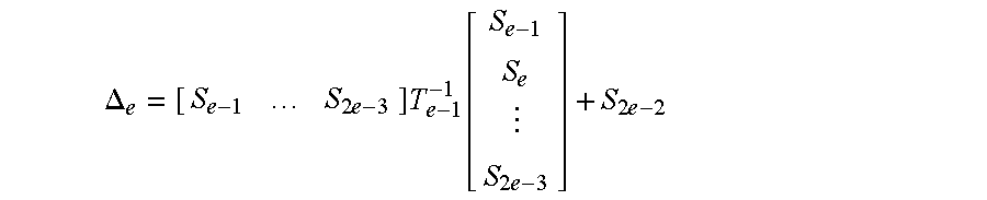
- ⁇ e denotes a value represented as follows.
- Inverse matrix T e ⁇ 1 is represented as follows by using these definitions.
- T e - 1 [ T e - 1 - 1 T e - 1 - 1 ⁇ e ⁇ [ S e - 1 ⁇ S 2 ⁇ e - 3 ] 0 1 ⁇ e ] ⁇ [ I e - 1 0 [ S e - 1 ... S 2 ⁇ e - 3 ] ⁇ T e - 1 - 1 1 ]
- Expression 9 indicates that when e errors have occurred the coefficients ⁇ k (e) of the error-locator polynomial can be calculated by using the coefficients ⁇ p (e ⁇ 1) , ⁇ q (e ⁇ 2) , . . . of the error-locator polynomial used when e ⁇ 1 errors or fewer have occurred. That is, the syndromes and the obtained coefficient ⁇ p (e ⁇ 1) are used to calculate, for the ascending order of e, the coefficients ⁇ k (e) that correspond to the e to be calculated.
- a circuit need not be prepared for each e, and a circuit for calculating a coefficient corresponding to a smaller value of e can be used as part of a circuit for calculating a coefficient corresponding to a greater value of e. As a result, the size of the overall circuit can be reduced.
- the matrix here differs in its symmetry from a well-known Teplitz matrix, and this very much complicates the problem.
- the coefficient actually required is only the coefficient corresponding to the actual number of errors e.
- the number of errors can be estimated as being, for example, the maximum number of e for which det(T e ) ⁇ 0.
- the coefficient calculation circuit 3 outputs, to the error location determination circuit 7 , coefficients ⁇ k that are the coefficients ⁇ k (e) of the error-locator polynomial corresponding to the number of estimated errors e.
- ⁇ 0 (3) ⁇ 0 (2) S 4 + ⁇ 1 (2) S 3 + ⁇ 2 (2) S 2
- ⁇ 0 (e) If ⁇ 0 (e) is not normalized, it need not be transmitted to the error location determination circuit 7 since ⁇ 0 (e) is 1.
- the present invention defines a new error polynomial, with which the error value is obtained by substituting the coefficient into the polynomial and, unlike the Forney algorithm, without a division being required after the coefficient has been substituted into the polynomial, and which, unlike Transform decoding, does not require term O(n).
- a (e) is a matrix before a matrix consisting of E 0 to E e ⁇ 1 is prepared.
- superscript is used for (e) in order to indicate that this is a matrix when the number of errors is e.
- An explanation will also be given for a i k , whereof a i is the element of the Galois field GF(2 m ) corresponding to the error location i, with i representing the overall order, and i k being used to indicate the order of the codeword that contain errors. Since the total number of errors is e, k is defined as having the values 0 to e ⁇ 1.
- the determinant of the denominator of expression 11 is called the Vandermonde determinant, and is represented by
- a determinant obtained by adding A ij (e) in expression with a superscripted “ ⁇ ” is a minor of A (e) .
- the equation can be solved if all the error locations are obtained. In this case, however, the calculation of O(e 3 ) is added to the inverse matrix calculation and the error locations must be calculated in advance, so that the calculation of the error values and the error locations cannot be performed at the same time. As is shown by the results described above, the coefficients of the error-locator polynomial and the syndromes are needed to represent expression 11. The denominator and the numerator in expression 11 will be separately explained.
- det(A (e) ) is the symmetric function for expression 13. Therefore, det(A (e) ) can be a function of ⁇ e (e) , ⁇ e ⁇ 1 (e) , . . . , ⁇ 1 (e) . In other words, it can be written as
- det( A (e) ) f ( ⁇ e (e) , ⁇ e ⁇ 1 (e) , . . . , ⁇ 1 (e) ).
- the calculation of the minor is a problem the numerator portion must contend with.
- a direct calculation is possible when e is a small number, but when e is increased, the calculation must be performed using a Schur function and a Young tableaux, referring to “Schur Function, Chiral Boson, And The Quantum-Hall-Effect Edge States,” M. Stone, Phys. Rev. B 42, 8399 (1990).
- the locations of the numerals enclosed by curly brackets ⁇ ⁇ represent the first row, the second row, . . . of the minor, reading from the right inside the curly brackets.
- the magnitude of the numeral represents the degree of incrementation of the order.
- the order of A (e) is incremented at a lower row. Since the minorji is a determinant that excludes the j-th row and the i-th column of A (e) , the order at the j-th and succeeding rows of the minor is incremented so that it is one higher than that of A (e) . Therefore,j ⁇ 1 0s are arranged from the right in the minor in expression 14, and e ⁇ j 1s are arranged at the j-th and the following rows of which the order is incremented so that it is one higher than that of A (e) .
- ⁇ 0 *, ⁇ 1 *, . . . , ⁇ e ⁇ 1 * ⁇ is the conjugate partition of ⁇ 0 , ⁇ 1 , . . . , ⁇ e ⁇ 1 ⁇ .
- FIG. 2 when viewed from the top, there are 4, 2, 2 and 1 blocks, and when viewed from the left, there are 4, 3, 1 and 1 blocks.
- the top view represents the state ⁇ 0 , ⁇ 1 , . . . , ⁇ e ⁇ 1 ⁇
- the left side view represents the state ⁇ 0 *, ⁇ 1 *, . . . , ⁇ e ⁇ 1 * ⁇ .
- the minor can be represented as a function of
- ⁇ 1 (e) ⁇ 1i k (e) +a i k
- ⁇ 2 (e) ⁇ 2i k (e) +a i k ⁇ 1i k (e) . . .
- ⁇ e ⁇ 1 (e) ⁇ e ⁇ 1i k (e) +a i k ⁇ e ⁇ 2i k (e)
- the numerator portion can be represented using the power i k of a, ⁇ e (e) , ⁇ e ⁇ 1 (e) , . . . , ⁇ 1 (e) , and S 0 , . . . , S 2e ⁇ 1 .
- E a ( ⁇ 1 (3) ⁇ 2 (3) + ⁇ 3 (3) ) ⁇ 1 ⁇ ( a a ( a a + ⁇ 1 (3) )+ ⁇ 2 (3) )( a a + ⁇ 1 (3) ) S 0 +( a a + ⁇ 1 (3) ) 2 S 1 +( a a + ⁇ 1 (3) ) S 2 ⁇ .
- the error value calculation circuit 5 receives coefficients Er 0 to Er ê of error polynomial Er(x).
- E i is calculated for all “i”s (0 to n ⁇ 1), E i is obtained even for a location whereat no error is present. Therefore, the calculation performed by the error location determination circuit 7 , which will be described later, is required to disable invalid values. Since a i is a constant value for each i, it is hard-wired, and a constant multiplier for receiving the coefficients Er 0 to Er ê is used.
- the error location determination circuit 7 receives coefficients ⁇ 0 to ⁇ e of error-locator polynomial ⁇ (x).
- the error locations can be designated using the following calculation that includes an IDFT. That is, ⁇ (a ⁇ 1 )?0.
- the “1” means that the output E i of the error value calculation circuit 5 is to be used, and the “0” means that E i is not to be used.
- a ⁇ i is hard-wired, and a constant multiplier for receiving the coefficients ⁇ 0 to ⁇ e is used.
- the error location determination circuit 7 and the error value calculation circuit 5 are shown as separate functional blocks, but these circuits can be integrally formed. Further, the output circuit 9 can also be integrally formed with these circuits. And in addition, when n or t is a very large number, one part of the circuit can be formed as a sequential circuit. For since the circuit arrangement of the present invention is very symmetric, a combinational circuit can be easily changed to a sequential circuit. Furthermore, while in this embodiment the coefficient calculation circuit 3 merely estimates the number of errors, a circuit can be provided that will actually count the number of errors.
- a high-speed, low power consumption Reed-Solomon decoder can be provided for which the parallel processing speed is increased. Further, since components such as a clock and a latch and a control circuit are not required, power consumption can be reduced.
- a Reed-Solomon decoder can be constituted by using only a combinational circuit, without a sequential circuit being used.
- the circuits can be generated and optimized more easily than it is in the prior art by using computer programs.
Abstract
A Reed-Solomon decoder that can correct t errors or fewer which includes: a syndrome calculation circuit for calculating syndromes Sj (J=0, 1, . . . , 2t−1) using the first codeword Yi (i=0, 1, . . . , n−1) (so-called received codeword) that may include errors; and a coefficient calculation circuit for, by using the syndromes Sj, calculating coefficients Λk (k=1, . . . , e) of an error-locator polynomial. The coefficients Λk correspond in number to e estimated errors (e≦t<n). The syndromes Sj, calculating coefficients Er1 (1=0, . . . , ê) (ê can be as small as O(e)) of an error polynomial, and the coefficients Er1 correspond in number to the e estimated errors. An error value calculation circuit for calculating error values Ei by using the coefficients Er1 of the error polynomial, and for using the coefficients Λk of the error-locator polynomial to generate a signal concerning the error value Ei to be used and an output circuit for using the first codeword Yi and the error value Ei, which correspond to the signal used to calculate the second codeword Wi (so-called source codeword) in which the estimated errors are corrected. Since e≦t<n, and since there are e coefficients Λk and e coefficients Er1, the number of calculations performed by, and the sizes of the coefficient calculation circuit and the error value calculation circuit are reduced. Specifically, since the coefficient calculation circuit requires gate-consuming non-linear operations in order to calculate the coefficients Λk and Er1, the effects achieved by such a reduction are greater.
Description
RS encoding and decoding can be defined as constituting a polynomial using the element in the Galois field GF(2m). The following codeword polynomial W(x) is calculated for (n, k) RS encoding where n denotes the number of code blocks and k denotes the number of information blocks (a test block is n−k=2t, where t is the maximum correctable number of symbols).
where
M(x): a polynomial using information symbols as coefficients;
R(x): a polynomial using parity symbols as coefficients;
R(x)=M(x)xn−k mod G(x); and
G(x): generator polynomial,
G(x)=(x−ad)(x−ad−1) . . . (x−ad+2t−1).
In the above equation, a is defined by GF(2m) and is a solution of the m-order irreducible polynomial, i.e., a solution that satisfies a8+a4+a3+a2+1=0 when m=8. The polynomial W(x) can be divided by G(x) without yielding a remainder. The codeword polynomial W(x) can be a systematic codeword, compared with a method that calls for the direct multiplication of M(x) by G(x).
Generally, an LFSR (Linear Feedback Shift Register) is used for calculating the remainder of the M(x)xn−k by G(x). If one LFSR is used for the encoding one block, the LFSR has 2t constant multipliers and uses them (n−2t) times. Thus, 2(n−2t)t constant multiplications must be performed for the encoding.
The RS decoding is an operation used for estimating the original W(x) by using a received polynomial
E(x) is a polynomial using an error symbol as a coefficient. Y(x) can also be expressed as follows, where Yi is a received codeword,
Y(x)=Y n−1 x n−1 +Y n−2 x n−2 + . . . Y 1 x+Y 0.
The decoding methods are mainly
(i) a method for using Y(x) to perform decoding in a time domain;
(ii) a method for using for a polynomial a remainder obtained by dividing Y(x) by G(x) (remainder-based decoding); and
(iii) a method for performing a DFT (Discrete Fourier Transformation) for Y(x) to calculate 2t continuous spectra (syndromes) in a frequency domain (syndrome-based decoding).
According to the second and the third methods, information that depends only on an error (i.e. syndromes) is calculated by using the received information, and the location of the error is extracted. Thus, the number of terms is not O(n), but instead is reduced to O(t). Therefore, since generally t<n, a required circuit in the succeeding stages is small. The third method (iii) is generally used, and is further sorted into algebraic decoding and transform decoding. The prior art will now be described by using the two decoding methods that are most closely related to the present invention.
(a) Algebraic Decoding
Specifically, this method includes the following five steps that must be performed for decoding:
(i) calculating a syndrome by performing a DFT for a received codeword;
(ii) obtaining an error-locator polynomial and an error-evaluator polynomial by using the calculated syndrome;
(iii) calculating the solution for the error-locator polynomial in order to estimate the location of the error;
(iv) estimating an error value from the error-locator and the error-evaluator polynomial by using the Forney algorithm; and
(v) correcting the error by using the received codeword and the error value.
In the calculation of the syndrome at step (i), the DFT calculation for GF(2m) need be performed. The DFT calculation is performed by substituting into Y(x) the elements 1, a, a2, a3 . . . and a2t−1 of GF(2m). That is, the syndrome is obtained by
S0=Y(1)
S1=Y(a)
S2=Y(a2)
S3=Y(a3)
.
.
.
S2t−1=Y(a2t−1).
Since W(ai)=0,
Si=Y(ai)=W(ai)+E(ai)=E(ai)(i=0, . . . , 2t−1).
The occurrence of an error in Y(x) can be determined by examining the syndromes to determine whether they are all 0. Since generally 2t arithmetic circuits are used n times to calculate the syndromes, 2nt constant multiplications are required.
Error correction using the syndromes is performed by estimating the number of errors using Si. This is the calculation performed with E(x) that provides the calculated syndrome and that has a Hamming weight of t or less (i.e., that includes non zero terms equal to or less than t), and is the NP complete problem in general. However, the calculation method in the polynomial order is well known for RS code. At step (ii) the coefficient for the following error-locator polynomial is calculated by using the fact that the syndromes can be expressed as a linear combination of error values, and that symmetry exists relative to the exchange of orders of error locations.

Coefficients Λt . . . and Λl for Λ(x) are obtained by the following expression, wherein L0 is defined as 1.
Expression 2 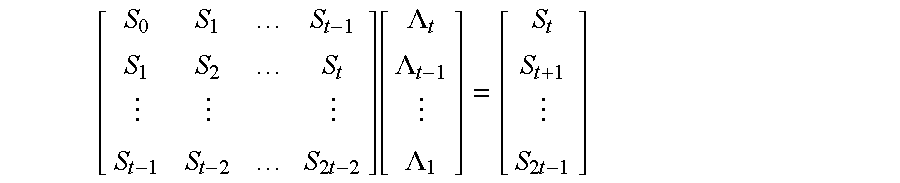
The Peterson method, the Berlekamp-Massey (BM) method and the Euclid method are proposed for performing this calculation in the polynomial order. According to these methods, O(t3), O(t2) and O(t2) multiplications are respectively performed to calculate the coefficients of the error-locator polynomial. Since these calculations are not directly related to the subject of the present invention, however, no further explanation shall be given for them. For the details, see the referenced document 1, “Theory And Practice Of Error Control Codes,” R. E. Blahut, Addison-Wesley 1984, or referenced document 2, “Coding Theory,” Hideki Imai, Institute of Electronic Information Communication, 1990.
When the coefficients Λt . . . and Λl of the error-locator polynomial are obtained, at step (iii) an error location i is obtained by performing the calculations for the polynomial. Generally, a−i (i=0, 1, . . . , n−1) are sequentially substituted into the error-locator polynomial, and the relation Λ(a−i)=0 is checked by using a sequential circuit (Chien Search). Since Λ(x) is the t-order polynomial, t constant multiplications must be repeated n times (a total of nt constant multiplications).
At step (iv), the Forney algorithm is used to calculate the error value by employing the following error-evaluator polynomial
where S(x) is the following polynomial having syndromes as coefficients:
Expression 3 
The obtained error value Ei is
where Λ′(x) represents the derivative of Λ(x).
Finally, at step (v) the error is corrected. That is,
Most of these calculations are performed as sequential steps using a sequential circuit, as previously mentioned. Specifically, steps (i) to (v) are sequentially performed, and at each step many processes are sequentially performed, including iterative calculations. The implementation of the RS decoder does not precipitate any problem in applications that has a relatively low data transfer rate. However, with a memory ECC application for which high through-put and low latency are required, a problem may arise concerning the processing speed.
The RS decoder requires only the linear calculation performed up to the acquisition of syndromes (step (i)), but for the following process to estimate the error location and error value, it requires multiple non-linear circuits. It is difficult to provide a small, fast circuit for the nonlinear calculation in the Galois field (a circuit for two-input multiplication, reciprocal calculation, etc.) using the basic logical function primitives (AND and XOR).
To resolve the problem concerning the processing speed, a combinational circuit can be provided. Actually, in BCH encoding, the part of the circuit used for calculating the coefficients of a polynomial is developed into a combinational circuit. The calculation expressions up to t=5 are represented, and an example for t=3 is disclosed in U.S. Pat. No. 5,343,481 However, in the design of the combinational circuit, a circuit sharing which is one of the design techniques that are frequently used in the design of sequential circuits is difficult. Therefore, unless the processing flow is so designed that the number of nonlinear operations is reduced, the number of nonlinear operating units required is increased in accordance with the number of iterative steps performed in a loop, a number that is increased in proportion to t, and the number of conditional branches in the loop. In addition, while in the BCH code only the error locations need be obtained, in the RS code not only the error locations but also the error values must be obtained. As a result, when t>1, the RS encoding uses more nonlinear operations than does the BCH encoding.
Because of the above described background, in most cases a conventional RS decoder is provided as a sequential circuit. In prior art, only when the maximum number of correctable symbols is small (t=1) the RS decoder is provided as a combinational circuit.
Specific problems will now be described that arise when algebraic decoding is implemented by using a combinational circuit.
(1) One problem arises when the Peterson method, the BM method or the Euclid method, which are frequently used to obtain the error-locator polynomial and the error-evaluator polynomial, are implemented as combinational circuits. Since the Peterson method provides a simple, direct method for the calculation of coefficients when the maximum number of correctable error symbol t is small (e.g., two), the Peterson method can be implemented by a combinational circuit. However, when the number of error symbols is increased, the size of the operations is increased as O(e3) when e is the actual number of error in the received codeword. Therefore, the Peterson method is implemented by using the combinational circuit, and circuits for the calculation of coefficient Λ(x) must be prepared in a number equivalent to the error count, which is equal to or smaller than t, so that the size of the circuit is increased by the amount
Expression 4 
instead of O(t3). The BM method provides a calculation algorithm that requires only the calculation amount O(t2). However, since a plurality of conditional branches are included in a single loop, it is not easy to increase the processing speed by using the algorithm to implement the combinational circuit within a practical number of gate size. Especially for RS encoding, the number of required loops is double that required for BCH encoding (see referenced documents 1 and 2). While the Euclid method also requires only the calculation amount O(t2), it includes the division by a polynomial, so that the size of a combinational circuit required to implement this method is unrealistically large.
(2) If, for the estimation of an error value, following the Chien Search, paths are merely arranged in parallel to constitute a combinational circuit, n dividers have to be prepared for the Forney Algorithm for the calculation of the error value. In this case, not all the dividers are effectively used; actually, only the dividers equivalent in number to the error corrections t are actually used. In addition, even when the dividers are designed to be used in common, the size of the circuit is not reduced very much, whereas the decoding speed is lowered considerably. This occurs because a circuit for allocating dividers in accordance with the error location requires 2t n-bit multiplexers (t multiplexers each at the preceding and succeeding stages) and t priority encoders.
(b) Transform Decoding
In the present invention, for decoding. the following five steps are performed:
(i) calculation of syndromes by performing a DFT for received codeword;
(ii) calculation of coefficients for an error-locator polynomial by using the obtained syndromes;
(iii) reflexive calculation of the DFT elements of n errors without resolving the error-locator polynomial;
(iv) calculation of error values by performing an IDFT (Inverse DFT); and
(v) correction of the errors by using the received codeword and the error values.
The method in (a) is used for steps (i) and (ii). At step (iii) the DFT elements E*i of the errors are obtained. Since the following relationship is established for the first 2t,
the high-order elements are calculated using
Expression 5 
where i=2t, . . . , n−1.
At step (iv), an IDFT is performed by substituting a−i (i=0, . . . n−1) into the polynomial that is defined bv using E*i as a coefficient. That is,
is used to calculate error value Ei.
The method described in (a) is performed at step (v).
Since a division circuit is not used for transform decoding, a problem precipitated by a division circuit, when method (a) is used to implement the combinational circuit, does not arise when method (b) is used. However, the following problems, in addition to the calculation of coefficient Λ(x), which is one ofthe problems that accompany the implementation of method (a), are encountered with method (b).
(1) While the same circuit in the sequential circuit can be iteratively used to calculate all the values Ei, n−2t circuits must be prepared for a combinational circuit. And since t 2-input multipliers are required for a single iteration, a total of t(n−2t) 2-input multipliers are required. In addition, since a recursive calculation is performed, i.e., a low-order calculation must be completed before a next-order calculation is begun, the calculation speed cannot be increased very much by implementing a combinational circuit.
(2) Since the error values are calculated after all the DFT elements for n errors are obtained from the syndromes, this algorithm is easily implemented by a combinational circuit, but for an IDFT, an enormous number of circuits must be used. That is, for an IDFT n2 constant multipliers are required.
It is, therefore, one object of the present invention to provide a high-speed, low power consumption Reed-Solomon decoder.
It is another object of the present invention to constitute a Reed-Solomon decoder by using only a combinational circuit, and without using a sequential circuit.
It is an additional object of the present invention to provide a Reed-Solomon decoder having a circuit size that can actually be achieved.
To achieve the above objects, according to the present invention, a Reed-Solomon decoder that can correct t errors or fewer comprises: a syndrome calculation circuit for calculating syndromes Sj (j=0, 1, . . . , 2t−1) using the first codeword Yi (i=0, 1, . . . , n−1) (so-called received codeword) that may include errors; a coefficient calculation circuit for, by using the syndromes Sj, calculating coefficients Λk (k=1, . . . , e) of an error-locator polynomial, the coefficients Λk corresponding in number to e estimated errors (e≦t<n), and for, by using the syndromes Sj, calculating coefficients Er1 (1=0, . . . , ê) (ê can be as small as O(e)) of an error polynomial, the coefficients Er1 corresponding in number to the e estimated errors; an error value calculation circuit for calculating error values Ei by using the coefficients Er1 of the error polynomial, and for using the coefficients Λk of the error-locator polynomial to generate a signal concerning the error value Ei to be used; and an output circuit for using the first codeword Yi and the error value Ei, which correspond to the signal used to calculate the second codeword Wi (so-called source codeword) in which the estimated errors are corrected. Since e≦t<n, and since there are e coefficients Λk and ê coefficients Er1, the number of calculations performed by, and the sizes of the coefficient calculation circuit and the error value calculation circuit are reduced. Specifically, since the coefficient circuit is required to perform a nonlinear operation in order to calculate the coefficients Λk and Er1, the effects achieved by such a reduction are greater.
At least one of the syndrome calculation circuit, the coefficient calculation circuit, the error value calculation circuit and the output circuit is constituted by a combinational circuit, as will be described later. And as a result, the calculation speed is increased.
The coefficient calculation circuit is so designed that it includes a circuit for calculating, in the ascending order of e coefficients Λw (e) (w=1, . . . , e) of an error-locator polynomial corresponding to the number e (e≦t) of errors by using the syndromes Sj and coefficients Λv (n−1) (v=1, . . . , e−1). By using this circuit in common, the size of the circuit can be limited.
The error value calculation circuit performs a calculation by using the element ai and the inverse element a−i of the Galois field GF(2m) corresponding to an error location i. In this case, by using a linear operation the calculation can be performed at high speed.
The coefficient calculation circuit may further use the coefficients Λk ofthe error-locator polynomial, which correspond to the estimated errors e, in order to calculate the coefficients Er1 of the error polynomial corresponding to the estimated errors e.
When a value of 0 is obtained by substituting the inverse element a−i of GF(2m) corresponding to the error location i, into the error-locator polynomial, the error value calculation circuit outputs a signal indicating the error values Ei are to be used. In the other cases, the error value calculation circuit outputs a signal indicating the error values Ei are not to be used.
The error value calculation circuit may include a constant multiplier for receiving the coefficients Er1 of the error polynomial, and a constant multiplier for receiving the coefficients Λk of the error-locator polynomial. When the element ad and the inverse element a−1 of the Galois field GF(2m) corresponding to the error location i are used, because the values are constants, the multipliers are hard-wired.
The thus arranged present invention can be applied for memory circuits for which high speed and low power consumption are demanded. These memory circuits are, for example, (i) a fast error correction circuit with low power consumption for extending the DRAM refresh time; (ii) a main memory redundancy circuit for a server for which high reliability and an adequate processing speed are desired; and (iii) a cache memory ECC circuit for which a high processing speed is desired.
A better understanding of the invention will be obtained by reference to the detailed description below, in conjunction with the following drawings in which:
FIG. 1 is a functional block diagram illustrating a Reed-Solomon decoder according to the present invention; and
FIG. 2 is a diagram for explaining conjugate partitions.
FIG. 1 is a functional block diagram illustrating a Reed-Solomon decoder according to the present invention. Received codeword Y0 to Yn−1 are transmitted to a syndrome calculation circuit 1 and an output circuit 9. The syndrome calculation circuit 1 is connected to a coefficient calculation circuit 3. Syndromes S0 to S2t−1, which are obtained by the syndrome calculation circuit 1, are transmitted to the coefficient calculation circuit 3. The coefficient calculation circuit 3 is connected to an error value calculation circuit 5 and an error location determination circuit 7. The coefficients Λ0 to Λe of the error-locator polynomial, which are obtained by the coefficient calculation circuit 3, are transmitted to the error location determination circuit 7, and the coefficients Er0 to Ere of the error polynomial are transmitted to the error value calculation circuit 5. It should be noted that e (e≦t<n) is the estimated number of errors. The error value calculation circuit 5 is connected to the output circuit 9. The error value Er(ai) (i=0, . . . , n−1) obtained by the error value calculation circuit 5 is transmitted to the output circuit 9. The error location determination circuit 7 is also connected to the output circuit 9, and a signal (Λ(a−i)?0) that is obtained by the error location determination circuit 7 and that represents an error value Er(a−i) to be used is transmitted to the output circuit 9. A signal of 1 is output when the coefficient Λ(a−i) is 0, and a signal of 0 is output when the coefficient Λ(a−i) is not 0. The output circuit 9 corrects the errors of the received codeword Y0 to Yn−1 by using the received error values Er(a−i) and the signal representing the error value Er(a−i) to be used, and outputs the obtained codeword W0 to Wn−1.
The decoder in FIG. 1 is characterized in that the syndrome calculation circuit 1 (for performing the DFT calculation), the error location determination circuit 7 (for performing the IDFT calculation), the error value calculation circuit 5 (for performing the DFT calculation) and the output circuit 9 concentrate on the linear operation, and the coefficient calculation circuit 3 in the middle concentrates on the non-linear operation. As a result, the number of inputs/outputs of the non-linear operation unit can be reduced, and the number of non-linear operation units, which constitutes a bottle-neck that adversely affects the reduction ofthe circuit size, does not depend on n.
This occurs because of the following properties of the decoder constituted by a combinational circuit.
(1) As a common tendency, only a small number of gates is required for a linear operation unit (a constant multiplier and an adder), whereas a multitude of gates is required for a non-linear operation unit (a multiplier, inversion and a divider). Generally, in GF(28), a linear operation circuit consists of several gates to several tens of gates, while a non-linear operation circuit has several hundreds to several thousands of gates.
(2) When a series of constant multiplications are performed in the GF(2m), they can be implemented at the same cost as that required for the preparation of one constant multiplier. However, when a non-linear operation is involved, the cost is increased, since a series of operations cannot be reduced to a single operation.
The arrangement of the present invention, wherein the linear operation units and the non-linear operation unit are provided separately and the number of inputs/outputs relative to the non-linear operation unit is reduced, can provide a local optimal solution in terms of the circuit size and the speed (the one that is considered close to the truly optimal solution). In addition, since the linear operation units and the non-linear operation unit are provided separately, automatic synthesization and verification can be easily performed by using computer programs.
The calculations to be performed by the individual components will now be described.
(1) Syndrome Calculation Circuit 1
The syndrome calculation circuit 1 performs the same calculation as in the prior art, i.e., performs the DFT calculation in GF(2m). This DFT calculation is performed by substituting elements 1, a, a2, a3, . . . and a2t−1 of GF(2m) into received codeword polynomial Y(x)=Yn−1xn−1+Yn−2xn−2+ . . . Y1x+Y0 that uses, as coefficients, received codeword Yi (i=0, . . . , n−1). In other words,
S0=Y(1)
S1=Y(a)
S2=Y(a2)
S3=Y(a3)
S2t−1=Y(a2t−1)
(2) Coefficient Calculation Circuit 3
As previously described, the coefficient calculation circuit 3 calculates coefficients Λk (e) (k=0, . . . , e) and coefficients Er1 (e) (1=0, . . . , e−1). First, an explanation will be given for the coefficients Λk (e) of the error-locator polynomial. The superscript (e) is used to indicate the number of errors is e.
(2-1) Calculation of Coefficients Λk (e) of Error-locator Polynomial
Expression 2 is calculated. Assume that t denotes the maximum number of errors that the decoder of the present invention can correct, and that e (0≦e<t) errors have occurred. Then, the matrix using S0 to S2t−2 in expression 2 can be represented as e×e matrix Te:
Expression 6 
Ie−1 denotes a (e−1)×(e−1) identity matrix, Te−1 denotes a matrix obtained by a one order reduction of Te, Te−1 −1 denotes the inverse matrix, and Λe denotes a value represented as follows.
Inverse matrix Te −1 is represented as follows by using these definitions.
Expression 8 
Thus, expression 6 can be modified as follows.
Expression 9 
It should be noted that the matrix here differs in its symmetry from a well-known Teplitz matrix, and this very much complicates the problem.
As is described above, the coefficients Λk (e) of the error-locator polynomial are calculated in order beginning with e=1. The coefficient actually required is only the coefficient corresponding to the actual number of errors e. The number of errors can be estimated as being, for example, the maximum number of e for which det(Te)≠0. The coefficient calculation circuit 3 outputs, to the error location determination circuit 7, coefficients Λk that are the coefficients Λk (e) of the error-locator polynomial corresponding to the number of estimated errors e.
The actual calculations up to e=3 are shown below with further reductions. For simplification, Λ0 (r) is normalized as Λ0 (r)=det(Tr).
Λ1 (1)=S1
Λ0 (1)=S0
Λ2 (2)=Λ1 (1)S3+S2 2
Λ1 (2)=Λ0 (1)S3+Λ1 (1)S2
Λ0 (2)=Λ0 (1)S2+Λ1 (1)S1
Λ3 (3)=ΛL2 (2)S5+S1S4 2+S3 3
Λ2 (3)=Λ1 (2)S5+Λ2 (2)S4+S0S4 2+S2S3 2
Λ1 (3)=Λ0 (2)S5+Λ1 (2)S4Λ2 (2)S3
Λ0 (3)=Λ0 (2)S4+Λ1 (2)S3+Λ2 (2)S2
If Λ0 (e) is not normalized, it need not be transmitted to the error location determination circuit 7 since Λ0 (e) is 1.
(2-2;) Calculation of Coefficients Er1 (e) of Error Polynomial
The present invention defines a new error polynomial, with which the error value is obtained by substituting the coefficient into the polynomial and, unlike the Forney algorithm, without a division being required after the coefficient has been substituted into the polynomial, and which, unlike Transform decoding, does not require term O(n).
Specifically, when e=3 the error polynomial is represented as follows.
Therefore,
Er3 (3)=(Λ1 (3)Λ2 (3)+Λ3 (3))−1S0
Er2 (3)=(Λ1 (3)Λ2 (3)+Λ3 (3))−1S1
Er1 (3)=(Λ1 (3)Λ2 (3)+Λ3 (3))−1(Λ1 (3)2S0+Λ2 (3)S0+S2)
Er0 (3)=(Λ1 (3)Λ2 (3)+Λ3 (3))−1(Λ2 (3)Λ2 (3)S0+Λ1 (3)2S1+Λ1 (3)S2)).
When e=2, the error polynomial is as follows.
Therefore,
Er2 (2)=0
Er1 (2)=(Λ0 (2)S0/Λ1 (2))
Er0 (2)=(S1 3+S0 2S3)/Λ1 (2).
When e=1, Er(1)(x)=S0. Therefore,
Er1 (1)=0
Er0 (1)=S0.
Also in this case, only coefficients Er1 (e) corresponding to the number of errors e are transmitted as Er1 to the error value calculation circuit 5.
An explanation will now be given of how the results are obtained. First, the following expression is established.
Expression 10 
wherein A(e) is a matrix before a matrix consisting of E0 to Ee−1 is prepared. Here, superscript is used for (e) in order to indicate that this is a matrix when the number of errors is e. An explanation will also be given for ai k, whereof ai is the element of the Galois field GF(2m) corresponding to the error location i, with i representing the overall order, and ik being used to indicate the order of the codeword that contain errors. Since the total number of errors is e, k is defined as having the values 0 to e−1.
Since i0 to ie−1 are not the same, an inverse matrix of the matrix A(e) is provided, and thus a solution is provided for expression 10. That is,
Expression 11 
wherein k=0, . . . , e−1. The determinant of the denominator of expression 11 is called the Vandermonde determinant, and is represented by
Expression 12
Further, a determinant obtained by adding Aij (e) in expression with a superscripted “˜” is a minor of A(e).
The equation can be solved if all the error locations are obtained. In this case, however, the calculation of O(e3) is added to the inverse matrix calculation and the error locations must be calculated in advance, so that the calculation of the error values and the error locations cannot be performed at the same time. As is shown by the results described above, the coefficients of the error-locator polynomial and the syndromes are needed to represent expression 11. The denominator and the numerator in expression 11 will be separately explained.
(a) Denominator in Expression 11
While taking into account that
is the elementary symmetric function of
Expression 13
since the sum and the difference are the same in the Galois field, det(A(e)) is the symmetric function for expression 13. Therefore, det(A(e)) can be a function of Λe (e), Λe−1 (e), . . . , Λ1 (e). In other words, it can be written as
For the proof, see “Algebra,” B. L. Van Der Vaerden, Frederick Ungar Publishing Co., 1970.
For example,
det(A(2))=Λ1 (2)
det(A(3))=Λ1 (3)Λ2 (3)+Λ3 (3).
(b) Numerator in Expression 11
The calculation of the minor is a problem the numerator portion must contend with. A direct calculation is possible when e is a small number, but when e is increased, the calculation must be performed using a Schur function and a Young tableaux, referring to “Schur Function, Chiral Boson, And The Quantum-Hall-Effect Edge States,” M. Stone, Phys. Rev. B 42, 8399 (1990).
Expression 14 
The locations of the numerals enclosed by curly brackets { } represent the first row, the second row, . . . of the minor, reading from the right inside the curly brackets. The magnitude of the numeral represents the degree of incrementation of the order. The order of A(e) is incremented at a lower row. Since the minorji is a determinant that excludes the j-th row and the i-th column of A(e), the order at the j-th and succeeding rows of the minor is incremented so that it is one higher than that of A(e). Therefore,j−1 0s are arranged from the right in the minor in expression 14, and e−j 1s are arranged at the j-th and the following rows of which the order is incremented so that it is one higher than that of A(e).
Expression 15 
{λ0*, λ1*, . . . , λe−1*} is the conjugate partition of {λ0, λ1, . . . , λe−1}. An explanation will be given by using an example in FIG. 2. In FIG. 2, when viewed from the top, there are 4, 2, 2 and 1 blocks, and when viewed from the left, there are 4, 3, 1 and 1 blocks. The top view represents the state {λ0, λ1, . . . , λe−1}, and the left side view represents the state {λ0*, λ1*, . . . , λe−1*}.
Expression 16
is a determinant obtained by deleting from A(e) a row including the power ik of a and a row including the powers (e−1)ik of a.
Therefore, the minor can be represented as a function of
Expression 17
That is, it can be described by
Expression 18 
Further, since
Expression 19
the numerator portion can be represented using the power ik of a, Λe (e), Λe−1 (e), . . . , Λ1 (e), and S0, . . . , S2e−1. To conclude,
Expression 20
can be represented as a polynomial of the power ik of a, the coefficients for which are constituted Λe (e), Λe−1 (e), . . . , Λ1 (e), and S0, . . . , S2e−1.
An explanation will now be given referring to an example for which of e=3. The error locations ik are α, β and γ. The values of A(e) are as follows.
Expression 21 
Thus, the minors can be represented as follows.
Expression 22 
Expression 23 
Expression 24 
Since the conjugate partition of {1,1} {1,0} {0,0} is {2,0} {1,0} {0,0}, the Schur functions are represented as follows.
Expression 25 
Expression 26 
Expression 27 
In expression 25 Φ{1,1}a=aβaγand in expression 26 Φ{1,0}a=aβ+aγare introduced from expressions 22 and 23.
Then,
Expression 28
Expression 29
Expression 30
are obtained. Therefore,
Thus, the expression obtained by substituting x into aa in the above expression is the expression for the error polynomial (e=3). It should be noted that this is an operation in the Galois field.
(3) Error Value Calculation Circuit 5
The error value calculation circuit 5 receives coefficients Er0 to Erê of error polynomial Er(x). The error values are obtained by substituting the element ai (i=0, . . . , n−1) in GF(2m) into x in error polynomial Er(x), which is constituted by the coefficients Er0 to Erê. That is,
and a DFT is performed. Since Ei is calculated for all “i”s (0 to n−1), Ei is obtained even for a location whereat no error is present. Therefore, the calculation performed by the error location determination circuit 7, which will be described later, is required to disable invalid values. Since ai is a constant value for each i, it is hard-wired, and a constant multiplier for receiving the coefficients Er0 to Erê is used.
(4) Error Location Determination Circuit 7
The error location determination circuit 7 receives coefficients Λ0 to Λe of error-locator polynomial Λ(x). The error locations can be designated using the following calculation that includes an IDFT. That is, Λ(a−1)?0. At the error location i, a is the inverse element in GF(2m), and Λ(a−i)?0 means that when, as the result of a comparison, Λ(a−i)=0, a “1” is output, while in other cases, a “0” is output. The “1” means that the output Ei of the error value calculation circuit 5 is to be used, and the “0” means that Ei is not to be used. In this case also, a−i is hard-wired, and a constant multiplier for receiving the coefficients Λ0 to Λe is used.
(5) Output Circuit 9
The output circuit 9 outputs codeword W0 to Wn−1 for which errors have been corrected. At this time, Er(ai)·(Λ(a−i)?0) is executed. As is described in the subdivision of the background, since W(x)=Y(x)+E(x), Er(ai)·(Λ(a−i)?0) and Yi are added together (XORed), and the codeword Wi for which errors have been corrected can be obtained.
The above embodiment is merely an example, and can be modified in various ways. For example, in this embodiment the error location determination circuit 7 and the error value calculation circuit 5 are shown as separate functional blocks, but these circuits can be integrally formed. Further, the output circuit 9 can also be integrally formed with these circuits. And in addition, when n or t is a very large number, one part of the circuit can be formed as a sequential circuit. For since the circuit arrangement of the present invention is very symmetric, a combinational circuit can be easily changed to a sequential circuit. Furthermore, while in this embodiment the coefficient calculation circuit 3 merely estimates the number of errors, a circuit can be provided that will actually count the number of errors.
In summary, a high-speed, low power consumption Reed-Solomon decoder can be provided for which the parallel processing speed is increased. Further, since components such as a clock and a latch and a control circuit are not required, power consumption can be reduced.
In addition, a Reed-Solomon decoder can be constituted by using only a combinational circuit, without a sequential circuit being used.
Even when the combinational circuit is used, a Reed-Solomon decoder having a circuit size that actually be achieved.
The circuits can be generated and optimized more easily than it is in the prior art by using computer programs.
A person understanding this invention may now conceive of alternative structures and embodiments or variations of the above. All of those which fall within the scope of the claims appended hereto are considered to be part of the present invention.
Claims (7)
1. A Reed-Solomon decoder that can correct t errors or fewer comprising:
a syndrome calculation circuit for calculating syndromes Sj (J=0, 1, . . . , 2t−1) using the first codeword Yi (i=0, 1, . . . , n−1) that may include errors;
a coefficient calculation circuit for, by using said syndromes Sj, calculating coefficients Λk (k=1, . . . , e) of an error-lccator polynomial, said coefficients Λk corresponding to e estimated errors (e≦t<n), and for, by using said syndromes Sj, calculating coefficients Er1 (1=0, . . . , ê) (ê can be as small as O(e)) of a single error polynomial, said coefficients Er1 corresponding to said e estimated errors;
an error value calculation circuit for calculating error values Ei by using said coefficients Er1 of said error polynomial, and for using said coefficients Λk of said error-locator polynomial to generate a signal concerning said error value Ei to be used; and
an output circuit for using said first codeword Yi and said error value Ei, which correspond to said signal used to calculate the second codeword Wi in which said estimated errors are corrected.
2. The Reed-Solomon decoder according to claim 1 , wherein at least one of said syndrome calculation circuit, said coefficient calculation circuit, said error value calculation circuit and said output circuit is constituted by a combinational circuit.
3. The Reed-Solomon decoder according to claim 1 , wherein said coefficient calculation circuit includes a circuit for calculating, in the ascending order of e, coefficients Λw (e) (w=1, . . . , e) of an error-locator polynomial that correspond to the number e (e≦t) of errors by using said syndromes Sj and coefficients Λv (e−1) (v=1, . . . , e−1).
4. The Reed-Solomon decoder according to claim 1 , wherein said coefficient calculation circuit further uses said coefficients Λk of said error-locator polynomial, which correspond to said estimated errors e, in order to calculate said coefficients Er1 of said error polynomial corresponding to said estimated errors e.
5. The Reed-Solomon decoder according to claim 4 , wherein, when a value of 0 is obtained by substituting said inverse element a−i of GF(2m) corresponding to said error location i, into said error-locator polynomial, said error value calculation circuit outputs a signal indicating said error values Ei are to be used, and when other values are obtained, outputs a signal indicating said error values Ei are not to be used.
6. The Reed-Solomon decoder according to claim 1 , wherein said error value calculation circuit performs a calculation by using the element ai and the inverse element a−i of the Galois field GF(2m) that corresponds to an error location i.
7. The Reed-Solomon decoder according to claim 6 , wherein said error value calculation circuit includes a constant multiplier for receiving said coefficients Er1 of said error polynomial, and a constant multiplier for receiving said coefficients Λk of said error-locator polynomial.
Applications Claiming Priority (2)
| Application Number | Priority Date | Filing Date | Title |
|---|---|---|---|
| JP10-268493 | 1998-09-22 | ||
| JP26849398A JP3272307B2 (en) | 1998-09-22 | 1998-09-22 | Reed-Solomon decoding circuit |
Publications (1)
| Publication Number | Publication Date |
|---|---|
| US6487691B1 true US6487691B1 (en) | 2002-11-26 |
Family
ID=17459274
Family Applications (1)
| Application Number | Title | Priority Date | Filing Date |
|---|---|---|---|
| US09/401,051 Expired - Fee Related US6487691B1 (en) | 1998-09-22 | 1999-09-22 | Reed-solomon decoder |
Country Status (2)
| Country | Link |
|---|---|
| US (1) | US6487691B1 (en) |
| JP (1) | JP3272307B2 (en) |
Cited By (13)
| Publication number | Priority date | Publication date | Assignee | Title |
|---|---|---|---|---|
| US6640327B1 (en) * | 2000-11-01 | 2003-10-28 | Sharp Laboratories Of America, Inc. | Fast BCH error detection and correction using generator polynomial permutation |
| US6704901B1 (en) * | 2000-07-11 | 2004-03-09 | Ami Semiconductor, Inc. | Runtime programmable Reed-Solomon decoder |
| US20040199857A1 (en) * | 2003-03-12 | 2004-10-07 | Matsushita Electric Industrial Co., Ltd. | Method and device for decoding reed-solomon code or extended reed-solomon code |
| US20080104487A1 (en) * | 2006-10-31 | 2008-05-01 | Fujitsu Limited | Error detection apparatus and error detection method |
| US20080145064A1 (en) * | 2006-12-13 | 2008-06-19 | Masaki Ohira | Optical line terminal and optical network terminal |
| US20080320371A1 (en) * | 2007-06-23 | 2008-12-25 | Lite-On Technology Corp. | Efficient chien search method in reed-solomon decoding, and machine-readable recording medium including instructions for executing the method |
| US20090187812A1 (en) * | 2008-01-17 | 2009-07-23 | Nobuo Abe | Processing module, error correction decoding circuit, and processing method for error locator polynomial |
| US7774688B1 (en) * | 2006-10-11 | 2010-08-10 | Marvell International Ltd. | Hardware efficient decoding system for Bose, Ray-Chaudhuri, Hocquenghem (BCH) product codes |
| US7793195B1 (en) * | 2006-05-11 | 2010-09-07 | Link—A—Media Devices Corporation | Incremental generation of polynomials for decoding reed-solomon codes |
| US20110055668A1 (en) * | 2009-09-02 | 2011-03-03 | Texas Instruments Incorporated | Method, device, and digital circuity for providing a closed-form solution to a scaled error locator polynomial used in bch decoding |
| US8171368B1 (en) * | 2007-02-16 | 2012-05-01 | Link—A—Media Devices Corporation | Probabilistic transition rule for two-level decoding of reed-solomon codes |
| US20140108895A1 (en) * | 2012-10-15 | 2014-04-17 | Samsung Electronics Co., Ltd. | Error correction code circuit and memory device including the same |
| US8739006B2 (en) | 2010-06-30 | 2014-05-27 | International Business Machines Corporation | Reduced circuit implementation of encoder and syndrome generator |
Families Citing this family (1)
| Publication number | Priority date | Publication date | Assignee | Title |
|---|---|---|---|---|
| JP5918884B1 (en) * | 2015-05-12 | 2016-05-18 | 日本電信電話株式会社 | Decoding device, decoding method, and program |
Citations (8)
| Publication number | Priority date | Publication date | Assignee | Title |
|---|---|---|---|---|
| US4845714A (en) * | 1987-06-08 | 1989-07-04 | Exabyte Corporation | Multiple pass error correction process and apparatus for product codes |
| US5226043A (en) * | 1990-12-27 | 1993-07-06 | Raytheon Company | Apparatus and method for data error detection and correction and address error detection in a memory system |
| US5343481A (en) * | 1991-01-07 | 1994-08-30 | Kraft Clifford H | BCH error-location polynomial decoder |
| JPH06260943A (en) | 1993-03-04 | 1994-09-16 | Matsushita Electric Ind Co Ltd | Error correction device |
| JPH0916423A (en) | 1995-06-28 | 1997-01-17 | Fanuc Ltd | Error correcting method |
| US5610929A (en) * | 1994-03-11 | 1997-03-11 | Fujitsu Limited | Multibyte error correcting system |
| US5983383A (en) * | 1997-01-17 | 1999-11-09 | Qualcom Incorporated | Method and apparatus for transmitting and receiving concatenated code data |
| US6275965B1 (en) * | 1997-11-17 | 2001-08-14 | International Business Machines Corporation | Method and apparatus for efficient error detection and correction in long byte strings using generalized, integrated, interleaved reed-solomon codewords |
-
1998
- 1998-09-22 JP JP26849398A patent/JP3272307B2/en not_active Expired - Fee Related
-
1999
- 1999-09-22 US US09/401,051 patent/US6487691B1/en not_active Expired - Fee Related
Patent Citations (8)
| Publication number | Priority date | Publication date | Assignee | Title |
|---|---|---|---|---|
| US4845714A (en) * | 1987-06-08 | 1989-07-04 | Exabyte Corporation | Multiple pass error correction process and apparatus for product codes |
| US5226043A (en) * | 1990-12-27 | 1993-07-06 | Raytheon Company | Apparatus and method for data error detection and correction and address error detection in a memory system |
| US5343481A (en) * | 1991-01-07 | 1994-08-30 | Kraft Clifford H | BCH error-location polynomial decoder |
| JPH06260943A (en) | 1993-03-04 | 1994-09-16 | Matsushita Electric Ind Co Ltd | Error correction device |
| US5610929A (en) * | 1994-03-11 | 1997-03-11 | Fujitsu Limited | Multibyte error correcting system |
| JPH0916423A (en) | 1995-06-28 | 1997-01-17 | Fanuc Ltd | Error correcting method |
| US5983383A (en) * | 1997-01-17 | 1999-11-09 | Qualcom Incorporated | Method and apparatus for transmitting and receiving concatenated code data |
| US6275965B1 (en) * | 1997-11-17 | 2001-08-14 | International Business Machines Corporation | Method and apparatus for efficient error detection and correction in long byte strings using generalized, integrated, interleaved reed-solomon codewords |
Cited By (21)
| Publication number | Priority date | Publication date | Assignee | Title |
|---|---|---|---|---|
| US6704901B1 (en) * | 2000-07-11 | 2004-03-09 | Ami Semiconductor, Inc. | Runtime programmable Reed-Solomon decoder |
| US6640327B1 (en) * | 2000-11-01 | 2003-10-28 | Sharp Laboratories Of America, Inc. | Fast BCH error detection and correction using generator polynomial permutation |
| US20040199857A1 (en) * | 2003-03-12 | 2004-10-07 | Matsushita Electric Industrial Co., Ltd. | Method and device for decoding reed-solomon code or extended reed-solomon code |
| US7206993B2 (en) * | 2003-03-12 | 2007-04-17 | Matsushita Electric Industrial Co., Ltd. | Method and device for decoding Reed-Solomon code or extended Reed-Solomon code |
| US7793195B1 (en) * | 2006-05-11 | 2010-09-07 | Link—A—Media Devices Corporation | Incremental generation of polynomials for decoding reed-solomon codes |
| US8650466B2 (en) | 2006-05-11 | 2014-02-11 | Sk Hynix Memory Solutions Inc. | Incremental generation of polynomials for decoding reed-solomon codes |
| US20100287451A1 (en) * | 2006-05-11 | 2010-11-11 | Link_A_Media Devices Corporation | Incremental generation of polynomials for decoding reed-solomon codes |
| US7774688B1 (en) * | 2006-10-11 | 2010-08-10 | Marvell International Ltd. | Hardware efficient decoding system for Bose, Ray-Chaudhuri, Hocquenghem (BCH) product codes |
| US20080104487A1 (en) * | 2006-10-31 | 2008-05-01 | Fujitsu Limited | Error detection apparatus and error detection method |
| US20080145064A1 (en) * | 2006-12-13 | 2008-06-19 | Masaki Ohira | Optical line terminal and optical network terminal |
| US7978972B2 (en) * | 2006-12-13 | 2011-07-12 | Hitachi, Ltd. | Optical line terminal and optical network terminal |
| US8171368B1 (en) * | 2007-02-16 | 2012-05-01 | Link—A—Media Devices Corporation | Probabilistic transition rule for two-level decoding of reed-solomon codes |
| US7984366B2 (en) * | 2007-06-23 | 2011-07-19 | Lite-On Technology Corp. | Efficient chien search method in reed-solomon decoding, and machine-readable recording medium including instructions for executing the method |
| US20080320371A1 (en) * | 2007-06-23 | 2008-12-25 | Lite-On Technology Corp. | Efficient chien search method in reed-solomon decoding, and machine-readable recording medium including instructions for executing the method |
| US20090187812A1 (en) * | 2008-01-17 | 2009-07-23 | Nobuo Abe | Processing module, error correction decoding circuit, and processing method for error locator polynomial |
| US8335973B2 (en) * | 2008-01-17 | 2012-12-18 | Hitachi, Ltd. | Processing module, error correction decoding circuit, and processing method for error locator polynomial |
| US20110055668A1 (en) * | 2009-09-02 | 2011-03-03 | Texas Instruments Incorporated | Method, device, and digital circuity for providing a closed-form solution to a scaled error locator polynomial used in bch decoding |
| US8392806B2 (en) * | 2009-09-02 | 2013-03-05 | Texas Instruments Incorporated | Method, device, and digital circuitry for providing a closed-form solution to a scaled error locator polynomial used in BCH decoding |
| US8739006B2 (en) | 2010-06-30 | 2014-05-27 | International Business Machines Corporation | Reduced circuit implementation of encoder and syndrome generator |
| US20140108895A1 (en) * | 2012-10-15 | 2014-04-17 | Samsung Electronics Co., Ltd. | Error correction code circuit and memory device including the same |
| US9130592B2 (en) * | 2012-10-15 | 2015-09-08 | Samsung Electronics Co., Ltd. | Error correction code circuit and memory device including the same |
Also Published As
| Publication number | Publication date |
|---|---|
| JP2000114984A (en) | 2000-04-21 |
| JP3272307B2 (en) | 2002-04-08 |
Similar Documents
| Publication | Publication Date | Title |
|---|---|---|
| US4873688A (en) | High-speed real-time Reed-Solomon decoder | |
| US6637002B1 (en) | Decoder for error correcting block codes | |
| US6684364B2 (en) | Forward error corrector | |
| US6487691B1 (en) | Reed-solomon decoder | |
| US6347389B1 (en) | Pipelined high speed reed-solomon error/erasure decoder | |
| US10389385B2 (en) | BM-based fast chase decoding of binary BCH codes through degenerate list decoding | |
| EP0648021A2 (en) | Time domain algebraic encoder/decoder | |
| US6286123B1 (en) | Circuit for calculating error position polynomial at high speed | |
| US7353449B2 (en) | Method of soft-decision decoding of Reed-Solomon codes | |
| US8099655B1 (en) | Galois field multiplier system and method | |
| Li et al. | On transform-domain error and erasure correction by Gabidulin codes | |
| US9191029B2 (en) | Additional error correction apparatus and method | |
| Trifonov | Low-complexity implementation of RAID based on Reed-Solomon codes | |
| Wang | Hierarchical decoding of double error correcting codes for high speed reliable memories | |
| US20080140740A1 (en) | Systems and methods for processing data sets in parallel | |
| US20030159103A1 (en) | Efficient method for fast decoding of BCH binary codes | |
| US20030126543A1 (en) | Method and apparatus for solving key equation polynomials in decoding error correction codes | |
| US20060010363A1 (en) | Method and system for correcting low latency errors in read and write non volatile memories, particularly of the flash type | |
| US8255777B2 (en) | Systems and methods for locating error bits in encoded data | |
| KR102573306B1 (en) | Fast chase decoding method of generalized reed-solomon codes using groebner basis | |
| US7693927B2 (en) | Data processing system and method | |
| Hariri et al. | Fault detection structures for the Montgomery multiplication over binary extension fields | |
| Zheng et al. | An efficient eligible error locator polynomial searching algorithm and hardware architecture for one-pass Chase decoding of BCH codes | |
| Prashanthi et al. | An advanced low complexity double error correction of an BCH decoder | |
| US20180131388A1 (en) | Method of arrangement of an algorithm in cyclic redundancy check |
Legal Events
| Date | Code | Title | Description |
|---|---|---|---|
| AS | Assignment |
Owner name: INTERNATIONAL BUSINESS MACHINES CORPORATION, NEW Y Free format text: ASSIGNMENT OF ASSIGNORS INTEREST;ASSIGNORS:KATAYAMA, YASUNAO;MORIOKA, SUMIO;REEL/FRAME:010273/0557 Effective date: 19990921 |
|
| FEPP | Fee payment procedure |
Free format text: PAYOR NUMBER ASSIGNED (ORIGINAL EVENT CODE: ASPN); ENTITY STATUS OF PATENT OWNER: LARGE ENTITY |
|
| FPAY | Fee payment |
Year of fee payment: 4 |
|
| REMI | Maintenance fee reminder mailed | ||
| LAPS | Lapse for failure to pay maintenance fees | ||
| STCH | Information on status: patent discontinuation |
Free format text: PATENT EXPIRED DUE TO NONPAYMENT OF MAINTENANCE FEES UNDER 37 CFR 1.362 |
|
| FP | Lapsed due to failure to pay maintenance fee |
Effective date: 20101126 |