US6489595B1 - Electric heater for a seat assembly - Google Patents
Electric heater for a seat assembly Download PDFInfo
- Publication number
- US6489595B1 US6489595B1 US09/804,423 US80442301A US6489595B1 US 6489595 B1 US6489595 B1 US 6489595B1 US 80442301 A US80442301 A US 80442301A US 6489595 B1 US6489595 B1 US 6489595B1
- Authority
- US
- United States
- Prior art keywords
- carrier member
- electric heater
- heating element
- heater
- seat cushion
- Prior art date
- Legal status (The legal status is an assumption and is not a legal conclusion. Google has not performed a legal analysis and makes no representation as to the accuracy of the status listed.)
- Expired - Lifetime, expires
Links
- 239000006260 foam Substances 0.000 claims abstract description 20
- 239000000853 adhesive Substances 0.000 claims description 21
- 230000001070 adhesive effect Effects 0.000 claims description 21
- 239000004020 conductor Substances 0.000 claims description 19
- 239000000463 material Substances 0.000 claims description 18
- 238000000034 method Methods 0.000 claims description 12
- 238000000465 moulding Methods 0.000 claims description 12
- 239000006261 foam material Substances 0.000 claims description 8
- 229920003023 plastic Polymers 0.000 claims description 8
- 239000004033 plastic Substances 0.000 claims description 8
- 239000002390 adhesive tape Substances 0.000 claims description 7
- 239000008258 liquid foam Substances 0.000 claims description 7
- 230000002787 reinforcement Effects 0.000 claims description 4
- 239000002984 plastic foam Substances 0.000 claims description 2
- 230000003014 reinforcing effect Effects 0.000 claims 1
- 238000010438 heat treatment Methods 0.000 abstract description 68
- 239000013518 molded foam Substances 0.000 abstract description 6
- 210000001217 buttock Anatomy 0.000 description 17
- 239000004744 fabric Substances 0.000 description 7
- 239000004831 Hot glue Substances 0.000 description 4
- 229920005830 Polyurethane Foam Polymers 0.000 description 4
- 239000007788 liquid Substances 0.000 description 4
- 239000011496 polyurethane foam Substances 0.000 description 4
- 125000000391 vinyl group Chemical group [H]C([*])=C([H])[H] 0.000 description 4
- 229920002554 vinyl polymer Polymers 0.000 description 4
- JOYRKODLDBILNP-UHFFFAOYSA-N Ethyl urethane Chemical compound CCOC(N)=O JOYRKODLDBILNP-UHFFFAOYSA-N 0.000 description 3
- 230000006835 compression Effects 0.000 description 3
- 238000007906 compression Methods 0.000 description 3
- 229920002635 polyurethane Polymers 0.000 description 3
- 239000004814 polyurethane Substances 0.000 description 3
- 229920001944 Plastisol Polymers 0.000 description 2
- 239000004820 Pressure-sensitive adhesive Substances 0.000 description 2
- 239000011248 coating agent Substances 0.000 description 2
- 238000000576 coating method Methods 0.000 description 2
- 238000010276 construction Methods 0.000 description 2
- 210000003414 extremity Anatomy 0.000 description 2
- 239000002184 metal Substances 0.000 description 2
- 238000012986 modification Methods 0.000 description 2
- 230000004048 modification Effects 0.000 description 2
- 239000004999 plastisol Substances 0.000 description 2
- 125000006850 spacer group Chemical group 0.000 description 2
- 239000007921 spray Substances 0.000 description 2
- 239000012209 synthetic fiber Substances 0.000 description 2
- 229920002994 synthetic fiber Polymers 0.000 description 2
- OKTJSMMVPCPJKN-UHFFFAOYSA-N Carbon Chemical compound [C] OKTJSMMVPCPJKN-UHFFFAOYSA-N 0.000 description 1
- 229920001247 Reticulated foam Polymers 0.000 description 1
- NIXOWILDQLNWCW-UHFFFAOYSA-N acrylic acid group Chemical group C(C=C)(=O)O NIXOWILDQLNWCW-UHFFFAOYSA-N 0.000 description 1
- 239000003522 acrylic cement Substances 0.000 description 1
- MTAZNLWOLGHBHU-UHFFFAOYSA-N butadiene-styrene rubber Chemical compound C=CC=C.C=CC1=CC=CC=C1 MTAZNLWOLGHBHU-UHFFFAOYSA-N 0.000 description 1
- 229910052799 carbon Inorganic materials 0.000 description 1
- 239000003610 charcoal Substances 0.000 description 1
- 229940083342 drysol Drugs 0.000 description 1
- 230000000694 effects Effects 0.000 description 1
- 238000005485 electric heating Methods 0.000 description 1
- 230000005611 electricity Effects 0.000 description 1
- 238000005516 engineering process Methods 0.000 description 1
- 229920001821 foam rubber Polymers 0.000 description 1
- 239000012943 hotmelt Substances 0.000 description 1
- 239000010985 leather Substances 0.000 description 1
- 238000004519 manufacturing process Methods 0.000 description 1
- 238000005065 mining Methods 0.000 description 1
- 239000006223 plastic coating Substances 0.000 description 1
- 229920006264 polyurethane film Polymers 0.000 description 1
- 239000011148 porous material Substances 0.000 description 1
- 239000007787 solid Substances 0.000 description 1
- 239000004753 textile Substances 0.000 description 1
Images


Classifications
-
- B—PERFORMING OPERATIONS; TRANSPORTING
- B29—WORKING OF PLASTICS; WORKING OF SUBSTANCES IN A PLASTIC STATE IN GENERAL
- B29C—SHAPING OR JOINING OF PLASTICS; SHAPING OF MATERIAL IN A PLASTIC STATE, NOT OTHERWISE PROVIDED FOR; AFTER-TREATMENT OF THE SHAPED PRODUCTS, e.g. REPAIRING
- B29C66/00—General aspects of processes or apparatus for joining preformed parts
- B29C66/69—General aspects of joining filaments
-
- B—PERFORMING OPERATIONS; TRANSPORTING
- B29—WORKING OF PLASTICS; WORKING OF SUBSTANCES IN A PLASTIC STATE IN GENERAL
- B29C—SHAPING OR JOINING OF PLASTICS; SHAPING OF MATERIAL IN A PLASTIC STATE, NOT OTHERWISE PROVIDED FOR; AFTER-TREATMENT OF THE SHAPED PRODUCTS, e.g. REPAIRING
- B29C65/00—Joining or sealing of preformed parts, e.g. welding of plastics materials; Apparatus therefor
- B29C65/02—Joining or sealing of preformed parts, e.g. welding of plastics materials; Apparatus therefor by heating, with or without pressure
-
- B—PERFORMING OPERATIONS; TRANSPORTING
- B29—WORKING OF PLASTICS; WORKING OF SUBSTANCES IN A PLASTIC STATE IN GENERAL
- B29C—SHAPING OR JOINING OF PLASTICS; SHAPING OF MATERIAL IN A PLASTIC STATE, NOT OTHERWISE PROVIDED FOR; AFTER-TREATMENT OF THE SHAPED PRODUCTS, e.g. REPAIRING
- B29C66/00—General aspects of processes or apparatus for joining preformed parts
- B29C66/70—General aspects of processes or apparatus for joining preformed parts characterised by the composition, physical properties or the structure of the material of the parts to be joined; Joining with non-plastics material
- B29C66/72—General aspects of processes or apparatus for joining preformed parts characterised by the composition, physical properties or the structure of the material of the parts to be joined; Joining with non-plastics material characterised by the structure of the material of the parts to be joined
- B29C66/727—General aspects of processes or apparatus for joining preformed parts characterised by the composition, physical properties or the structure of the material of the parts to be joined; Joining with non-plastics material characterised by the structure of the material of the parts to be joined being porous, e.g. foam
-
- B—PERFORMING OPERATIONS; TRANSPORTING
- B60—VEHICLES IN GENERAL
- B60N—SEATS SPECIALLY ADAPTED FOR VEHICLES; VEHICLE PASSENGER ACCOMMODATION NOT OTHERWISE PROVIDED FOR
- B60N2/00—Seats specially adapted for vehicles; Arrangement or mounting of seats in vehicles
- B60N2/56—Heating or ventilating devices
- B60N2/5678—Heating or ventilating devices characterised by electrical systems
- B60N2/5685—Resistance
-
- B—PERFORMING OPERATIONS; TRANSPORTING
- B60—VEHICLES IN GENERAL
- B60N—SEATS SPECIALLY ADAPTED FOR VEHICLES; VEHICLE PASSENGER ACCOMMODATION NOT OTHERWISE PROVIDED FOR
- B60N2/00—Seats specially adapted for vehicles; Arrangement or mounting of seats in vehicles
- B60N2/58—Seat coverings
- B60N2/5891—Seat coverings characterised by the manufacturing process; manufacturing seat coverings not otherwise provided for
-
- B—PERFORMING OPERATIONS; TRANSPORTING
- B60—VEHICLES IN GENERAL
- B60N—SEATS SPECIALLY ADAPTED FOR VEHICLES; VEHICLE PASSENGER ACCOMMODATION NOT OTHERWISE PROVIDED FOR
- B60N2/00—Seats specially adapted for vehicles; Arrangement or mounting of seats in vehicles
- B60N2/70—Upholstery springs ; Upholstery
- B60N2/7017—Upholstery springs ; Upholstery characterised by the manufacturing process; manufacturing upholstery or upholstery springs not otherwise provided for
-
- H—ELECTRICITY
- H05—ELECTRIC TECHNIQUES NOT OTHERWISE PROVIDED FOR
- H05B—ELECTRIC HEATING; ELECTRIC LIGHT SOURCES NOT OTHERWISE PROVIDED FOR; CIRCUIT ARRANGEMENTS FOR ELECTRIC LIGHT SOURCES, IN GENERAL
- H05B3/00—Ohmic-resistance heating
- H05B3/20—Heating elements having extended surface area substantially in a two-dimensional plane, e.g. plate-heater
- H05B3/34—Heating elements having extended surface area substantially in a two-dimensional plane, e.g. plate-heater flexible, e.g. heating nets or webs
-
- B—PERFORMING OPERATIONS; TRANSPORTING
- B29—WORKING OF PLASTICS; WORKING OF SUBSTANCES IN A PLASTIC STATE IN GENERAL
- B29C—SHAPING OR JOINING OF PLASTICS; SHAPING OF MATERIAL IN A PLASTIC STATE, NOT OTHERWISE PROVIDED FOR; AFTER-TREATMENT OF THE SHAPED PRODUCTS, e.g. REPAIRING
- B29C66/00—General aspects of processes or apparatus for joining preformed parts
- B29C66/70—General aspects of processes or apparatus for joining preformed parts characterised by the composition, physical properties or the structure of the material of the parts to be joined; Joining with non-plastics material
- B29C66/71—General aspects of processes or apparatus for joining preformed parts characterised by the composition, physical properties or the structure of the material of the parts to be joined; Joining with non-plastics material characterised by the composition of the plastics material of the parts to be joined
-
- B—PERFORMING OPERATIONS; TRANSPORTING
- B29—WORKING OF PLASTICS; WORKING OF SUBSTANCES IN A PLASTIC STATE IN GENERAL
- B29C—SHAPING OR JOINING OF PLASTICS; SHAPING OF MATERIAL IN A PLASTIC STATE, NOT OTHERWISE PROVIDED FOR; AFTER-TREATMENT OF THE SHAPED PRODUCTS, e.g. REPAIRING
- B29C66/00—General aspects of processes or apparatus for joining preformed parts
- B29C66/70—General aspects of processes or apparatus for joining preformed parts characterised by the composition, physical properties or the structure of the material of the parts to be joined; Joining with non-plastics material
- B29C66/73—General aspects of processes or apparatus for joining preformed parts characterised by the composition, physical properties or the structure of the material of the parts to be joined; Joining with non-plastics material characterised by the intensive physical properties of the material of the parts to be joined, by the optical properties of the material of the parts to be joined, by the extensive physical properties of the parts to be joined, by the state of the material of the parts to be joined or by the material of the parts to be joined being a thermoplastic or a thermoset
- B29C66/737—General aspects of processes or apparatus for joining preformed parts characterised by the composition, physical properties or the structure of the material of the parts to be joined; Joining with non-plastics material characterised by the intensive physical properties of the material of the parts to be joined, by the optical properties of the material of the parts to be joined, by the extensive physical properties of the parts to be joined, by the state of the material of the parts to be joined or by the material of the parts to be joined being a thermoplastic or a thermoset characterised by the state of the material of the parts to be joined
- B29C66/7375—General aspects of processes or apparatus for joining preformed parts characterised by the composition, physical properties or the structure of the material of the parts to be joined; Joining with non-plastics material characterised by the intensive physical properties of the material of the parts to be joined, by the optical properties of the material of the parts to be joined, by the extensive physical properties of the parts to be joined, by the state of the material of the parts to be joined or by the material of the parts to be joined being a thermoplastic or a thermoset characterised by the state of the material of the parts to be joined uncured, partially cured or fully cured
- B29C66/73755—General aspects of processes or apparatus for joining preformed parts characterised by the composition, physical properties or the structure of the material of the parts to be joined; Joining with non-plastics material characterised by the intensive physical properties of the material of the parts to be joined, by the optical properties of the material of the parts to be joined, by the extensive physical properties of the parts to be joined, by the state of the material of the parts to be joined or by the material of the parts to be joined being a thermoplastic or a thermoset characterised by the state of the material of the parts to be joined uncured, partially cured or fully cured the to-be-joined area of at least one of the parts to be joined being fully cured, i.e. fully cross-linked, fully vulcanized
-
- B—PERFORMING OPERATIONS; TRANSPORTING
- B29—WORKING OF PLASTICS; WORKING OF SUBSTANCES IN A PLASTIC STATE IN GENERAL
- B29C—SHAPING OR JOINING OF PLASTICS; SHAPING OF MATERIAL IN A PLASTIC STATE, NOT OTHERWISE PROVIDED FOR; AFTER-TREATMENT OF THE SHAPED PRODUCTS, e.g. REPAIRING
- B29C66/00—General aspects of processes or apparatus for joining preformed parts
- B29C66/70—General aspects of processes or apparatus for joining preformed parts characterised by the composition, physical properties or the structure of the material of the parts to be joined; Joining with non-plastics material
- B29C66/73—General aspects of processes or apparatus for joining preformed parts characterised by the composition, physical properties or the structure of the material of the parts to be joined; Joining with non-plastics material characterised by the intensive physical properties of the material of the parts to be joined, by the optical properties of the material of the parts to be joined, by the extensive physical properties of the parts to be joined, by the state of the material of the parts to be joined or by the material of the parts to be joined being a thermoplastic or a thermoset
- B29C66/739—General aspects of processes or apparatus for joining preformed parts characterised by the composition, physical properties or the structure of the material of the parts to be joined; Joining with non-plastics material characterised by the intensive physical properties of the material of the parts to be joined, by the optical properties of the material of the parts to be joined, by the extensive physical properties of the parts to be joined, by the state of the material of the parts to be joined or by the material of the parts to be joined being a thermoplastic or a thermoset characterised by the material of the parts to be joined being a thermoplastic or a thermoset
- B29C66/7394—General aspects of processes or apparatus for joining preformed parts characterised by the composition, physical properties or the structure of the material of the parts to be joined; Joining with non-plastics material characterised by the intensive physical properties of the material of the parts to be joined, by the optical properties of the material of the parts to be joined, by the extensive physical properties of the parts to be joined, by the state of the material of the parts to be joined or by the material of the parts to be joined being a thermoplastic or a thermoset characterised by the material of the parts to be joined being a thermoplastic or a thermoset characterised by the material of at least one of the parts being a thermoset
-
- B—PERFORMING OPERATIONS; TRANSPORTING
- B29—WORKING OF PLASTICS; WORKING OF SUBSTANCES IN A PLASTIC STATE IN GENERAL
- B29L—INDEXING SCHEME ASSOCIATED WITH SUBCLASS B29C, RELATING TO PARTICULAR ARTICLES
- B29L2031/00—Other particular articles
- B29L2031/771—Seats
-
- B—PERFORMING OPERATIONS; TRANSPORTING
- B29—WORKING OF PLASTICS; WORKING OF SUBSTANCES IN A PLASTIC STATE IN GENERAL
- B29L—INDEXING SCHEME ASSOCIATED WITH SUBCLASS B29C, RELATING TO PARTICULAR ARTICLES
- B29L2031/00—Other particular articles
- B29L2031/779—Heating equipment
-
- H—ELECTRICITY
- H05—ELECTRIC TECHNIQUES NOT OTHERWISE PROVIDED FOR
- H05B—ELECTRIC HEATING; ELECTRIC LIGHT SOURCES NOT OTHERWISE PROVIDED FOR; CIRCUIT ARRANGEMENTS FOR ELECTRIC LIGHT SOURCES, IN GENERAL
- H05B2203/00—Aspects relating to Ohmic resistive heating covered by group H05B3/00
- H05B2203/002—Heaters using a particular layout for the resistive material or resistive elements
- H05B2203/004—Heaters using a particular layout for the resistive material or resistive elements using zigzag layout
-
- H—ELECTRICITY
- H05—ELECTRIC TECHNIQUES NOT OTHERWISE PROVIDED FOR
- H05B—ELECTRIC HEATING; ELECTRIC LIGHT SOURCES NOT OTHERWISE PROVIDED FOR; CIRCUIT ARRANGEMENTS FOR ELECTRIC LIGHT SOURCES, IN GENERAL
- H05B2203/00—Aspects relating to Ohmic resistive heating covered by group H05B3/00
- H05B2203/014—Heaters using resistive wires or cables not provided for in H05B3/54
-
- H—ELECTRICITY
- H05—ELECTRIC TECHNIQUES NOT OTHERWISE PROVIDED FOR
- H05B—ELECTRIC HEATING; ELECTRIC LIGHT SOURCES NOT OTHERWISE PROVIDED FOR; CIRCUIT ARRANGEMENTS FOR ELECTRIC LIGHT SOURCES, IN GENERAL
- H05B2203/00—Aspects relating to Ohmic resistive heating covered by group H05B3/00
- H05B2203/029—Heaters specially adapted for seat warmers
-
- H—ELECTRICITY
- H05—ELECTRIC TECHNIQUES NOT OTHERWISE PROVIDED FOR
- H05B—ELECTRIC HEATING; ELECTRIC LIGHT SOURCES NOT OTHERWISE PROVIDED FOR; CIRCUIT ARRANGEMENTS FOR ELECTRIC LIGHT SOURCES, IN GENERAL
- H05B2203/00—Aspects relating to Ohmic resistive heating covered by group H05B3/00
- H05B2203/033—Heater including particular mechanical reinforcing means
-
- Y—GENERAL TAGGING OF NEW TECHNOLOGICAL DEVELOPMENTS; GENERAL TAGGING OF CROSS-SECTIONAL TECHNOLOGIES SPANNING OVER SEVERAL SECTIONS OF THE IPC; TECHNICAL SUBJECTS COVERED BY FORMER USPC CROSS-REFERENCE ART COLLECTIONS [XRACs] AND DIGESTS
- Y10—TECHNICAL SUBJECTS COVERED BY FORMER USPC
- Y10T—TECHNICAL SUBJECTS COVERED BY FORMER US CLASSIFICATION
- Y10T156/00—Adhesive bonding and miscellaneous chemical manufacture
- Y10T156/10—Methods of surface bonding and/or assembly therefor
- Y10T156/1002—Methods of surface bonding and/or assembly therefor with permanent bending or reshaping or surface deformation of self sustaining lamina
- Y10T156/1028—Methods of surface bonding and/or assembly therefor with permanent bending or reshaping or surface deformation of self sustaining lamina by bending, drawing or stretch forming sheet to assume shape of configured lamina while in contact therewith
- Y10T156/1031—Methods of surface bonding and/or assembly therefor with permanent bending or reshaping or surface deformation of self sustaining lamina by bending, drawing or stretch forming sheet to assume shape of configured lamina while in contact therewith with preshaping of lamina
-
- Y—GENERAL TAGGING OF NEW TECHNOLOGICAL DEVELOPMENTS; GENERAL TAGGING OF CROSS-SECTIONAL TECHNOLOGIES SPANNING OVER SEVERAL SECTIONS OF THE IPC; TECHNICAL SUBJECTS COVERED BY FORMER USPC CROSS-REFERENCE ART COLLECTIONS [XRACs] AND DIGESTS
- Y10—TECHNICAL SUBJECTS COVERED BY FORMER USPC
- Y10T—TECHNICAL SUBJECTS COVERED BY FORMER US CLASSIFICATION
- Y10T29/00—Metal working
- Y10T29/49—Method of mechanical manufacture
- Y10T29/49002—Electrical device making
- Y10T29/49082—Resistor making
- Y10T29/49083—Heater type
-
- Y—GENERAL TAGGING OF NEW TECHNOLOGICAL DEVELOPMENTS; GENERAL TAGGING OF CROSS-SECTIONAL TECHNOLOGIES SPANNING OVER SEVERAL SECTIONS OF THE IPC; TECHNICAL SUBJECTS COVERED BY FORMER USPC CROSS-REFERENCE ART COLLECTIONS [XRACs] AND DIGESTS
- Y10—TECHNICAL SUBJECTS COVERED BY FORMER USPC
- Y10T—TECHNICAL SUBJECTS COVERED BY FORMER US CLASSIFICATION
- Y10T29/00—Metal working
- Y10T29/49—Method of mechanical manufacture
- Y10T29/49002—Electrical device making
- Y10T29/49082—Resistor making
- Y10T29/49085—Thermally variable
-
- Y—GENERAL TAGGING OF NEW TECHNOLOGICAL DEVELOPMENTS; GENERAL TAGGING OF CROSS-SECTIONAL TECHNOLOGIES SPANNING OVER SEVERAL SECTIONS OF THE IPC; TECHNICAL SUBJECTS COVERED BY FORMER USPC CROSS-REFERENCE ART COLLECTIONS [XRACs] AND DIGESTS
- Y10—TECHNICAL SUBJECTS COVERED BY FORMER USPC
- Y10T—TECHNICAL SUBJECTS COVERED BY FORMER US CLASSIFICATION
- Y10T29/00—Metal working
- Y10T29/49—Method of mechanical manufacture
- Y10T29/49002—Electrical device making
- Y10T29/49082—Resistor making
- Y10T29/49087—Resistor making with envelope or housing
-
- Y—GENERAL TAGGING OF NEW TECHNOLOGICAL DEVELOPMENTS; GENERAL TAGGING OF CROSS-SECTIONAL TECHNOLOGIES SPANNING OVER SEVERAL SECTIONS OF THE IPC; TECHNICAL SUBJECTS COVERED BY FORMER USPC CROSS-REFERENCE ART COLLECTIONS [XRACs] AND DIGESTS
- Y10—TECHNICAL SUBJECTS COVERED BY FORMER USPC
- Y10T—TECHNICAL SUBJECTS COVERED BY FORMER US CLASSIFICATION
- Y10T29/00—Metal working
- Y10T29/49—Method of mechanical manufacture
- Y10T29/49002—Electrical device making
- Y10T29/49082—Resistor making
- Y10T29/49099—Coating resistive material on a base
-
- Y—GENERAL TAGGING OF NEW TECHNOLOGICAL DEVELOPMENTS; GENERAL TAGGING OF CROSS-SECTIONAL TECHNOLOGIES SPANNING OVER SEVERAL SECTIONS OF THE IPC; TECHNICAL SUBJECTS COVERED BY FORMER USPC CROSS-REFERENCE ART COLLECTIONS [XRACs] AND DIGESTS
- Y10—TECHNICAL SUBJECTS COVERED BY FORMER USPC
- Y10T—TECHNICAL SUBJECTS COVERED BY FORMER US CLASSIFICATION
- Y10T29/00—Metal working
- Y10T29/49—Method of mechanical manufacture
- Y10T29/49002—Electrical device making
- Y10T29/49082—Resistor making
- Y10T29/49101—Applying terminal
-
- Y—GENERAL TAGGING OF NEW TECHNOLOGICAL DEVELOPMENTS; GENERAL TAGGING OF CROSS-SECTIONAL TECHNOLOGIES SPANNING OVER SEVERAL SECTIONS OF THE IPC; TECHNICAL SUBJECTS COVERED BY FORMER USPC CROSS-REFERENCE ART COLLECTIONS [XRACs] AND DIGESTS
- Y10—TECHNICAL SUBJECTS COVERED BY FORMER USPC
- Y10T—TECHNICAL SUBJECTS COVERED BY FORMER US CLASSIFICATION
- Y10T29/00—Metal working
- Y10T29/49—Method of mechanical manufacture
- Y10T29/49002—Electrical device making
- Y10T29/49117—Conductor or circuit manufacturing
-
- Y—GENERAL TAGGING OF NEW TECHNOLOGICAL DEVELOPMENTS; GENERAL TAGGING OF CROSS-SECTIONAL TECHNOLOGIES SPANNING OVER SEVERAL SECTIONS OF THE IPC; TECHNICAL SUBJECTS COVERED BY FORMER USPC CROSS-REFERENCE ART COLLECTIONS [XRACs] AND DIGESTS
- Y10—TECHNICAL SUBJECTS COVERED BY FORMER USPC
- Y10T—TECHNICAL SUBJECTS COVERED BY FORMER US CLASSIFICATION
- Y10T29/00—Metal working
- Y10T29/49—Method of mechanical manufacture
- Y10T29/49826—Assembling or joining
Definitions
- This invention relates to vehicle seats and more particularly concerns an electric heating element for a vehicle seat in which the trim cover is integrally affixed to a foam cushion member.
- the heat is provided by electric current supplied through a conductor having suitable resistivity that ensures the desired amount of heat from the conductor.
- the conductor in the form of a resistance wire, is located on a layer of textile or a plastic material to provide a carrier in the form of a planar or flat sheet.
- the resistance wire is fixed in position on the carrier by stitching means or by an adhesive and, afterwards, positioned between various layers of material to form the heating element which then can be incorporated into a seat.
- the heating element can be sandwiched between a top cover member of leather, fabric or plastic material and the foam rubber core portion or padding of the seat.
- Seats provided for vehicles used for material handling, earthmoving, or lawn cutting are normally fabricated utilizing an in-mold forming process to reduce the cost of the seat.
- This type of process provides a seat having a core made of a plastic foam, such as polyurethane foam, that is bonded to an outer decorative cover sheet or skin during the molding process.
- a properly shaped mold cavity is lined with a thin plastic or fabric skin after which liquid polyurethane is poured onto the skin to form an integral seat cushion or seat back.
- Various attempts have been made to provide a relatively inexpensive seat of this type that would have a heating element incorporated between the skin of the article and the foam layer.
- one object of the present invention is to provide a new and improved heating element that can be incorporated into a molded foam article closely adjacent to the outer cover sheet without showing any evidence that a heating element is encapsulated within the foam portion of the article and provides essentially the same relatively softness and “feel” that would be obtained if the heating element was not part of the article.
- Another object of the present invention is to provide a new and improved heating element which can be positioned relatively close to the outer skin of a seat member and permit the occupant of the seat member to have a comfortable and relatively soft seating area without detecting any hardness or the “feel” of the heating element through his/her buttocks when sitting in the seat member.
- a further object of the present invention is to provide a new and improved heating element for a seat member formed as a molded foam article that includes a porous carrier member having resistance wires attached to one side thereof and that serves as a spacer for preventing the heating element and/or the resistance wires from being outlined or in the outer skin of the seat member.
- a still further object of the present invention is to provide a new and improved heating element for a seat member formed as a molded foam article that is held to the skin of the seat member in a fixed position during the molding operation so as to insure that the heating element is completely embedded within the foam and is substantially uniformly spaced from the outer skin of the seat member.
- a still further object of the present invention is to provide a new and improved method of incorporating a heating element within a molded foam seat member so that it is not evident that a heating element is encapsulated within the article and the heating element is maintained uniformly closely adjacent to the outer skin of the article so as to effectively transfer heat to the occupant of the seat member and provide a relatively soft “feel” to the buttocks of the occupant.
- the heating element for an in-place foam molded seat assembly having a seat cushion member and a seat back member each of which has the foam core thereof integrally formed with the outer cover sheet.
- the heating element comprises a generally rectangular carrier member having an open-cell reticulated plastic structure provided with a pair of spaced substantially parallel planar surfaces.
- An electric conductor in the form of a resistance wire is secured to one of the surfaces of the carrier member in a zig-zag pattern and in a plurality of spaced rows so as to cover substantially the entire area of the carrier member.
- a double-faced adhesive tape incorporating a scrim as a reinforcement member is provided on the other of the pair of surfaces of the carrier member.
- the tape is adapted to connect the carrier member to the inner surface of the cover sheet so as to maintain the resistance wire spaced from and in a fixed position relative to the inner surface of the cover sheet during the molding of the seat member.
- FIG. 1 is a perspective view of a molded foam seat assembly in which the seat cushion member incorporates a heating element made in accordance with the present invention
- FIG. 2 is an enlarged cross sectional view taken on line 2 — 2 of FIG. 1 showing the heating element located with its resistance wires substantially uniformly spaced from the cover sheet of the seat cushion member and completed embedded within the foam material thereof;
- FIG. 3 is a perspective view of the heating element prior to being incorporated into the cavity of a mold for forming the seat cushion member seen in FIG. 1;
- FIG. 4 is an enlarged plan view of a portion of the heating element seen in FIG. 3 showing the manner that the resistance wire is secured to the upper surface of the carrier member of the heating element;
- FIG. 5 is a sectional view taken on line 5 — 5 of FIG. 4;
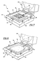
- FIG. 6 is a perspective view of a mold having a lower mold portion and an upper mold portion used in forming the seat cushion of the seat assembly of FIG. 1 and shows the preformed cover sheet of the seat cushion member preparatory to its positioning within the cavity of the lower mold portion;
- FIG. 7 shows the pre-formed cover sheet of the seat cushion located within the lower mold portion and also shows the heating element of FIG. 3 located in the buttocks area of the cover sheet within the cavity of the lower mold portion prior to the pouring of a liquid foam material into the mold;
- FIG. 8 shows the liquid foam material covering the heating element prior to the closing of the mold after which the mold is closed and the liquid foam material is molded to form the seat cushion of FIGS. 1 and 2;
- FIG. 9 is an enlargement of the portion circled and indicated by the letter “A” and shows in detail the construction of the double faced adhesive tape applied to the lower surface of the carrier member of the heating element.
- a vehicle seat assembly 10 comprising a seat cushion member 12 and a seat back member 14 .
- the seat cushion member 12 includes a heating element 16 , made in accordance with the invention, that is located in the buttocks support portion 18 of the seat cushion member 12 and serves to heat the buttocks of an occupant sitting in the seat assembly 10 .
- the core portion 20 of the seat cushion member 12 is made of a foam material, such as polyurethane foam, which in this case, is shown securely bonded through the heating element 16 to the inner surface 22 of an outer cover sheet 24 .
- the outer cover sheet 24 takes the form of a thin plastisol skin, such as vinyl plastisol, vinyl drysol, butadiene styrene or other known foam impermeable material. If desired, the cover sheet 24 can be a fabric material having a plastic backing so as to render it impermeable to the foam material which will ultimately constitute the core portion 20 of the seat cushion 12 . As will be more fully described hereinafter, the seat cushion 12 is made in its entirety in a mold cavity which is configured so as to form the seat cushion 12 shown with a pair of laterally spaced raised side sections 26 and 28 and a raised front section 30 , all of which define the recessed buttocks support portion 18 .
- a thin plastisol skin such as vinyl plastisol, vinyl drysol, butadiene styrene or other known foam impermeable material.
- the cover sheet 24 can be a fabric material having a plastic backing so as to render it impermeable to the foam material which will ultimately constitute the core portion 20 of the
- the heating element 16 is embedded in its entirety within the foam core portion 20 of the seat cushion member 12 in the area of the buttocks support portion 18 . More specifically and as seen in FIGS. 3 and 4, the heating element 16 comprises a generally rectangular carrier member 32 in the form of a net-like reticulated foam having a network of open cells throughout its entire flexible body.
- the carrier member 32 as seen in FIG. 3 and 5, has a pair of spaced parallel surfaces, namely, an upper planar surface 34 and a lower planar surface 36 .
- the upper surface 34 as seen in FIGS.
- the resistance wire 38 serves to fixedly support an electric resistance wire 38 which has a pair of ends 40 and 42 , each of which is respectively connected by a connector 44 to conductors 46 and 48 located in an electric cable 50 .
- the resistance wire 38 is arranged in a zig-zag pattern in three substantially parallel rows so as to cover most of the area of the upper surface 34 of the carrier member 32 .
- the straight section 52 of each of the loops of the resistance wire 38 forming the zig-zag arrangement is connected by a hot-melt adhesive to one or more web portions of the carrier member 32 .
- a thermostat 56 is provided on the upper surface 34 of the carrier member 32 at one side thereof midway of the adjacent row of the resistance wire 38 and serves to sense the temperature of the heating element 16 .
- the thermostat 56 controls the time when the resistance wire 38 is energized so as to provide a substantially uniform heat to the occupant of the seat assembly 10 .
- each end of the two conductors leading to the thermostat 56 are connected through a connector to one end of a pair of conductors located in the electrical cable 50 .
- the conductors leading to the thermostat 56 are secured to the webs of the carrier member 32 by a hot-melt adhesive 54 .
- the electric cable 50 connects electrically through suitable switch and control means with the electrical power of the vehicle so as to provide electricity to both the resistance wire 38 an the thermostat 56 when it is desired by the occupant of the seat assembly 10 .
- the webs along the entire lower surface 36 of the carrier member 32 are bonded to one face of a double-faced adhesive transfer tape 58 .
- the tape 58 is of the same rectangular shape as that of the carrier member 32 and is coextensive with the lower surface 36 thereof.
- the tape 58 has a layer of pressure sensitive adhesive 58 ′ coated on opposed sides of a scrim 58 ′′ made of a woven synthetic fiber.
- a specially treated paper liner 59 covers the entire lower face of the tape 58 and is removable therefrom without disturbing the adhesive adhering to the lower face of the tape 58 .
- the liner 59 is removed to expose the lower face of the tape 58 prior to the heating element 16 being incorporated into the seat cushion 12 .
- the tape 58 serves as a connector for maintaining the carrier member 32 in a fixed position during the molding process used in making the seat cushion member 12 .
- a two piece mold 60 as seen in FIG. 6, is provided comprising an upper mold portion 62 and a lower mold portion 64 .
- the lower mold portion 64 is formed with a cavity 66 which conforms in shape to the upper part, as seen in FIG. 1, of the seat cushion member 12 while the upper mold portion 62 is provided with a cavity 68 which conforms to the bottom part of the seat cushion member 12 .
- the upper mold portion 62 is pivotally connected to the lower mold portion 64 and is adapted to pivot downwardly onto the lower mold portion 64 so that the cavities 66 and 68 of the upper and lower mold portions 62 and 64 , respectively, register with each other.
- the cover sheet 24 of the seat cushion member 12 is provided as an integral part of the sheet 70 .
- Pre-forming of materials of this type is well known to those skilled in the art of in-place molding of articles. Accordingly, a description of the pre-forming process for achieving the configuration of the cover sheet 24 in the sheet 70 shall not be described in detail herein.
- the sheet 70 is positioned on the lower mold portion 64 with the cover sheet 24 located in the cavity 66 , as seen in FIG. 7 .
- the extremities of the sheet 70 surrounding the cover sheet 24 are held in place by a generally square open frame member 74 made of metal that is secured to the body of the lower mold portion 64 by a plurality of clamps 76 .
- the liner 59 is removed from the tape 58 by peeling the liner 59 off of the lower face of the tape 58 .
- the heating element 16 is then placed in the area of the buttocks support portion 18 with exposed side of the adhesive 58 ′ of the lower face of the tape 58 facing downwardly towards the inner surface 22 of the cover sheet 24 .
- the exposed adhesive 58 ′ on the lower face of the tape 58 contacts the inner surface 22 of the cover sheet 24 and adhesively secures the heating element 16 in a fixed position relative to the cover sheet 24 .
- the entire heating element 16 should be manually pressed downwardly to insure that the adhesive on the lower face of the tape 58 bonds firmly with the inner surface 22 of the cover sheet 24 .
- the cable 50 should be positioned as seen in FIG.
- the liquid urethane foam material 78 is poured into the mold to cover the heating element 16 as seen in FIGS. 7 and 8 so that the entire exposed portion of the heating element 16 is encapsulated within the liquid urethane foam.
- the upper mold portion 62 pivoted downwardly to close the mold 60 to cause the liquid foam material 78 to expand and cure and form the foam core portion 20 of the seat cushion member 12 .
- the mold 60 is then opened, the cured article removed from the lower mold portion 64 , and the extremities of the sheet 70 are trimmed so as to provide the seat cushion member 12 seen in FIGS. 1 and 2.
- the carrier member 32 contains a multiplicity of open cells interconnected by thin web sections
- the cured foam expands within the cells of the carrier member 32 and bonds to the inner face of the tape 58 in contact with the surface 36 of the carrier member 32 .
- a seat cushion 12 of the type described above was made using a heating element 16 in which the carrier member 32 was a reticulated polyurethane sheet purchased from New Dimension Industries, One State Street, Moonachie, N.J. 07074-1402.
- the carrier member 32 was of uniform thickness measuring approximately one quarter inch (the distance between surfaces 34 and 36 ) and was identified by New Dimension Industries as “NSV4 Charcoal 0.25 ⁇ 14 ⁇ 18”.
- the New Dimension Industries product specification sheet identifies the carrier member 32 as “Reticulated Polyurethane Ester Filter Foam S-04”.
- the specification sheet identifies the properties and values of such sheet as follows:
- the resistance wire 38 that can be used with the heating element 16 can be purchased from Springfield Wire Inc., 243 Cottage Street, Box 638, Springfield, Mass. 01102-0638. and should have a resistance of 226 plus-or-minus 5% Ohm/km with an operating temperature of ⁇ 30 degrees Centigrade to plus 105 degrees Centigrade.
- the hot melt adhesive 54 used for holding the resistance wire 38 and the thermostat 56 in place on the carrier member 32 was purchased from Hot Melt Technologies, Inc., 1723 West Hamlin Road, P.O. Box 80067, Rochester, Mich. 48308 and was identified as Product Number 702. The adhesive 54 was applied with a spray gun so as to provide an open cell type bond with the webs of the carrier member 32 .
- the double-faced transfer tape 58 was made by Compac Industries, Inc., Industrial Tape Division, 150 Fieldcrest Avenue, Edison, N.J. 08837.
- the tape 58 is a high tack acrylic adhesive tape coated on both sides of a synthetic fiber netting serving as a scrim reinforcement and is supplied with a moisture stable liner 59 of 50 lbs. basis weight.
- the tape 58 is identified by Compac Industries, Inc. “Net Bond 20”.
- Another tape that can be used successfully for bonding the carrier member 32 to a seat cushion member cover sheet is made by the Industrial Tape and Specialties Division of Minnesota Mining and Manufacturing Company (3M) located at 3M Center Building 220-7E-01, St. Paul, Minn. 55144-1000.
- the 3M tape is identified as 950 Tape having an A-60 adhesive which is a medium firm acrylic pressure-sensitive adhesive system.
- the liner of the 3M tape is tan paper having an approximate thickness of 0.10 mm while the 3M tape only has a thickness of 0.13 mm.
- Another form of tape that can be used is a polyurethane film with an adhesive applied to opposed sides of the film. This form of tape was made experimentally by coating the opposed sides of the film with adhesives made by Adchem Corporation, 1852 Old Country Road, Riverhead, N.Y. 11901. The adhesive coating on one side of the film was identified as No. 5370 and the adhesive on the other side of the film was identified as No. 7332. The No.
- the thermostat 56 which forms a part of the heating element 16 was purchased from Portage Electric Products, Inc., 7700 Freedom Ave. N.W., North Canton, Ohio 44720.
- the thermostat 56 is identified by Portage Electric Products as Part No. C-102651, Model J and is a bi-metal snap action thermostat.
- the heating element 16 when using a tape having a film or scrim as a reinforcement member, such film or scrim should be flexible in the sense that it is capable of being stretched sideways. This is important so that once the heating element 16 is embedded within the foam of the seat cushion member 12 and an occupant is seated in the seat assembly 10 , the heating element 16 substantially conforms in shape to the configuration of the buttocks of the occupant.
- the tape 58 along with the attached carrier member 32 can stretch, move laterally and downwardly together with the foam material of the seat cushion member 12 when the weight of the occupant is applied by the buttocks of the occupant to the buttocks support portion 18 of the seat cushion member 12 . This provides a softness to the buttocks support portion 18 permitting the buttocks of the seat occupant to have a comfortable seating effect without detecting any hardness in the support portion 18 of the seat cushion member 12 .
- the seat cushion member 12 was successfully made without any part of the heating element 16 being visible to an observer or outlined in the buttocks support portion 18 of the seat cushion member 12 . Moreover, when an occupant sits in the seat assembly 10 , there is no feel of the resistance wires 38 or of the heating element 16 through the person's buttocks.
- a fabric material backed with a plastic coating that rendered the fabric impermeable to the foam was used.
- the fabric material was pre-formed to provide the configuration of the seat cushion member, placed in a mold such as mold 60 , and afterwards the heating element 16 was positioned in the mold as described above.
- the liquid polyurethane foam material was poured in the area of the heating element 16 making certain that the entire exposed portion of the heating element 16 is covered with the liquid foam material, the mold was closed, and the foam material was allowed to cure to form the seat cushion member 12 .
- the preformed fabric cover sheet used was made by Bayer Company located at Routes 5 & 10, P.O. Box 186, South Deerfield, Mass. 01373. Such cover sheet was identified by Bayer Company as part PT 9611-Deerfield Urethane.
- the foam material used to make the core of the seat cushion was a polyurethane foam having a density of 2.8 to 3 pounds per cubic foot.
- the heating element 16 is shown as being incorporated only in the seat cushion member 12 of the seat assembly 10 . It should be apparent that the heating element 16 can equally as well be incorporated into the seat back member 14 and have the seat back member 14 formed utilizing a process such as described in connection with the seat cushion member 12 . Also, the heating element 16 is shown and described as having the double-faced adhesive tape 58 bonded to the carrier member 32 . By so doing, the heating element 16 is a complete assembly ready for instant positioning onto the inner surface 22 of the cover sheet. 24 . It should be apparent, however, that if desired, the double-faced adhesive tape 58 could be a separate part of the carrier member 32 rather than have it initially bonded, as seen in FIG.
- the tape 58 by itself, could be applied directly to the inner surface 22 in the buttocks support section 18 of the cover sheet 24 .
- the liner 59 would be removed and the carrier 32 , together with the secured wire 38 and thermostat 56 would then be positioned onto the tape 58 so as to cause the lower surface 36 of the carrier member 32 to be bonded to the exposed adhesive face of the tape 58 .
- the tape 58 does not necessarily need to be coextensive with the carrier member 32 . Instead, wide strips of the tape 58 together with the liner 59 can be applied to the surface 34 of the carrier member 32 along the rows containing the zig-zag wire 38 . Also, rather than using resistance wires, one could substitute electrically conductive pure carbon elements which could be secured to the upper surface 34 of the carrier member 32 . Such changes and modifications are contemplated by the inventors and they do not wish to be limited except by the scope of the appended claims.
Abstract
A heating element that can be incorporated into a molded foam article closely adjacent to the outer cover sheet without showing any evidence that a heating element is encapsulated within the foam portion of the article and provides essentially the same relatively softness and “feel” that would be obtained if the heating element was not part of the article.
Description
This invention relates to vehicle seats and more particularly concerns an electric heating element for a vehicle seat in which the trim cover is integrally affixed to a foam cushion member.
It is well known to have a built-in heating element for providing heat to the body of the occupant of the driver seat and/or the passenger seat of a motor vehicle. The heat is provided by electric current supplied through a conductor having suitable resistivity that ensures the desired amount of heat from the conductor. The conductor, in the form of a resistance wire, is located on a layer of textile or a plastic material to provide a carrier in the form of a planar or flat sheet. The resistance wire is fixed in position on the carrier by stitching means or by an adhesive and, afterwards, positioned between various layers of material to form the heating element which then can be incorporated into a seat. In this regard, the heating element can be sandwiched between a top cover member of leather, fabric or plastic material and the foam rubber core portion or padding of the seat.
Seats provided for vehicles used for material handling, earthmoving, or lawn cutting are normally fabricated utilizing an in-mold forming process to reduce the cost of the seat. This type of process provides a seat having a core made of a plastic foam, such as polyurethane foam, that is bonded to an outer decorative cover sheet or skin during the molding process. In the practice of such process, a properly shaped mold cavity is lined with a thin plastic or fabric skin after which liquid polyurethane is poured onto the skin to form an integral seat cushion or seat back. Various attempts have been made to provide a relatively inexpensive seat of this type that would have a heating element incorporated between the skin of the article and the foam layer. In most cases, such attempts have resulted in the configuration of the heating element and/or the conductor being outlined in the cover sheet and, therefore, not acceptable from an aesthetic standpoint. Obviously, if the heating element. could be spaced from the skin a certain distance, maintained in such position, and completely encapsulated in the foam during the molding operation, the “reading” of or outline of the heating element would not be visible to the observer.
There has also been the problem in providing a comfortable “feel” to the buttocks of a seat occupant when seated in a seat assembly having a heating element as a part of the seat structure. Inasmuch as the heating element needs to be positioned relatively close to the outer skin of a seat member and becomes an integral part of the foam structure, it stands to reason that the heating element should be designed and constructed so that it does not take away from the softness and comfort of the seat. In other words, not only should the heating element within the seat not be detectable from an appearance standpoint but, in addition, the heating element should not cause the seat to provide any substantially less comfort when occupied than would be attainable if the heating element was not a part of the seat.
Accordingly, one object of the present invention is to provide a new and improved heating element that can be incorporated into a molded foam article closely adjacent to the outer cover sheet without showing any evidence that a heating element is encapsulated within the foam portion of the article and provides essentially the same relatively softness and “feel” that would be obtained if the heating element was not part of the article.
Another object of the present invention is to provide a new and improved heating element which can be positioned relatively close to the outer skin of a seat member and permit the occupant of the seat member to have a comfortable and relatively soft seating area without detecting any hardness or the “feel” of the heating element through his/her buttocks when sitting in the seat member.
A further object of the present invention is to provide a new and improved heating element for a seat member formed as a molded foam article that includes a porous carrier member having resistance wires attached to one side thereof and that serves as a spacer for preventing the heating element and/or the resistance wires from being outlined or in the outer skin of the seat member.
A still further object of the present invention is to provide a new and improved heating element for a seat member formed as a molded foam article that is held to the skin of the seat member in a fixed position during the molding operation so as to insure that the heating element is completely embedded within the foam and is substantially uniformly spaced from the outer skin of the seat member.
A still further object of the present invention is to provide a new and improved method of incorporating a heating element within a molded foam seat member so that it is not evident that a heating element is encapsulated within the article and the heating element is maintained uniformly closely adjacent to the outer skin of the article so as to effectively transfer heat to the occupant of the seat member and provide a relatively soft “feel” to the buttocks of the occupant.
The above and other objects of the present invention are realized in accordance with the present invention by providing a heating element for an in-place foam molded seat assembly having a seat cushion member and a seat back member each of which has the foam core thereof integrally formed with the outer cover sheet. More specifically and in the preferred form, the heating element comprises a generally rectangular carrier member having an open-cell reticulated plastic structure provided with a pair of spaced substantially parallel planar surfaces. An electric conductor in the form of a resistance wire is secured to one of the surfaces of the carrier member in a zig-zag pattern and in a plurality of spaced rows so as to cover substantially the entire area of the carrier member. In addition, in the preferred form, a double-faced adhesive tape incorporating a scrim as a reinforcement member is provided on the other of the pair of surfaces of the carrier member. The tape is adapted to connect the carrier member to the inner surface of the cover sheet so as to maintain the resistance wire spaced from and in a fixed position relative to the inner surface of the cover sheet during the molding of the seat member.
Other objects and advantages of the present invention will be apparent from the following detailed description when taken with the drawings in which:
FIG. 1 is a perspective view of a molded foam seat assembly in which the seat cushion member incorporates a heating element made in accordance with the present invention;
FIG. 2 is an enlarged cross sectional view taken on line 2—2 of FIG. 1 showing the heating element located with its resistance wires substantially uniformly spaced from the cover sheet of the seat cushion member and completed embedded within the foam material thereof;
FIG. 3 is a perspective view of the heating element prior to being incorporated into the cavity of a mold for forming the seat cushion member seen in FIG. 1;
FIG. 4 is an enlarged plan view of a portion of the heating element seen in FIG. 3 showing the manner that the resistance wire is secured to the upper surface of the carrier member of the heating element;
FIG. 5 is a sectional view taken on line 5—5 of FIG. 4;
FIG. 6 is a perspective view of a mold having a lower mold portion and an upper mold portion used in forming the seat cushion of the seat assembly of FIG. 1 and shows the preformed cover sheet of the seat cushion member preparatory to its positioning within the cavity of the lower mold portion;
FIG. 7 shows the pre-formed cover sheet of the seat cushion located within the lower mold portion and also shows the heating element of FIG. 3 located in the buttocks area of the cover sheet within the cavity of the lower mold portion prior to the pouring of a liquid foam material into the mold;
FIG. 8 shows the liquid foam material covering the heating element prior to the closing of the mold after which the mold is closed and the liquid foam material is molded to form the seat cushion of FIGS. 1 and 2; and
FIG. 9 is an enlargement of the portion circled and indicated by the letter “A” and shows in detail the construction of the double faced adhesive tape applied to the lower surface of the carrier member of the heating element.
Referring to the drawings and more particularly to FIGS. 1 and 2 thereof, a vehicle seat assembly 10 is shown comprising a seat cushion member 12 and a seat back member 14. The seat cushion member 12 includes a heating element 16, made in accordance with the invention, that is located in the buttocks support portion 18 of the seat cushion member 12 and serves to heat the buttocks of an occupant sitting in the seat assembly 10. As best seen in FIG. 2, the core portion 20 of the seat cushion member 12 is made of a foam material, such as polyurethane foam, which in this case, is shown securely bonded through the heating element 16 to the inner surface 22 of an outer cover sheet 24. The outer cover sheet 24 takes the form of a thin plastisol skin, such as vinyl plastisol, vinyl drysol, butadiene styrene or other known foam impermeable material. If desired, the cover sheet 24 can be a fabric material having a plastic backing so as to render it impermeable to the foam material which will ultimately constitute the core portion 20 of the seat cushion 12. As will be more fully described hereinafter, the seat cushion 12 is made in its entirety in a mold cavity which is configured so as to form the seat cushion 12 shown with a pair of laterally spaced raised side sections 26 and 28 and a raised front section 30, all of which define the recessed buttocks support portion 18.
As seen in FIG. 2, the heating element 16 is embedded in its entirety within the foam core portion 20 of the seat cushion member 12 in the area of the buttocks support portion 18. More specifically and as seen in FIGS. 3 and 4, the heating element 16 comprises a generally rectangular carrier member 32 in the form of a net-like reticulated foam having a network of open cells throughout its entire flexible body. The carrier member 32, as seen in FIG. 3 and 5, has a pair of spaced parallel surfaces, namely, an upper planar surface 34 and a lower planar surface 36. The upper surface 34, as seen in FIGS. 3 and 4, serves to fixedly support an electric resistance wire 38 which has a pair of ends 40 and 42, each of which is respectively connected by a connector 44 to conductors 46 and 48 located in an electric cable 50. The resistance wire 38 is arranged in a zig-zag pattern in three substantially parallel rows so as to cover most of the area of the upper surface 34 of the carrier member 32. As best seen in FIG. 4, the straight section 52 of each of the loops of the resistance wire 38 forming the zig-zag arrangement is connected by a hot-melt adhesive to one or more web portions of the carrier member 32.
As seen in FIG. 3, a thermostat 56 is provided on the upper surface 34 of the carrier member 32 at one side thereof midway of the adjacent row of the resistance wire 38 and serves to sense the temperature of the heating element 16. The thermostat 56 controls the time when the resistance wire 38 is energized so as to provide a substantially uniform heat to the occupant of the seat assembly 10. As in the case of the two ends 40 and 42 of the resistance wire 38, each end of the two conductors leading to the thermostat 56 are connected through a connector to one end of a pair of conductors located in the electrical cable 50. Also, as in the case of the resistance wire 38, the conductors leading to the thermostat 56 are secured to the webs of the carrier member 32 by a hot-melt adhesive 54. At this juncture, it should be noted that the electric cable 50 connects electrically through suitable switch and control means with the electrical power of the vehicle so as to provide electricity to both the resistance wire 38 an the thermostat 56 when it is desired by the occupant of the seat assembly 10.
As seen in FIG. 4, the webs along the entire lower surface 36 of the carrier member 32 are bonded to one face of a double-faced adhesive transfer tape 58. The tape 58 is of the same rectangular shape as that of the carrier member 32 and is coextensive with the lower surface 36 thereof. As best seen in FIG. 9, the tape 58 has a layer of pressure sensitive adhesive 58′ coated on opposed sides of a scrim 58″ made of a woven synthetic fiber. A specially treated paper liner 59 covers the entire lower face of the tape 58 and is removable therefrom without disturbing the adhesive adhering to the lower face of the tape 58. As will be more fully explained hereinafter, the liner 59 is removed to expose the lower face of the tape 58 prior to the heating element 16 being incorporated into the seat cushion 12. In addition and as will become more apparent as the description of the present invention proceeds, the tape 58 serves as a connector for maintaining the carrier member 32 in a fixed position during the molding process used in making the seat cushion member 12.
As mentioned above, the heating element 16 described above and as seen in FIG. 2 is embedded within the foam core portion 20 of the seat cushion member 12 closely adjacent to the inner surface 22 of the cover sheet 24. In practicing the process for obtaining this result, a two piece mold 60, as seen in FIG. 6, is provided comprising an upper mold portion 62 and a lower mold portion 64. The lower mold portion 64 is formed with a cavity 66 which conforms in shape to the upper part, as seen in FIG. 1, of the seat cushion member 12 while the upper mold portion 62 is provided with a cavity 68 which conforms to the bottom part of the seat cushion member 12. The upper mold portion 62 is pivotally connected to the lower mold portion 64 and is adapted to pivot downwardly onto the lower mold portion 64 so that the cavities 66 and 68 of the upper and lower mold portions 62 and 64, respectively, register with each other.
Prior to closing the mold 60, a flat sheet 70 made of a vinyl material, such as described above, is initially pre-formed so as to have the configuration of the seat cushion member 12. In this manner, the cover sheet 24 of the seat cushion member 12 is provided as an integral part of the sheet 70. Pre-forming of materials of this type is well known to those skilled in the art of in-place molding of articles. Accordingly, a description of the pre-forming process for achieving the configuration of the cover sheet 24 in the sheet 70 shall not be described in detail herein.
Once the sheet 70 is pre-formed as seen in FIG. 6, the sheet 70 is positioned on the lower mold portion 64 with the cover sheet 24 located in the cavity 66, as seen in FIG. 7. The extremities of the sheet 70 surrounding the cover sheet 24 are held in place by a generally square open frame member 74 made of metal that is secured to the body of the lower mold portion 64 by a plurality of clamps 76. After the sheet 70 is properly located in the lower mold portion 64 and secured in place, the liner 59 is removed from the tape 58 by peeling the liner 59 off of the lower face of the tape 58. The heating element 16 is then placed in the area of the buttocks support portion 18 with exposed side of the adhesive 58′ of the lower face of the tape 58 facing downwardly towards the inner surface 22 of the cover sheet 24. As a result, the exposed adhesive 58′ on the lower face of the tape 58 contacts the inner surface 22 of the cover sheet 24 and adhesively secures the heating element 16 in a fixed position relative to the cover sheet 24. In order to have good adhesion between the tape 58 and the inner surface 22 of the cover sheet 24, the entire heating element 16 should be manually pressed downwardly to insure that the adhesive on the lower face of the tape 58 bonds firmly with the inner surface 22 of the cover sheet 24. At the same time, the cable 50 should be positioned as seen in FIG. 6 so that it extends out of the mold 60 when closed. Afterwards, the liquid urethane foam material 78 is poured into the mold to cover the heating element 16 as seen in FIGS. 7 and 8 so that the entire exposed portion of the heating element 16 is encapsulated within the liquid urethane foam. This is followed by having the upper mold portion 62 pivoted downwardly to close the mold 60 to cause the liquid foam material 78 to expand and cure and form the foam core portion 20 of the seat cushion member 12. The mold 60 is then opened, the cured article removed from the lower mold portion 64, and the extremities of the sheet 70 are trimmed so as to provide the seat cushion member 12 seen in FIGS. 1 and 2. Inasmuch as the carrier member 32 contains a multiplicity of open cells interconnected by thin web sections, the cured foam expands within the cells of the carrier member 32 and bonds to the inner face of the tape 58 in contact with the surface 36 of the carrier member 32. This results in the foam filled carrier member 32 effectively becoming a solid spacer member with the resistance wire 38 permanently substantially uniformly spaced from the inner surface 22 of the cover sheet 24. As a consequence, there is no “reading” or outline of the heating element 16 and/or the resistance wire 38 in the outer surface of the cover sheet 24 of the seat cushion member 12.
A seat cushion 12 of the type described above was made using a heating element 16 in which the carrier member 32 was a reticulated polyurethane sheet purchased from New Dimension Industries, One State Street, Moonachie, N.J. 07074-1402. The carrier member 32 was of uniform thickness measuring approximately one quarter inch (the distance between surfaces 34 and 36) and was identified by New Dimension Industries as “NSV4 Charcoal 0.25×14×18”. The New Dimension Industries product specification sheet identifies the carrier member 32 as “Reticulated Polyurethane Ester Filter Foam S-04”. The specification sheet identifies the properties and values of such sheet as follows:
| PROPERTY | VALUES |
| Cell Count | 04 pores per inch +1 |
| Density | 1.9 ± .1 lbs per cubic foot |
| 25% Compression force deflection (CFD) | 0.4 ± 1 lbs. per square |
| inch | |
| |
16 lbs per square inch |
| minimum | |
| Elongation | 170% minimum |
| Tear Strength | 4.5 lbs per square inch |
| minimum | |
| Compression set @ 50% Deflection | 15% loss maximum |
| 25% |
10% maximum |
| Compression set @ 50 |
10% maximum |
| autoclave loss | |
| Tensile strength dry heat loss | 15% maximum |
| Volumetric air flow rate | 21 ± 2 cubic feet per |
| minute | |
The resistance wire 38 that can be used with the heating element 16 can be purchased from Springfield Wire Inc., 243 Cottage Street, Box 638, Springfield, Mass. 01102-0638. and should have a resistance of 226 plus-or-minus 5% Ohm/km with an operating temperature of −30 degrees Centigrade to plus 105 degrees Centigrade. The hot melt adhesive 54 used for holding the resistance wire 38 and the thermostat 56 in place on the carrier member 32 was purchased from Hot Melt Technologies, Inc., 1723 West Hamlin Road, P.O. Box 80067, Rochester, Mich. 48308 and was identified as Product Number 702. The adhesive 54 was applied with a spray gun so as to provide an open cell type bond with the webs of the carrier member 32. The double-faced transfer tape 58 was made by Compac Industries, Inc., Industrial Tape Division, 150 Fieldcrest Avenue, Edison, N.J. 08837. The tape 58 is a high tack acrylic adhesive tape coated on both sides of a synthetic fiber netting serving as a scrim reinforcement and is supplied with a moisture stable liner 59 of 50 lbs. basis weight. The tape 58 is identified by Compac Industries, Inc. “Net Bond 20”. Another tape that can be used successfully for bonding the carrier member 32 to a seat cushion member cover sheet is made by the Industrial Tape and Specialties Division of Minnesota Mining and Manufacturing Company (3M) located at 3M Center Building 220-7E-01, St. Paul, Minn. 55144-1000. The 3M tape is identified as 950 Tape having an A-60 adhesive which is a medium firm acrylic pressure-sensitive adhesive system. The liner of the 3M tape is tan paper having an approximate thickness of 0.10 mm while the 3M tape only has a thickness of 0.13 mm. Another form of tape that can be used is a polyurethane film with an adhesive applied to opposed sides of the film. This form of tape was made experimentally by coating the opposed sides of the film with adhesives made by Adchem Corporation, 1852 Old Country Road, Riverhead, N.Y. 11901. The adhesive coating on one side of the film was identified as No. 5370 and the adhesive on the other side of the film was identified as No. 7332. The No. 5370 adhesive was applied to the side which is intended to adhere to the inner surface of the cavity in the mold. The thermostat 56 which forms a part of the heating element 16 was purchased from Portage Electric Products, Inc., 7700 Freedom Ave. N.W., North Canton, Ohio 44720. The thermostat 56 is identified by Portage Electric Products as Part No. C-102651, Model J and is a bi-metal snap action thermostat.
At this juncture, it will be noted that it has been found that when using a tape having a film or scrim as a reinforcement member, such film or scrim should be flexible in the sense that it is capable of being stretched sideways. This is important so that once the heating element 16 is embedded within the foam of the seat cushion member 12 and an occupant is seated in the seat assembly 10, the heating element 16 substantially conforms in shape to the configuration of the buttocks of the occupant. In other words, the tape 58 along with the attached carrier member 32 can stretch, move laterally and downwardly together with the foam material of the seat cushion member 12 when the weight of the occupant is applied by the buttocks of the occupant to the buttocks support portion 18 of the seat cushion member 12. This provides a softness to the buttocks support portion 18 permitting the buttocks of the seat occupant to have a comfortable seating effect without detecting any hardness in the support portion 18 of the seat cushion member 12.
Using a heating element 16 composed of the parts described above, the seat cushion member 12 was successfully made without any part of the heating element 16 being visible to an observer or outlined in the buttocks support portion 18 of the seat cushion member 12. Moreover, when an occupant sits in the seat assembly 10, there is no feel of the resistance wires 38 or of the heating element 16 through the person's buttocks. During one successful molding operation of the type described above, rather than using the sheet 70 made of a vinyl material for making the seat cushion member incorporating the heating element 16, a fabric material backed with a plastic coating that rendered the fabric impermeable to the foam was used. The fabric material was pre-formed to provide the configuration of the seat cushion member, placed in a mold such as mold 60, and afterwards the heating element 16 was positioned in the mold as described above. The liquid polyurethane foam material was poured in the area of the heating element 16 making certain that the entire exposed portion of the heating element 16 is covered with the liquid foam material, the mold was closed, and the foam material was allowed to cure to form the seat cushion member 12. The preformed fabric cover sheet used was made by Bayer Company located at Routes 5 & 10, P.O. Box 186, South Deerfield, Mass. 01373. Such cover sheet was identified by Bayer Company as part PT 9611-Deerfield Urethane. The foam material used to make the core of the seat cushion was a polyurethane foam having a density of 2.8 to 3 pounds per cubic foot.
In the above description of the present invention, the heating element 16 is shown as being incorporated only in the seat cushion member 12 of the seat assembly 10. It should be apparent that the heating element 16 can equally as well be incorporated into the seat back member 14 and have the seat back member 14 formed utilizing a process such as described in connection with the seat cushion member 12. Also, the heating element 16 is shown and described as having the double-faced adhesive tape 58 bonded to the carrier member 32. By so doing, the heating element 16 is a complete assembly ready for instant positioning onto the inner surface 22 of the cover sheet. 24. It should be apparent, however, that if desired, the double-faced adhesive tape 58 could be a separate part of the carrier member 32 rather than have it initially bonded, as seen in FIG. 5, to the lower surface 36 of the carrier member 32. Under such circumstances, the tape 58, by itself, could be applied directly to the inner surface 22 in the buttocks support section 18 of the cover sheet 24. After the tape is applied in this manner, the liner 59 would be removed and the carrier 32, together with the secured wire 38 and thermostat 56 would then be positioned onto the tape 58 so as to cause the lower surface 36 of the carrier member 32 to be bonded to the exposed adhesive face of the tape 58.
Various changes and modifications can be made in the construction of the heating element and the method described above without departing from the spirit of the invention. For example, rather than utilizing an adhesive such as the hot melt adhesive for fixing the wire 38 to the carrier member 32, other forms of adhesive have been found to work well for fixing the wire 38 to the carrier member 32, namely, Loctite Product 2651 and 3M Product 6111HT. Both of these adhesives can also be applied using a spray gun. The important consideration is to have the adhesive dry relatively quickly and serve to join the wire 38 to the web portions of the carrier member 32 in an open cell type bond which does not restrict the flow of the liquid foam into the interior of the carrier member 16 during the molding of the seat cushion member 12. Also, the tape 58 does not necessarily need to be coextensive with the carrier member 32. Instead, wide strips of the tape 58 together with the liner 59 can be applied to the surface 34 of the carrier member 32 along the rows containing the zig-zag wire 38. Also, rather than using resistance wires, one could substitute electrically conductive pure carbon elements which could be secured to the upper surface 34 of the carrier member 32. Such changes and modifications are contemplated by the inventors and they do not wish to be limited except by the scope of the appended claims.
Claims (14)
1. An electric heater for an in-place form molded seat assembly comprising a seat cushion member and a seat back member each of which has a core portion made of a plastic foam material bonded to an outer cover sheet, the heater to be encapsulated into one of the members and having a carrier member composed of a reticulated open cell flexible structure to be filled with the foam material during a molding process of one of said members, said carrier member having a pair of spaced surfaces, an electric conductor secured to one of said surfaces, and a connector for joining the other side of the surfaces of the carrier member to an inner surface of the cover sheet to hold the carrier member on the inner surface of the cover sheet to maintain the electric conductor spaced from and in a fixed position relative to the inner surface during the molding operation of one of the members.
2. The electric heater of claim 1 wherein said electric conductor is a wire provided with a pair of ends to be electrically connected to the electrical system of a vehicle.
3. The electric heater of claim 1 wherein said electric conductor is a resistance wire arranged in a zig-zag pattern to cover substantially the entire area of one of said surfaces.
4. The electric heater of claim 3 wherein said wire is secured to the webs of said carrier member by an adhesive.
5. The electric heater of claim 4 wherein said zig-zag pattern is provided in a plurality of substantially parallel rows.
6. The electric heater of claim 5 wherein said upper surface supports a thermostat for sensing the temperature of said electric heater.
7. The electric heater of claim 6 wherein said electric conductor is a wire provided with a pair of ends and said pair of ends of said conductor and said thermostat are electrically connected through a cable to the electrical system of a vehicle.
8. The electric heater of claim 1 wherein said electric conductor is secured to one of said surfaces of said carrier member by plastic welds.
9. The electric heater of claim 1 wherein said connector is a double-faced adhesive tape.
10. The electric heater of claim 1 wherein said connector is a double-faced adhesive tape having a scrim as a reinforcement member.
11. An electric heater for an in-place foam molded seat cushion member having an integrally formed outer cover, said heater comprising a carrier member having a flexible open-cell reticulated plastic structure to be filled with liquid foam during the molding process, the carrier member being provided with spaced and upper and lower substantially planar surfaces, an electric conductor secured to the upper surface and covering substantially the entire area of the upper surface, and an adhesive located on the lower surface of said carrier member for bonding the carrier member to the inner surface of the outer cover to maintain the electric conductor spaced from and in a fixed position relative to the inner surface during the molding operation of the seat cushion member.
12. The electric heater of claim 11 wherein said adhesive includes a double-faced adhesive tape is provided with scrim as a reinforcing member, and a paper liner on one face of said tape to be removed prior to the heater being incorporated into said seat cushion member.
13. The electric heater of claim 11 wherein said electric conductor is secured to said upper surface of said carrier member by a plurality of plastic welds.
14. The heater of claim 11 wherein said zig-zag pattern is provided in a plurality of substantially parallel rows.
Priority Applications (4)
| Application Number | Priority Date | Filing Date | Title |
|---|---|---|---|
| US09/804,423 US6489595B1 (en) | 2001-03-12 | 2001-03-12 | Electric heater for a seat assembly |
| PCT/US2002/004798 WO2002074016A1 (en) | 2001-03-12 | 2002-02-19 | Electric heater for a seat assembly |
| CA002440019A CA2440019C (en) | 2001-03-12 | 2002-02-19 | Electric heater for a seat assembly |
| US10/175,485 US7131187B2 (en) | 2001-03-12 | 2002-06-19 | Method of making a heater element for a seat assembly |
Applications Claiming Priority (1)
| Application Number | Priority Date | Filing Date | Title |
|---|---|---|---|
| US09/804,423 US6489595B1 (en) | 2001-03-12 | 2001-03-12 | Electric heater for a seat assembly |
Related Child Applications (1)
| Application Number | Title | Priority Date | Filing Date |
|---|---|---|---|
| US10/175,485 Division US7131187B2 (en) | 2001-03-12 | 2002-06-19 | Method of making a heater element for a seat assembly |
Publications (2)
| Publication Number | Publication Date |
|---|---|
| US20020170902A1 US20020170902A1 (en) | 2002-11-21 |
| US6489595B1 true US6489595B1 (en) | 2002-12-03 |
Family
ID=25188944
Family Applications (2)
| Application Number | Title | Priority Date | Filing Date |
|---|---|---|---|
| US09/804,423 Expired - Lifetime US6489595B1 (en) | 2001-03-12 | 2001-03-12 | Electric heater for a seat assembly |
| US10/175,485 Expired - Lifetime US7131187B2 (en) | 2001-03-12 | 2002-06-19 | Method of making a heater element for a seat assembly |
Family Applications After (1)
| Application Number | Title | Priority Date | Filing Date |
|---|---|---|---|
| US10/175,485 Expired - Lifetime US7131187B2 (en) | 2001-03-12 | 2002-06-19 | Method of making a heater element for a seat assembly |
Country Status (3)
| Country | Link |
|---|---|
| US (2) | US6489595B1 (en) |
| CA (1) | CA2440019C (en) |
| WO (1) | WO2002074016A1 (en) |
Cited By (14)
| Publication number | Priority date | Publication date | Assignee | Title |
|---|---|---|---|---|
| US20040060926A1 (en) * | 2001-09-14 | 2004-04-01 | Michael Weiss | Electric heating device comprising a coated heat conductor |
| US6792671B1 (en) * | 1999-09-16 | 2004-09-21 | Kongsberg Automotive Ab | Method for manufacturing and application of heating element for heating in a vehicle |
| US20050199611A1 (en) * | 2002-11-15 | 2005-09-15 | W.E.T. Automotive Systems Ag | Covered conductor and heater formed therewith |
| US20050252904A1 (en) * | 2004-05-11 | 2005-11-17 | Grabowski Brian M | Heated delivery system |
| US20070245760A1 (en) * | 2006-04-20 | 2007-10-25 | W.E.T Automotive Ag | Devices for air conditioning, detecting, and seating |
| US20080238159A1 (en) * | 2007-03-26 | 2008-10-02 | Parnis William R | Heater system for an aircraft seat |
| US20130249258A1 (en) * | 2012-03-22 | 2013-09-26 | Lear Corporation | Seat assembly having a heater wire and a method of manufacture |
| US20140109314A1 (en) * | 2011-05-23 | 2014-04-24 | Koninklijke Philips N.V. | Temperature-controlled multi-zone mattress-style support |
| US20160152111A1 (en) * | 2014-11-21 | 2016-06-02 | Kongsberg Automotive Ab | Heating Device For A Seat Heater Of A Motor Vehicle |
| US9963056B2 (en) * | 2001-09-20 | 2018-05-08 | Kurabe Industrial Co., Ltd. | Seat heater and a manufacturing method of seat heater |
| US10065543B2 (en) * | 2015-10-01 | 2018-09-04 | Kongsberg Automotive Ab | Heating and ventilation inlay for a vehicle seat |
| US20180257524A1 (en) * | 2014-11-21 | 2018-09-13 | Kongsberg Automotive Ab | Heating Device For A Seat Heater Of A Motor Vehicle |
| US20190077220A1 (en) * | 2017-09-11 | 2019-03-14 | I.G. Bauerhin Gmbh | Heating element for user-touchable areas in a vehicle and method for producing such a heating element |
| US20190208914A1 (en) * | 2018-01-08 | 2019-07-11 | Tesla, Inc. | Skin-foam architecture for seating |
Families Citing this family (32)
| Publication number | Priority date | Publication date | Assignee | Title |
|---|---|---|---|---|
| FI5838U1 (en) * | 2002-03-08 | 2003-06-30 | Nokia Corp | Shell |
| US6857697B2 (en) * | 2002-08-29 | 2005-02-22 | W.E.T. Automotive Systems Ag | Automotive vehicle seating comfort system |
| US6710303B1 (en) * | 2002-11-13 | 2004-03-23 | W.E.T. Automotive Systems Ag | Intermediate electrical connecting device for seat-heating systems |
| US7695062B2 (en) * | 2003-03-17 | 2010-04-13 | W.E.T. Automotive Systems Ag | Device for receiving functional elements |
| SE528332C2 (en) * | 2004-09-16 | 2006-10-24 | Kongsberg Automotive Ab | Heated cushion for vehicle seat has fastening materials provided on opposing main surfaces of upper and lower portions for engagement with each other to enclose and fix heating coil within cushion |
| DE102005002693B3 (en) * | 2005-01-19 | 2006-09-14 | F. S. Fehrer Automotive Foam Gmbh | Upholstered element with seat heating |
| US7178866B1 (en) * | 2005-12-22 | 2007-02-20 | Scott Steven J | Open-air vehicle seats with embedded heating elements |
| US9161393B2 (en) * | 2006-10-04 | 2015-10-13 | T+Ink, Inc. | Heated textiles and methods of making the same |
| US8008606B2 (en) * | 2006-10-04 | 2011-08-30 | T-Ink, Inc. | Composite heating element with an integrated switch |
| US8680440B2 (en) * | 2007-09-14 | 2014-03-25 | T-Ink, Inc. | Control circuit for controlling heating element power |
| FR2922497A1 (en) * | 2007-10-23 | 2009-04-24 | Cera | Seat trim cover for motor vehicle, has complex coating format provided with layer of coating material, sub-layer, and heating sheet, where heating sheet is placed between layer of coating material and sub-layer |
| US20100032998A1 (en) * | 2008-08-05 | 2010-02-11 | Michael Eckman | Portable collapsible camp chair with heated seat and back |
| US8979192B2 (en) | 2008-08-05 | 2015-03-17 | Timothy R. Miller | Portable collapsible camp chair with heated seat and back |
| US20100089894A1 (en) * | 2008-10-14 | 2010-04-15 | Simon Nicholas Richmond | Heating Apparatus |
| US8388056B2 (en) * | 2009-05-08 | 2013-03-05 | ReAnna Gayle Smith | Heated collapsible article of furniture |
| US8011727B1 (en) * | 2009-11-03 | 2011-09-06 | Martinez Yesenia C | Thermal child seat blanket apparatus |
| ES1076120Y (en) * | 2011-12-07 | 2012-05-08 | Nad S L | MOTORCYCLE SEAT WITH INTEGRATED HEATING RESISTANCE |
| CN104736387B (en) * | 2012-09-25 | 2018-01-02 | 佛吉亚汽车座椅有限责任公司 | Seat with thermal |
| KR101774798B1 (en) * | 2013-05-02 | 2017-09-05 | 젠썸 캐나다 유엘씨 | Liquid resistant heating element |
| FR3024683B1 (en) * | 2014-08-08 | 2018-02-23 | Faurecia Sieges D'automobile | THERMAL DEVICE FOR SEAT OF MOTOR VEHICLE |
| US10045401B2 (en) * | 2015-08-07 | 2018-08-07 | Kurabe Industrial Co., Ltd. | Heater unit and steering wheel |
| JP6761728B2 (en) * | 2015-10-30 | 2020-09-30 | 株式会社クラベ | Heater unit |
| JP6761727B2 (en) * | 2015-10-30 | 2020-09-30 | 株式会社クラベ | Heater unit |
| JP2017143015A (en) * | 2016-02-12 | 2017-08-17 | パナソニックIpマネジメント株式会社 | Local heater and seating seat including the same |
| US20180014360A1 (en) * | 2016-07-08 | 2018-01-11 | Check Corporation | Dual heating apparatus |
| US10640021B2 (en) * | 2016-11-04 | 2020-05-05 | Hyundai Dymos Incorporated | Cushion cover for ventilation seat |
| US11167673B2 (en) | 2017-07-25 | 2021-11-09 | Faurecia Automotive Seating, Llc | Vehicle seat |
| FR3069501B1 (en) | 2017-07-28 | 2019-09-06 | Cera Tsc | MATELASSURE FOR SEAT OF MOTOR VEHICLE |
| FR3071203B1 (en) * | 2017-09-21 | 2019-10-25 | Cera Tsc | AUTOMOTIVE VEHICLE SEAT MAINASSURE |
| US10875430B2 (en) | 2018-05-14 | 2020-12-29 | Lear Corporation | Vehicle interior assemblies having leather cover with electrically conductive coating |
| DE102019123952A1 (en) * | 2019-09-06 | 2021-03-11 | Deutsches Zentrum für Luft- und Raumfahrt e.V. | Heating mat |
| WO2022225992A1 (en) * | 2021-04-20 | 2022-10-27 | Yanfeng Automotive Safety Systems Co. Ltd | Method of producing a component for a vehicle interior |
Citations (16)
| Publication number | Priority date | Publication date | Assignee | Title |
|---|---|---|---|---|
| US4044221A (en) | 1974-07-19 | 1977-08-23 | Kommanditgesellschaft Warmetechnik B. Ruthenberg Gmbh | Flexible heating element for heating seats, in particular motor vehicle seats, couches, berths or the like |
| US4697064A (en) | 1985-02-19 | 1987-09-29 | I.G. Bauerhin GmbH Electro-Technische Fabrik | Method and apparatus for heating seats electrically |
| US4793784A (en) | 1987-10-14 | 1988-12-27 | Davidson Textron Inc. | Apparatus for making foamed articles |
| US4813738A (en) | 1988-01-04 | 1989-03-21 | Tachi-S Co., Ltd. | Automotive seat with heating device |
| US4860415A (en) * | 1988-06-13 | 1989-08-29 | Hoover Universal, Inc. | Method of making a vehicle seat assembly with pour-in-place foam body |
| US4865379A (en) | 1988-02-04 | 1989-09-12 | Tachi-S Co., Ltd. | Automotive seat with heating device |
| US4869550A (en) * | 1987-02-09 | 1989-09-26 | Warme- Und Elektrotechnik B. Ruthenberg Gmbh | Flat heater for incorporation in seats of vehicles |
| US4952776A (en) | 1988-07-01 | 1990-08-28 | Automobiles Peugeot | Seat heating device in particular for an automotive vehicle |
| US4964674A (en) | 1988-03-08 | 1990-10-23 | I.G. Bauerhin Gmbh | Heated seat |
| US5002335A (en) | 1988-03-04 | 1991-03-26 | Tocksfors Verkstads Ab | Electrically heated vehicle seat and a method of manufacturing it |
| US5523664A (en) * | 1994-04-07 | 1996-06-04 | Tachi-S Co., Ltd. | System for alleviating fatigue in a seat |
| US5723845A (en) * | 1996-02-23 | 1998-03-03 | Lear Corporation | Automotive seat with co-woven heating elements |
| US5928548A (en) | 1994-07-18 | 1999-07-27 | Tocksfors Verkstads Ab | Electric cushion heater |
| US6147332A (en) * | 1996-07-12 | 2000-11-14 | Kongsberg Automotive Ab | Arrangement and method for manufacturing of a heatable seat |
| US6158815A (en) * | 1998-12-24 | 2000-12-12 | Toyo Tire & Rubber Co., Ltd. | Seat having a seat cushion including a polyurethane foam pad onto a portion of which a stretchable, nonwoven fabric is laminated |
| US6179378B1 (en) * | 1997-05-21 | 2001-01-30 | Siemens Aktiengesellschaft | Mat with a heating wire for a motor vehicle seat heater, and motor vehicle seat with such a mat |
Family Cites Families (8)
| Publication number | Priority date | Publication date | Assignee | Title |
|---|---|---|---|---|
| GB1113433A (en) | 1963-11-22 | 1968-05-15 | Thermalay Ltd | Electrically heated sheeting,covering and like materials |
| US4060710A (en) * | 1971-09-27 | 1977-11-29 | Reuter Maschinen-And Werkzeugbau Gmbh | Rigid electric surface heating element |
| DE2616855C3 (en) | 1976-04-15 | 1981-11-12 | Wacker-Chemie GmbH, 8000 München | Process for isolating organopolysiloxane elastomer as a binder-containing resistor material from surface heating resistors |
| FR2495426A1 (en) | 1980-12-03 | 1982-06-04 | Marchal Cie Ets | Flexible electric heating plate - resistance wire being formed in zigzag grid and grid covered with glass fibre matting, immersed in silicone elastomer |
| DE3117402A1 (en) | 1981-05-02 | 1982-11-18 | Becker Autoradiowerk Gmbh, 7516 Karlsbad | Electrical heating body |
| DE3333047A1 (en) | 1983-09-14 | 1985-03-21 | I.G. Bauerhin GmbH elektro-technische Fabrik, 6466 Gründau | Upholstery element which can be heated electrically |
| US4590359A (en) * | 1984-04-26 | 1986-05-20 | Moebius Ulrich | Heating for a car seat |
| DE3513909A1 (en) | 1985-04-17 | 1986-10-23 | Becker Autoradiowerk Gmbh, 7516 Karlsbad | Electric heater and process for its production |
-
2001
- 2001-03-12 US US09/804,423 patent/US6489595B1/en not_active Expired - Lifetime
-
2002
- 2002-02-19 CA CA002440019A patent/CA2440019C/en not_active Expired - Lifetime
- 2002-02-19 WO PCT/US2002/004798 patent/WO2002074016A1/en not_active Application Discontinuation
- 2002-06-19 US US10/175,485 patent/US7131187B2/en not_active Expired - Lifetime
Patent Citations (16)
| Publication number | Priority date | Publication date | Assignee | Title |
|---|---|---|---|---|
| US4044221A (en) | 1974-07-19 | 1977-08-23 | Kommanditgesellschaft Warmetechnik B. Ruthenberg Gmbh | Flexible heating element for heating seats, in particular motor vehicle seats, couches, berths or the like |
| US4697064A (en) | 1985-02-19 | 1987-09-29 | I.G. Bauerhin GmbH Electro-Technische Fabrik | Method and apparatus for heating seats electrically |
| US4869550A (en) * | 1987-02-09 | 1989-09-26 | Warme- Und Elektrotechnik B. Ruthenberg Gmbh | Flat heater for incorporation in seats of vehicles |
| US4793784A (en) | 1987-10-14 | 1988-12-27 | Davidson Textron Inc. | Apparatus for making foamed articles |
| US4813738A (en) | 1988-01-04 | 1989-03-21 | Tachi-S Co., Ltd. | Automotive seat with heating device |
| US4865379A (en) | 1988-02-04 | 1989-09-12 | Tachi-S Co., Ltd. | Automotive seat with heating device |
| US5002335A (en) | 1988-03-04 | 1991-03-26 | Tocksfors Verkstads Ab | Electrically heated vehicle seat and a method of manufacturing it |
| US4964674A (en) | 1988-03-08 | 1990-10-23 | I.G. Bauerhin Gmbh | Heated seat |
| US4860415A (en) * | 1988-06-13 | 1989-08-29 | Hoover Universal, Inc. | Method of making a vehicle seat assembly with pour-in-place foam body |
| US4952776A (en) | 1988-07-01 | 1990-08-28 | Automobiles Peugeot | Seat heating device in particular for an automotive vehicle |
| US5523664A (en) * | 1994-04-07 | 1996-06-04 | Tachi-S Co., Ltd. | System for alleviating fatigue in a seat |
| US5928548A (en) | 1994-07-18 | 1999-07-27 | Tocksfors Verkstads Ab | Electric cushion heater |
| US5723845A (en) * | 1996-02-23 | 1998-03-03 | Lear Corporation | Automotive seat with co-woven heating elements |
| US6147332A (en) * | 1996-07-12 | 2000-11-14 | Kongsberg Automotive Ab | Arrangement and method for manufacturing of a heatable seat |
| US6179378B1 (en) * | 1997-05-21 | 2001-01-30 | Siemens Aktiengesellschaft | Mat with a heating wire for a motor vehicle seat heater, and motor vehicle seat with such a mat |
| US6158815A (en) * | 1998-12-24 | 2000-12-12 | Toyo Tire & Rubber Co., Ltd. | Seat having a seat cushion including a polyurethane foam pad onto a portion of which a stretchable, nonwoven fabric is laminated |
Cited By (20)
| Publication number | Priority date | Publication date | Assignee | Title |
|---|---|---|---|---|
| US6792671B1 (en) * | 1999-09-16 | 2004-09-21 | Kongsberg Automotive Ab | Method for manufacturing and application of heating element for heating in a vehicle |
| US20040060926A1 (en) * | 2001-09-14 | 2004-04-01 | Michael Weiss | Electric heating device comprising a coated heat conductor |
| US9963056B2 (en) * | 2001-09-20 | 2018-05-08 | Kurabe Industrial Co., Ltd. | Seat heater and a manufacturing method of seat heater |
| US20050199611A1 (en) * | 2002-11-15 | 2005-09-15 | W.E.T. Automotive Systems Ag | Covered conductor and heater formed therewith |
| US7141760B2 (en) | 2002-11-15 | 2006-11-28 | W.E.T. Automotive Systems Ag | Covered conductor and heater formed therewith |
| US20050252904A1 (en) * | 2004-05-11 | 2005-11-17 | Grabowski Brian M | Heated delivery system |
| US7034254B2 (en) | 2004-05-11 | 2006-04-25 | The Scott Fetzer Company | Heated delivery system |
| US9061602B2 (en) * | 2006-04-20 | 2015-06-23 | Gentherm Gmbh | Air conditioning device for a vehicle interior component |
| US20070245760A1 (en) * | 2006-04-20 | 2007-10-25 | W.E.T Automotive Ag | Devices for air conditioning, detecting, and seating |
| US20080238159A1 (en) * | 2007-03-26 | 2008-10-02 | Parnis William R | Heater system for an aircraft seat |
| US7823967B2 (en) | 2007-03-26 | 2010-11-02 | Emteq, Inc. | Heater system for an aircraft seat |
| US20140109314A1 (en) * | 2011-05-23 | 2014-04-24 | Koninklijke Philips N.V. | Temperature-controlled multi-zone mattress-style support |
| US10820714B2 (en) * | 2011-05-23 | 2020-11-03 | Koninklijke Philips N.V. | Temperature-controlled multi-zone mattress-style support |
| US20130249258A1 (en) * | 2012-03-22 | 2013-09-26 | Lear Corporation | Seat assembly having a heater wire and a method of manufacture |
| US20160152111A1 (en) * | 2014-11-21 | 2016-06-02 | Kongsberg Automotive Ab | Heating Device For A Seat Heater Of A Motor Vehicle |
| US20180257524A1 (en) * | 2014-11-21 | 2018-09-13 | Kongsberg Automotive Ab | Heating Device For A Seat Heater Of A Motor Vehicle |
| US10065543B2 (en) * | 2015-10-01 | 2018-09-04 | Kongsberg Automotive Ab | Heating and ventilation inlay for a vehicle seat |
| US20190077220A1 (en) * | 2017-09-11 | 2019-03-14 | I.G. Bauerhin Gmbh | Heating element for user-touchable areas in a vehicle and method for producing such a heating element |
| US10960731B2 (en) * | 2017-09-11 | 2021-03-30 | I. G. Bauerhin Gmbh | Heating element for user-touchable areas in a vehicle and method for producing such a heating element |
| US20190208914A1 (en) * | 2018-01-08 | 2019-07-11 | Tesla, Inc. | Skin-foam architecture for seating |
Also Published As
| Publication number | Publication date |
|---|---|
| US7131187B2 (en) | 2006-11-07 |
| US20020185483A1 (en) | 2002-12-12 |
| CA2440019C (en) | 2008-04-29 |
| WO2002074016A1 (en) | 2002-09-19 |
| US20020170902A1 (en) | 2002-11-21 |
| CA2440019A1 (en) | 2002-09-19 |
Similar Documents
| Publication | Publication Date | Title |
|---|---|---|
| US6489595B1 (en) | Electric heater for a seat assembly | |
| US7637573B2 (en) | Automotive vehicle seating insert | |
| US6093910A (en) | Electric seat heater | |
| US4541885A (en) | Method of manufacturing a vehicle seat cover | |
| US7588288B2 (en) | Automotive vehicle seat insert | |
| KR101414463B1 (en) | Preparation method of volume seat cover for motors using heat-press forming and volume seat cover for motors prepared by the same | |
| JPH0113396B2 (en) | ||
| US11865955B2 (en) | Suspension fabric seat heating system | |
| US20110001347A1 (en) | Cushion sheet for chair and method of manufacturing the same | |
| WO1997020669A1 (en) | Multi-layered different hardness seat equipped with surface skin and production method thereof | |
| JPH05184435A (en) | Heater for vehicle seat particularly for additionally mountable seat | |
| JPH0635780Y2 (en) | Automotive door trim with heater device | |
| WO2023039122A1 (en) | Magnetic heated seat device | |
| JPH0716365Y2 (en) | Back plate of vehicle seat back | |
| CN116039473A (en) | Method of adhering a seat trim cover to a foam cushion | |
| KR100801926B1 (en) | Chair cushion sheet and the process | |
| JPH033273Y2 (en) | ||
| JPH0312289Y2 (en) | ||
| AU2003277463B8 (en) | Vehicle seat insert | |
| JPH061040Y2 (en) | Seat structure of vehicle seat | |
| JPH0325670Y2 (en) | ||
| WO2005053956A1 (en) | Trim attachment process | |
| JPH03221432A (en) | Resin seat frame and manufacture thereof | |
| JPH07137060A (en) | Cushion body and manufacture thereof | |
| JPS6243861B2 (en) |
Legal Events
| Date | Code | Title | Description |
|---|---|---|---|
| AS | Assignment |
Owner name: CHECK CORPORATION, MICHIGAN Free format text: ASSIGNMENT OF ASSIGNORS INTEREST;ASSIGNORS:CHECK, ROBERT;PARNIS, WILLIAM R.;STUEF, THOMAS A.;REEL/FRAME:012625/0815 Effective date: 20011210 |
|
| STCF | Information on status: patent grant |
Free format text: PATENTED CASE |
|
| CC | Certificate of correction | ||
| FPAY | Fee payment |
Year of fee payment: 4 |
|
| FPAY | Fee payment |
Year of fee payment: 8 |
|
| FPAY | Fee payment |
Year of fee payment: 12 |