US6493349B1 - Extended internet protocol virtual private network architectures - Google Patents
Extended internet protocol virtual private network architectures Download PDFInfo
- Publication number
- US6493349B1 US6493349B1 US09/191,142 US19114298A US6493349B1 US 6493349 B1 US6493349 B1 US 6493349B1 US 19114298 A US19114298 A US 19114298A US 6493349 B1 US6493349 B1 US 6493349B1
- Authority
- US
- United States
- Prior art keywords
- router
- vpn
- areas
- network
- assigned
- Prior art date
- Legal status (The legal status is an assumption and is not a legal conclusion. Google has not performed a legal analysis and makes no representation as to the accuracy of the status listed.)
- Expired - Lifetime
Links
Images


Classifications
-
- H—ELECTRICITY
- H04—ELECTRIC COMMUNICATION TECHNIQUE
- H04L—TRANSMISSION OF DIGITAL INFORMATION, e.g. TELEGRAPHIC COMMUNICATION
- H04L45/00—Routing or path finding of packets in data switching networks
-
- H—ELECTRICITY
- H04—ELECTRIC COMMUNICATION TECHNIQUE
- H04L—TRANSMISSION OF DIGITAL INFORMATION, e.g. TELEGRAPHIC COMMUNICATION
- H04L12/00—Data switching networks
- H04L12/28—Data switching networks characterised by path configuration, e.g. LAN [Local Area Networks] or WAN [Wide Area Networks]
- H04L12/46—Interconnection of networks
- H04L12/4641—Virtual LANs, VLANs, e.g. virtual private networks [VPN]
- H04L12/4675—Dynamic sharing of VLAN information amongst network nodes
-
- H—ELECTRICITY
- H04—ELECTRIC COMMUNICATION TECHNIQUE
- H04L—TRANSMISSION OF DIGITAL INFORMATION, e.g. TELEGRAPHIC COMMUNICATION
- H04L45/00—Routing or path finding of packets in data switching networks
- H04L45/50—Routing or path finding of packets in data switching networks using label swapping, e.g. multi-protocol label switch [MPLS]
Definitions
- the invention relates generally to the field of virtual private networks and more particularly, to partitioning shared network infrastructure into multiple distinct virtual private network areas.
- IP Internet Protocol
- IP VPN IP Virtual Private Network
- provider includes the public carrier, network operator or Internet Provider (“ISP”), or consortiums thereof, who operate the shared network infrastructure and offer the IP VPN service.
- ISP Internet Provider
- the shared network structure will also be referred to as the base network of the VPN.
- VPNs are of great interest to both providers and to their customers because they offer privacy and cost efficiency through network infrastructure sharing. There has been difficulty providing this service, however, due to address conflicts, security problems, scalability issues and performance problems.
- the present invention includes a shared network partitioned into at least two distinct areas. It includes a first router connected to a first area and configured to distribute first router VPN information across the first area.
- the first router VPN information includes a VPN identifier which is assigned to the first router.
- the system also includes a second router connected between the first area and a second area which is configured to distribute second router VPN information across the first area.
- the second router VPN information includes a VPN identifier which is assigned to the second router.
- the VPN identifier assigned to the first router is the same as the VPN identifier assigned to the second router.
- the virtual private network infrastructure includes a shared network partitioned into at least two distinct areas. It includes first router means connected to a first area for dynamically distributing first router means VPN information across the first area and second router means connected between the first area and a second area for dynamically distributing second router means VPN information across the first and second areas.
- the first and second router means VPN information includes a VPN identifier which is assigned to said first and second router means respectively.
- the VPN identifier assigned to the first router means is the same as the VPN identifier assigned to the second router means.
- the invention includes a method of configuring a virtual private network infrastructure which enables private network communications over a shared network.
- the method includes partitioning a shared network into two or more areas. It also includes connecting a virtual router between at least two of the areas and assigning at least one VPN identifier to the virtual router.
- the method includes creating a link between a first private network router and a first shared network router, such that the first shared network router is connected to a first area. It also includes assigning the same VPN identifier assigned to the virtual router to the first shared network router; and communicating the VPN identifier between the first shared network router and the virtual router.
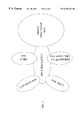
- FIG. 1 depicts a block diagram of a shared network partitioned into five areas in accordance with the invention
- FIG. 2 depicts a block diagram of a communication path across two areas depicted in FIG. 1;
- FIG. 3 depicts a block diagram of a shared network partitioned into areas in accordance with the invention illustrating different network protocols in each area.
- a VPN is a group of individual private networks logically connected through one or more shared networks.
- VPNs are formed by distributing VPN information throughout the shared network(s), and forming tunnels between VPN routers which are members of a common VPN.
- An IP VPN service includes the routing of IP network traffic by the provider over the shared network(s) based upon its IP destination address.
- Benefits of an IP VPN include simplified configuration of edge routers (also referred to herein as shared network routers and border routers), and the wide acceptance and adoption of IP service for connecting private networks to provider points of presence (POPs).
- edge routers also referred to herein as shared network routers and border routers
- POPs provider points of presence
- IP VPN services There are a number of generic operations performed in IP VPN services including: VPN membership discovery, the process by which provider nodes learn of the other nodes serving the same VPN; and tunnel establishment, the process of providing private paths across the base network for each private network's data. Both of these operations are well known and thus will not be described herein.
- VPN membership discovery the process by which provider nodes learn of the other nodes serving the same VPN
- tunnel establishment the process of providing private paths across the base network for each private network's data. Both of these operations are well known and thus will not be described herein.
- IP service participates in the private network's routing regime. Nodes in the private network exchange reachability information with nodes in the provider's network via the “stub” link reachability information exchange process. The provider nodes serving a particular VPN propagate this reachability information to each other to enable them to route the communication packets. This is the Intra VPN reachability exchange.
- VPN “areas” are formed by partitioning a provider's shared network infrastructure. Within a VPN area various VPN mechanisms (i.e. base network, tunneling, VPN membership discovery etc.) are the same. Between two or more VPN areas the VPN mechanisms can be different; although they are not required to be.
- VPN areas allow an IP VPN provider to partition the shared network based upon IP VPN implementation choices. For example, a provider may have Multi-Protocol Label Switching (MPLS) in the backbone part of the shared network but not in all regional networks (See FIG. 3 ). The Provider can operate a MPLS based IP VPN area in the backbone, as described, while using other forms of IP VPN technology (e.g.
- MPLS Multi-Protocol Label Switching
- IP over Frame Relay IP over leased lines, IP over Local Area Network Emulation (LANE), IP over IP, IP over GRE, IP over L 2 TP, IP over IPSec, IP over ethernet or any other conventional IP tunneling technology) in the regional VPN areas or it could employ one of these others as the backbone.
- LNE Local Area Network Emulation
- IP over IP IP over GRE
- IP over L 2 TP IP over L 2 TP
- IP over IPSec IP over ethernet or any other conventional IP tunneling technology
- VPN areas could be employed to cater to administrative boundaries. For example a group of network providers may band together to offer a combined IP VPN service, however each may also wish to retain control of the private networks they serve. They may enter into transit and peering agreements to offer a seamless IP VPN service within their combined geographical area of coverage. However, the service offered to private networks may also be restricted to a single VPN area in return for a lower fee collected just by the operator of that area. Each of the network operators may operate different base networks, tunnel mechanisms, etc. within their own VPN areas (As illustrated in FIG. 3 ).
- a single provider or multiple providers acting in concert could also introduce VPN areas to establish rate boundaries based on country, state, province, or some other geographic region to support charging different rates for inter-region traffic and intra-region traffic.
- Quality of Service may also vary in different VPN areas.
- a provider may wish to offer service level agreements relating to delay, packet loss etc. for IP VPN service where the parameters are different for different VPN areas. For example a provider could treat his/her shared network as one VPN area and the Internet as another area. For IP VPN traffic confined to the shared network, the provider may be able to offer fairly tight service guarantees, by means of the technologies employed, network topology and traffic engineering. But if a private network has some remote sites which could not practically connect directly to the provider's network, the provider could connect these sites to the IP VPN by setting up tunnels to them over the Internet.
- VPN areas also provide a framework for addressing traffic engineering and scalability concerns.
- the load from different VPNs can be allocated to different routers. If the routing regimes being used in a VPN provide equal cost path routing then there can be load sharing within a VPN through multiple gateway routers (also referred to as shared or border routers).
- Multiple gateway routers provide automatic resilience, and while packets are in tunnels (i.e. encapsulated), they do not have to carry expensive to process source route headers.
- any base networks can support an unlimited number of tunnels.
- the tunnel mechanism is Virtual Circuits on a base Frame Relay network the total number of tunnels will depend of the number of DLCI's that can be supported on shared Frame Relay links. Efficient use of VPN areas can reduce the number of tunnels needed, permitting the support of more VPNs, serving more private networks.
- a VR is a forwarding control process in a VBR, dedicated to one IP VPN. It participates directly in routing information exchanges with other VRs dedicated to the VPN, over tunnels of that VPN.
- the routing exchanges relate only to the IP address space of the private network.
- the routing regime used can be specific to individual VPNs (e.g. small one might use RIP while larger ones use OSPF).
- a VR may use different routing protocols on each of its interfaces. It could theoretically exchanging routing information with all of a private network's routers (e.g.
- VPN areas significantly reduce the number of peers with which VRs must exchange Intra VPN reachability information. This allows border routers to support more VPNs with less routing packet exchange overhead.
- gateway routers could become bottlenecks, this problem can be engineered away, since different VPNs can be assigned to different gateway routers.
- the resulting spreading of the load through multiple gateways may be an improvement over a single VPN area wherein the base network routing regime sent all traffic between two regions through one gateway.
- VBR VPN Border Router
- VBRs serving a single VPN may be located at the customer's location, at a POP or some other reasonable location.
- a VPN area can contain both shared and exclusive VBRs. It is a provider's choice as to whether to deploy all POP based shared VBRs, customer located exclusive VBRs or a mixture of both.
- VBR functions can also be labeled as edge, gateway or special.
- a VBR need not be dedicated to only one of these functions.
- the edge function involves the serving of one or more private networks.
- the gateway function involves attaching two or more VPN areas. They may also connect a VPN area to other types of networks.
- Special functions include: Internet Attachment (Private Network access to the Internet may be offered as an extension of IP VPN service and be implemented by a special VBR that performs firewall (and, if needed, NAT) functions), Virtual Private Dial Network Attachment (Dial-in users may be connected directly to the IP VPN, instead of terminating on a home gateway at a particular private network; i.e.
- VBR acts like a Remote Access Server or as a home gateway); and VPLS Interworking (there are many similarities between Virtual Private LAN Subnet service and IP VPN service.
- a provider may offer both, in particular some private network may connect to a VBR over virtual private LAN subnet (or even a real LAN subnet)). Minor changes in VBR edge functionality are required to handle this interworking.
- a VBR serves a particular VPN if it terminates one or more stub links to private networks of that VPN.
- a gateway VBR that straddles two or more VPN areas serves a particular VPN if it forwards traffic for that VPN between the areas.
- a provider or consortium thereof wishing to offer IP VPN service using multiple VPN areas must decide on the basis for partitioning their network and then configure VBRs to realize the desired VPN areas. If the basis for VPN areas relates to base network technology then the partitioning process will be straightforward: gateway VBRs will be deployed with separate interfaces to two or more base networks. If the deployment of multiple VPN areas is being driven by scalability or administrative domain concerns, and if the base network is common to all the VPN areas, then particular care will be needed in configuring the interfaces of gateway VBRs. An interface's type or network address may not be enough to determine which VPN area it participates in. A VPN area Identifier may need to be introduced to facilitate configuring gateway VBRs in this situation.
- Gateway VBRs may serve large numbers of VPNs. Within each VBR there may be a forwarding table for each IP VPN supported by that VBR. This information could also be located at some central location or at various centralized locations. The forwarding control process operates in the private network address space. When packets arrives at a gateway VBR the VBR will select the correct forwarding table based upon the identity of the incoming tunnel. The forwarding table will then determine the tunnel on which packets should be sent out (suitably encapsulated for the tunnel selected).
- Intra VPN reachability information being piggy backed on routing exchanges taking place in the base network and employing VRs.
- a VR sees the VRs of all other VBRs in its VPN area as neighbors. From the perspective of the IP VPN routing, all its VRs in a VPN area are a single hop from each other. VRs in different VPN areas are two or more hops away.
- the preferred embodiment employs VRs as the mechanism for constructing and maintaining forwarding tables in VBRs.
- the power of the VPN area concept is that within one IP VPN service it would permit one VPN area to disseminate intra VPN reachability information using base network routing exchange piggybacking and another area to use virtual routers.
- piggybacking may require modifying routing protocols and that there are scoping issues to address, while VRs run their routing protocols unmodified and secure.
- FIG. 1 shows a partitioning of a shared network into 5 VPN areas. Those skilled in the art will recognize that while 5 areas are illustrated, the network could be partitioned into different numbers of areas. Further, the illustrated shapes of the networks is not important.
- FIG. 2 illustrates a communication path between two private networks which traverses two VPN areas.
- Each VPN area is bordered by VBRs and contains other nodes that operate as part of the base network but are unaware of the IP VPN service because private network traffic is tunneled through them.
- tunnel is being used here to mean any mechanism that encapsulates enterprise IP packets and carries a demultiplexing identifier that VBRs use to separate out IP packets of the different VPNs: a layer 2 virtual circuit is a tunnel in this sense).
- All but the smallest of private networks will interface to the provider's network from a private router over a “stub” link.
- Some larger private networks may have multiple links, from the same or different private network routers, to the same VBR or to different VBRs.
- a private network may have stub links to VBRs in different VPN areas.
- VPNID is used in the VPN membership dissemination operation.
- this form of VPNID which we call the local VPNID, has only to be unique within a VPN area.
- any VPNID used should be unique within an Autonomous System.
- a provider whose base network spans multiple VPN areas will need to decide if the IP VPN service offered to a particular private network will be confined to a single area or span multiple VPN areas.
- the provider enables the latter by configuring VRs for the new IP VPN in gateway VBRs. These VRs will be informed of the routing regime they are to participate in and they will need a router number and/or IP address assignment from the private network IP space. If there is to be chain of trust between the VRs dedicated to the VPN (preferably) then appropriate credentials should also be administered. Finally, the VR will be configured with a local VPNID for use in each VPN area it is configured to operate in.
- the gateway VBR is able to participate in the VPN membership dissemination process with the other VBRs in each of the VPN areas it is attached to.
- the VPN membership dissemination mechanism may be different in each VPN area, but the end result is that each VR dedicated to a particular VPN (i.e. assigned the same VPNID) has enough information to establish tunnels to all other VRs of that VPN, within that VPN area.
- a VPN area specific mechanism is then used to establish tunnels between all VRs serving the particular IP VPN. All private network traffic travels across a VPN area in a single tunnel hop. Traffic traveling between VPN areas is forwarded by VRs in the gateway VBRs that have been configured to be part of the VPN.
- Each gateway VBR between stub and core could cache the VPN membership announcements that it receives on its stub side and relay them over the core. If there were a matching VPNID from another gateway VBR then both would initialize a VR, and establish a tunnel between them. The new VRs would also announce their presence on the stub network to complete the VPN tunnel connectivity.
- tunnels may be realized by GRE over a base network that is IP and in another tunnels may be realized by ATM SVCs over a base network that is ATM.
- the VRs in gateway VBRs transfer traffic between tunnels.
- VPN areas enable more complex stub link connectivities, such as multiple links from a private network to different VPN areas.
- VBRs will have to push routing hop information to the private network routers if loops and sub optimal forwarding are to be avoided.
- the most general mechanism for the VBR to learn the set of address prefixes that are reachable over the (stub) link and for the enterprise site to learn what addresses it should forward over a stub link is for the private network edge routers and the VPN VRs to participate in the same routing regime.
- Each VPN area may have a different mechanism for the dissemination of VPN membership.
- the existence of new sites need only be propagated to the VBRs within a VPN area.
- other VBRs will learn the reachability information for the new site through the routing protocol exchanges of the IP VPN.
- the VRs within a VPN area discover each other and the mesh of tunnels between them is established. VRs can then exchange routing information with their neighbors within the VPN over the tunnels.
- a gateway VR that straddles VPN areas may then convey the new routing information across the VPN area boundary, to all of its neighbors in the other VPN area.
- a private network wants to obtain an IP VPN service from a provider the provider must allocate a VPNID and then provision the stub links between a private network and one or more VBRs.
- the provider must provide a VR at each VBR that has stub links terminating on it for the new IP VPN. This involves assigning the VR an IP address, or router number, out of the private network address space, in addition to assigning IP addresses for each stub link terminating on the VR.
- a routing protocol process needs to be provided for each stub link, plus one for the tunnels that will be established between VRs.
- the provider must determine the scope of the IP VPN service, and, if it is to cross multiple VPN areas, choose gateway VBRs on which to provide VRs for VPN. With the VRs in place automatic tunnel establishment can proceed, resulting in tunnel meshes within VPN areas and the provider chosen connectivity between areas.
- each of the routing processes will discover each other by exchanging messages over the tunnels. After this, the VRs are able to forward enterprise traffic between all sites in the VPN.
- the invention efficiently attains the objects set forth above, among those made apparent from the preceding description.
- the invention provides a partitioned shared network for providing virtual private networks and methods of configuring the same.
- FIGS. 1-3 discloses a shared network which allows the implementation of separate networks over common infrastructure while providing security, scalability and performance to each network.
Abstract
Description
Claims (18)
Priority Applications (1)
| Application Number | Priority Date | Filing Date | Title |
|---|---|---|---|
| US09/191,142 US6493349B1 (en) | 1998-11-13 | 1998-11-13 | Extended internet protocol virtual private network architectures |
Applications Claiming Priority (1)
| Application Number | Priority Date | Filing Date | Title |
|---|---|---|---|
| US09/191,142 US6493349B1 (en) | 1998-11-13 | 1998-11-13 | Extended internet protocol virtual private network architectures |
Publications (1)
| Publication Number | Publication Date |
|---|---|
| US6493349B1 true US6493349B1 (en) | 2002-12-10 |
Family
ID=22704302
Family Applications (1)
| Application Number | Title | Priority Date | Filing Date |
|---|---|---|---|
| US09/191,142 Expired - Lifetime US6493349B1 (en) | 1998-11-13 | 1998-11-13 | Extended internet protocol virtual private network architectures |
Country Status (1)
| Country | Link |
|---|---|
| US (1) | US6493349B1 (en) |
Cited By (111)
| Publication number | Priority date | Publication date | Assignee | Title |
|---|---|---|---|---|
| US20020055989A1 (en) * | 2000-11-08 | 2002-05-09 | Stringer-Calvert David W.J. | Methods and apparatus for scalable, distributed management of virtual private networks |
| US20020087724A1 (en) * | 2000-12-29 | 2002-07-04 | Ragula Systems D/B/A Fatpipe Networks | Combining connections for parallel access to multiple frame relay and other private networks |
| US20020099849A1 (en) * | 2001-01-25 | 2002-07-25 | Crescent Networks, Inc. | Dense virtual router packet switching |
| US20020133549A1 (en) * | 2001-03-15 | 2002-09-19 | Warrier Ulhas S. | Generic external proxy |
| US20020154635A1 (en) * | 2001-04-23 | 2002-10-24 | Sun Microsystems, Inc. | System and method for extending private networks onto public infrastructure using supernets |
| US20030016679A1 (en) * | 2001-03-30 | 2003-01-23 | Steve Adams | Method and apparatus to perform network routing |
| US20030037163A1 (en) * | 2001-08-15 | 2003-02-20 | Atsushi Kitada | Method and system for enabling layer 2 transmission of IP data frame between user terminal and service provider |
| US20030035430A1 (en) * | 2000-10-03 | 2003-02-20 | Junaid Islam | Programmable network device |
| US20030041170A1 (en) * | 2001-08-23 | 2003-02-27 | Hiroyuki Suzuki | System providing a virtual private network service |
| WO2003027878A1 (en) * | 2001-09-28 | 2003-04-03 | Fiberlink Communications Corporation | Client-side network access polices and management applications |
| US20030088699A1 (en) * | 1999-11-04 | 2003-05-08 | James V. Luciani | System, device, and method for supporting virtual private networks in a label switched communication network |
| US20030149899A1 (en) * | 1999-01-29 | 2003-08-07 | International Business Machines Corporation | System and method for network address translation integration with IP security |
| US20030198235A1 (en) * | 1999-12-22 | 2003-10-23 | Mci Worldcom, Inc. | Method, computer program product, and apparatus for collecting service level agreement statistics in a communication network |
| US20030226013A1 (en) * | 2002-05-31 | 2003-12-04 | Sri International | Methods and apparatus for scalable distributed management of wireless virtual private networks |
| US20030233576A1 (en) * | 2002-06-13 | 2003-12-18 | Nvidia Corp. | Detection of support for security protocol and address translation integration |
| US20040076165A1 (en) * | 2002-10-22 | 2004-04-22 | Le Pennec Jean-Francois | Virtual private network based upon multi-protocol label switching adapted to measure the traffic flowing between single rate zones |
| US20040095947A1 (en) * | 1999-05-11 | 2004-05-20 | Luciani James V. | System, device, and method for supporting virtual private networks |
| US20040120257A1 (en) * | 2002-12-23 | 2004-06-24 | James Uttaro | MPLS virtual private network using dual network cores |
| US6775235B2 (en) | 2000-12-29 | 2004-08-10 | Ragula Systems | Tools and techniques for directing packets over disparate networks |
| US6778494B1 (en) * | 1999-03-10 | 2004-08-17 | Nortel Networks Limited | Label switched media gateway and network |
| US20040190532A1 (en) * | 2003-03-31 | 2004-09-30 | Naoki Oguchi | Virtual path configuration apparatus, virtual path configuration method, and computer product |
| US6813644B1 (en) * | 1998-11-18 | 2004-11-02 | Nortel Networks Limited | Distribution of reachability information in data virtual private networks |
| US20050047407A1 (en) * | 2003-08-27 | 2005-03-03 | Cosine Communications, Inc. | Heterogeneous media packet bridging |
| US20050081045A1 (en) * | 2003-08-15 | 2005-04-14 | Fiberlink Communications Corporation | System, method, apparatus and computer program product for facilitating digital communications |
| KR100485801B1 (en) * | 2002-03-07 | 2005-04-28 | 삼성전자주식회사 | Network connecting apparatus and method for offering direct connection between network devices existing different private networks |
| US6894999B1 (en) * | 2000-11-17 | 2005-05-17 | Advanced Micro Devices, Inc. | Combining VLAN tagging with other network protocols allows a user to transfer data on a network with enhanced security |
| US20050254651A1 (en) * | 2001-07-24 | 2005-11-17 | Porozni Baryy I | Wireless access system, method, signal, and computer program product |
| US20050262264A1 (en) * | 2004-05-24 | 2005-11-24 | Tatsuhiro Ando | MPLS network and architecture method thereof |
| US6982984B1 (en) * | 2001-08-28 | 2006-01-03 | Redback Networks Inc. | Method and apparatus for virtual private networks |
| US7023860B1 (en) * | 2000-01-17 | 2006-04-04 | Nortel Networks Limited | Communications network |
| US20060080421A1 (en) * | 2003-09-03 | 2006-04-13 | Sbc Knowledge Ventures, L.P. | Method and system for automating membership discovery in a distributed computer network |
| US7082140B1 (en) * | 2000-03-17 | 2006-07-25 | Nortel Networks Ltd | System, device and method for supporting a label switched path across a non-MPLS compliant segment |
| EP1684469A1 (en) * | 2005-01-24 | 2006-07-26 | Samsung Electronics Co., Ltd. | Apparatus and method for providing multiprotocol label switching (MPLS) based virtual private network (VPN) |
| US20060215698A1 (en) * | 2003-11-19 | 2006-09-28 | Amen Hamdan | Communication subsystem controlled information dissemination |
| EP1708408A1 (en) * | 2004-01-20 | 2006-10-04 | Huawei Technologies Co., Ltd. | A system and method of ensuring quality of service in virtual private network |
| US20060227786A1 (en) * | 1999-08-31 | 2006-10-12 | Science Applications International Corporation | System and Method for Interconnecting Multiple Virtual Private Networks |
| US20070055752A1 (en) * | 2005-09-08 | 2007-03-08 | Fiberlink | Dynamic network connection based on compliance |
| US7194767B1 (en) * | 2002-06-28 | 2007-03-20 | Sprint Communications Company L.P. | Screened subnet having a secured utility VLAN |
| US20070064704A1 (en) * | 2002-06-04 | 2007-03-22 | Fortinet, Inc. | Methods and systems for a distributed provider edge |
| US20070104119A1 (en) * | 2000-09-13 | 2007-05-10 | Fortinet, Inc. | System and method for managing and provisioning virtual routers |
| US20070109968A1 (en) * | 2002-06-04 | 2007-05-17 | Fortinet, Inc. | Hierarchical metering in a virtual router-based network switch |
| US20070121579A1 (en) * | 2000-09-13 | 2007-05-31 | Fortinet, Inc. | Packet routing system and method |
| US20070127382A1 (en) * | 2002-06-04 | 2007-06-07 | Fortinet, Inc. | Routing traffic through a virtual router-based network switch |
| US20070143851A1 (en) * | 2005-12-21 | 2007-06-21 | Fiberlink | Method and systems for controlling access to computing resources based on known security vulnerabilities |
| US20070143827A1 (en) * | 2005-12-21 | 2007-06-21 | Fiberlink | Methods and systems for intelligently controlling access to computing resources |
| US20070147368A1 (en) * | 2002-06-04 | 2007-06-28 | Fortinet, Inc. | Network packet steering via configurable association of processing resources and netmods or line interface ports |
| US20070177594A1 (en) * | 2006-01-30 | 2007-08-02 | Juniper Networks, Inc. | Forming equal cost multipath multicast distribution structures |
| US20070177593A1 (en) * | 2006-01-30 | 2007-08-02 | Juniper Networks, Inc. | Forming multicast distribution structures using exchanged multicast optimization data |
| US7266604B1 (en) * | 2000-03-31 | 2007-09-04 | Microsoft Corporation | Proxy network address translation |
| US7281039B1 (en) * | 1998-12-24 | 2007-10-09 | Redback Networks Inc. | Domain isolation through virtual network machines |
| US20080016389A1 (en) * | 2002-08-29 | 2008-01-17 | Fortinet, Inc. | Fault tolerant routing in a network routing system based on a passive replication approach |
| US7406034B1 (en) | 2002-04-01 | 2008-07-29 | Cisco Technology, Inc. | Methods and apparatus for fibre channel frame delivery |
| US20080222696A1 (en) * | 2004-08-16 | 2008-09-11 | Fiberlink Communications Corporation | System, Method, Apparatus, and Computer Program Product for Facilitating Digital Communications |
| US7433326B2 (en) | 2002-11-27 | 2008-10-07 | Cisco Technology, Inc. | Methods and devices for exchanging peer parameters between network devices |
| US20080259936A1 (en) * | 2002-06-04 | 2008-10-23 | Fortinet, Inc. | Service processing switch |
| US20080259934A1 (en) * | 2000-09-13 | 2008-10-23 | Fortinet, Inc. | Distributed virtual system to support managed, network-based services |
| US7499419B2 (en) | 2004-09-24 | 2009-03-03 | Fortinet, Inc. | Scalable IP-services enabled multicast forwarding with efficient resource utilization |
| US7499410B2 (en) | 2001-12-26 | 2009-03-03 | Cisco Technology, Inc. | Fibre channel switch that enables end devices in different fabrics to communicate with one another while retaining their unique fibre channel domain—IDs |
| US7519010B1 (en) | 2004-08-30 | 2009-04-14 | Juniper Networks, Inc. | Inter-autonomous system (AS) multicast virtual private networks |
| US20090097490A1 (en) * | 2003-05-08 | 2009-04-16 | Onvoy, Inc. | Communications network with converged services |
| US20090175274A1 (en) * | 2005-07-28 | 2009-07-09 | Juniper Networks, Inc. | Transmission of layer two (l2) multicast traffic over multi-protocol label switching networks |
| US7564803B1 (en) | 2005-08-29 | 2009-07-21 | Juniper Networks, Inc. | Point to multi-point label switched paths with label distribution protocol |
| US7570582B1 (en) * | 2000-07-28 | 2009-08-04 | Cisco Technology, Inc. | Method and system for routing communications among computer networks |
| US7574495B1 (en) * | 2000-09-13 | 2009-08-11 | Fortinet, Inc. | System and method for managing interworking communications protocols |
| US7580373B2 (en) | 2001-06-28 | 2009-08-25 | Fortinet, Inc. | Identifying nodes in a ring network |
| US7593324B2 (en) | 2004-10-25 | 2009-09-22 | Cisco Technology, Inc. | Graceful port shutdown protocol for fibre channel interfaces |
| US7599360B2 (en) | 2001-12-26 | 2009-10-06 | Cisco Technology, Inc. | Methods and apparatus for encapsulating a frame for transmission in a storage area network |
| US7602702B1 (en) | 2005-02-10 | 2009-10-13 | Juniper Networks, Inc | Fast reroute of traffic associated with a point to multi-point network tunnel |
| US7616637B1 (en) * | 2002-04-01 | 2009-11-10 | Cisco Technology, Inc. | Label switching in fibre channel networks |
| US7640319B1 (en) * | 2003-09-30 | 2009-12-29 | Nortel Networks Limited | Gateway shared by multiple virtual private networks |
| US7649844B2 (en) | 2004-12-29 | 2010-01-19 | Cisco Technology, Inc. | In-order fibre channel packet delivery |
| US20100057919A1 (en) * | 2008-08-27 | 2010-03-04 | At&T Intellectual Property I, L.P. | System and Method to Provide a Network Service |
| US20100124231A1 (en) * | 2008-11-14 | 2010-05-20 | Juniper Networks, Inc. | Summarization and longest-prefix match within mpls networks |
| US7738401B2 (en) * | 2005-10-20 | 2010-06-15 | At&T Intellectual Property I, L.P. | System and method for overlaying a hierarchical network design on a full mesh network |
| US7742482B1 (en) | 2006-06-30 | 2010-06-22 | Juniper Networks, Inc. | Upstream label assignment for the resource reservation protocol with traffic engineering |
| WO2010071978A1 (en) * | 2008-12-22 | 2010-07-01 | Nortel Networks Limited | A method for operating multi-domain provider ethernet networks |
| US7765581B1 (en) | 1999-12-10 | 2010-07-27 | Oracle America, Inc. | System and method for enabling scalable security in a virtual private network |
| US7769873B1 (en) | 2002-10-25 | 2010-08-03 | Juniper Networks, Inc. | Dynamically inserting filters into forwarding paths of a network device |
| US7808904B2 (en) | 2004-11-18 | 2010-10-05 | Fortinet, Inc. | Method and apparatus for managing subscriber profiles |
| US7830809B2 (en) | 2002-06-12 | 2010-11-09 | Cisco Technology, Inc. | Methods and apparatus for characterizing a route in a fibre channel fabric |
| US7839862B1 (en) | 2006-06-30 | 2010-11-23 | Juniper Networks, Inc. | Upstream label assignment for the label distribution protocol |
| US7856509B1 (en) | 2004-04-09 | 2010-12-21 | Juniper Networks, Inc. | Transparently providing layer two (L2) services across intermediate computer networks |
| US7916628B2 (en) | 2004-11-01 | 2011-03-29 | Cisco Technology, Inc. | Trunking for fabric ports in fibre channel switches and attached devices |
| US7933269B2 (en) | 2002-11-18 | 2011-04-26 | Fortinet, Inc. | Hardware-accelerated packet multicasting in a virtual routing system |
| US7936780B1 (en) | 2008-03-12 | 2011-05-03 | Juniper Networks, Inc. | Hierarchical label distribution protocol for computer networks |
| US7974201B1 (en) * | 1999-10-15 | 2011-07-05 | Cisco Technology, Inc. | Technique and apparatus for using node ID as virtual private network (VPN) identifiers |
| US7990965B1 (en) | 2005-07-28 | 2011-08-02 | Juniper Networks, Inc. | Transmission of layer two (L2) multicast traffic over multi-protocol label switching networks |
| US8051177B1 (en) | 2003-09-30 | 2011-11-01 | Genband Us Llc | Media proxy having interface to multiple virtual private networks |
| US8069233B2 (en) | 2000-09-13 | 2011-11-29 | Fortinet, Inc. | Switch management system and method |
| US8078758B1 (en) | 2003-06-05 | 2011-12-13 | Juniper Networks, Inc. | Automatic configuration of source address filters within a network device |
| US8125926B1 (en) | 2007-10-16 | 2012-02-28 | Juniper Networks, Inc. | Inter-autonomous system (AS) virtual private local area network service (VPLS) |
| US20120236844A1 (en) * | 1999-10-04 | 2012-09-20 | Rex Hester | Enabling quality voice communications from web page call control |
| US8310957B1 (en) | 2010-03-09 | 2012-11-13 | Juniper Networks, Inc. | Minimum-cost spanning trees of unicast tunnels for multicast distribution |
| US8422514B1 (en) | 2010-02-09 | 2013-04-16 | Juniper Networks, Inc. | Dynamic configuration of cross-domain pseudowires |
| US8462635B1 (en) | 2006-06-30 | 2013-06-11 | Juniper Networks, Inc. | Resource reservation protocol with traffic engineering point to multi-point label switched path hierarchy |
| US20130318345A1 (en) * | 2012-05-22 | 2013-11-28 | Harris Corporation | Multi-tunnel virtual private network |
| US8650390B2 (en) | 2000-09-13 | 2014-02-11 | Fortinet, Inc. | Tunnel interface for securing traffic over a network |
| US8660129B1 (en) | 2012-02-02 | 2014-02-25 | Cisco Technology, Inc. | Fully distributed routing over a user-configured on-demand virtual network for infrastructure-as-a-service (IaaS) on hybrid cloud networks |
| US8837479B1 (en) | 2012-06-27 | 2014-09-16 | Juniper Networks, Inc. | Fast reroute between redundant multicast streams |
| US8917729B1 (en) | 2008-12-10 | 2014-12-23 | Juniper Networks, Inc. | Fast reroute for multiple label switched paths sharing a single interface |
| US8953500B1 (en) | 2013-03-29 | 2015-02-10 | Juniper Networks, Inc. | Branch node-initiated point to multi-point label switched path signaling with centralized path computation |
| US9049148B1 (en) | 2012-09-28 | 2015-06-02 | Juniper Networks, Inc. | Dynamic forwarding plane reconfiguration in a network device |
| US9100213B1 (en) | 2011-06-08 | 2015-08-04 | Juniper Networks, Inc. | Synchronizing VPLS gateway MAC addresses |
| US9154327B1 (en) | 2011-05-27 | 2015-10-06 | Cisco Technology, Inc. | User-configured on-demand virtual layer-2 network for infrastructure-as-a-service (IaaS) on a hybrid cloud network |
| US9246838B1 (en) | 2011-05-27 | 2016-01-26 | Juniper Networks, Inc. | Label switched path setup using fast reroute bypass tunnel |
| US9806895B1 (en) | 2015-02-27 | 2017-10-31 | Juniper Networks, Inc. | Fast reroute of redundant multicast streams |
| US9860225B1 (en) * | 2014-05-15 | 2018-01-02 | Amazon Technologies, Inc. | Network directory and access service |
| US10178025B2 (en) * | 2014-11-13 | 2019-01-08 | At&T Intellectual Property I, L.P. | Methods and apparatus to route traffic in a virtual private network |
| US10284392B2 (en) | 2017-05-19 | 2019-05-07 | At&T Intellectual Property I, L.P. | Virtual private network resiliency over multiple transports |
| US10511573B2 (en) * | 1998-10-30 | 2019-12-17 | Virnetx, Inc. | Agile network protocol for secure communications using secure domain names |
| WO2023129800A1 (en) * | 2021-12-29 | 2023-07-06 | Motorola Solutions, Inc. | Mobility and access control across tenant boundaries in a multitenant private communication system |
Citations (7)
| Publication number | Priority date | Publication date | Assignee | Title |
|---|---|---|---|---|
| US5768271A (en) * | 1996-04-12 | 1998-06-16 | Alcatel Data Networks Inc. | Virtual private network |
| US5825772A (en) * | 1995-11-15 | 1998-10-20 | Cabletron Systems, Inc. | Distributed connection-oriented services for switched communications networks |
| US5959990A (en) * | 1996-03-12 | 1999-09-28 | Bay Networks, Inc. | VLAN frame format |
| US5999536A (en) | 1996-11-29 | 1999-12-07 | Anritsu Corporation | Router for high-speed packet communication between terminal apparatuses in different LANs |
| US6047330A (en) * | 1998-01-20 | 2000-04-04 | Netscape Communications Corporation | Virtual router discovery system |
| US6079020A (en) * | 1998-01-27 | 2000-06-20 | Vpnet Technologies, Inc. | Method and apparatus for managing a virtual private network |
| US6205488B1 (en) * | 1998-11-13 | 2001-03-20 | Nortel Networks Limited | Internet protocol virtual private network realization using multi-protocol label switching tunnels |
-
1998
- 1998-11-13 US US09/191,142 patent/US6493349B1/en not_active Expired - Lifetime
Patent Citations (7)
| Publication number | Priority date | Publication date | Assignee | Title |
|---|---|---|---|---|
| US5825772A (en) * | 1995-11-15 | 1998-10-20 | Cabletron Systems, Inc. | Distributed connection-oriented services for switched communications networks |
| US5959990A (en) * | 1996-03-12 | 1999-09-28 | Bay Networks, Inc. | VLAN frame format |
| US5768271A (en) * | 1996-04-12 | 1998-06-16 | Alcatel Data Networks Inc. | Virtual private network |
| US5999536A (en) | 1996-11-29 | 1999-12-07 | Anritsu Corporation | Router for high-speed packet communication between terminal apparatuses in different LANs |
| US6047330A (en) * | 1998-01-20 | 2000-04-04 | Netscape Communications Corporation | Virtual router discovery system |
| US6079020A (en) * | 1998-01-27 | 2000-06-20 | Vpnet Technologies, Inc. | Method and apparatus for managing a virtual private network |
| US6205488B1 (en) * | 1998-11-13 | 2001-03-20 | Nortel Networks Limited | Internet protocol virtual private network realization using multi-protocol label switching tunnels |
Cited By (253)
| Publication number | Priority date | Publication date | Assignee | Title |
|---|---|---|---|---|
| US10511573B2 (en) * | 1998-10-30 | 2019-12-17 | Virnetx, Inc. | Agile network protocol for secure communications using secure domain names |
| US20080155121A1 (en) * | 1998-11-18 | 2008-06-26 | Jamieson Dwight D | Distribution of reachability information in data virtual private networks |
| US7296090B2 (en) | 1998-11-18 | 2007-11-13 | Nortel Networks Limited | Distribution of reachability information in data virtual private networks |
| US7415534B2 (en) | 1998-11-18 | 2008-08-19 | Nortel Networks Limited | Distribution of reachability information in data virtual private networks |
| US7698464B2 (en) | 1998-11-18 | 2010-04-13 | Avaya, Inc. | Distribution of reachability information in data virtual private networks |
| US6813644B1 (en) * | 1998-11-18 | 2004-11-02 | Nortel Networks Limited | Distribution of reachability information in data virtual private networks |
| US20050177636A1 (en) * | 1998-11-18 | 2005-08-11 | Jamieson Dwight D. | Distribution of reachability information in data virtual private networks |
| US20050129015A1 (en) * | 1998-11-18 | 2005-06-16 | Jamieson Dwight D. | Distribution of reachability information in data virtual private networks |
| US20110061103A1 (en) * | 1998-12-24 | 2011-03-10 | William Salkewicz | Domain Isolation Through Virtual Network Machines |
| US7908395B1 (en) | 1998-12-24 | 2011-03-15 | Ericsson Ab | Domain isolation through virtual network machines |
| US8713153B2 (en) | 1998-12-24 | 2014-04-29 | Ericsson Ab | Domain isolation through virtual network machines |
| US7281039B1 (en) * | 1998-12-24 | 2007-10-09 | Redback Networks Inc. | Domain isolation through virtual network machines |
| US8204991B2 (en) | 1998-12-24 | 2012-06-19 | Ericsson Ab | Domain isolation through virtual network machines |
| US8130764B1 (en) | 1998-12-24 | 2012-03-06 | Ericsson Ab | Dynamic binding of network services |
| US8271640B2 (en) | 1998-12-24 | 2012-09-18 | Ericsson Ab | Domain isolation through virtual network machines |
| US9047460B2 (en) | 1998-12-24 | 2015-06-02 | Ericsson Ab | Domain isolation through virtual network machines |
| US8271680B2 (en) | 1998-12-24 | 2012-09-18 | Ericsson Ab | Domain isolation through virtual network machines |
| US7281038B1 (en) | 1998-12-24 | 2007-10-09 | Redback Networks Inc. | Dynamic binding of network services |
| US20030149899A1 (en) * | 1999-01-29 | 2003-08-07 | International Business Machines Corporation | System and method for network address translation integration with IP security |
| US7401354B2 (en) * | 1999-01-29 | 2008-07-15 | International Business Machines Corporation | System and method for network address translation integration with IP Security |
| US6778494B1 (en) * | 1999-03-10 | 2004-08-17 | Nortel Networks Limited | Label switched media gateway and network |
| US7327738B2 (en) * | 1999-05-11 | 2008-02-05 | Nortel Networks, Ltd. | System, device, and method for supporting virtual private networks |
| US20040095947A1 (en) * | 1999-05-11 | 2004-05-20 | Luciani James V. | System, device, and method for supporting virtual private networks |
| US20060227786A1 (en) * | 1999-08-31 | 2006-10-12 | Science Applications International Corporation | System and Method for Interconnecting Multiple Virtual Private Networks |
| US20120236844A1 (en) * | 1999-10-04 | 2012-09-20 | Rex Hester | Enabling quality voice communications from web page call control |
| US8537812B2 (en) * | 1999-10-04 | 2013-09-17 | Infinet Global Communications, Inc. | Enabling quality voice communications from web page call control |
| US7974201B1 (en) * | 1999-10-15 | 2011-07-05 | Cisco Technology, Inc. | Technique and apparatus for using node ID as virtual private network (VPN) identifiers |
| US20030088699A1 (en) * | 1999-11-04 | 2003-05-08 | James V. Luciani | System, device, and method for supporting virtual private networks in a label switched communication network |
| US7765581B1 (en) | 1999-12-10 | 2010-07-27 | Oracle America, Inc. | System and method for enabling scalable security in a virtual private network |
| US20030198235A1 (en) * | 1999-12-22 | 2003-10-23 | Mci Worldcom, Inc. | Method, computer program product, and apparatus for collecting service level agreement statistics in a communication network |
| US7023860B1 (en) * | 2000-01-17 | 2006-04-04 | Nortel Networks Limited | Communications network |
| US7082140B1 (en) * | 2000-03-17 | 2006-07-25 | Nortel Networks Ltd | System, device and method for supporting a label switched path across a non-MPLS compliant segment |
| US7266604B1 (en) * | 2000-03-31 | 2007-09-04 | Microsoft Corporation | Proxy network address translation |
| US7570582B1 (en) * | 2000-07-28 | 2009-08-04 | Cisco Technology, Inc. | Method and system for routing communications among computer networks |
| US8650390B2 (en) | 2000-09-13 | 2014-02-11 | Fortinet, Inc. | Tunnel interface for securing traffic over a network |
| US8583800B2 (en) | 2000-09-13 | 2013-11-12 | Fortinet, Inc. | Packet routing system and method |
| US7818452B2 (en) | 2000-09-13 | 2010-10-19 | Fortinet, Inc. | Distributed virtual system to support managed, network-based services |
| US9124555B2 (en) | 2000-09-13 | 2015-09-01 | Fortinet, Inc. | Tunnel interface for securing traffic over a network |
| US20070121579A1 (en) * | 2000-09-13 | 2007-05-31 | Fortinet, Inc. | Packet routing system and method |
| US20110176552A1 (en) * | 2000-09-13 | 2011-07-21 | Fortinet, Inc. | Managing interworking communications protocols |
| US20080259934A1 (en) * | 2000-09-13 | 2008-10-23 | Fortinet, Inc. | Distributed virtual system to support managed, network-based services |
| US7574495B1 (en) * | 2000-09-13 | 2009-08-11 | Fortinet, Inc. | System and method for managing interworking communications protocols |
| US20070104119A1 (en) * | 2000-09-13 | 2007-05-10 | Fortinet, Inc. | System and method for managing and provisioning virtual routers |
| US8069233B2 (en) | 2000-09-13 | 2011-11-29 | Fortinet, Inc. | Switch management system and method |
| US8260918B2 (en) | 2000-09-13 | 2012-09-04 | Fortinet, Inc. | Packet routing system and method |
| US9160716B2 (en) | 2000-09-13 | 2015-10-13 | Fortinet, Inc. | Tunnel interface for securing traffic over a network |
| US9258280B1 (en) | 2000-09-13 | 2016-02-09 | Fortinet, Inc. | Tunnel interface for securing traffic over a network |
| US7639632B2 (en) | 2000-09-13 | 2009-12-29 | Fortinet, Inc. | System and method for managing and provisioning virtual routers |
| US20030035430A1 (en) * | 2000-10-03 | 2003-02-20 | Junaid Islam | Programmable network device |
| US20020055989A1 (en) * | 2000-11-08 | 2002-05-09 | Stringer-Calvert David W.J. | Methods and apparatus for scalable, distributed management of virtual private networks |
| US7403980B2 (en) * | 2000-11-08 | 2008-07-22 | Sri International | Methods and apparatus for scalable, distributed management of virtual private networks |
| US6894999B1 (en) * | 2000-11-17 | 2005-05-17 | Advanced Micro Devices, Inc. | Combining VLAN tagging with other network protocols allows a user to transfer data on a network with enhanced security |
| US6775235B2 (en) | 2000-12-29 | 2004-08-10 | Ragula Systems | Tools and techniques for directing packets over disparate networks |
| US7406048B2 (en) | 2000-12-29 | 2008-07-29 | Sanchaita Datta | Tools and techniques for directing packets over disparate networks |
| US20020087724A1 (en) * | 2000-12-29 | 2002-07-04 | Ragula Systems D/B/A Fatpipe Networks | Combining connections for parallel access to multiple frame relay and other private networks |
| US20050008017A1 (en) * | 2000-12-29 | 2005-01-13 | Ragula Systems D/B/A Fatpipe Networks | Tools and techniques for directing packets over disparate networks |
| US20020099849A1 (en) * | 2001-01-25 | 2002-07-25 | Crescent Networks, Inc. | Dense virtual router packet switching |
| US7039720B2 (en) * | 2001-01-25 | 2006-05-02 | Marconi Intellectual Property (Ringfence) , Inc. | Dense virtual router packet switching |
| US20020133549A1 (en) * | 2001-03-15 | 2002-09-19 | Warrier Ulhas S. | Generic external proxy |
| US7293108B2 (en) * | 2001-03-15 | 2007-11-06 | Intel Corporation | Generic external proxy |
| US7664119B2 (en) * | 2001-03-30 | 2010-02-16 | Intel Corporation | Method and apparatus to perform network routing |
| US20030016679A1 (en) * | 2001-03-30 | 2003-01-23 | Steve Adams | Method and apparatus to perform network routing |
| US20020154635A1 (en) * | 2001-04-23 | 2002-10-24 | Sun Microsystems, Inc. | System and method for extending private networks onto public infrastructure using supernets |
| US9602303B2 (en) | 2001-06-28 | 2017-03-21 | Fortinet, Inc. | Identifying nodes in a ring network |
| US9998337B2 (en) | 2001-06-28 | 2018-06-12 | Fortinet, Inc. | Identifying nodes in a ring network |
| US7890663B2 (en) | 2001-06-28 | 2011-02-15 | Fortinet, Inc. | Identifying nodes in a ring network |
| US9143351B2 (en) | 2001-06-28 | 2015-09-22 | Fortinet, Inc. | Identifying nodes in a ring network |
| US7580373B2 (en) | 2001-06-28 | 2009-08-25 | Fortinet, Inc. | Identifying nodes in a ring network |
| US7712128B2 (en) | 2001-07-24 | 2010-05-04 | Fiberlink Communication Corporation | Wireless access system, method, signal, and computer program product |
| US20050254651A1 (en) * | 2001-07-24 | 2005-11-17 | Porozni Baryy I | Wireless access system, method, signal, and computer program product |
| US20030037163A1 (en) * | 2001-08-15 | 2003-02-20 | Atsushi Kitada | Method and system for enabling layer 2 transmission of IP data frame between user terminal and service provider |
| US7469298B2 (en) * | 2001-08-15 | 2008-12-23 | Fujitsu Limited | Method and system for enabling layer 2 transmission of IP data frame between user terminal and service provider |
| US20030041170A1 (en) * | 2001-08-23 | 2003-02-27 | Hiroyuki Suzuki | System providing a virtual private network service |
| US20060034304A1 (en) * | 2001-08-28 | 2006-02-16 | Hamid Asayesh | Method and apparatus for virtual private networks |
| US6982984B1 (en) * | 2001-08-28 | 2006-01-03 | Redback Networks Inc. | Method and apparatus for virtual private networks |
| US7653074B2 (en) * | 2001-08-28 | 2010-01-26 | Redback Networks Inc. | Method and apparatus for virtual private networks |
| US8200773B2 (en) | 2001-09-28 | 2012-06-12 | Fiberlink Communications Corporation | Client-side network access policies and management applications |
| WO2003027878A1 (en) * | 2001-09-28 | 2003-04-03 | Fiberlink Communications Corporation | Client-side network access polices and management applications |
| US20050022012A1 (en) * | 2001-09-28 | 2005-01-27 | Derek Bluestone | Client-side network access polices and management applications |
| US7599360B2 (en) | 2001-12-26 | 2009-10-06 | Cisco Technology, Inc. | Methods and apparatus for encapsulating a frame for transmission in a storage area network |
| US7499410B2 (en) | 2001-12-26 | 2009-03-03 | Cisco Technology, Inc. | Fibre channel switch that enables end devices in different fabrics to communicate with one another while retaining their unique fibre channel domain—IDs |
| KR100485801B1 (en) * | 2002-03-07 | 2005-04-28 | 삼성전자주식회사 | Network connecting apparatus and method for offering direct connection between network devices existing different private networks |
| US7406034B1 (en) | 2002-04-01 | 2008-07-29 | Cisco Technology, Inc. | Methods and apparatus for fibre channel frame delivery |
| US8462790B2 (en) | 2002-04-01 | 2013-06-11 | Cisco Technology, Inc. | Label switching in fibre channel networks |
| US7616637B1 (en) * | 2002-04-01 | 2009-11-10 | Cisco Technology, Inc. | Label switching in fibre channel networks |
| US9350653B2 (en) | 2002-04-01 | 2016-05-24 | Cisco Technology, Inc. | Label switching in fibre channel networks |
| US20030226013A1 (en) * | 2002-05-31 | 2003-12-04 | Sri International | Methods and apparatus for scalable distributed management of wireless virtual private networks |
| US7246232B2 (en) | 2002-05-31 | 2007-07-17 | Sri International | Methods and apparatus for scalable distributed management of wireless virtual private networks |
| US7522604B2 (en) | 2002-06-04 | 2009-04-21 | Fortinet, Inc. | Routing traffic through a virtual router-based network switch |
| US8542595B2 (en) | 2002-06-04 | 2013-09-24 | Fortinet, Inc. | Service processing switch |
| US20070109968A1 (en) * | 2002-06-04 | 2007-05-17 | Fortinet, Inc. | Hierarchical metering in a virtual router-based network switch |
| US20070064704A1 (en) * | 2002-06-04 | 2007-03-22 | Fortinet, Inc. | Methods and systems for a distributed provider edge |
| US7720053B2 (en) | 2002-06-04 | 2010-05-18 | Fortinet, Inc. | Service processing switch |
| US20080259936A1 (en) * | 2002-06-04 | 2008-10-23 | Fortinet, Inc. | Service processing switch |
| US8068503B2 (en) | 2002-06-04 | 2011-11-29 | Fortinet, Inc. | Network packet steering via configurable association of processing resources and netmods or line interface ports |
| US8085776B2 (en) | 2002-06-04 | 2011-12-27 | Fortinet, Inc. | Methods and systems for a distributed provider edge |
| US7668087B2 (en) | 2002-06-04 | 2010-02-23 | Fortinet, Inc. | Hierarchical metering in a virtual router-based network switch |
| US20070127382A1 (en) * | 2002-06-04 | 2007-06-07 | Fortinet, Inc. | Routing traffic through a virtual router-based network switch |
| US20070147368A1 (en) * | 2002-06-04 | 2007-06-28 | Fortinet, Inc. | Network packet steering via configurable association of processing resources and netmods or line interface ports |
| US9019833B2 (en) | 2002-06-04 | 2015-04-28 | Fortinet, Inc. | Service processing switch |
| US7830809B2 (en) | 2002-06-12 | 2010-11-09 | Cisco Technology, Inc. | Methods and apparatus for characterizing a route in a fibre channel fabric |
| US7191331B2 (en) * | 2002-06-13 | 2007-03-13 | Nvidia Corporation | Detection of support for security protocol and address translation integration |
| US20030233576A1 (en) * | 2002-06-13 | 2003-12-18 | Nvidia Corp. | Detection of support for security protocol and address translation integration |
| US7194767B1 (en) * | 2002-06-28 | 2007-03-20 | Sprint Communications Company L.P. | Screened subnet having a secured utility VLAN |
| US8412982B2 (en) | 2002-08-29 | 2013-04-02 | Google Inc. | Fault tolerant routing in a non-hot-standby configuration of a network routing system |
| US8819486B2 (en) | 2002-08-29 | 2014-08-26 | Google Inc. | Fault tolerant routing in a non-hot-standby configuration of a network routing system |
| US20080016389A1 (en) * | 2002-08-29 | 2008-01-17 | Fortinet, Inc. | Fault tolerant routing in a network routing system based on a passive replication approach |
| US7587633B2 (en) | 2002-08-29 | 2009-09-08 | Fortinet, Inc. | Fault tolerant routing in a network routing system based on a passive replication approach |
| US20040076165A1 (en) * | 2002-10-22 | 2004-04-22 | Le Pennec Jean-Francois | Virtual private network based upon multi-protocol label switching adapted to measure the traffic flowing between single rate zones |
| US7668181B2 (en) * | 2002-10-22 | 2010-02-23 | At&T Intellectual Property Ii, L.P. | Virtual private network based upon multi-protocol label switching adapted to measure the traffic flowing between single rate zones |
| US7769873B1 (en) | 2002-10-25 | 2010-08-03 | Juniper Networks, Inc. | Dynamically inserting filters into forwarding paths of a network device |
| US20110200044A1 (en) * | 2002-11-18 | 2011-08-18 | Fortinet, Inc. | Hardware-accelerated packet multicasting in a virtual routing system |
| US9407449B2 (en) | 2002-11-18 | 2016-08-02 | Fortinet, Inc. | Hardware-accelerated packet multicasting |
| US10200275B2 (en) | 2002-11-18 | 2019-02-05 | Fortinet, Inc. | Hardware-accelerated packet multicasting |
| US9014186B2 (en) | 2002-11-18 | 2015-04-21 | Fortinet, Inc. | Hardware-accelerated packet multicasting |
| US7933269B2 (en) | 2002-11-18 | 2011-04-26 | Fortinet, Inc. | Hardware-accelerated packet multicasting in a virtual routing system |
| US8644311B2 (en) | 2002-11-18 | 2014-02-04 | Fortinet, Inc. | Hardware-accelerated packet multicasting in a virtual routing system |
| US8605624B2 (en) | 2002-11-27 | 2013-12-10 | Cisco Technology, Inc. | Methods and devices for exchanging peer parameters between network devices |
| US7433326B2 (en) | 2002-11-27 | 2008-10-07 | Cisco Technology, Inc. | Methods and devices for exchanging peer parameters between network devices |
| US20100091781A1 (en) * | 2002-12-23 | 2010-04-15 | James Uttaro | MPLS Virtual Private Network Using Dual Network Cores |
| US20040120257A1 (en) * | 2002-12-23 | 2004-06-24 | James Uttaro | MPLS virtual private network using dual network cores |
| EP1441476A2 (en) * | 2002-12-23 | 2004-07-28 | AT&T Corp. | mpls virtual private network using dual network cores |
| US8611357B2 (en) | 2002-12-23 | 2013-12-17 | At&T Intellectual Property Ii, L.P. | MPLS virtual private network using multiple network cores |
| US7257119B2 (en) | 2002-12-23 | 2007-08-14 | At&T | MPLS virtual private network using dual network cores |
| US8259730B2 (en) * | 2002-12-23 | 2012-09-04 | At&T Intellectual Property Ii, L.P. | MPLS virtual private network using dual network cores |
| EP1441476A3 (en) * | 2002-12-23 | 2006-12-27 | AT&T Corp. | mpls virtual private network using dual network cores |
| US20040190532A1 (en) * | 2003-03-31 | 2004-09-30 | Naoki Oguchi | Virtual path configuration apparatus, virtual path configuration method, and computer product |
| CN100435519C (en) * | 2003-03-31 | 2008-11-19 | 富士通株式会社 | Virtual path arrangement device and its method and computer product |
| US7606260B2 (en) | 2003-03-31 | 2009-10-20 | Fujitsu Limited | Virtual path configuration apparatus, virtual path configuration method, and computer product |
| US20090097490A1 (en) * | 2003-05-08 | 2009-04-16 | Onvoy, Inc. | Communications network with converged services |
| US8078758B1 (en) | 2003-06-05 | 2011-12-13 | Juniper Networks, Inc. | Automatic configuration of source address filters within a network device |
| US7876711B2 (en) | 2003-06-26 | 2011-01-25 | Cisco Technology, Inc. | Fibre channel switch that enables end devices in different fabrics to communicate with one another while retaining their unique fibre channel domain—IDs |
| US8625460B2 (en) | 2003-06-26 | 2014-01-07 | Cisco Technology, Inc. | Fibre channel switch that enables end devices in different fabrics to communicate with one another while retaining their unique fibre channel domain—IDs |
| US20050086492A1 (en) * | 2003-08-15 | 2005-04-21 | Fiberlink Communications Corporation | System, method, apparatus and computer program product for facilitating digital communications |
| US20050086510A1 (en) * | 2003-08-15 | 2005-04-21 | Fiberlink Communications Corporation | System, method, apparatus and computer program product for facilitating digital communications |
| US7395341B2 (en) | 2003-08-15 | 2008-07-01 | Fiberlink Communications Corporation | System, method, apparatus and computer program product for facilitating digital communications |
| US20050081045A1 (en) * | 2003-08-15 | 2005-04-14 | Fiberlink Communications Corporation | System, method, apparatus and computer program product for facilitating digital communications |
| US9185050B2 (en) | 2003-08-27 | 2015-11-10 | Fortinet, Inc. | Heterogeneous media packet bridging |
| US7720095B2 (en) | 2003-08-27 | 2010-05-18 | Fortinet, Inc. | Heterogeneous media packet bridging |
| US20050047407A1 (en) * | 2003-08-27 | 2005-03-03 | Cosine Communications, Inc. | Heterogeneous media packet bridging |
| US20110235649A1 (en) * | 2003-08-27 | 2011-09-29 | Fortinet, Inc. | Heterogeneous media packet bridging |
| US8503463B2 (en) | 2003-08-27 | 2013-08-06 | Fortinet, Inc. | Heterogeneous media packet bridging |
| US7447212B2 (en) | 2003-09-03 | 2008-11-04 | At&T Intellectual Property I, L.P. | Method and system for automating membership discovery in a distributed computer network |
| US8098665B2 (en) | 2003-09-03 | 2012-01-17 | At&T Intellectual Property I, L.P. | Method and system for automating membership discovery in a distributed computer network |
| US20060080421A1 (en) * | 2003-09-03 | 2006-04-13 | Sbc Knowledge Ventures, L.P. | Method and system for automating membership discovery in a distributed computer network |
| US20090028162A1 (en) * | 2003-09-03 | 2009-01-29 | At&T Intellectual Property I, L.P. | Method and system for automating membership discovery in a distributed computer network |
| US8051177B1 (en) | 2003-09-30 | 2011-11-01 | Genband Us Llc | Media proxy having interface to multiple virtual private networks |
| US7640319B1 (en) * | 2003-09-30 | 2009-12-29 | Nortel Networks Limited | Gateway shared by multiple virtual private networks |
| US20060215698A1 (en) * | 2003-11-19 | 2006-09-28 | Amen Hamdan | Communication subsystem controlled information dissemination |
| EP1708408A1 (en) * | 2004-01-20 | 2006-10-04 | Huawei Technologies Co., Ltd. | A system and method of ensuring quality of service in virtual private network |
| CN100384172C (en) * | 2004-01-20 | 2008-04-23 | 华为技术有限公司 | System and its method for guaranteeing service quality in virtual special net based network |
| EP1708408A4 (en) * | 2004-01-20 | 2007-02-14 | Huawei Tech Co Ltd | A system and method of ensuring quality of service in virtual private network |
| US20080172732A1 (en) * | 2004-01-20 | 2008-07-17 | Defeng Li | System For Ensuring Quality Of Service In A Virtual Private Network And Method Thereof |
| US7650637B2 (en) * | 2004-01-20 | 2010-01-19 | Hua Wei Technologies Co., Ltd. | System for ensuring quality of service in a virtual private network and method thereof |
| US8151000B1 (en) | 2004-04-09 | 2012-04-03 | Juniper Networks, Inc. | Transparently providing layer two (L2) services across intermediate computer networks |
| US7856509B1 (en) | 2004-04-09 | 2010-12-21 | Juniper Networks, Inc. | Transparently providing layer two (L2) services across intermediate computer networks |
| US8880727B1 (en) | 2004-04-09 | 2014-11-04 | Juniper Networks, Inc. | Transparently providing layer two (L2) services across intermediate computer networks |
| US20050262264A1 (en) * | 2004-05-24 | 2005-11-24 | Tatsuhiro Ando | MPLS network and architecture method thereof |
| US20080222696A1 (en) * | 2004-08-16 | 2008-09-11 | Fiberlink Communications Corporation | System, Method, Apparatus, and Computer Program Product for Facilitating Digital Communications |
| US7725589B2 (en) | 2004-08-16 | 2010-05-25 | Fiberlink Communications Corporation | System, method, apparatus, and computer program product for facilitating digital communications |
| US7957386B1 (en) | 2004-08-30 | 2011-06-07 | Juniper Networks, Inc. | Inter-autonomous system (AS) multicast virtual private networks |
| US7522599B1 (en) * | 2004-08-30 | 2009-04-21 | Juniper Networks, Inc. | Label switching multicast trees for multicast virtual private networks |
| US7990963B1 (en) | 2004-08-30 | 2011-08-02 | Juniper Networks, Inc. | Exchange of control information for virtual private local area network (LAN) service multicast |
| US8625465B1 (en) | 2004-08-30 | 2014-01-07 | Juniper Networks, Inc. | Auto-discovery of virtual private networks |
| US7983261B1 (en) | 2004-08-30 | 2011-07-19 | Juniper Networks, Inc. | Reliable exchange of control information for multicast virtual private networks |
| US8068492B1 (en) | 2004-08-30 | 2011-11-29 | Juniper Networks, Inc. | Transport of control and data traffic for multicast virtual private networks |
| US7558263B1 (en) | 2004-08-30 | 2009-07-07 | Juniper Networks, Inc. | Reliable exchange of control information for multicast virtual private networks |
| US7570605B1 (en) | 2004-08-30 | 2009-08-04 | Juniper Networks, Inc. | Multicast data trees for multicast virtual private networks |
| US7570604B1 (en) | 2004-08-30 | 2009-08-04 | Juniper Networks, Inc. | Multicast data trees for virtual private local area network (LAN) service multicast |
| US8111633B1 (en) | 2004-08-30 | 2012-02-07 | Juniper Networks, Inc. | Multicast trees for virtual private local area network (LAN) service multicast |
| US8121056B1 (en) | 2004-08-30 | 2012-02-21 | Juniper Networks, Inc. | Aggregate multicast trees for multicast virtual private networks |
| US7804790B1 (en) | 2004-08-30 | 2010-09-28 | Juniper Networks, Inc. | Aggregate multicast trees for virtual private local area network (LAN) service multicast |
| US7519010B1 (en) | 2004-08-30 | 2009-04-14 | Juniper Networks, Inc. | Inter-autonomous system (AS) multicast virtual private networks |
| US7558219B1 (en) | 2004-08-30 | 2009-07-07 | Juniper Networks, Inc. | Multicast trees for virtual private local area network (LAN) service multicast |
| US8160076B1 (en) | 2004-08-30 | 2012-04-17 | Juniper Networks, Inc. | Auto-discovery of multicast virtual private networks |
| US7590115B1 (en) | 2004-08-30 | 2009-09-15 | Juniper Networks, Inc. | Exchange of control information for virtual private local area network (LAN) service multicast |
| US7564806B1 (en) | 2004-08-30 | 2009-07-21 | Juniper Networks, Inc. | Aggregate multicast trees for multicast virtual private networks |
| US7522600B1 (en) | 2004-08-30 | 2009-04-21 | Juniper Networks, Inc. | Transport of control and data traffic for multicast virtual private networks |
| US7933267B1 (en) | 2004-08-30 | 2011-04-26 | Juniper Networks, Inc. | Shared multicast trees for multicast virtual private networks |
| US9166805B1 (en) | 2004-09-24 | 2015-10-20 | Fortinet, Inc. | Scalable IP-services enabled multicast forwarding with efficient resource utilization |
| US20110122872A1 (en) * | 2004-09-24 | 2011-05-26 | Fortinet, Inc. | Scalable ip-services enabled multicast forwarding with efficient resource utilization |
| US7499419B2 (en) | 2004-09-24 | 2009-03-03 | Fortinet, Inc. | Scalable IP-services enabled multicast forwarding with efficient resource utilization |
| US10038567B2 (en) | 2004-09-24 | 2018-07-31 | Fortinet, Inc. | Scalable IP-services enabled multicast forwarding with efficient resource utilization |
| US8953513B2 (en) | 2004-09-24 | 2015-02-10 | Fortinet, Inc. | Scalable IP-services enabled multicast forwarding with efficient resource utilization |
| US9319303B2 (en) | 2004-09-24 | 2016-04-19 | Fortinet, Inc. | Scalable IP-services enabled multicast forwarding with efficient resource utilization |
| US8369258B2 (en) | 2004-09-24 | 2013-02-05 | Fortinet, Inc. | Scalable IP-services enabled multicast forwarding with efficient resource utilization |
| US9167016B2 (en) | 2004-09-24 | 2015-10-20 | Fortinet, Inc. | Scalable IP-services enabled multicast forwarding with efficient resource utilization |
| US7593324B2 (en) | 2004-10-25 | 2009-09-22 | Cisco Technology, Inc. | Graceful port shutdown protocol for fibre channel interfaces |
| US8750094B2 (en) | 2004-11-01 | 2014-06-10 | Cisco Technology, Inc. | Trunking for fabric ports in Fibre channel switches and attached devices |
| US7916628B2 (en) | 2004-11-01 | 2011-03-29 | Cisco Technology, Inc. | Trunking for fabric ports in fibre channel switches and attached devices |
| US8374088B2 (en) | 2004-11-18 | 2013-02-12 | Fortinet, Inc. | Managing hierarchically organized subscriber profiles |
| US7808904B2 (en) | 2004-11-18 | 2010-10-05 | Fortinet, Inc. | Method and apparatus for managing subscriber profiles |
| US7649844B2 (en) | 2004-12-29 | 2010-01-19 | Cisco Technology, Inc. | In-order fibre channel packet delivery |
| US20060168279A1 (en) * | 2005-01-24 | 2006-07-27 | Ki-Beom Park | Apparatus and method for providing multi protocol label switching (MPLS)-based virtual private network (VPN) |
| EP1684469A1 (en) * | 2005-01-24 | 2006-07-26 | Samsung Electronics Co., Ltd. | Apparatus and method for providing multiprotocol label switching (MPLS) based virtual private network (VPN) |
| US7602702B1 (en) | 2005-02-10 | 2009-10-13 | Juniper Networks, Inc | Fast reroute of traffic associated with a point to multi-point network tunnel |
| US9166807B2 (en) | 2005-07-28 | 2015-10-20 | Juniper Networks, Inc. | Transmission of layer two (L2) multicast traffic over multi-protocol label switching networks |
| US20090175274A1 (en) * | 2005-07-28 | 2009-07-09 | Juniper Networks, Inc. | Transmission of layer two (l2) multicast traffic over multi-protocol label switching networks |
| US7990965B1 (en) | 2005-07-28 | 2011-08-02 | Juniper Networks, Inc. | Transmission of layer two (L2) multicast traffic over multi-protocol label switching networks |
| US7940698B1 (en) | 2005-08-29 | 2011-05-10 | Juniper Networks, Inc. | Point to multi-point label switched paths with label distribution protocol |
| US7564803B1 (en) | 2005-08-29 | 2009-07-21 | Juniper Networks, Inc. | Point to multi-point label switched paths with label distribution protocol |
| US20070055752A1 (en) * | 2005-09-08 | 2007-03-08 | Fiberlink | Dynamic network connection based on compliance |
| US20100214944A1 (en) * | 2005-10-20 | 2010-08-26 | Sbc Knowledge Ventures, L.P. | System and method for overlaying a hierarchical network design on a full mesh network |
| US7974220B2 (en) * | 2005-10-20 | 2011-07-05 | At&T Intellectual Property I, L.P. | System and method for overlaying a hierarchical network design on a full mesh network |
| US7738401B2 (en) * | 2005-10-20 | 2010-06-15 | At&T Intellectual Property I, L.P. | System and method for overlaying a hierarchical network design on a full mesh network |
| US8955038B2 (en) | 2005-12-21 | 2015-02-10 | Fiberlink Communications Corporation | Methods and systems for controlling access to computing resources based on known security vulnerabilities |
| US20070143851A1 (en) * | 2005-12-21 | 2007-06-21 | Fiberlink | Method and systems for controlling access to computing resources based on known security vulnerabilities |
| US9923918B2 (en) | 2005-12-21 | 2018-03-20 | International Business Machines Corporation | Methods and systems for controlling access to computing resources based on known security vulnerabilities |
| US9608997B2 (en) | 2005-12-21 | 2017-03-28 | International Business Machines Corporation | Methods and systems for controlling access to computing resources based on known security vulnerabilities |
| US20070143827A1 (en) * | 2005-12-21 | 2007-06-21 | Fiberlink | Methods and systems for intelligently controlling access to computing resources |
| US7839850B2 (en) | 2006-01-30 | 2010-11-23 | Juniper Networks, Inc. | Forming equal cost multipath multicast distribution structures |
| US20070177593A1 (en) * | 2006-01-30 | 2007-08-02 | Juniper Networks, Inc. | Forming multicast distribution structures using exchanged multicast optimization data |
| US20070177594A1 (en) * | 2006-01-30 | 2007-08-02 | Juniper Networks, Inc. | Forming equal cost multipath multicast distribution structures |
| US8270395B2 (en) | 2006-01-30 | 2012-09-18 | Juniper Networks, Inc. | Forming multicast distribution structures using exchanged multicast optimization data |
| US7839862B1 (en) | 2006-06-30 | 2010-11-23 | Juniper Networks, Inc. | Upstream label assignment for the label distribution protocol |
| US8488614B1 (en) | 2006-06-30 | 2013-07-16 | Juniper Networks, Inc. | Upstream label assignment for the label distribution protocol |
| US8462635B1 (en) | 2006-06-30 | 2013-06-11 | Juniper Networks, Inc. | Resource reservation protocol with traffic engineering point to multi-point label switched path hierarchy |
| US8767741B1 (en) | 2006-06-30 | 2014-07-01 | Juniper Networks, Inc. | Upstream label assignment for the resource reservation protocol with traffic engineering |
| US7742482B1 (en) | 2006-06-30 | 2010-06-22 | Juniper Networks, Inc. | Upstream label assignment for the resource reservation protocol with traffic engineering |
| US8125926B1 (en) | 2007-10-16 | 2012-02-28 | Juniper Networks, Inc. | Inter-autonomous system (AS) virtual private local area network service (VPLS) |
| US7936780B1 (en) | 2008-03-12 | 2011-05-03 | Juniper Networks, Inc. | Hierarchical label distribution protocol for computer networks |
| US7979565B2 (en) * | 2008-08-27 | 2011-07-12 | International Business Machines Corporation | System and method to provide a network service |
| US20100057919A1 (en) * | 2008-08-27 | 2010-03-04 | At&T Intellectual Property I, L.P. | System and Method to Provide a Network Service |
| US20100124231A1 (en) * | 2008-11-14 | 2010-05-20 | Juniper Networks, Inc. | Summarization and longest-prefix match within mpls networks |
| US8363667B2 (en) | 2008-11-14 | 2013-01-29 | Juniper Networks, Inc. | Summarization and longest-prefix match within MPLS networks |
| US7929557B2 (en) | 2008-11-14 | 2011-04-19 | Juniper Networks, Inc. | Summarization and longest-prefix match within MPLS networks |
| US8917729B1 (en) | 2008-12-10 | 2014-12-23 | Juniper Networks, Inc. | Fast reroute for multiple label switched paths sharing a single interface |
| US8891439B2 (en) | 2008-12-22 | 2014-11-18 | Rockstar Consortium Us Lp | Method for operating multi-domain provider ethernet networks |
| WO2010071978A1 (en) * | 2008-12-22 | 2010-07-01 | Nortel Networks Limited | A method for operating multi-domain provider ethernet networks |
| US9112869B2 (en) | 2008-12-22 | 2015-08-18 | Rpx Clearinghouse Llc | Method for operating multi-domain provider ethernet networks |
| RU2518986C2 (en) * | 2008-12-22 | 2014-06-10 | РОКСТАР КОНСОРТИУМ ЮЭс ЛП | Method for operating multi-domain provider ethernet networks |
| US8559363B2 (en) | 2008-12-22 | 2013-10-15 | Rockstar Consortium Us Lp | Method for operating multi-domain provider Ethernet networks |
| CN102246474A (en) * | 2008-12-22 | 2011-11-16 | 北方电讯网络有限公司 | A method for operating multi-domain provider Ethernet networks |
| US8325732B2 (en) | 2008-12-22 | 2012-12-04 | Rockstar Consortium Us Lp | Method for operating multi-domain Provider Ethernet networks |
| US8422514B1 (en) | 2010-02-09 | 2013-04-16 | Juniper Networks, Inc. | Dynamic configuration of cross-domain pseudowires |
| US8310957B1 (en) | 2010-03-09 | 2012-11-13 | Juniper Networks, Inc. | Minimum-cost spanning trees of unicast tunnels for multicast distribution |
| US9246838B1 (en) | 2011-05-27 | 2016-01-26 | Juniper Networks, Inc. | Label switched path setup using fast reroute bypass tunnel |
| US9154327B1 (en) | 2011-05-27 | 2015-10-06 | Cisco Technology, Inc. | User-configured on-demand virtual layer-2 network for infrastructure-as-a-service (IaaS) on a hybrid cloud network |
| US10148500B2 (en) | 2011-05-27 | 2018-12-04 | Cisco Technologies, Inc. | User-configured on-demand virtual layer-2 network for Infrastructure-as-a-Service (IaaS) on a hybrid cloud network |
| US9100213B1 (en) | 2011-06-08 | 2015-08-04 | Juniper Networks, Inc. | Synchronizing VPLS gateway MAC addresses |
| US9197543B2 (en) | 2012-02-02 | 2015-11-24 | Cisco Technology, Inc. | Fully distributed routing over a user-configured on-demand virtual network for infrastructure-as-a-service (IaaS) on hybrid cloud networks |
| US8660129B1 (en) | 2012-02-02 | 2014-02-25 | Cisco Technology, Inc. | Fully distributed routing over a user-configured on-demand virtual network for infrastructure-as-a-service (IaaS) on hybrid cloud networks |
| US20130318345A1 (en) * | 2012-05-22 | 2013-11-28 | Harris Corporation | Multi-tunnel virtual private network |
| US9300570B2 (en) * | 2012-05-22 | 2016-03-29 | Harris Corporation | Multi-tunnel virtual private network |
| US8837479B1 (en) | 2012-06-27 | 2014-09-16 | Juniper Networks, Inc. | Fast reroute between redundant multicast streams |
| US9049148B1 (en) | 2012-09-28 | 2015-06-02 | Juniper Networks, Inc. | Dynamic forwarding plane reconfiguration in a network device |
| US8953500B1 (en) | 2013-03-29 | 2015-02-10 | Juniper Networks, Inc. | Branch node-initiated point to multi-point label switched path signaling with centralized path computation |
| US9860225B1 (en) * | 2014-05-15 | 2018-01-02 | Amazon Technologies, Inc. | Network directory and access service |
| US10178025B2 (en) * | 2014-11-13 | 2019-01-08 | At&T Intellectual Property I, L.P. | Methods and apparatus to route traffic in a virtual private network |
| US9806895B1 (en) | 2015-02-27 | 2017-10-31 | Juniper Networks, Inc. | Fast reroute of redundant multicast streams |
| US10284392B2 (en) | 2017-05-19 | 2019-05-07 | At&T Intellectual Property I, L.P. | Virtual private network resiliency over multiple transports |
| WO2023129800A1 (en) * | 2021-12-29 | 2023-07-06 | Motorola Solutions, Inc. | Mobility and access control across tenant boundaries in a multitenant private communication system |
| US11863986B2 (en) | 2021-12-29 | 2024-01-02 | Motorola Solutions, Inc. | Mobility and access control across tenant boundaries in a multitenant private communication system |
Similar Documents
| Publication | Publication Date | Title |
|---|---|---|
| US6493349B1 (en) | Extended internet protocol virtual private network architectures | |
| US6205488B1 (en) | Internet protocol virtual private network realization using multi-protocol label switching tunnels | |
| JP4439122B2 (en) | Internet Protocol Connection Oriented Service Management Method | |
| US7039687B1 (en) | Multi-protocol label switching virtual private networks | |
| US8151000B1 (en) | Transparently providing layer two (L2) services across intermediate computer networks | |
| US7733812B2 (en) | Method for enabling multipoint network services over a ring topology network | |
| US7733876B2 (en) | Inter-autonomous-system virtual private network with autodiscovery and connection signaling | |
| US7796611B2 (en) | Method for providing efficient multipoint network services | |
| EP1713197B1 (en) | A method for implementing the virtual leased line | |
| US20040255028A1 (en) | Functional decomposition of a router to support virtual private network (VPN) services | |
| US20040174887A1 (en) | Hybrid virtual private LAN extensions | |
| US20040165600A1 (en) | Customer site bridged emulated LAN services via provider provisioned connections | |
| US7421483B1 (en) | Autodiscovery and self configuration of customer premise equipment | |
| EP1540892B1 (en) | Network and method for providing switched virtual circuit layer-2 virtual private networks | |
| US7280534B2 (en) | Managed IP routing services for L2 overlay IP virtual private network (VPN) services | |
| US20150146573A1 (en) | Apparatus and method for layer-2 and layer-3 vpn discovery | |
| EP1702438B1 (en) | Apparatus and method for distributing layer-2 vpn information | |
| US20140136714A1 (en) | Method for exchanging information about network resources | |
| WO2023045871A1 (en) | Packet processing method, network device and system | |
| CN115941024A (en) | Constellation network fusion method based on multi-constellation interconnection distributed routing architecture | |
| CN111726289B (en) | Multistage HUB node mode interconnection routing method based on DMVPN architecture | |
| Yegenoglu et al. | TSAT advanced network services and routing architecture | |
| Johndoss et al. | Carrier Supporting Carrier –Requirements and Deployment | |
| Hernandez‐Valencia et al. | Managed virtual private LAN services | |
| Jamoussi et al. | Nortel's Virtual Network Switching (VNS) Overview |
Legal Events
| Date | Code | Title | Description |
|---|---|---|---|
| AS | Assignment |
Owner name: NORTHERN TELECOM LTD., CANADA Free format text: ASSIGNMENT OF ASSIGNORS INTEREST;ASSIGNOR:CASEY, LIAM M.;REEL/FRAME:009599/0491 Effective date: 19981113 |
|
| AS | Assignment |
Owner name: NORTEL NETWORKS CORPORATION, CANADA Free format text: ;ASSIGNOR:NORTHERN TELECOM LIMITED;REEL/FRAME:010424/0413 Effective date: 19990427 |
|
| AS | Assignment |
Owner name: NORTEL NETWORKS CORPORATION, CANADA Free format text: CHANGE OF NAME;ASSIGNOR:NORTHERN TELECOM LIMITED;REEL/FRAME:010436/0976 Effective date: 19990429 |
|
| AS | Assignment |
Owner name: NORTEL NETWORKS CORPORATION, CANADA Free format text: CHANGE OF NAME;ASSIGNOR:NORTHERN TELECOM LIMITED;REEL/FRAME:010416/0560 Effective date: 19990517 |
|
| AS | Assignment |
Owner name: NORTEL NETWORKS CORPORATION, CANADA Free format text: CHANGE OF NAME;ASSIGNOR:NORTHERN TELECOM LIMITED;REEL/FRAME:010567/0001 Effective date: 19990429 |
|
| AS | Assignment |
Owner name: NORTEL NETWORKS LIMITED, CANADA Free format text: CHANGE OF NAME;ASSIGNOR:NORTEL NETWORKS CORPORATION;REEL/FRAME:011195/0706 Effective date: 20000830 Owner name: NORTEL NETWORKS LIMITED,CANADA Free format text: CHANGE OF NAME;ASSIGNOR:NORTEL NETWORKS CORPORATION;REEL/FRAME:011195/0706 Effective date: 20000830 |
|
| FEPP | Fee payment procedure |
Free format text: PAYOR NUMBER ASSIGNED (ORIGINAL EVENT CODE: ASPN); ENTITY STATUS OF PATENT OWNER: LARGE ENTITY |
|
| STCF | Information on status: patent grant |
Free format text: PATENTED CASE |
|
| FPAY | Fee payment |
Year of fee payment: 4 |
|
| FPAY | Fee payment |
Year of fee payment: 8 |
|
| AS | Assignment |
Owner name: ROCKSTAR BIDCO, LP, NEW YORK Free format text: ASSIGNMENT OF ASSIGNORS INTEREST;ASSIGNOR:NORTEL NETWORKS LIMITED;REEL/FRAME:027164/0356 Effective date: 20110729 |
|
| AS | Assignment |
Owner name: ROCKSTAR CONSORTIUM US LP, TEXAS Free format text: ASSIGNMENT OF ASSIGNORS INTEREST;ASSIGNOR:ROCKSTAR BIDCO, LP;REEL/FRAME:032106/0063 Effective date: 20120509 |
|
| AS | Assignment |
Owner name: CONSTELLATION TECHNOLOGIES LLC, TEXAS Free format text: ASSIGNMENT OF ASSIGNORS INTEREST;ASSIGNOR:ROCKSTAR CONSORTIUM US LP;REEL/FRAME:032162/0524 Effective date: 20131113 |
|
| FPAY | Fee payment |
Year of fee payment: 12 |
|
| AS | Assignment |
Owner name: RPX CLEARINGHOUSE LLC, CALIFORNIA Free format text: ASSIGNMENT OF ASSIGNORS INTEREST;ASSIGNORS:ROCKSTAR CONSORTIUM US LP;ROCKSTAR CONSORTIUM LLC;BOCKSTAR TECHNOLOGIES LLC;AND OTHERS;REEL/FRAME:034924/0779 Effective date: 20150128 |
|
| AS | Assignment |
Owner name: JPMORGAN CHASE BANK, N.A., AS COLLATERAL AGENT, IL Free format text: SECURITY AGREEMENT;ASSIGNORS:RPX CORPORATION;RPX CLEARINGHOUSE LLC;REEL/FRAME:038041/0001 Effective date: 20160226 |
|
| AS | Assignment |
Owner name: RPX CORPORATION, CALIFORNIA Free format text: RELEASE (REEL 038041 / FRAME 0001);ASSIGNOR:JPMORGAN CHASE BANK, N.A.;REEL/FRAME:044970/0030 Effective date: 20171222 Owner name: RPX CLEARINGHOUSE LLC, CALIFORNIA Free format text: RELEASE (REEL 038041 / FRAME 0001);ASSIGNOR:JPMORGAN CHASE BANK, N.A.;REEL/FRAME:044970/0030 Effective date: 20171222 |
|
| AS | Assignment |
Owner name: JEFFERIES FINANCE LLC, NEW YORK Free format text: SECURITY INTEREST;ASSIGNOR:RPX CLEARINGHOUSE LLC;REEL/FRAME:046485/0644 Effective date: 20180619 |
|
| AS | Assignment |
Owner name: RPX CLEARINGHOUSE LLC, CALIFORNIA Free format text: RELEASE BY SECURED PARTY;ASSIGNOR:JEFFERIES FINANCE LLC;REEL/FRAME:054305/0505 Effective date: 20201023 |