US6497794B1 - Desalination using positively buoyant or negatively buoyant/assisted buoyancy hydrate - Google Patents
Desalination using positively buoyant or negatively buoyant/assisted buoyancy hydrate Download PDFInfo
- Publication number
- US6497794B1 US6497794B1 US09/397,500 US39750099A US6497794B1 US 6497794 B1 US6497794 B1 US 6497794B1 US 39750099 A US39750099 A US 39750099A US 6497794 B1 US6497794 B1 US 6497794B1
- Authority
- US
- United States
- Prior art keywords
- hydrate
- water
- formation
- dissociation
- desalination
- Prior art date
- Legal status (The legal status is an assumption and is not a legal conclusion. Google has not performed a legal analysis and makes no representation as to the accuracy of the status listed.)
- Expired - Fee Related
Links
- 0 CCCCC(*)C(CCC(CCC(CC1)C(CCC2)C3)C(*)CC*)CC(C4)CC4C1CC(C)CC3C2C1=CCC=C1 Chemical compound CCCCC(*)C(CCC(CCC(CC1)C(CCC2)C3)C(*)CC*)CC(C4)CC4C1CC(C)CC3C2C1=CCC=C1 0.000 description 1
Images


Classifications
-
- B—PERFORMING OPERATIONS; TRANSPORTING
- B01—PHYSICAL OR CHEMICAL PROCESSES OR APPARATUS IN GENERAL
- B01D—SEPARATION
- B01D53/00—Separation of gases or vapours; Recovering vapours of volatile solvents from gases; Chemical or biological purification of waste gases, e.g. engine exhaust gases, smoke, fumes, flue gases, aerosols
- B01D53/34—Chemical or biological purification of waste gases
- B01D53/46—Removing components of defined structure
- B01D53/62—Carbon oxides
-
- C—CHEMISTRY; METALLURGY
- C02—TREATMENT OF WATER, WASTE WATER, SEWAGE, OR SLUDGE
- C02F—TREATMENT OF WATER, WASTE WATER, SEWAGE, OR SLUDGE
- C02F1/00—Treatment of water, waste water, or sewage
- C02F1/20—Treatment of water, waste water, or sewage by degassing, i.e. liberation of dissolved gases
-
- C—CHEMISTRY; METALLURGY
- C02—TREATMENT OF WATER, WASTE WATER, SEWAGE, OR SLUDGE
- C02F—TREATMENT OF WATER, WASTE WATER, SEWAGE, OR SLUDGE
- C02F1/00—Treatment of water, waste water, or sewage
- C02F1/22—Treatment of water, waste water, or sewage by freezing
-
- C—CHEMISTRY; METALLURGY
- C02—TREATMENT OF WATER, WASTE WATER, SEWAGE, OR SLUDGE
- C02F—TREATMENT OF WATER, WASTE WATER, SEWAGE, OR SLUDGE
- C02F1/00—Treatment of water, waste water, or sewage
- C02F1/26—Treatment of water, waste water, or sewage by extraction
-
- C—CHEMISTRY; METALLURGY
- C02—TREATMENT OF WATER, WASTE WATER, SEWAGE, OR SLUDGE
- C02F—TREATMENT OF WATER, WASTE WATER, SEWAGE, OR SLUDGE
- C02F1/00—Treatment of water, waste water, or sewage
- C02F1/26—Treatment of water, waste water, or sewage by extraction
- C02F1/265—Desalination
-
- B—PERFORMING OPERATIONS; TRANSPORTING
- B01—PHYSICAL OR CHEMICAL PROCESSES OR APPARATUS IN GENERAL
- B01D—SEPARATION
- B01D2257/00—Components to be removed
- B01D2257/50—Carbon oxides
- B01D2257/504—Carbon dioxide
-
- C—CHEMISTRY; METALLURGY
- C02—TREATMENT OF WATER, WASTE WATER, SEWAGE, OR SLUDGE
- C02F—TREATMENT OF WATER, WASTE WATER, SEWAGE, OR SLUDGE
- C02F1/00—Treatment of water, waste water, or sewage
- C02F1/52—Treatment of water, waste water, or sewage by flocculation or precipitation of suspended impurities
- C02F1/5236—Treatment of water, waste water, or sewage by flocculation or precipitation of suspended impurities using inorganic agents
-
- C—CHEMISTRY; METALLURGY
- C02—TREATMENT OF WATER, WASTE WATER, SEWAGE, OR SLUDGE
- C02F—TREATMENT OF WATER, WASTE WATER, SEWAGE, OR SLUDGE
- C02F2103/00—Nature of the water, waste water, sewage or sludge to be treated
- C02F2103/08—Seawater, e.g. for desalination
-
- C—CHEMISTRY; METALLURGY
- C02—TREATMENT OF WATER, WASTE WATER, SEWAGE, OR SLUDGE
- C02F—TREATMENT OF WATER, WASTE WATER, SEWAGE, OR SLUDGE
- C02F2103/00—Nature of the water, waste water, sewage or sludge to be treated
- C02F2103/18—Nature of the water, waste water, sewage or sludge to be treated from the purification of gaseous effluents
-
- Y—GENERAL TAGGING OF NEW TECHNOLOGICAL DEVELOPMENTS; GENERAL TAGGING OF CROSS-SECTIONAL TECHNOLOGIES SPANNING OVER SEVERAL SECTIONS OF THE IPC; TECHNICAL SUBJECTS COVERED BY FORMER USPC CROSS-REFERENCE ART COLLECTIONS [XRACs] AND DIGESTS
- Y02—TECHNOLOGIES OR APPLICATIONS FOR MITIGATION OR ADAPTATION AGAINST CLIMATE CHANGE
- Y02A—TECHNOLOGIES FOR ADAPTATION TO CLIMATE CHANGE
- Y02A20/00—Water conservation; Efficient water supply; Efficient water use
- Y02A20/124—Water desalination
-
- Y—GENERAL TAGGING OF NEW TECHNOLOGICAL DEVELOPMENTS; GENERAL TAGGING OF CROSS-SECTIONAL TECHNOLOGIES SPANNING OVER SEVERAL SECTIONS OF THE IPC; TECHNICAL SUBJECTS COVERED BY FORMER USPC CROSS-REFERENCE ART COLLECTIONS [XRACs] AND DIGESTS
- Y02—TECHNOLOGIES OR APPLICATIONS FOR MITIGATION OR ADAPTATION AGAINST CLIMATE CHANGE
- Y02C—CAPTURE, STORAGE, SEQUESTRATION OR DISPOSAL OF GREENHOUSE GASES [GHG]
- Y02C20/00—Capture or disposal of greenhouse gases
- Y02C20/40—Capture or disposal of greenhouse gases of CO2
-
- Y—GENERAL TAGGING OF NEW TECHNOLOGICAL DEVELOPMENTS; GENERAL TAGGING OF CROSS-SECTIONAL TECHNOLOGIES SPANNING OVER SEVERAL SECTIONS OF THE IPC; TECHNICAL SUBJECTS COVERED BY FORMER USPC CROSS-REFERENCE ART COLLECTIONS [XRACs] AND DIGESTS
- Y10—TECHNICAL SUBJECTS COVERED BY FORMER USPC
- Y10S—TECHNICAL SUBJECTS COVERED BY FORMER USPC CROSS-REFERENCE ART COLLECTIONS [XRACs] AND DIGESTS
- Y10S203/00—Distillation: processes, separatory
- Y10S203/11—Batch distillation
Definitions
- the invention relates to desalination or other purification of water using gas or liquid hydrates to extract fresh water from saline or polluted water.
- the invention relates to desalination or purification of saline or polluted water using methodologies which are virtually self-sustaining and which produce a cold water output that is suitable for refrigeration.
- the methodologies may be practiced in land-based installations or, in some cases, on mobile platforms.
- Suitable gases include, among others, methane, ethane, propane, butane, and mixtures thereof.
- the various inventions disclosed herein overcome one or more of these limitations and greatly expand use of the hydrate desalination fractionation method by providing for land-based or mobile installation-based desalination of seawater (or other purification of polluted water) that is supplied to the installation using either positively or negatively buoyant hydrate.
- the methods of the invention can be employed where input water is too warm or where suitably deep ocean depths are not available within reasonable distances for ocean-based desalination to be performed using gas hydrate, and may be carried out using a gas or gas mixture or even a liquid which produces either positively or negatively buoyant hydrate.
- the inventive methods entail cooling the seawater to sufficiently low temperatures for hydrate to form at the bottom of a desalination fractionation column at pressure-depths and temperatures appropriate for the particular hydrate-forming material being used.
- a preferred embodiment capitalizes on the property of the hydrate that the amount of heat given off during formation of the hydrate at depth is essentially equal to the amount of heat absorbed by the hydrate as it disassociates (melts) back into pure water and a hydrate-forming material.
- heat energy that is liberated during formation of the hydrate is removed from the system by removing residual saline water from the water column, which residual saline water has been heated by the heat energy released during exothermic formation of the hydrate.
- formation of the hydrate is primarily pressure driven (as opposed to temperature driven)
- the hydrate becomes unstable under reduced pressures as it rises through the water column, and it dissociates endothermically.
- the hydrate will absorb heat from other sources as it melts, thereby creating a cooling bias.
- the preferred embodiment of the invention capitalizes on this cooling bias by passing the source water through the dissociation region of the water column, in heat-exchanging relationship therewith, so as to cool the source or supply water to temperatures sufficiently low for hydrate to form at the base of the installation.
- the invention may be practiced using liquid, gas, or gas mixtures which produce either positively is buoyant hydrate or negatively buoyant hydrate.
- positively buoyant hydrate the hydrate crystals themselves are positively buoyant and will rise naturally upon formation, upwardly through a desalination fractionation column at the top of which the hydrate disassociates into fresh water and the gas or gas mixture.
- negatively buoyant hydrate the hydrate crystals, per se, are denser than the surrounding seawater and therefore ordinarily would tend to sink.
- the rising assisted-buoyancy hydrate (negatively buoyant hydrate intimately intermixed with positively buoyant gas or liquid bubbles) is diverted laterally over a “catch basin” so that the hydrate does not fall back down to the formation portion of the desalination fractionation column once the mesh shell disintegrates during dissociation.
- Solid, negatively buoyant hydrate which has settled to a catch sump at the base of the apparatus, is pumped to the top of the catch basin, where it dissociates into gas and fresh water. (If so desired, forming the negatively buoyant hydrate in a slightly different manner will cause all the hydrate to settle in the sump, from which it is pumped to the dissociation/heat exchange catch basin.)
- the input water may or may not be passed through the dissociating hydrate in heat-exchanging relationship therewith to be cooled.
- the input water is (further) cooled using other, artificial means of refrigeration, the degree to which such cooling is necessary being in part a function of the buoyant or non-buoyant nature of the hydrate.
- the purified water will be extremely cool.
- this cooled water which preferably will be used as potable water, can itself be used as a heat sink to provide cooling, e.g., refrigeration as a basis for air conditioning in hot climates.
- An additional advantage of land-based desalination or water purification according to the invention is that the installation is not subject to disturbances caused by foul weather and bad sea conditions nearly to the same extent as a marine site might be. Additionally, access to an installation on land is far easier than access to a marine-based installation. Gas handling and storage facilities are more practicable on land, where there is more space and a more secure engineering environment available. Construction is easier on land, and security may be improved as compared to a marine-based installation.
- the hydrate slurry will be concentrated. This means that there will be less saline water in the upper, dissociation regions of the dissociation fractionation column, and therefore there will be less residual seawater for the hydrate to mix with as it dissociates. Thus, less salt will be present to contaminate the fresh water produced by dissociation of the hydrate.
- the residual seawater preferably is recirculated through the desalination fractionation column one or more times, other components such as trace elements which are in the seawater (e.g., gold) may be concentrated so that recovery from the seawater becomes practical.
- the concentrated seawater may itself be useful or desirable.
- marine aquarists might purchase such concentrated seawater to use for mixing replacement water for their aquaria, and such concentrated seawater would facilitate recreating the specific microcosm from which it was extracted.
- the desalination installation is constructed so that the hydrate dissociation occurs while the hydrate is still at some depth, such that it is still under considerable pressure, and the hydrate-forming gas is captured at this depth and processed for re-use while still at such pressures. Considerable efficiencies of operation are obtained with such arrangements.
- inventive methods may be practiced using self-contained, sealed hydrate formation/separation and hydrate dissociation/heat exchange vessels, which vessels are mechanically pressurized using appropriate hydraulic pumping systems.
- Such mechanically pressurized installations are comparatively mobile and may be used to provide the benefits of the invention in highly diverse settings.
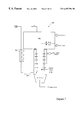
- FIG. 1 is a generalized, diagrammatic depiction of a land-based desalination installation
- FIG. 2 is a diagrammatic, side elevation view of an embodiment of a desalination fractionation column which utilizes positively buoyant hydrate and which may be employed in the installation shown in FIG. 1;
- FIGS. 3 and 4 are diagrammatic, side elevation views showing two alternative heat extraction portions of a desalination fractionation column employed in the installation shown in FIG. 1;
- FIG. 5 is a diagrammatic, side elevation view of another embodiment of a desalination fractionation column which utilizes positively buoyant hydrate and which may be employed in the installation shown in FIG. 1;
- FIG. 6 is a diagrammatic, side elevation view showing overlapping water vents used in the desalination fractionation column shown in FIG. 5;
- FIG. 7 is a diagrammatic, side elevation view of yet another embodiment of a buoyant hydrate-based desalination fractionation column employed in the installation shown in FIG. 1, which embodiment is similar to that shown in FIG. 5 .
- FIG. 8 is a diagrammatic, side elevation view of an embodiment of a desalination fractionation column which permits the utilization of negatively buoyant hydrate and which may be employed in the installation shown in FIG. 1;
- FIGS. 9 and 10 are schematic, isometric and end views, respectively, of the dissociation and heat exchange portion of the desalination fractionation column shown in FIG. 8;
- FIG. 11 is a Pressure/Temperature diagram depicting regions of CO 2 hydrate stability, the CO 2 liquidus, and the operating envelope for a negatively buoyant, CO 2 hydrate-based desalination system;
- FIG. 12 is a diagrammatic, side elevation view of a residual fluid replacement section designed to facilitate washing of the hydrate slurry;
- FIG. 13 is a diagrammatic, side elevation view of another embodiment of a desalination fractionation column which permits the utilization of a negatively buoyant hydrate, which embodiment facilitates separation of residual seawater from the negatively buoyant hydrate;
- FIG. 14 is a diagrammatic, side elevation view of a slurry holding, fluid separation apparatus used in the installation of FIG. 13;
- FIG. 15 is a diagrammatic, side elevation view of an embodiment of a desalination fractionation column configured to maintain the hydrate-forming gas at elevated pressure;
- FIG. 16 is a diagrammatic, side elevation view of an embodiment of a mechanically pressurized desalination system configured to use positively buoyant hydrate;
- FIG. 17 is a diagrammatic, side elevation view of an embodiment of a mechanically pressurized desalination system which is similar to that shown in FIG. 16 but which is configured to use negatively buoyant hydrate;
- FIG. 18 is a diagrammatic, side elevation view of an embodiment of a mechanically pressurized desalination system configured to use either positively or negatively buoyant hydrate;
- FIG. 19 is a generalized, diagrammatic depiction of a mechanically pressurized desalination system located on a ship.
- FIG. 1 A land-based desalination installation is shown schematically in FIG. 1 in generalized fashion.
- the installation may be divided roughly into three sections or regions: an intake portion 10 ; a water purification portion 12 ; and post-processing and downstream usage section 14 .
- the intake portion 10 consists essentially of the apparatus and various subinstallations necessary to extract seawater from the ocean 16 and transport it to the desalination/purification installation at region 12 , including subaquatic water intake piping 18 and pumping means (not shown) to draw the water from the ocean and pump it to shore for subsequent processing.
- Large volume installations can be located relatively close to the sea to reduce the piping distance of the input water to a minimum, and establishing the installation as close to sea level as possible will reduce the cost of pumping against pressure head.
- the intake pipeline 18 preferably extends sufficiently out to sea that it draws deep water, e.g., from the slope 20 of the continental shelf because deep water is more pure and colder than shallow water.
- water may be drawn from locations closer to land, e.g., from areas on the continental shelf 22 where the distance across the shallow water is too great for practice.
- the precise depth from which water is drawn will ultimately be determined by a number of factors, including primarily the specific embodiment of the desalination fractionation column which is employed, as described below.
- the desalination installation, per se is located so that the highest part of the fluid-handling system is at or below sea-level to reduce the costs of intake pumping.
- Pretreatment consists mainly of de-aeration, filtering to remove particulate matter and degassing, consistent with the requirement that material necessary for hydrate nucleation and growth not be removed from the water.
- FIGS. 2, 3 , and 4 A preferred embodiment of the purification installation 30 , per se, is illustrated in FIGS. 2, 3 , and 4 , which embodiment utilizes positively buoyant hydrate to extract fresh water from seawater.
- Seawater is pumped into the installation 130 at water input 32 and is pumped down to the lower, hydrate formation section 34 of the installation.
- the bottom of the hydrate formation section is no more than about 800 meters deep, and perhaps even shallower (again depending on the particular gas or gas mixture being used).
- a suitable, positively buoyant hydrate-forming gas (or liquid) is injected into the hydrate formation section at 36 , and positively buoyant hydrate 38 spontaneously forms and begins to rise through the water column, as is known in the art.
- the hydrate-forming gas can be pumped using sequential, in-line, intermediate pressure pumps, with the gas conduit extending either down through the fractionation column, per se, or down through the input water line so that gas line pressure is counteracted by ambient water pressure.
- gas conduit extending either down through the fractionation column, per se, or down through the input water line so that gas line pressure is counteracted by ambient water pressure.
- Hydrate formation is an exothermic process. Accordingly, as the positively buoyant hydrate forms and rises automatically through the water column—forming a hydrate “slurry” as hydrate crystals continue to nucleate and grow as they rise, until the hydrate-forming gas is used up—the surrounding water, which will increasingly become a concentrated saline “residue,” will be heated by the heat energy released during crystallization of the hydrate.
- the heated residual seawater will have a relatively decreased density and will rise in the column along with the hydrate 38 .
- the highly saline residual seawater will sink to the bottom of the water column. This highly saline residual seawater is collected in sump 40 at the bottom of the fractionation column and is removed.
- heated residual seawater is removed from the system in heat extraction portion 44 of the fractionation column at one or more points 46 .
- the heat extraction section 44 is shown in greater detail in FIG. 3 .
- water is pumped from the system as part of the vertical fractionation process. This is accomplished through a two-stage process.
- An internal sleeve 45 allows a primary separation to take place, as a water trap 49 is formed below the top of the sleeve. Hydrate continues to rise, while water floods the entire section 44 .
- Water is pumped from below the level at which hydrate exits from the top of the sleeve through fine conical screens 47 . These are designed to obstruct the passage of particulate hydrate. (The screens can be heated periodically to clear them of hydrate when flow restriction exceeds design limits.) Residual water is drawn off at a slow enough rate that any hydrate that may reside within water drawn toward the screen has a greater tendency to rise buoyantly than the tendency toward downwards or sideways movement associated with the force of suction of the drawn-off water. Very buoyant gas rises and stays within the column.
- FIG. 4 An alternative configuration 44 ′ of the heat extraction zone is shown in FIG. 4 .
- a centrifuge is used to allow a separate, mechanically-driven density fractionation system to operate.
- a segment 51 of the column is made mobile and capable of rotary movement.
- the mobile, rotary centrifuge column segment is carried by bearings 53 at the base 55 and at intervals along its height to keep it in vertical alignment with the entirety of the column, and to allow it to rotate with respect to the portions 57 , 59 of the column above and below it.
- This section is motor-driven, using a hydraulic system 61 driven from the surface.
- Vanes 63 within the centrifuge section will cause the water column to rotate, which vanes are designed based on turbine vane design to cause the hydrate-residual water in the section to rotate without turbulence and with increasing velocity toward the top of the section where residual water is extracted.
- Gravity “settling” or fractionation works here in a horizontal plane, where the heavier residual water “settles” toward the sides of the column while the lighter, more buoyant hydrate “settles” toward the center of the column. The hydrate continues to rise buoyantly and concentrates in the center of the centrifuge section. It will be appreciated that more than one such centrifuge section may be employed.
- the hydrate As the hydrate rises into the upper, dissociation and heat exchange region 50 of the desalination fractionation column, the depth-related pressures which forced or drove formation of the hydrate dissipate; accordingly, the hydrate, which is substantially in the form of a slurry, will be driven to dissociate back into the hydrate-forming gas (or mixture of gases) and fresh water.
- the hydrate-forming gas or mixture of gases
- heat energy in the surrounding seawater which ordinarily (i.e., in the prior art) would be absorbed by the hydrate as it dissociates is no longer available to the hydrate. Therefore, because heat has been removed from the system by extracting warmed residual seawater in the heat extraction portion 44 of the apparatus, a net or overall cooling bias is created in the upper, dissociation and heat exchange portion 50 of the installation.
- water being pumped into the system is passed in heat exchanging relationship through the regions of dissociating hydrate.
- the dissociation and heat exchange portion 50 may be constructed as one or more large, individual enclosures on the order of one hundred meters across. The input water will pass via a series of conduits through the regions of dissociating hydrate and will be cooled significantly as it does so.
- the input water is stabilized at 4° C. or below. This is because below that temperature, the density of the water increases, which enhances separation of the hydrate-water slurry formed by injections of the gas. Additionally, at a given pressure, hydrate nucleation proceeds faster at colder water temperatures.
- the system is run in a mode of maximum warm fluid extraction (to create a state of induced thermal bias) before equilibrium or steady-state is reached; although the duration of this start-up period will vary depending on the particular installation parameters, the design goal is that once steady-state is reached, the system can be run for extremely long operating periods without being shut down, i.e., periods on the order of years. Controlling residue water extraction, and thus heat removal, maintains a steady-state condition so that the apparatus does not keep cooling to below steady-state operating conditions.
- the fresh water is pumped off, e.a. as at 54 , and the gas is captured and recycled. (Provisions may be made for liquifying certain gases where this is desired.) Additionally, a portion of the water in the it dissociation and heat exchange region 50 will be “gray water,” which is fresh water containing some small portion of salts that have been removed from the hydrate by washing of the hydrate with water. The distinction between the “gray” or mixed water and pure fresh water is indicated schematically by dashed line 56 . The gray water may be suitable for drinking, depending on the salt concentration, or for agricultural or industrial use without further processing.
- the cold, gray water may be recycled back into the fractionation column, either by pumping it back down to the hydrate formation section 34 , as indicated at 58 ; or it may be injected back into the concentrated hydrate slurry at a region of the fractionation column located above the heat extraction portion 44 , as indicated at 60 , to increase the fluid nature of the hydrate slurry and to aid in controlling overall thermal balance of the system. Furthermore, providing gray water at 62 to dilute residual interstitial fluid allows for pre-dissociation washing.
- the fresh water preferably is treated by secondary treatment means 64 .
- the secondary treatment means may include, for example, fine filtering, gas extraction, aeration, and other processing required to bring the water to drinking water standard.
- the fresh water produced will be significantly cooled.
- This cooled water can be used to absorb heat from other applications or locations such as the insides of buildings, and hence can be used to provide refrigeration or provide for air-conditioning.
- the residual, concentrated seawater (which may be highly saline in nature) is simply pumped back to sea. Alternatively, it may be retained for those who desire it.
- the desalination fractionation column 130 will be on the order of 15 to 20 meters in diameter, or even larger.
- Conventional excavation and shaft-lining methodologies common to the mining and tunneling industry can be used in the construction of the column 130 .
- Overall dimensions will be determined based on the total desired fresh water production desired and relevant thermodynamic considerations. For example, one cubic meter of methane hydrate has the capacity to warm about 90 to 100 cubic meters of water by about 1° C. as it forms, and that same cubic meter of hydrate has the capacity to cool about 90 to 100 cubic meters of water by about 1° C. as it dissociates. (Mixes of suitable gases have higher heats of fusion, which makes the process more efficient.) Required cooling therefore will, in part, determine hydrate production rates, and hence dimensions of the system and the choice of gas or gases to meet those production rates.
- the diameter of the residual fluid removal column segment is larger. This facilitates buoyant, upward movement of the hydrate through the water column while first allowing separation of residue water from the hydrate in the heat extraction region 44 , and then dissociation and heat exchange in the dissociation and heat exchange region 50 .
- the dissociation and heat exchange region 50 may be constituted not just by a single dissociation “pool,” as shown schematically in FIG. 2, but rather may consist of a number of linked, heat-exchanging devices in a number of different water treatment ponds or pools.
- the actual depth, size, throughput, etc. will depend on the production rate, which will depend, in turn, on the temperature of the input water, the particular gas or gas mixture used to form the hydrate, the rate at which heat can be removed from the system, etc.
- the input of water into the base of the fractionation column can be controlled by a device (not shown) that alters the input throat diameter so as to facilitate mixing of the gas and water, thereby promoting more rapid and complete hydrate formation.
- hydrate formation can be enhanced by creating flow turbulence in the input water, just below or within the base of the hydrate forming gas injection port 36 . It may further be desirable to vary the diameter of the desalination fraction column in a manner to slow the buoyant descent of the hydrate slurry, thereby enhancing hydrate formation.
- the dissociation and heat exchange region 50 will be significantly wider and larger than the lower portions of the desalination column. This is because hydrate will be floating up into it and dissociating into gas and fresh water at a rate that is faster than that which could be accommodated in a pool that is the diameter of the column itself. Moreover, the requirement for heat will be great; if sufficient heat cannot be provided, water ice will form and disrupt the desalination process. Provision for physical constriction within a column will hold hydrate below the level where it dissociates freely, thus providing for a control on the amount of gas arriving at the surface. This is done for both normal operational and safety reasons.
- the heat exchanger apparatus may extend downward to the top of the residual water removal section.
- the dissociation and heat exchange pools do not need to be centered over the water column; moreover, more than one desalination fractionation column may feed upward into a given dissociation and heat exchange pool.
- groups of desalination fraction columns can be located close together so as to be supported by common primary and secondary water treatment facilities, thereby decreasing installation costs and increasing economy.
- FIG. 5 An alternate, slightly simplified embodiment 230 of a desalination fractionation column according to the invention is shown in FIG. 5 .
- hydrate formation occurs essentially within a thermal equilibration column 132 .
- the thermal equilibration column 132 has an open lower end 134 and is suspended in shaft 136 .
- input water is injected near the base of the desalination column 132 , e.g. as at 138 , preferably after passing through heat exchange and dissociation region 150 of the column 230 in similar fashion to the embodiment shown in FIG. 2 .
- Positively buoyant hydrate-forming gas is injected into the lower portions of the thermal equilibration column 132 , as at 140 , and hydrate will form and rise within the column 132 much as in the previous embodiment.
- the embodiment 230 is simplified in that heat of formation of the hydrate is transferred to water surrounding the thermal equilibration column 132 within a “water jacket” defined between the walls of the column 132 and the shaft 136 in which the desalination fractionation column is constructed.
- the hydrate formation conduit preferably is made from fabricated (i.e., “sewn”) artificial fiber material, which is ideal because of its light weight and its potential for being used in an open weave that greatly facilitates thermal equilibration between residual saline water within the thermal equilibration column 132 and seawater circulating within the water jacket.
- warmed water is pumped out of the system, this warmed water being water which has circulated within the water jacket.
- the intent of removing warmed water from the water jacket is not to remove so much heat energy that the input water is automatically cooled to temperatures suitable for formation of the hydrate at the base of the column, but rather it is simply to remove enough heat energy to prevent water within the interior of the hydrate formation conduit from becoming so warm that hydrate cannot form at all.
- the rate at which warm water is removed from the water jacket may be relatively small compared to the rate at which warm water is removed from the heat extraction portion 44 of the embodiment shown in FIG. 2 .
- the equilibration column 132 preferably is constructed with overlapping joints, as shown in FIG. 6 . This configuration permits the buoyant hydrate to rise throughout the column, while cooled, more saline water can flow out through the vents 142 , as indicated schematically.
- the desalination fractionation column installation may be further simplified by feeding the input water into the system without passing it through the dissociation section 250 of the embodiment 330 shown in FIG. 7 . If the input water is not sufficiently cold, more artificial refrigeration will need to be provided by refrigeration means 252 , but operation is otherwise the same as embodiment 230 shown in FIG. 5 .
- FIGS. 8-10 An embodiment 430 of a desalination fractionation “column” configured to permit the use of negatively buoyant hydrate for water purification is shown in FIGS. 8-10.
- the major difference between this embodiment 430 and the preceding embodiments of desalination fractionation columns is that the heat exchange and dissociation portion 350 of the installation is laterally or horizontally displaced or offset relative to the hydrate formation and heat removal sections 336 and 346 , respectively.
- the hydrate formation and heat removal sections are similar to those in the embodiments described above.
- a number of different operating gases can be employed with this configuration.
- Low molecular weight gases such as O 2 , N 2 , H 2 S, Ar, Kr, Xe, CH 4 , and CO 2 all form hydrates under different pressure-temperature conditions.
- Each of the different hydrate-forming gas systems will require special design of the hydrate column which is tailored to the particular gas used in the installation, but the principles of hydrate formation to extract fresh water will remain the same.
- adding small amounts of additive gas(es) to the primary hydrate-forming gas may broaden the hydrate stability field in the same way the methane hydrate stability field is expanded by mixing higher density hydrocarbon gases with methane.
- Carbon dioxide (or carbon dioxide-based gas mixtures, referred to herein simply as “carbon dioxide” for simplicity) is an ideal gas to use for a number of reasons: carbon dioxide does not combust under the physical and thermal conditions encountered in the hydrate desalination apparatus, and is thus virtually hazard-free; carbon dioxide hydrate is stable at shallower depths than methane hydrate (and about the same as mixed gas methane hydrate); even if present dissolved in relatively high concentrations, carbon dioxide is safe for human consumption—in fact, fresh water produced using carbon dioxide can be made so as to retain some quantity of the carbon dioxide, thereby providing soda water that is similar to many popular brands but that is different in at least one significant way: it will contain all the naturally occurring minerals found in seawater in proportion to the remaining salts not removed during the desalination process—and is not offensive to either taste or smell (as would be the case of H 2 S hydrate); carbon dioxide hydrate is, like methane, tasteless and odorless; there is considerable recent experimental information which demonstrate clearly the actual marine behavior
- FIG. 11 shows, for example, the carbon dioxide hydrate stability regions superimposed over the carbon dioxide phase diagram.
- the shaded portion of the diagram indicates that carbon dioxide hydrate (formed from carbon dioxide gas) is stable at from an upper pressure limit of about 18 atmospheres, just above 0° C., to about 40 atmospheres pressure at just above about 8° C.
- the liquidus extends from about 37 atmospheres pressure at just above 0° C., to about 40 atmospheres pressure at just above 8° C.
- carbon dioxide exists as a gas; below the liquidus, carbon dioxide spontaneously compresses to a liquid.
- the system is constructed so that, assuming carbon dioxide is used as the operating gas, the carbon dioxide is injected into the hydrate formation portion of the column at ambient temperature and pressure that is within the operating region 450 that consists of the portion of the carbon dioxide hydrate stability zone that lies above the carbon dioxide liquidus and above the freezing point of water.
- the practical result of this is that the range of water depths at which carbon dioxide may be used as the operating gas is relatively small and is comparatively shallow. Accordingly, a relatively shallow land apparatus can be constructed, which will reduce construction complexity and cost.
- carbon dioxide (or other negatively buoyant hydrate-forming gas, as desired) is injected near the base of the hydrate formation section 336 (e.g., at 352 ) and mixed with supply or input seawater that has been chilled by being passed through the heat exchange and dissociation portion 350 and/or by “artificial” refrigeration, as at 354 .
- the carbon dioxide hydrate will float only if the formation of the hydrate is incomplete such that a complex, hydrate-gas meshwork is formed. This condition is met when the gas is injected rapidly and in relatively large bubbles.
- the carbon dioxide hydrate isolates carbon dioxide gas bubbles from the surrounding seawater, thereby preventing further formation of hydrate.
- the combined gas/liquid carbon dioxide and hydrate is positively buoyant, even though the hydrate per se is negatively buoyant (ie., has a greater specific gravity than the seawater), and floats upward, as at 356 . Additionally, some of the bubbles will burst and new hydrate shells will be formed; hydrate shells with gas bubbles predominantly form new carbon dioxide hydrate rims, which are assisted upward by carbon dioxide gas which tends to adhere to solid hydrate particles.
- the system is designed to produce as much hydrate as possible, consistent with leaving enough warm, lower-density, residual fluid to form a “flux” and to allow extraction of heat by removing the residual seawater in the heat extraction section 346 .
- the system furthermore has the capacity for very rapid liquid or gas injection, which may be in time-sequence bursts rather than being continuous. It is intended that not all gas form hydrate, as noted above, to ensure incomplete formation of hydrate. Thus, larger quantities of gas are required for a negatively buoyant hydrate-based system than for a complete hydrate-forming gas system such as the positively buoyant hydrate-based systems described above.
- This carries the hydrate upward through the column until it reaches a lateral deflection zone 362 , where the hydrate/residual seawater slurry is diverted horizontally or laterally relative to the hydrate formation and heat removal sections 336 and 346 and into the dissociation and heat removal section 350 .
- the hydrate in large measure continue to move upward and over into the heat exchange and dissociation region of the column 350 due to this momentum.
- the hydrate loses momentum within the heat exchange and dissociation portion 350 it will settle and dissociate into the gas and fresh water, which will separate from residual seawater as described in greater detail below.
- the sunken hydrate and concentrated residual brine are pumped out of the sump at 365 and separated by appropriately configured separation means 366 .
- the waste saline water 368 is disposed of as appropriate, and a slurry consisting of the sunken hydrate is pumped upwardly as indicated at 370 and is discharged into the heat exchange and dissociation chamber 350 , e.g. at 372 , where the hydrate dissociates into gas and fresh water.
- the hydrate whether delivered or transported to the chamber via the lateral deflection portion 362 of the column or pumped from the sump of the desalination fractionation column 364 , will dissociate into fresh water and the hydrate-forming gas.
- the assisted buoyancy hydrate slurry rising through the desalination fractionation column enters the chamber as at 360 after being diverted laterally at deflection portion 362 , as indicated schematically in FIG. 9 .
- hydrate slurry being pumped from the sump is injected into the dissociation chamber at 372 , where it may be placed within special fluid separation devices.
- the dissociation and heat exchange chamber is constructed with a number of canted separator shelves 380 which extend from one end of the chamber to the other, as well as from one side of the chamber to the other. The canted nature of the shelves allows the denser saline water to sink and the lighter fresh water to rise within and between the shelves, thereby minimizing turbidity and mixing of saline and fresh water.
- the separator shelves 380 are canted in that they slope downward, both from one end of the chamber to the other as well as from one side of the chamber to the other.
- the separator shelves have pass-through apertures 382 which allow the denser, saline water to sink within the system and the less dense, fresh water to rise within the system to the top of the chamber as the hydrate dissociates into the fresh water and gas.
- Fresh water which is cooled due to the cooling bias created by the removal of warm residual water as described above in connection with the positively buoyant hydrate embodiments, is removed as at 384 and may be used for cooling as well as for potable water.
- “Gray” water and saline residue are removed from lower portions of the heat exchange and dissociation chamber 350 , as at 386 and 388 , and are handled as described above in the context of the positively buoyant hydrate embodiments, ea., gray water may be used for drinking or industrial applications and the saline residue may be recycled back as input into the base of the desalination fractionation column.
- liquid carbon dioxide can be used to form assisted buoyancy hydrate.
- liquid carbon dioxide is more buoyant than seawater (although not as buoyant as gaseous carbon dioxide.)
- a resultant meshwork of hydrate and liquid carbon dioxide is formed which is positively buoyant.
- the meshwork mass will rise spontaneously as a whole immediately upon forming and will behave essentially the same as a hydrate meshwork formed from gaseous carbon dioxide and carbon dioxide hydrate.
- liquid carbon dioxide at depths of five hundred meters or more—well below the liquidus—is possible without the need for deep, in-line pumps.
- deeper (i.e., higher pressure) injection of liquid carbon dioxide will promote very rapid crystallization and growth of the hydrate crystals.
- the fluid removal section 44 (FIG. 2) is constructed as an alternating sequence of fresh water injection subsections 412 and fluid removal subsections 414 constructed as shown in either FIG. 3 or FIG. 4 .
- the benefits of removing the interstitial saline fluid include additional heat removal; washing of the slurry (i.e., is removal of pollutants or adhering ions or particulate material from the surface of the hydrate crystals) by fluid replacement; and direct removal of saline interstitial water from the hydrate slurry and dilution or replacement of the original saline interstitial fluid produced by the process of hydrate formation.
- washing of interstitial water is strongly recommended for the slurry mixture of liquid carbon dioxide and carbon dioxide hydrate so as to minimize turbulence and mixing attributable to the liquid carbon dioxide converting to gaseous carbon dioxide
- washing the slurry and flushing saline interstitial fluid therefrom would also provide benefits for any positively buoyant hydrate-based or assisted buoyancy hydrate-based system.
- injecting cold water (either fresh or gray) from the dissociation section into the hydrate slurry will remove additional heat from the hydrate at the same time that saline interstitial water is flushed from the hydrate slurry.
- multiple residual water flushings will ensure greater fresh water production.
- FIGS. 13 and 14 Another embodiment 530 of a desalination fractionation “column” which is configured to utilize negatively buoyant hydrate and which facilitates separation of the hydrate and residual seawater is illustrated in FIGS. 13 and 14.
- the “column” is configured as an asymmetric, U-shaped installation, which consists primarily of a seawater input conduit 432 , a hydrate formation and catch sump region 434 , and a residue fluid riser conduit 436 .
- the seawater input conduit passes through a dissociation and heat exchange region 438 which, in this embodiment, is configured especially as a hydrate “catch basin”
- the input water is passed through the dissociation/heat exchange catch basin 438 in heat exchanging relationship with dissociating hydrate in order to chill the input seawater.
- the input seawater is pumped to the base 440 of the column, where it turns and flows upward and laterally through elbow portion 442 before entering the hydrate formation and catch sump 434 .
- Negatively buoyant hydrate-forming liquid or gas is injected into the input seawater in the hydrate formation and catch sump at 444 .
- Means 945 for liquifying certain gases are provided; residual fluid can be used in a heat exchanger 457 to provide cooling for the liquification process.
- Injection of the gas or liquid is controlled such that hydrate formation is complete (in contrast to incomplete, as in the case of the previously described, assisted buoyancy embodiment), i.e., such that all gas is utilized to form hydrate.
- the negatively buoyant hydrate settles to the bottom of the catch sump 434 . As the hydrate settles, it displaces the residual seawater, which is warmed by the heat liberated during hydrate formation. The residual seawater therefore rises buoyantly through residue fluid riser conduit 436 , and it is pumped out of the system to remove heat and create a cooling bias in the system as in the previously described embodiments.
- the rate of formation and settling of the hydrate is controlled such that it “packs” down to the point of being grain supported.
- Mechanical apparatus such as a vibration tray is located on the sloping floor 439 of the settling portion of the hydrate-residual fluid chamber 434 . This concentrates the hydrate and minimizes residual fluid remaining so that the hydrate can be pumped rapidly, as a slurry, from the base of the sump up into the dissociation/heat exchange catch basin 438 via slurry pumping conduit 446 .
- the hydrate slurry is pumped to the dissociation/heat exchange catch basin 438 at a rate that is generally faster than the rate at which positively buoyant hydrates rises in the previously described embodiments.
- a preferred slurry holder and fluid separator consists of a fixed, wide-mouthed, upwardly open tank or tanks 450 (FIG. 14) that receive the hydrate slurry from above.
- Each tank holds the negatively buoyant hydrate from the hydrate slurry transfer system 446 and prevents it from sinking to toward the base of the dissociation chamber 438 .
- the hydrate slurry is delivered by pipes 448 to a number of hydrate spreaders consisting of vanes or rotating vanes designed to disperse the granular hydrate 468 .
- the negatively buoyant hydrate separates while falling to a screen shelf 470 in the tank. This allows saline water to sink through the screen shelf at the base of the circulating input water intercooler system 474 , which transfers heat from the input water to the dissociating hydrate and feeds the cooled water downward to be treated.
- a number of residual water delivery pipes 475 extend downward from the base of this slurry holding tank, which allows heavier saline water to flow to the base of the vessel without disturbing the water surrounding these pipes.
- the main interface 477 dashed line
- the main interface 477 between fresh and saline water will be located somewhere the lower part of the dissociation/heat exchange chamber 438 , where saline water naturally collects below fresh due to density differences. Saline water is removed at the base of the chamber 480 , and provision is also made for gray water removal as at 482 .
- slurry holding tanks may be placed within a given dissociation/heat exchange chamber so that the flow of hydrate slurry can be rapid enough to prevent clogging or freezing up of any one tank. Circulating input water may be passed first through one slurry holding tank and then through another to minimize temperature of the input water as it exits the dissociation/heat exchange chamber.
- All fluids will find their relative positions according to natural buoyancy or through a process of fractionation. All internal piping in the vessel can be fabricated from inexpensive plastic or other material. This method of fluid separation may also be installed in the dissociation/heat exchange section of the assisted buoyancy and pumped sump embodiment shown in FIG. 8 .
- the slurry pumping conduit 446 is constructed as a variable volume pipe, in order to permit periodic pumping of hydrate without allowing the hydrate to settle or move upward slowly.
- a variable volume pipe can be fabricated relatively easily by inserting a flexible sleeve within the slurry pumping conduit 446 around which fluid can flood when the pressure within the liner is reduced.
- the injection point 444 of the hydrate-forming liquid or gas is positioned above the base of the column 440 so that in the event of incomplete hydrate formation (which would result in the formation of assisted buoyancy hydrate), any excess gas which does not form hydrate (along with assisted buoyancy hydrate) will rise up the residue fluid riser conduit 436 . (Very little hydrate will escape with gas up the residue fluid riser conduit 436 , and any such hydrate will have dissociated prior to arriving at the top of the residue riser section.
- flow rate controls such as constrictors should be used to keep the rate of flow of fluid through the system low enough to keep solid hydrate from being swept up the residue fluid riser conduit 436 .
- the design of the hydrate formation and catch sump 434 , as well as the lower portion of the residue fluid riser conduit, should be designed to facilitate “clean” separation of the hydrate from the residue fluid. Accordingly, the hydrate formation and catch sump 434 is designed to impart lateral movement to the residue fluid as well as to permit upward movement thereof.
- the weight of the column of water creates the pressures required for hydrate formation.
- the minimum pressure depth at which hydrate is stable is far greater than at sea level, where the pressure is one atmosphere. Accordingly, the hydrate begins to dissociate at relatively elevated pressures.
- Various ones of the embodiments described above may be modified so as to collect the fresh water released from the hydrate and to capture the released gas at the region of the fractionation column where the dissociation takes place, rather than at the top of the column (surface level; one atmosphere ambient pressure), with certain resultant advantages.
- relatively large volumes of hydrate-forming gases and gas mixtures are required to desalinate large volumes of water. Therefore, if the gas is captured, processed for re-injection, and stored while maintained at elevated pressures (e.g., the pressure at which the hydrate begins to dissociate), the volume of gas that must be handled will be much smaller than would be the case if the gas were allowed to expand fully as it rises to the surface and pressure drops to atmospheric.
- the hydrate-forming gas is kept pressurized, raising its pressure to the pressure required for injection in the hydrate-forming section requires far less recompression of the gas and hence is less costly.
- FIG. 15 A preferred embodiment 600 in which dissociation and gas capture and processing are controlled so as to be kept at elevated pressure is illustrated in FIG. 15 .
- a physical barrier 610 extends across the fractionation column and blocks the upward movement of the hydrate slurry.
- the location of the barrier 610 depends on the stability limits of the particular hydrate-forming substance used, but will be above the region of hydrate stability (i.e., at lesser pressure-depth).
- the released gas forms a pocket at trap 620 and enters a gas recovery and processing system 626 while still at a pressure depth considerably greater than one atmosphere surface pressure.
- the gas processing system 626 may contain means for liquifying certain gases.
- the gas is processed and re-injected into the hydrate formation section 628 at 629 in the same manner as in the previously described embodiments, except the gas system is maintained at considerably higher pressure.
- the hydrate dissociation section 630 extends downward to some particular depth determined by the particular hydrate-forming gas being used. Because the hydrate dissociates under “controlled,” elevated pressure, the dissociation reaction will proceed generally more slowly than in the above-described embodiments. Therefore, the heat exchanger 632 present in the dissociation/heat exchanger section (as described in connection with previous embodiments) is designed to accommodate the particular, slower reaction rates. Input water 634 is passed through the dissociation/heat exchange section in heat exchanger 632 and is injected into the base of the desalination fractionation column at 636 , as in previously described embodiments.
- One or more fresh water bypass pipes 640 communicate with the dissociation region at a point 641 located above the fresh water/saline water interface 644 but below the upper boundary 648 of the hydrate stability field.
- the pipe(s) 640 which are screened or otherwise configured to prevent hydrate from entering them, deliver fresh water released from the hydrate to fresh water accumulation region 666 .
- a gray water return pipe 650 allows denser, more saline gray water to flow back down into the saline fluid below the fresh water/saline water interface 644 . More highly saline residual water and/or negatively buoyant hydrate is drawn from the sump 654 and processed or removed as at 658 , as in previously described embodiments.
- Output fresh water is drawn off at 660 , near the top of the fresh water accumulation region 666 and well above the physical barrier 610 .
- the physical barrier 610 , the fresh water and gray water return pipes 640 , 650 , and the heat exchanger in the dissociation/heat exchange section 630 may be configured such that their positions can be varied, thereby permitting different hydrate-forming liquids, gases, or gas mixtures to be used in the same installation.
- the physical barrier 610 and heat exchanger might be vertically adjustable, whereas a series of bypass and return pipes 640 , 650 having different inlet locations can be provided and opened and closed remotely using suitable inlet and outlet valves. In this manner, changing from one hydrate-forming substance to another can be effected very quickly and conveniently.
- the upper part of the desalination fractionation column can be sealed and pressurized by means of an associated hydraulic standpipe, thereby causing pressures within the apparatus near the surface to be equivalent to the pressure-height of the standpipe.
- the standpipe is implemented in tall structures (such as adjacent buildings near the desalination facility)
- relatively high pressures can be created in the topmost part of the dissociation/heat exchange section, which is at ground level.
- the water may be desalinated or purified in self-contained, mechanically pressurized vessels.
- Such embodiments offer a number of distinct advantages, including the fact that the installations can be of various sizes and shapes to suit local conditions, containment constraints, and fresh water requirements.
- the previously described embodiments are relatively large-scale and therefore are of a fixed, permanent nature, self-contained, pressurized embodiments can be more temporary in nature in terms of their construction and their location.
- Individual pressurized installations can occupy relatively small spaces and produce fresh water efficiently, even in low volumes.
- Such installations can be fabricated at central manufacturing facilities and installed on site with a minimum of local site construction, which site might be a building or even a ship or other mobile platform.
- FIG. 16 A mechanically pressurized installation configured to use positively buoyant hydrate to extract fresh water from water is illustrated in FIG. 16 .
- Input water is pumped and pressurized from input pressure to the operating system pressure by pump 704 .
- the water enters the pressurized hydrate formation and separation vessel 710 at water input 711 , and a suitable, positively buoyant hydrate-forming substance is injected at injection point 712 .
- a suitable, positively buoyant hydrate-forming substance is injected at injection point 712 .
- Positively buoyant hydrate 714 spontaneously forms and rises through the residual water, as in previously described embodiments, to the top of the vessel 710 where it accumulates and concentrates.
- the buoyant hydrate slurry is subsequently admitted into transfer and washing section 720 , and then into the dissociation/heat exchange vessel 722 .
- Flow of the hydrate slurry is regulated by valves 734 .
- the hydrate While in the transfer and washing section 720 , the hydrate may be washed of the residual, intergranular saline fluid using fresh water 726 tapped from the fresh water output 728 . More than one wash cycle may be used to completely flush residual fluid, although the number of washings will depend on the effectiveness of separation through fractionation (which may vary for different gases and gas mixtures) and the nature of the crystalline fraction of the slurry. In some cases, no washing may be necessary.
- Pressure is maintained in the hydrate formation and separation vessel 710 and in the dissociation/heat exchange vessel 722 by pressure balance reservoir systems 732 (one for each vessel), and movement of fluid from one vessel to the other is controlled by varying pressure and using the in-line valves 734 .
- the systems 732 each have a pressure pump 733 and a diaphragm or gas-fluid interface 736 , which are used to raise and lower pressure in each vessel.
- Pressure in the vessels is controlled so that the hydrate remains stable as hydrate until it is finally collected and concentrated at the top of the dissociation vessel 722 . This is because premature dissociation will release considerable amounts of gas and therefore will cause undesired mixing.
- pressure conditions in the dissociation vessel should be controlled to minimize turbulence in the fluid-gas mixture and to promote efficient separation of saline and fresh water.
- the dissociation and heat exchange vessel 722 may be constituted by a number of linked, heat-exchanging devices in a number of different water treatment chambers.
- the actual size, throughput, etc. will depend on the overall system production rate which, in turn, will depend on the temperature of the input water, the particular liquid, gas, or gas mixture used to form the hydrate, the rate at which heat can be removed from the system, etc.
- Fractionation, concentration, separation, drying, and re-use of the hydrate-forming gas takes place in the same manner as in the previously described embodiments. Additionally, heat produced by liquifying hydrate-forming gas can be absorbed and removed using heat exchangers containing residue or saline fluids.
- the mechanically pressurized process is inherently less continuous than the previously described embodiments and is essentially a batch process.
- Pressure in the system is controlled so as to simulate the pressure variation in the previously described embodiments: the water to be treated is pressurized and injected into the apparatus, and then pressure is raised and lowered to control the rate of the hydrate formation and dissociation reactions.
- Mechanically pressurized embodiments provide increased versatility in that pressures may be controlled to provide the optimum pressures for formation of hydrate and to control the rate of dissociation.
- different liquids, gases, and gas mixtures can be used within the same apparatus, and the same water can be processed more than once using different liquids, gases, and gas mixtures.
- FIG. 17 A further mechanically pressurized embodiment 800 , which embodiment utilizes negatively buoyant hydrate to extract fresh water from water to be treated, is shown in FIG. 17 .
- Input water is pumped from input pressure up to the operating system pressure and into the pressurized hydrate formation and separation vessel 810 by pumps 804 , and a suitable, negatively buoyant hydrate-forming gas is injected at injection point 812 .
- a suitable, negatively buoyant hydrate-forming gas is injected at injection point 812 .
- Negatively buoyant hydrate 814 spontaneously forms and sinks through the residual water, as described in connection with previously described negatively buoyant hydrate embodiments, and collects and concentrates in gated sump isolation sections 816 , which are opened and closed to control passage of the hydrate therethrough.
- pressure is maintained in the system by pressure balance reservoir systems 832 (one for each vessel), and movement of the fluid can be controlled by varying the pressure in the system compartments.
- Pressure pumps 830 and diaphragms or gas-fluid interfaces 836 are used to raise and lower pressure in each vessel independently.
- the hydrate slurry may be washed of the residual, intergranular saline fluid with fresh water tapped from the fresh water output 828 , which removes salt from the hydrate slurry prior to dissociation.
- the hydrate is permitted to flow downward from the transfer and washing section 820 , and into the hydrate dissociation and heat exchange vessel 822 , where is dissociates and fresh, gray, and saline water are removed.
- Heat exchange between the input water and the dissociating hydrate slurry occurs as described in previous embodiments. Dissociation takes place under controlled pressure conditions to minimize turbulence in the fluid-gas mixture and to promote efficient separation of saline and fresh water.
- a slurry holder and fluid separator tank 860 is provided in the upper part of the dissociation/heat exchange vessel 822 and is similar in construction to that described above and shown in FIGS. 12 and 13.
- the tank 860 minimizes mixing of fresh and saline water by providing a conduit for the residual saline water to sink to the bottom of the vessel, which conduit isolates the saline water from the lower density fresh water.
- the dissociation and heat exchange vessel 822 may be constituted by a number of linked, heat-exchanging devices in a number of different water treatment chambers.
- the actual size, throughput, etc. will depend on the production rate which, in turn, will depend on the temperature of the input water, the particular liquid, gas, or gas mixture used to form the hydrate, the rate at which heat can be removed from the system, etc. Fractionation, concentration, separation, drying, and re-use of the hydrate-forming substance takes place in the same manner as in the previously described embodiments.
- FIG. 18 Another embodiment 900 , which embodiment provides greater versatility by using either positively or negatively buoyant hydrate to extract fresh water from seawater or polluted water, is shown in FIG. 18 .
- Pumps P and in-line valves 914 are provided throughout the system. Operation, depending on the particular hydrate-forming substance used, is as described in the pressurized vessel installations using either positively or negatively buoyant gas hydrate.
- This embodiment is particularly useful where the gas or gas mixture supply is uncertain as a variety of gases may be used. Embodiments of this type could be useful in disaster relief or in expeditionary military activity, or at any place where a temporary supply of fresh water is required without a significant construction requirement.
- This embodiment contains all the attributes of both the positive and negative buoyancy hydrate, mechanically pressurized-desalination fractionation embodiments, including use of fresh water 926 from the fresh water output 928 to flush residual saline water.
- Multiple liquid or gas injection points 908 are provided, as well as provision for handling either positively or negatively buoyant hydrate.
- multiple pumping units P and fluid control valves 914 are provided to direct the flow of fluids and hydrate slurries in fluid control and washing units 916 and hydrate slurry control units 918 .
- the gas processing system 944 includes means for liquifying certain recovered gases and gas mixtures.
- any of the mechanically pressurized vessel installations may be simplified by feeding the input water into the system without passing it through the dissociation section for heat exchange. More artificial refrigeration will need to be provided, but operation will otherwise be the same as for the positive and negative buoyancy hydrate embodiments shown in FIGS. 16 and 17 and the “combined” pressurized apparatus as shown in FIG. 18 .
- mechanically pressurized embodiments of the invention may be extremely mobile.
- water to be treated is processed as described in previous embodiments, but in a smaller and more compact installation built right on board the ship 1000 .
- Negatively buoyant hydrate formed from a liquid or gas (such as carbon dioxide) that is non-combustible at the pressures and temperatures-of this system and the surrounding ambient conditions is preferred, especially where installations are placed in ships or where the handling of combustible gases constitutes a hazard.
- the heat produced by the hydrate formation reaction is extracted by heat exchangers in the hydrate formation and concentration vessel, which is possible because of the immediate access to seawater. Further heat is extracted from the hydrate slurry in the hydrate slurry transfer system. This pre-dissociation heat extraction maximizes the cooling effect of the hydrate dissociation because removing heat in addition to that removed with the residual treated fluid allows dissociation to begin with the hydrate slurry at a lower temperature than would exist otherwise.
- the fresh water produced will be significantly cooled.
- This cooled water can be used to absorb heat and hence can be used to provide refrigeration or air-conditioning.
- the fresh water is treated as described in previous embodiments, and warmed residual water may be used as a low-grade heat source (although it is more likely to be pumped back to the sea).
- Installation aboard a ship is ideal for the mechanically pressurized hydrate fractionation method of desalination. This is because the residual treated water can be returned to the sea immediately, thereby maximizing efficiency of the heat-removal process.
- the water intake for the desalination ideally would be placed as low on the keel 1010 of the ship as possible to separate intake and residual water return and to minimize uptake of pollutants, which in the case of oil-based products and many industrial chemicals either float or are usually found in increasing proportion closer to the sea surface.
- the return fluid can have multiple outlets 1020 , which allows it to be returned to the sea closer to the surface where the warmer water will float well away from the water intake.
- movement of the ship creates considerable turbulence which will promote mixing of the residual water and near-surface water when the ship is under way.
- water from a shore source can be used or the system can be recycled with fresh water to minimize residual water return, and the desalination fractionation system can be operated at a minimal level, i.e., at a level just sufficient for the thermal balance required for normal operation to be attained quickly.
- the residual water can be returned to the sea directly. Wind and tide can be taken into consideration to select the return outlet utilized so as to minimize environmental impact and allow the residual water to be carried away from the ship most efficiently.
- Similar compact installations can be fabricated as pre-packaged components that can be airlifted or easily flown and trucked to a particular site—for instance, immediately following a disaster such as an earthquake—and assembled rapidly.
- temporary or mobile installations are operated, more compact versions of the intake, outfall, and gas processing apparatus similar to that described for FIG. 1 are employed. These can be specially designed for light weight, ease of deployability, and ability to operate in a variety of conditions.
- Power generating units or power cables suitable for drawing electricity from any inshore powerboat or other supply are also part of the mobile apparatus, and possibly also part of larger temporary facilities.
- Pressurized vessel desalination fractionation installations can also be mounted on standard pallets for shipment in aircraft or ships or in standard commercial shipping containers (for which cargo handling equipment exists world-wide) to facilitate air and road travel. They can be mounted on vehicles or set up on a pier, or anywhere near seawater or other water to be desalinated or purified.
Abstract
Description
Claims (5)
Priority Applications (17)
| Application Number | Priority Date | Filing Date | Title |
|---|---|---|---|
| US09/397,500 US6497794B1 (en) | 1999-07-12 | 1999-09-17 | Desalination using positively buoyant or negatively buoyant/assisted buoyancy hydrate |
| US09/500,422 US6475460B1 (en) | 1999-07-12 | 2000-02-09 | Desalination and concomitant carbon dioxide capture yielding liquid carbon dioxide |
| EP03004899A EP1350766A1 (en) | 1999-07-12 | 2000-05-18 | Desalination using positively buoyant or negatively buoyant/assisted buoyancy hydrate and concomitant carbon dioxide capture yielding liquid carbon dioxide |
| AU48542/00A AU767017B2 (en) | 1999-07-12 | 2000-05-18 | Desalination using positively buoyant or negatively buoyant/assisted buoyancy hydrate and concomitant carbon dioxide capture yielding liquid carbon dioxide |
| CN00811656A CN1382107A (en) | 1999-07-12 | 2000-05-18 | Desalination using positively buoyant or negatively buoyant/assisted buoyancy hydrate and concomitant carbon dioxide capture yielding liquid carbon dioxide |
| PCT/US2000/013506 WO2001004056A1 (en) | 1999-07-12 | 2000-05-18 | Desalination using positively buoyant or negatively buoyant/assisted buoyancy hydrate and concomitant carbon dioxide capture yielding liquid carbon dioxide |
| EP00930782A EP1200355A1 (en) | 1999-07-12 | 2000-05-18 | Desalination using positively buoyant or negatively buoyant/assisted buoyancy hydrate and concomitant carbon dioxide capture yielding liquid carbon dioxide |
| MXPA02000416A MXPA02000416A (en) | 1999-07-12 | 2000-05-18 | Desalination using positively buoyant or negatively buoyant/assisted buoyancy hydrate and concomitant carbon dioxide capture yielding liquid carbon dioxide. |
| IL14755200A IL147552A (en) | 1999-07-12 | 2000-05-18 | Desalination using positively buoyant or negatively buoyant/assisted buoyancy hydrate and concomitant carbon dioxide capture yielding liquid carbon dioxide |
| PE2000000690A PE20010603A1 (en) | 1999-07-12 | 2000-07-11 | INSTALLATION AND METHOD TO DESALINATE SALT WATER OR PURIFY CONTAMINATED WATER |
| ARP000103566A AR024716A1 (en) | 1999-07-12 | 2000-07-12 | DESALINIZATION THAT USES POSITIVELY FLOATING OR NEGATIVALLY FLOATING / FLOATING HYDRAULES ASSISTED AND COMFORTABLE FLOATING CARBON ANHYDRIDE PRODUCTION LIQUID CARBON ANHYDRIDE PRODUCTION |
| US09/941,545 US6767471B2 (en) | 1999-07-12 | 2001-08-30 | Hydrate desalination or water purification |
| US10/266,258 US6733667B2 (en) | 1999-07-12 | 2002-10-08 | Desalination using positively buoyant or negatively buoyant/assisted buoyancy hydrate |
| ARP020104323A AR037302A2 (en) | 1999-07-12 | 2002-11-11 | A METHOD TO CAPTURE CARBON ANHYDRIDE AND PRODUCE PURIFIED WATER; AND AN INSTALLATION TO TREAT EXHAUST GAS AND SALT WATER OR CONTAMINATED IN GENERAL SIMULTANEOUSLY |
| US10/656,339 US6969467B1 (en) | 1999-07-12 | 2003-09-08 | Hydrate-based desalination with hydrate-elevating density-driven circulation |
| US10/833,175 US20040195160A1 (en) | 1999-07-12 | 2004-04-28 | Hydrate-based reduction of fluid inventories and concentration of aqueous and other water-containing products |
| US11/504,659 US7255794B2 (en) | 1999-07-12 | 2006-08-16 | Hydrate-based reduction of fluid inventories and concentration of aqueous and other water-containing products |
Applications Claiming Priority (3)
| Application Number | Priority Date | Filing Date | Title |
|---|---|---|---|
| US09/350,906 US6565715B1 (en) | 1999-07-12 | 1999-07-12 | Land-based desalination using buoyant hydrate |
| US09/375,410 US6531034B1 (en) | 1999-07-12 | 1999-08-17 | Land-based desalination using positively buoyant or negatively buoyant/assisted buoyancy hydrate |
| US09/397,500 US6497794B1 (en) | 1999-07-12 | 1999-09-17 | Desalination using positively buoyant or negatively buoyant/assisted buoyancy hydrate |
Related Parent Applications (1)
| Application Number | Title | Priority Date | Filing Date |
|---|---|---|---|
| US09/375,410 Continuation-In-Part US6531034B1 (en) | 1999-07-12 | 1999-08-17 | Land-based desalination using positively buoyant or negatively buoyant/assisted buoyancy hydrate |
Related Child Applications (4)
| Application Number | Title | Priority Date | Filing Date |
|---|---|---|---|
| US09/500,422 Continuation-In-Part US6475460B1 (en) | 1999-07-12 | 2000-02-09 | Desalination and concomitant carbon dioxide capture yielding liquid carbon dioxide |
| US09/941,545 Continuation-In-Part US6767471B2 (en) | 1999-07-12 | 2001-08-30 | Hydrate desalination or water purification |
| US09491545 Division | 2001-08-30 | ||
| US10/266,258 Division US6733667B2 (en) | 1999-07-12 | 2002-10-08 | Desalination using positively buoyant or negatively buoyant/assisted buoyancy hydrate |
Publications (1)
| Publication Number | Publication Date |
|---|---|
| US6497794B1 true US6497794B1 (en) | 2002-12-24 |
Family
ID=46276490
Family Applications (2)
| Application Number | Title | Priority Date | Filing Date |
|---|---|---|---|
| US09/397,500 Expired - Fee Related US6497794B1 (en) | 1999-07-12 | 1999-09-17 | Desalination using positively buoyant or negatively buoyant/assisted buoyancy hydrate |
| US10/266,258 Expired - Fee Related US6733667B2 (en) | 1999-07-12 | 2002-10-08 | Desalination using positively buoyant or negatively buoyant/assisted buoyancy hydrate |
Family Applications After (1)
| Application Number | Title | Priority Date | Filing Date |
|---|---|---|---|
| US10/266,258 Expired - Fee Related US6733667B2 (en) | 1999-07-12 | 2002-10-08 | Desalination using positively buoyant or negatively buoyant/assisted buoyancy hydrate |
Country Status (1)
| Country | Link |
|---|---|
| US (2) | US6497794B1 (en) |
Cited By (9)
| Publication number | Priority date | Publication date | Assignee | Title |
|---|---|---|---|---|
| US6562234B2 (en) * | 1999-07-12 | 2003-05-13 | Marine Desalination Systems L.L.C. | Land-based desalination using positively buoyant or negatively buoyant/assisted buoyancy hydrate |
| US20040058537A1 (en) * | 2000-08-25 | 2004-03-25 | Canon Kabushiki Kaisha | Method and apparatus for separating sample |
| US6733667B2 (en) * | 1999-07-12 | 2004-05-11 | Marine Desalination Systems L.L.C. | Desalination using positively buoyant or negatively buoyant/assisted buoyancy hydrate |
| US20050103498A1 (en) * | 2003-11-13 | 2005-05-19 | Yemington Charles R. | Production of natural gas from hydrates |
| US20050247640A1 (en) * | 1999-07-12 | 2005-11-10 | Max Michael D | Hydrate-based desalination with hydrate-elevating density-driven circulation |
| WO2006007426A2 (en) * | 2004-06-16 | 2006-01-19 | Nuclear Solutions, Inc. | Apparatus and method for separating tritiated and heavy water from light water via a conical configuration |
| US20070284318A1 (en) * | 2006-06-08 | 2007-12-13 | Marine Desalination Systems, L.L.C. | Hydrate-based desalination using compound permeable restraint panels and vaporization-based cooling |
| US20230365430A1 (en) * | 2022-05-13 | 2023-11-16 | Dalian University Of Technology | Wastewater treatment method and apparatus based on hydrate-based water vapor adsorption |
| US20230365431A1 (en) * | 2022-05-16 | 2023-11-16 | Dalian University Of Technology | Apparatus and method for hydrate-based wastewater treatment and cold storage |
Families Citing this family (13)
| Publication number | Priority date | Publication date | Assignee | Title |
|---|---|---|---|---|
| SE514942C2 (en) * | 1999-11-11 | 2001-05-21 | Gougel Ind Ab | Water desalination process and apparatus |
| WO2002079355A1 (en) * | 2001-03-29 | 2002-10-10 | Mitsubishi Heavy Industries, Ltd. | Gas hydrate production device and gas hydrate dehydrating device |
| JP5019683B2 (en) * | 2001-08-31 | 2012-09-05 | 三菱重工業株式会社 | Gas hydrate slurry dewatering apparatus and method |
| JP4254579B2 (en) * | 2004-03-05 | 2009-04-15 | 株式会社デンソー | Steam engine |
| WO2006130758A1 (en) | 2005-05-31 | 2006-12-07 | Dsh International, Inc. | Deep sea water harvesting method, apparatus, and product |
| US7569737B2 (en) * | 2005-06-30 | 2009-08-04 | Ut-Battelle, Llc | Method for excluding salt and other soluble materials from produced water |
| US20110139600A1 (en) * | 2010-11-29 | 2011-06-16 | King Fahd University Of Petroleum And Minerals | Gaseous density convective desalination and cooling system |
| US9267415B2 (en) | 2010-12-29 | 2016-02-23 | Delphi Technologies, Inc. | Heat exchanger equipped with thermal electric device for engine exhaust carbon dioxide collection system |
| US8696804B2 (en) | 2010-12-29 | 2014-04-15 | Delphi Technologies, Inc. | Carbon dioxide absorbent fluid for a carbon dioxide sequestering system on a vehicle |
| US8480798B1 (en) | 2010-12-29 | 2013-07-09 | Delphi Technologies, Inc. | Vehicle system to separate and store carbon dioxide from engine exhaust |
| US10441919B2 (en) | 2013-03-13 | 2019-10-15 | Stephen K. Oney | Deep ocean desalination system and methods of using same to produce potable water |
| US10462989B2 (en) | 2013-03-13 | 2019-11-05 | Stephen K. Oney | Systems and methods for cultivating and harvesting blue water bioalgae and aquaculture |
| US9828974B2 (en) | 2013-03-14 | 2017-11-28 | Stephen K. Oney | Deep sea water extraction for source of cooling in offshore operations |
Citations (77)
| Publication number | Priority date | Publication date | Assignee | Title |
|---|---|---|---|---|
| US2904511A (en) | 1955-06-17 | 1959-09-15 | Koppers Co Inc | Method and apparatus for producing purified water from aqueous saline solutions |
| US2974102A (en) | 1959-11-09 | 1961-03-07 | Projex Engineering Corp | Hydrate forming saline water conversion process |
| US3027320A (en) | 1959-09-14 | 1962-03-27 | Phillips Petroleum Co | Removing salt from sea water |
| US3119771A (en) | 1960-07-27 | 1964-01-28 | Phillips Petroleum Co | Desalting aqueous salt solutions by the formation of hydrocarbon hydrates and the purification thereof |
| US3119772A (en) | 1960-05-12 | 1964-01-28 | Koppers Co Inc | Process and apparatus for separating water from an aqueous system |
| US3126334A (en) | 1964-03-24 | Process and apparatus for melting | ||
| US3132096A (en) | 1961-11-21 | 1964-05-05 | Socony Mobil Oil Co Inc | Continuous saline water purification |
| US3148143A (en) | 1962-01-16 | 1964-09-08 | Koppers Co Inc | Hydrate crystallizer |
| US3155610A (en) | 1962-02-08 | 1964-11-03 | Sweet Water Dev Company | Hydrate forming saline water conversion process |
| US3171727A (en) | 1959-01-06 | 1965-03-02 | Halcon International Inc | Fresh water recovery by fractional crystallization |
| US3214371A (en) | 1962-05-09 | 1965-10-26 | Sidney B Tuwiner | Desalination by freezing |
| US3217505A (en) | 1961-08-11 | 1965-11-16 | Lummus Co | Process of purifying aqueous solutions with hydrate formers |
| US3243966A (en) | 1962-05-07 | 1966-04-05 | Dow Chemical Co | Hydrate decomposition refrigeration process |
| US3308063A (en) | 1963-09-16 | 1967-03-07 | Texaco Inc | Removing water from brine |
| US3350299A (en) | 1963-10-21 | 1967-10-31 | Texaco Inc | Recovery of desalted water from brine |
| US3350300A (en) | 1963-12-16 | 1967-10-31 | Texaco Inc | Recovery of salt-free water from brine |
| US3371035A (en) | 1961-12-22 | 1968-02-27 | Jacobs Engineering Co | Plant and process for separation of water from aqueous solutions |
| US3675436A (en) | 1970-02-25 | 1972-07-11 | Struthers Scient And Intern Co | Desalination process |
| US3712075A (en) | 1969-12-30 | 1973-01-23 | Atomic Energy Authority Uk | Apparatus for performing the immiscible refrigerant freeze process for purifying water |
| US3813892A (en) | 1971-08-23 | 1974-06-04 | Avco Corp | Water purification system |
| US3856492A (en) | 1969-11-28 | 1974-12-24 | Inst Gas Technology | Hydrate forming in water desalination |
| US3892103A (en) | 1972-06-13 | 1975-07-01 | Nuovo Pignone Spa | Liquefying refrigerant for water desalination with liquefied natural gas and an intermediate energy cycle |
| US3983032A (en) | 1975-01-30 | 1976-09-28 | Texaco Inc. | Brine desalination process with phase-breaking by cold hydrocarbon injection |
| US3992170A (en) | 1975-03-20 | 1976-11-16 | Dravo Corporation | Method and apparatus for melting ice in saline water conversion systems |
| US4170328A (en) | 1978-02-02 | 1979-10-09 | Kirk Clair F | Desalination by the inverse function of the known (salting-out) effect within an improved centrifuge |
| JPS5555125A (en) | 1978-10-18 | 1980-04-22 | Mitsubishi Electric Corp | Preparation of gas hydrate |
| US4207351A (en) | 1975-09-05 | 1980-06-10 | British Vinegars | Water removal by hydrate formation |
| US4267022A (en) | 1977-04-27 | 1981-05-12 | Pitcher Frederick L | Energy efficient process and apparatus for desalinizing water |
| US4278645A (en) | 1977-03-19 | 1981-07-14 | Kernforschungsanlage Julich Gesellschaft Mit Beschrankter Haftung | Method of purifying hot gases |
| SU997715A1 (en) | 1978-12-06 | 1983-02-23 | Физико-химический институт АН УССР | Crystal line hydrate unit for desalination of water |
| US4376462A (en) | 1981-02-19 | 1983-03-15 | The United States Of America As Represented By The United States Department Of Energy | Substantially self-powered method and apparatus for recovering hydrocarbons from hydrocarbon-containing solid hydrates |
| SU1006378A1 (en) | 1980-12-01 | 1983-03-23 | Физико-химический институт АН УССР | Gas hydrate desalination plant |
| JPS58109179A (en) | 1981-12-23 | 1983-06-29 | Tokyo Gas Co Ltd | Desalting method of sea water by refrigeration in direct contact with lng |
| US4392959A (en) | 1981-05-15 | 1983-07-12 | Coillet Dudley W | Process for sterilization and removal of inorganic salts from a water stream |
| US4424858A (en) | 1981-02-19 | 1984-01-10 | The United States Of America As Represented By The United States Department Of Energy | Apparatus for recovering gaseous hydrocarbons from hydrocarbon-containing solid hydrates |
| JPS5929078A (en) | 1982-08-09 | 1984-02-16 | Tokyo Gas Co Ltd | Multistage decomposition vessel for hydrate |
| JPS6125682A (en) | 1984-07-17 | 1986-02-04 | Mitsubishi Heavy Ind Ltd | Seawater desalting method |
| US4643832A (en) | 1983-10-14 | 1987-02-17 | Kernforschungsanlage Julich Gmbh | Process for waste water purification |
| US4652375A (en) | 1984-03-01 | 1987-03-24 | Mobil Oil Corporation | Process for selectively extracting dissolved salts from aqueous media |
| US4670159A (en) | 1982-03-11 | 1987-06-02 | Benmol Corporation | Process for obtaining purified water from wet sludges and slurries of solid materials |
| US4678583A (en) | 1986-06-12 | 1987-07-07 | Massachusetts Institute Of Technology | Use of hydrates for aqueous solution treatment |
| SU1328298A1 (en) | 1986-03-04 | 1987-08-07 | Одесский Технологический Институт Холодильной Промышленности | Mineralized water desalination plant |
| US4686833A (en) | 1985-09-30 | 1987-08-18 | The United States Of America As Represented By The United State Department Of Energy | Method of forming clathrate ice |
| US4696338A (en) | 1982-06-01 | 1987-09-29 | Thermal Energy Stroage, Inc. | Latent heat storage and transfer system and method |
| US4718242A (en) | 1986-01-09 | 1988-01-12 | Shinryo Corporation | Chemical heat pump utilizing clathrate formation reaction |
| US4821794A (en) | 1988-04-04 | 1989-04-18 | Thermal Energy Storage, Inc. | Clathrate thermal storage system |
| US5037555A (en) | 1990-07-09 | 1991-08-06 | Texaco Inc. | Desalination of water |
| US5055178A (en) | 1988-04-22 | 1991-10-08 | Institut Francais Du Petrole | Process for extraction of water mixed with a liquid fluid |
| US5076934A (en) | 1991-02-21 | 1991-12-31 | Union Oil Company Of California | Desalination of brackish water from oil wells |
| US5110479A (en) | 1988-12-30 | 1992-05-05 | Frommer Moshe A | Water purification systems |
| US5128042A (en) | 1991-02-21 | 1992-07-07 | Union Oil Company Of California | Desalination of brackish water or brine from hydrocarbon wells |
| US5159971A (en) | 1991-06-27 | 1992-11-03 | Allied-Signal Inc. | Cooling medium for use in a thermal energy storage system |
| US5167838A (en) * | 1991-05-15 | 1992-12-01 | Joseph Wilensky | Three phase separation process |
| US5304356A (en) | 1989-11-21 | 1994-04-19 | Mitsubishi Jukogyo Kabushiki Kaisha | Method for the fixation of carbon dioxide, apparatus for fixing and disposing carbon dioxide, and apparatus for the treatment of carbon dioxide |
| US5362467A (en) | 1991-12-02 | 1994-11-08 | Chubu Electric Power Company, Incorporated | Process for producing carbon dioxide clathrate |
| US5397553A (en) | 1992-10-05 | 1995-03-14 | Electric Power Research Institute, Inc. | Method and apparatus for sequestering carbon dioxide in the deep ocean or aquifers |
| US5444986A (en) | 1992-07-16 | 1995-08-29 | Kajima Corporation | Method of producing ice by using fluorinated pentane |
| US5448892A (en) | 1991-04-29 | 1995-09-12 | Cheng; Chen-Yen | Methods and apparatuses for providing cool thermal storage and/or water purification |
| US5473904A (en) | 1993-11-12 | 1995-12-12 | New Mexico Tech Research Foundation | Method and apparatus for generating, transporting and dissociating gas hydrates |
| US5497630A (en) | 1992-09-30 | 1996-03-12 | Thermal Electric Devices, Inc. | Method and apparatus for hydride heat pumps |
| US5512176A (en) | 1993-07-23 | 1996-04-30 | Saudi Basic Industries Corporation | Desalination process |
| US5553456A (en) | 1995-05-17 | 1996-09-10 | Ramco, Inc. | Clathrate freeze desalination apparatus and method |
| US5660603A (en) | 1995-09-05 | 1997-08-26 | International Process Services, Inc. | Process for separating selected components from multi-component natural gas streams |
| US5679254A (en) | 1995-11-20 | 1997-10-21 | Chakrabarti; Debtosh | Desalination of seawater by nonionic surfactant aided phase separation |
| US5816057A (en) | 1996-09-27 | 1998-10-06 | The United States Of America As Represented By The Secretary Of Agriculture | Horizontal cross flow filtration and rinsing of ice from saline slurries |
| US5873262A (en) | 1997-06-30 | 1999-02-23 | The United States Of America As Represented By The Secretary Of The Navy | Desalination through methane hydrate |
| JPH11319805A (en) | 1998-05-12 | 1999-11-24 | Kansai Shingijutsu Kenkyusho:Kk | Separation of gaseous mixture utilizing gas hydrate and method for desalting seawater |
| US6028234A (en) | 1996-12-17 | 2000-02-22 | Mobil Oil Corporation | Process for making gas hydrates |
| US6089022A (en) | 1998-03-18 | 2000-07-18 | Mobil Oil Corporation | Regasification of liquefied natural gas (LNG) aboard a transport vessel |
| JP2000202444A (en) | 1999-01-18 | 2000-07-25 | Kazuya Akine | Sea water desalting method capable of inexpensively generating fresh water |
| US6106595A (en) | 1996-04-30 | 2000-08-22 | Spencer; Dwain F. | Methods of selectively separating CO2 from a multicomponent gaseous stream |
| US6112528A (en) | 1998-12-18 | 2000-09-05 | Exxonmobil Upstream Research Company | Process for unloading pressurized liquefied natural gas from containers |
| WO2001004056A1 (en) | 1999-07-12 | 2001-01-18 | Marine Desalination Systems, L.L.C. | Desalination using positively buoyant or negatively buoyant/assisted buoyancy hydrate and concomitant carbon dioxide capture yielding liquid carbon dioxide |
| US6180843B1 (en) | 1997-10-14 | 2001-01-30 | Mobil Oil Corporation | Method for producing gas hydrates utilizing a fluidized bed |
| WO2001034267A1 (en) | 1999-11-11 | 2001-05-17 | Gougel Industri Ab | A system and a device for desalination of water |
| US6245955B1 (en) | 1998-09-01 | 2001-06-12 | Shell Oil Company | Method for the sub-sea separation of hydrocarbon liquids from water and gases |
| US6296060B1 (en) | 2000-01-10 | 2001-10-02 | Kerr-Mcgee Corporation | Methods and systems for producing off-shore deep-water wells |
Family Cites Families (4)
| Publication number | Priority date | Publication date | Assignee | Title |
|---|---|---|---|---|
| GB1320134A (en) | 1969-08-27 | 1973-06-13 | Cryoplants Ltd | Purification of water and natural gas |
| US4272383A (en) * | 1978-03-17 | 1981-06-09 | Mcgrew Jay Lininger | Method and apparatus for effecting subsurface, controlled, accelerated chemical reactions |
| WO1999047268A1 (en) | 1998-03-17 | 1999-09-23 | Monsanto Company | Wet electrostatic filtration process and apparatus for cleaning a gas stream |
| US6497794B1 (en) * | 1999-07-12 | 2002-12-24 | Marine Desalination Systems L.L.C. | Desalination using positively buoyant or negatively buoyant/assisted buoyancy hydrate |
-
1999
- 1999-09-17 US US09/397,500 patent/US6497794B1/en not_active Expired - Fee Related
-
2002
- 2002-10-08 US US10/266,258 patent/US6733667B2/en not_active Expired - Fee Related
Patent Citations (81)
| Publication number | Priority date | Publication date | Assignee | Title |
|---|---|---|---|---|
| US3126334A (en) | 1964-03-24 | Process and apparatus for melting | ||
| US2904511A (en) | 1955-06-17 | 1959-09-15 | Koppers Co Inc | Method and apparatus for producing purified water from aqueous saline solutions |
| US3171727A (en) | 1959-01-06 | 1965-03-02 | Halcon International Inc | Fresh water recovery by fractional crystallization |
| US3027320A (en) | 1959-09-14 | 1962-03-27 | Phillips Petroleum Co | Removing salt from sea water |
| US2974102A (en) | 1959-11-09 | 1961-03-07 | Projex Engineering Corp | Hydrate forming saline water conversion process |
| US3119772A (en) | 1960-05-12 | 1964-01-28 | Koppers Co Inc | Process and apparatus for separating water from an aqueous system |
| US3119771A (en) | 1960-07-27 | 1964-01-28 | Phillips Petroleum Co | Desalting aqueous salt solutions by the formation of hydrocarbon hydrates and the purification thereof |
| US3217505A (en) | 1961-08-11 | 1965-11-16 | Lummus Co | Process of purifying aqueous solutions with hydrate formers |
| US3132096A (en) | 1961-11-21 | 1964-05-05 | Socony Mobil Oil Co Inc | Continuous saline water purification |
| US3371035A (en) | 1961-12-22 | 1968-02-27 | Jacobs Engineering Co | Plant and process for separation of water from aqueous solutions |
| US3148143A (en) | 1962-01-16 | 1964-09-08 | Koppers Co Inc | Hydrate crystallizer |
| US3155610A (en) | 1962-02-08 | 1964-11-03 | Sweet Water Dev Company | Hydrate forming saline water conversion process |
| US3243966A (en) | 1962-05-07 | 1966-04-05 | Dow Chemical Co | Hydrate decomposition refrigeration process |
| US3214371A (en) | 1962-05-09 | 1965-10-26 | Sidney B Tuwiner | Desalination by freezing |
| US3308063A (en) | 1963-09-16 | 1967-03-07 | Texaco Inc | Removing water from brine |
| US3350299A (en) | 1963-10-21 | 1967-10-31 | Texaco Inc | Recovery of desalted water from brine |
| US3350300A (en) | 1963-12-16 | 1967-10-31 | Texaco Inc | Recovery of salt-free water from brine |
| US3856492A (en) | 1969-11-28 | 1974-12-24 | Inst Gas Technology | Hydrate forming in water desalination |
| US3712075A (en) | 1969-12-30 | 1973-01-23 | Atomic Energy Authority Uk | Apparatus for performing the immiscible refrigerant freeze process for purifying water |
| US3675436A (en) | 1970-02-25 | 1972-07-11 | Struthers Scient And Intern Co | Desalination process |
| US3813892A (en) | 1971-08-23 | 1974-06-04 | Avco Corp | Water purification system |
| US3892103A (en) | 1972-06-13 | 1975-07-01 | Nuovo Pignone Spa | Liquefying refrigerant for water desalination with liquefied natural gas and an intermediate energy cycle |
| US3983032A (en) | 1975-01-30 | 1976-09-28 | Texaco Inc. | Brine desalination process with phase-breaking by cold hydrocarbon injection |
| US3992170A (en) | 1975-03-20 | 1976-11-16 | Dravo Corporation | Method and apparatus for melting ice in saline water conversion systems |
| US4207351A (en) | 1975-09-05 | 1980-06-10 | British Vinegars | Water removal by hydrate formation |
| US4278645A (en) | 1977-03-19 | 1981-07-14 | Kernforschungsanlage Julich Gesellschaft Mit Beschrankter Haftung | Method of purifying hot gases |
| US4267022A (en) | 1977-04-27 | 1981-05-12 | Pitcher Frederick L | Energy efficient process and apparatus for desalinizing water |
| US4170328A (en) | 1978-02-02 | 1979-10-09 | Kirk Clair F | Desalination by the inverse function of the known (salting-out) effect within an improved centrifuge |
| JPS5555125A (en) | 1978-10-18 | 1980-04-22 | Mitsubishi Electric Corp | Preparation of gas hydrate |
| SU997715A1 (en) | 1978-12-06 | 1983-02-23 | Физико-химический институт АН УССР | Crystal line hydrate unit for desalination of water |
| SU1006378A1 (en) | 1980-12-01 | 1983-03-23 | Физико-химический институт АН УССР | Gas hydrate desalination plant |
| US4376462A (en) | 1981-02-19 | 1983-03-15 | The United States Of America As Represented By The United States Department Of Energy | Substantially self-powered method and apparatus for recovering hydrocarbons from hydrocarbon-containing solid hydrates |
| US4424858A (en) | 1981-02-19 | 1984-01-10 | The United States Of America As Represented By The United States Department Of Energy | Apparatus for recovering gaseous hydrocarbons from hydrocarbon-containing solid hydrates |
| US4392959A (en) | 1981-05-15 | 1983-07-12 | Coillet Dudley W | Process for sterilization and removal of inorganic salts from a water stream |
| JPS58109179A (en) | 1981-12-23 | 1983-06-29 | Tokyo Gas Co Ltd | Desalting method of sea water by refrigeration in direct contact with lng |
| US4670159A (en) | 1982-03-11 | 1987-06-02 | Benmol Corporation | Process for obtaining purified water from wet sludges and slurries of solid materials |
| US4696338A (en) | 1982-06-01 | 1987-09-29 | Thermal Energy Stroage, Inc. | Latent heat storage and transfer system and method |
| JPS5929078A (en) | 1982-08-09 | 1984-02-16 | Tokyo Gas Co Ltd | Multistage decomposition vessel for hydrate |
| US4643832A (en) | 1983-10-14 | 1987-02-17 | Kernforschungsanlage Julich Gmbh | Process for waste water purification |
| US4767527A (en) | 1983-10-14 | 1988-08-30 | Kernforschungsanlage Julich Gmbh | Apparatus for waste water purification |
| US4652375A (en) | 1984-03-01 | 1987-03-24 | Mobil Oil Corporation | Process for selectively extracting dissolved salts from aqueous media |
| JPS6125682A (en) | 1984-07-17 | 1986-02-04 | Mitsubishi Heavy Ind Ltd | Seawater desalting method |
| US4686833A (en) | 1985-09-30 | 1987-08-18 | The United States Of America As Represented By The United State Department Of Energy | Method of forming clathrate ice |
| US4718242A (en) | 1986-01-09 | 1988-01-12 | Shinryo Corporation | Chemical heat pump utilizing clathrate formation reaction |
| SU1328298A1 (en) | 1986-03-04 | 1987-08-07 | Одесский Технологический Институт Холодильной Промышленности | Mineralized water desalination plant |
| US4678583A (en) | 1986-06-12 | 1987-07-07 | Massachusetts Institute Of Technology | Use of hydrates for aqueous solution treatment |
| US4821794A (en) | 1988-04-04 | 1989-04-18 | Thermal Energy Storage, Inc. | Clathrate thermal storage system |
| US5055178A (en) | 1988-04-22 | 1991-10-08 | Institut Francais Du Petrole | Process for extraction of water mixed with a liquid fluid |
| US5110479A (en) | 1988-12-30 | 1992-05-05 | Frommer Moshe A | Water purification systems |
| US5364611A (en) | 1989-11-21 | 1994-11-15 | Mitsubishi Jukogyo Kabushiki Kaisha | Method for the fixation of carbon dioxide |
| US5304356A (en) | 1989-11-21 | 1994-04-19 | Mitsubishi Jukogyo Kabushiki Kaisha | Method for the fixation of carbon dioxide, apparatus for fixing and disposing carbon dioxide, and apparatus for the treatment of carbon dioxide |
| US5037555A (en) | 1990-07-09 | 1991-08-06 | Texaco Inc. | Desalination of water |
| US5076934A (en) | 1991-02-21 | 1991-12-31 | Union Oil Company Of California | Desalination of brackish water from oil wells |
| US5128042A (en) | 1991-02-21 | 1992-07-07 | Union Oil Company Of California | Desalination of brackish water or brine from hydrocarbon wells |
| US5448892A (en) | 1991-04-29 | 1995-09-12 | Cheng; Chen-Yen | Methods and apparatuses for providing cool thermal storage and/or water purification |
| US5167838A (en) * | 1991-05-15 | 1992-12-01 | Joseph Wilensky | Three phase separation process |
| US5159971A (en) | 1991-06-27 | 1992-11-03 | Allied-Signal Inc. | Cooling medium for use in a thermal energy storage system |
| US5362467A (en) | 1991-12-02 | 1994-11-08 | Chubu Electric Power Company, Incorporated | Process for producing carbon dioxide clathrate |
| US5444986A (en) | 1992-07-16 | 1995-08-29 | Kajima Corporation | Method of producing ice by using fluorinated pentane |
| US5497630A (en) | 1992-09-30 | 1996-03-12 | Thermal Electric Devices, Inc. | Method and apparatus for hydride heat pumps |
| US5397553A (en) | 1992-10-05 | 1995-03-14 | Electric Power Research Institute, Inc. | Method and apparatus for sequestering carbon dioxide in the deep ocean or aquifers |
| US5562891A (en) | 1992-10-05 | 1996-10-08 | The California Institute Of Technology | Method for the production of carbon dioxide hydrates |
| US5512176A (en) | 1993-07-23 | 1996-04-30 | Saudi Basic Industries Corporation | Desalination process |
| US5473904A (en) | 1993-11-12 | 1995-12-12 | New Mexico Tech Research Foundation | Method and apparatus for generating, transporting and dissociating gas hydrates |
| US5553456A (en) | 1995-05-17 | 1996-09-10 | Ramco, Inc. | Clathrate freeze desalination apparatus and method |
| US5660603A (en) | 1995-09-05 | 1997-08-26 | International Process Services, Inc. | Process for separating selected components from multi-component natural gas streams |
| US5679254A (en) | 1995-11-20 | 1997-10-21 | Chakrabarti; Debtosh | Desalination of seawater by nonionic surfactant aided phase separation |
| US6106595A (en) | 1996-04-30 | 2000-08-22 | Spencer; Dwain F. | Methods of selectively separating CO2 from a multicomponent gaseous stream |
| US5816057A (en) | 1996-09-27 | 1998-10-06 | The United States Of America As Represented By The Secretary Of Agriculture | Horizontal cross flow filtration and rinsing of ice from saline slurries |
| US6028234A (en) | 1996-12-17 | 2000-02-22 | Mobil Oil Corporation | Process for making gas hydrates |
| US5873262A (en) | 1997-06-30 | 1999-02-23 | The United States Of America As Represented By The Secretary Of The Navy | Desalination through methane hydrate |
| US6158239A (en) * | 1997-06-30 | 2000-12-12 | The United States Of America As Represented By The Secretary Of The Navy | Desalination through gas hydrate |
| US6180843B1 (en) | 1997-10-14 | 2001-01-30 | Mobil Oil Corporation | Method for producing gas hydrates utilizing a fluidized bed |
| US6089022A (en) | 1998-03-18 | 2000-07-18 | Mobil Oil Corporation | Regasification of liquefied natural gas (LNG) aboard a transport vessel |
| JPH11319805A (en) | 1998-05-12 | 1999-11-24 | Kansai Shingijutsu Kenkyusho:Kk | Separation of gaseous mixture utilizing gas hydrate and method for desalting seawater |
| US6245955B1 (en) | 1998-09-01 | 2001-06-12 | Shell Oil Company | Method for the sub-sea separation of hydrocarbon liquids from water and gases |
| US6112528A (en) | 1998-12-18 | 2000-09-05 | Exxonmobil Upstream Research Company | Process for unloading pressurized liquefied natural gas from containers |
| JP2000202444A (en) | 1999-01-18 | 2000-07-25 | Kazuya Akine | Sea water desalting method capable of inexpensively generating fresh water |
| WO2001004056A1 (en) | 1999-07-12 | 2001-01-18 | Marine Desalination Systems, L.L.C. | Desalination using positively buoyant or negatively buoyant/assisted buoyancy hydrate and concomitant carbon dioxide capture yielding liquid carbon dioxide |
| WO2001034267A1 (en) | 1999-11-11 | 2001-05-17 | Gougel Industri Ab | A system and a device for desalination of water |
| US6296060B1 (en) | 2000-01-10 | 2001-10-02 | Kerr-Mcgee Corporation | Methods and systems for producing off-shore deep-water wells |
Non-Patent Citations (23)
| Title |
|---|
| A. J. Barduhn, "Desalination by Freezing Processes", Encyclopedia of Chemical Processing and Design, vol. 14, pp. 361-386, ((C)1982). |
| A. J. Barduhn, "Desalination by Freezing Processes", Encyclopedia of Chemical Processing and Design, vol. 14, pp. 361-386, (©1982). |
| Campbell et al., "Gravity Wash Column Design, Procurement, and Installation: Followed by Development Tests of the Modified Singe-Stage Desalting Pilot Plant at Wrightsville", Office of Water Research and Technology, Washington, DC, W8100689 OWRT7514(1), Contract DI-14-34-001-7514, (1979) pp. 1-74. |
| Chicago Bridge and Iron Company (CBI), "OWRT Freezing Pilot Plant Falling Film Indirect Freezing 6,000 gpd", CBI Test Facility Oakbrook, IL (Jan. 1982). |
| Concentration Specialists, Inc., Andover, MA, "OWRT Freezing Pilot Plant Absorption Freezing Vapor Compression (AFVC) 25,000 gpd", Wrightsville Beach, NC, NCSU, (Jan. 1982). |
| Database WPI, Section Ch, Week 198812, Derwent Publications Ltd., London, GB; AN 1988-082320, XP002143497 & SU 1 328 298 A (Odessa Refrig Ind Res), Aug. 7, 1987, (abstract). |
| EPO-Patent Abstracts of Japan, Publication No. 11319805, Publication Date: 224-11-99, Yoshio, Separation of Gaseous Mixture Utilizing Gas Hydrate and Method for Desalting Seawater-English language abstract. |
| EPO-Patent Abstracts of Japan, Publication No. 61136481, Publication date Jun. 24, 1986, Muneschichi, Concentration of Aqueous Solution English language abstract. |
| Japanese Astract, Journal No.: G0941AAK ISSN No.: 0453-0683, 1995, vol. 42, No. 7. Accession No.: 95A0492545, File segment: JICST-E. |
| Max and Chandra, "The Dynamic Oceanic Hydrate System: Production Constraints and Strategies", Offshore Technology Conference, Paper No. 8684, pp. 1-10 (1998). |
| Max and Dillon, "Oceanic Methane Hydrate: The Character of the Blake Ridge Hydrate Stability Zone, and the Potential for Methane Extraction", Journal of Petroleum Geology, vol. 21(3), pp. 343-358 (Jul. 1998). |
| Max and Lowrie, "Oceanic Methane Hydrate Development: Reservoir Character and Extraction", Offshore Technology Conference, Paper No. 8300, pp. 235-240 (1997). |
| Max and Lowrie, "Oceanic Methane Hydrates: A "Frontier" Gas Resource", Journal of Petroleum Geology, vol. 19(1), pp. 41-56 (Jan. 1996). |
| Max et al., "Extraction of Methane from Oceanic Hydrate System Deposits", Offshore Technology Conference, Paper No. 10727, pp. 1-8 (1999). |
| Max et al., "Methane Hydrate, A special Clathrate: Its Attributes and Potential", Naval Research Laboratory, NRL/MR/6101-97-7926, pp. 1-74 (Feb. 28, 1997). |
| Max, M. D., et al., "Oceanic Methane Hydrate: The Character of the Blake Ridge Hydrate Stability Zone, and the Potential for Methane Extraction", Author's correction, Journal of Petroleum Geology, vol. 22(2), pp. 227-228 (Apr. 1999). |
| Patent Abstracts of Japan, vol. 2000, No. 02, Feb. 29, 2000 and JP 11 319805 A, Nov. 24, 1999 (abstract). |
| Rautenbach et al., Entwicklung und Optimierung eines Hydrat-Verfahrens zur Meerwasserentsalzung, Chemie-Ing.-Techn 45 jahrg. 1973/Nr. 5, pp. 259-254. |
| Russian Abstract Publication No. 2166348, May 10, 2001, Mel'nikov et al. |
| Siliber, Methane Cooled Desalination Method and Apparatus, USPTO, Defensive Publication T939, 007-Published Oct. 7, 1975. |
| Viahakis et al., "The Growth Rate of Ice Crystals: The Properties of Carbon Dioxide Hydrate A Review of Properties of 51 Gas Hydrates", Research and Development Progress Report No. 830, Dept. of Interior, PB-217-615, (Nov. 1972). |
| W. J. Hahn, "Present Status of the Office of Saline Water Freezing Process Program", Wrightsville Beach Test Facility, pp 1-13 (DSP 6/11). |
| Wiegandt, "Desalination by Freezing", School of Chemical Engineering, Cornell University, Ithaca, NY, pp 1-96, (Mar. 1990). |
Cited By (23)
| Publication number | Priority date | Publication date | Assignee | Title |
|---|---|---|---|---|
| US6733667B2 (en) * | 1999-07-12 | 2004-05-11 | Marine Desalination Systems L.L.C. | Desalination using positively buoyant or negatively buoyant/assisted buoyancy hydrate |
| US6562234B2 (en) * | 1999-07-12 | 2003-05-13 | Marine Desalination Systems L.L.C. | Land-based desalination using positively buoyant or negatively buoyant/assisted buoyancy hydrate |
| US20050247640A1 (en) * | 1999-07-12 | 2005-11-10 | Max Michael D | Hydrate-based desalination with hydrate-elevating density-driven circulation |
| US6969467B1 (en) * | 1999-07-12 | 2005-11-29 | Marine Desalination Systems, L.L.C. | Hydrate-based desalination with hydrate-elevating density-driven circulation |
| US7017830B2 (en) * | 2000-08-25 | 2006-03-28 | Canon Kabushiki Kaisha | Method and apparatus for separating sample |
| US20040058537A1 (en) * | 2000-08-25 | 2004-03-25 | Canon Kabushiki Kaisha | Method and apparatus for separating sample |
| US20070151733A1 (en) * | 2003-11-13 | 2007-07-05 | Yemington Charles R | Production of natural gas from hydrates |
| US6978837B2 (en) | 2003-11-13 | 2005-12-27 | Yemington Charles R | Production of natural gas from hydrates |
| US20050103498A1 (en) * | 2003-11-13 | 2005-05-19 | Yemington Charles R. | Production of natural gas from hydrates |
| WO2006007426A2 (en) * | 2004-06-16 | 2006-01-19 | Nuclear Solutions, Inc. | Apparatus and method for separating tritiated and heavy water from light water via a conical configuration |
| WO2006007426A3 (en) * | 2004-06-16 | 2006-05-18 | Nuclear Solutions Inc | Apparatus and method for separating tritiated and heavy water from light water via a conical configuration |
| WO2007145740A3 (en) * | 2006-06-08 | 2008-04-03 | Marine Desalination Systems Ll | Hydrate-based desalination using compound permeable restraint panels and vaporization-based cooling |
| WO2007145740A2 (en) * | 2006-06-08 | 2007-12-21 | Marine Desalination Systems, Llc | Hydrate-based desalination using compound permeable restraint panels and vaporization-based cooling |
| US20080028781A1 (en) * | 2006-06-08 | 2008-02-07 | Marine Desalination Systems, L.L.C. | Hydrate-based desalination using compound permeable restraint panels and vaporization-based cooling |
| US20080053882A1 (en) * | 2006-06-08 | 2008-03-06 | Marine Desalination Systems, L.L.C. | Hydrate-based desalination using compound permeable restraint panels and vaporization-based cooling |
| US20070284318A1 (en) * | 2006-06-08 | 2007-12-13 | Marine Desalination Systems, L.L.C. | Hydrate-based desalination using compound permeable restraint panels and vaporization-based cooling |
| US7485222B2 (en) | 2006-06-08 | 2009-02-03 | Marine Desalination Systems, Llc | Apparatus for hydrate-based desalination using compound permeable restraint panels and vaporization-based cooling |
| US7485234B2 (en) | 2006-06-08 | 2009-02-03 | Marine Desalination Systems, Llc | Hydrate-based desalination using compound permeable restraint panels and vaporization-based cooling |
| US7490476B2 (en) | 2006-06-08 | 2009-02-17 | Marine Desalination Systems, Llc | Method for refrigerating a heat exchange panel |
| US20230365430A1 (en) * | 2022-05-13 | 2023-11-16 | Dalian University Of Technology | Wastewater treatment method and apparatus based on hydrate-based water vapor adsorption |
| US11926538B2 (en) * | 2022-05-13 | 2024-03-12 | Dalian University Of Technology | Wastewater treatment method and apparatus based on hydrate-based water vapor adsorption |
| US20230365431A1 (en) * | 2022-05-16 | 2023-11-16 | Dalian University Of Technology | Apparatus and method for hydrate-based wastewater treatment and cold storage |
| US11939238B2 (en) * | 2022-05-16 | 2024-03-26 | Dalian University Of Technology | Apparatus and method for hydrate-based wastewater treatment and cold storage |
Also Published As
| Publication number | Publication date |
|---|---|
| US6733667B2 (en) | 2004-05-11 |
| US20030024803A1 (en) | 2003-02-06 |
Similar Documents
| Publication | Publication Date | Title |
|---|---|---|
| AU767017B2 (en) | Desalination using positively buoyant or negatively buoyant/assisted buoyancy hydrate and concomitant carbon dioxide capture yielding liquid carbon dioxide | |
| AU2001287128B2 (en) | Improved hydrate desalination for water purification | |
| US6497794B1 (en) | Desalination using positively buoyant or negatively buoyant/assisted buoyancy hydrate | |
| US7255794B2 (en) | Hydrate-based reduction of fluid inventories and concentration of aqueous and other water-containing products | |
| US6830682B2 (en) | Controlled cooling of input water by dissociation of hydrate in an artificially pressurized assisted desalination fractionation apparatus | |
| AU2001287128A1 (en) | Improved hydrate desalination for water purification | |
| US7094341B2 (en) | Hydrate-based desalination/purification using permeable support member | |
| US4235607A (en) | Method and apparatus for the selective absorption of gases | |
| US6656352B2 (en) | Seawater pressure-driven desalinization apparatus and method with gravity-driven brine return | |
| AU2002219792B2 (en) | Improved efficiency water desalination/purification | |
| US6562234B2 (en) | Land-based desalination using positively buoyant or negatively buoyant/assisted buoyancy hydrate | |
| US6969467B1 (en) | Hydrate-based desalination with hydrate-elevating density-driven circulation | |
| GB2456333A (en) | Tidal pump system | |
| EP1350766A1 (en) | Desalination using positively buoyant or negatively buoyant/assisted buoyancy hydrate and concomitant carbon dioxide capture yielding liquid carbon dioxide | |
| ZA200301823B (en) | Improved hydrate desalination for water purification. | |
| AU2004237785A1 (en) | Hydrate-based desalination/purification using permeable support member |
Legal Events
| Date | Code | Title | Description |
|---|---|---|---|
| AS | Assignment |
Owner name: MARINE DESLINATION SYSTEMS LLC, DISTRICT OF COLUMB Free format text: ASSIGNMENT OF ASSIGNORS INTEREST;ASSIGNOR:MAX, MICHAEL D.;REEL/FRAME:010273/0967 Effective date: 19990917 |
|
| AS | Assignment |
Owner name: BAUCH, THOMAS J., CALIFORNIA Free format text: SECURITY INTEREST;ASSIGNOR:MARINE DESALINATION SYSTEMS, L.L.C.;REEL/FRAME:012359/0438 Effective date: 20010828 |
|
| FPAY | Fee payment |
Year of fee payment: 4 |
|
| AS | Assignment |
Owner name: MARINE DESALINATION SYSTEMS, LLC, FLORIDA Free format text: RELEASE OF SECURITY INTEREST;ASSIGNOR:BAUCH, THOMAS J.;REEL/FRAME:021763/0887 Effective date: 20081030 |
|
| FPAY | Fee payment |
Year of fee payment: 8 |
|
| AS | Assignment |
Owner name: WATER GENERATING SYSTEMS LLC, VIRGINIA Free format text: ASSIGNMENT OF ASSIGNORS INTEREST;ASSIGNORS:MARY R. KARALEKAS REVOCABLE TRUST;BAUCH, THOMAS J;BAUCH, ELLEN;AND OTHERS;SIGNING DATES FROM 20101103 TO 20101104;REEL/FRAME:032766/0462 Owner name: MARY R. KARALEKAS REVOCABLE TRUST, MAINE Free format text: ASSIGNMENT OF ASSIGNORS INTEREST;ASSIGNOR:MARINE DESALINATION SYSTEMS LLC;REEL/FRAME:032766/0530 Effective date: 20101003 Owner name: THE OTTMAR PARTNERSHIP, ATTN: PETER OTTMAR C/O MER Free format text: ASSIGNMENT OF ASSIGNORS INTEREST;ASSIGNOR:MARINE DESALINATION SYSTEMS LLC;REEL/FRAME:032766/0530 Effective date: 20101003 Owner name: MARY R. KARALEKAS REVOCABLE TRUST, MAINE Free format text: ASSIGNMENT OF ASSIGNORS INTEREST;ASSIGNOR:MARINE DESALINATION SYSTEMS LLC;REEL/FRAME:032766/0347 Effective date: 20101003 Owner name: BAUCH, THOMAS J, CALIFORNIA Free format text: ASSIGNMENT OF ASSIGNORS INTEREST;ASSIGNOR:MARINE DESALINATION SYSTEMS LLC;REEL/FRAME:032766/0530 Effective date: 20101003 Owner name: LOUISE P. WISE, C/O KLEINFELD, KAPLAN & BECKER, LL Free format text: ASSIGNMENT OF ASSIGNORS INTEREST;ASSIGNOR:MARINE DESALINATION SYSTEMS LLC;REEL/FRAME:032766/0530 Effective date: 20101003 Owner name: BAUCH, ELLEN, CALIFORNIA Free format text: ASSIGNMENT OF ASSIGNORS INTEREST;ASSIGNOR:MARINE DESALINATION SYSTEMS LLC;REEL/FRAME:032766/0530 Effective date: 20101003 Owner name: BAUCH, ELLEN, CALIFORNIA Free format text: ASSIGNMENT OF ASSIGNORS INTEREST;ASSIGNOR:MARINE DESALINATION SYSTEMS LLC;REEL/FRAME:032766/0347 Effective date: 20101003 Owner name: WILLIAM J. HARDY, C/O KLEINFELD, KAPLAN & BECKER, Free format text: ASSIGNMENT OF ASSIGNORS INTEREST;ASSIGNOR:MARINE DESALINATION SYSTEMS LLC;REEL/FRAME:032766/0530 Effective date: 20101003 Owner name: LOUISE P. WISE, C/O KLEINFELD, KAPLAN & BECKER, LL Free format text: ASSIGNMENT OF ASSIGNORS INTEREST;ASSIGNOR:MARINE DESALINATION SYSTEMS LLC;REEL/FRAME:032766/0347 Effective date: 20101003 Owner name: WILLIAM J. HARDY, C/O KLEINFELD, KAPLAN & BECKER, Free format text: ASSIGNMENT OF ASSIGNORS INTEREST;ASSIGNOR:MARINE DESALINATION SYSTEMS LLC;REEL/FRAME:032766/0347 Effective date: 20101003 Owner name: BAUCH, THOMAS J, CALIFORNIA Free format text: ASSIGNMENT OF ASSIGNORS INTEREST;ASSIGNOR:MARINE DESALINATION SYSTEMS LLC;REEL/FRAME:032766/0347 Effective date: 20101003 Owner name: THE OTTMAR PARTNERSHIP, ATTN: PETER OTTMAR C/O MER Free format text: ASSIGNMENT OF ASSIGNORS INTEREST;ASSIGNOR:MARINE DESALINATION SYSTEMS LLC;REEL/FRAME:032766/0347 Effective date: 20101003 |
|
| AS | Assignment |
Owner name: WATER GENERATING SYSTEMS LLC, VIRGINIA Free format text: ASSIGNMENT OF ASSIGNORS INTEREST;ASSIGNORS:MARY R. KARALEKAS REVOCABLE TRUST;BAUCH, THOMAS J;BAUCH, ELLEN;AND OTHERS;SIGNING DATES FROM 20101103 TO 20101104;REEL/FRAME:032778/0162 |
|
| REMI | Maintenance fee reminder mailed | ||
| LAPS | Lapse for failure to pay maintenance fees | ||
| STCH | Information on status: patent discontinuation |
Free format text: PATENT EXPIRED DUE TO NONPAYMENT OF MAINTENANCE FEES UNDER 37 CFR 1.362 |
|
| FP | Lapsed due to failure to pay maintenance fee |
Effective date: 20141224 |