US6498588B1 - Multiband vehicle antenna - Google Patents

Multiband vehicle antenna Download PDF

Info

Publication number
US6498588B1
US6498588B1 US09/719,801 US71980100A US6498588B1 US 6498588 B1 US6498588 B1 US 6498588B1 US 71980100 A US71980100 A US 71980100A US 6498588 B1 US6498588 B1 US 6498588B1
Authority
US
United States
Prior art keywords
antenna
slot
feeds
electrically
excitation mode
Prior art date
Legal status (The legal status is an assumption and is not a legal conclusion. Google has not performed a legal analysis and makes no representation as to the accuracy of the status listed.)
Expired - Fee Related
Application number
US09/719,801
Inventor
Peter Callaghan
Current Assignee (The listed assignees may be inaccurate. Google has not performed a legal analysis and makes no representation or warranty as to the accuracy of the list.)
Harada Industry Co Ltd
Original Assignee
Harada Industries Europe Ltd
Priority date (The priority date is an assumption and is not a legal conclusion. Google has not performed a legal analysis and makes no representation as to the accuracy of the date listed.)
Filing date
Publication date
Application filed by Harada Industries Europe Ltd filed Critical Harada Industries Europe Ltd
Assigned to HARADA INDUSTRIES (EUROPE) LIMITED reassignment HARADA INDUSTRIES (EUROPE) LIMITED ASSIGNMENT OF ASSIGNORS INTEREST (SEE DOCUMENT FOR DETAILS). Assignors: CALLAGHAN, PETER
Application granted granted Critical
Publication of US6498588B1 publication Critical patent/US6498588B1/en
Assigned to HARADA INDUSTRY CO., LTD. reassignment HARADA INDUSTRY CO., LTD. ASSIGNMENT OF ASSIGNORS INTEREST (SEE DOCUMENT FOR DETAILS). Assignors: HARADA INDUSTRIES (EUROPE) LIMITED
Anticipated expiration legal-status Critical
Expired - Fee Related legal-status Critical Current

Links

Images

Classifications

    • HELECTRICITY
    • H04ELECTRIC COMMUNICATION TECHNIQUE
    • H04BTRANSMISSION
    • H04B7/00Radio transmission systems, i.e. using radiation field
    • H04B7/02Diversity systems; Multi-antenna system, i.e. transmission or reception using multiple antennas
    • H04B7/04Diversity systems; Multi-antenna system, i.e. transmission or reception using multiple antennas using two or more spaced independent antennas
    • H04B7/0408Diversity systems; Multi-antenna system, i.e. transmission or reception using multiple antennas using two or more spaced independent antennas using two or more beams, i.e. beam diversity
    • HELECTRICITY
    • H01ELECTRIC ELEMENTS
    • H01QANTENNAS, i.e. RADIO AERIALS
    • H01Q1/00Details of, or arrangements associated with, antennas
    • H01Q1/12Supports; Mounting means
    • H01Q1/1271Supports; Mounting means for mounting on windscreens
    • H01Q1/1278Supports; Mounting means for mounting on windscreens in association with heating wires or layers
    • HELECTRICITY
    • H01ELECTRIC ELEMENTS
    • H01QANTENNAS, i.e. RADIO AERIALS
    • H01Q5/00Arrangements for simultaneous operation of antennas on two or more different wavebands, e.g. dual-band or multi-band arrangements
    • H01Q5/40Imbricated or interleaved structures; Combined or electromagnetically coupled arrangements, e.g. comprising two or more non-connected fed radiating elements

Definitions

  • This invention relates to antennas for use in road vehicles.
  • a number of screen antenna designs are already available. For instance it has been proposed to use wire elements integrated with the heater grid or to modify the heater grid in order to provide a plurality of FM antennas.
  • the invention provides a road vehicle antenna comprising a slot defined by an aperture in an electrically-conductive structure of the vehicle body and a further electrically-conductive structure disposed within said aperture, the antenna having a plurality of antenna feeds electrically coupled to the slot, characterized by a said antenna feed being coupled to the slot at a position where a first excitation mode of the slot and at least one higher-order excitation mode of the slot each have a non-null value, and by control circuit means for controllably connecting a said feed or a combination of said feeds to a load so that in use the antenna exhibits a number of selectable radiation patterns in excess of the number of feeds.
  • the slot may be formed between eg. door boot or bonnet lid and its surrounding structure, or between a window frame (eg. a front or rear screen) and a conductive region or pattern in or upon the window glass, or some other body part having a conductive region, and its surrounding structure.
  • a window frame eg. a front or rear screen
  • the basic approach is to capitalise on the heater grid (or corresponding electrically-conductive transparent film) which together with the window frame forms a slot around the periphery of the screen.
  • This slot is excited using mode theory to form a number of coincident slot antennas and hence diversity operation.
  • the invention is in principle applicable to both receiving and transmitting antennas, and the claims are to be construed as extending to either or both.
  • European Patent Application 0 760 537 A2 discloses a vehicle window having an electrically-conductive coating and an antenna slot formed between at least one edge of the window and the coating. Two or more coupling devices may be spaced apart along the slot region for coupling radio-frequency waves out of the antenna.
  • FIG. 1 shows electric field distributions in a long thin slot
  • FIG. 2 shows the variation of the azimuthal radiation pattern of a dipole slot with feed position
  • FIG. 3 is an illustration of the aperture field distribution for a screen antenna as a function of feed position
  • FIG. 4 shows a number of feed arrangements
  • FIG. 5 is an equivalent circuit of an antenna according to the invention.
  • FIG. 6 shows signal splitting circuitry for use in the invention
  • FIG. 7 is an antenna according to the invention.
  • FIG. 8 shows radiation patterns of the antenna of FIG. 7.
  • FIG. 9 shows another antenna according to the invention.
  • the field distribution in the slot can be constructed by a set of orthogonal modes.
  • the functions are sine-type of periodicity an integer divisor of the slot length.
  • FIGS. 1 ( a ) and 1 ( b ) are illustrated the first two fundamental transverse electric modes, TE 10 and TE 20 .
  • TE 10 and TE 20 are illustrated.
  • the TE 10 mode is resonant when the slot length is 1 ⁇ 2 wavelength, while the TE 20 is resonant for the slot being one wavelength long.
  • the actual individual mode amplitude will depend upon the excitation.
  • a slot antenna can be formed on the windscreen of a car as outlined in FIG. 3.
  • a glass screen is fixed in place in a metallic aperture or frame in the vehicle body, forming a conductive margin. Usually the screen would be front or rear window as these are fixed.
  • a long thin electrical slot is then formed between the frame and a conductive area on the screen which does not extend to the edge thereof.
  • This may be an electrical transparent coating integrated into the screen or alternatively a grid pattern can be used, such as those used for heated screens.
  • additional orthogonal wires i.e. vertical wires in the case of a horizontal rear screen heater grid
  • This will be dependent on the pattern of the screen heater, and it is possible no additional wires may be needed in some instances.
  • the slot length is such as to support two modes, the TE 10 and the TE 20 (i.e. the loop length is two wavelengths) at FM frequencies (100 MHz).
  • DC supply wires must be accommodated, which cut across the slot. If these are placed symmetrically in the middle of the sides as shown in FIG. 3, then the TE 10 and TE 20 modes can still be excited, as the heater wires cross at ‘nulls’—i.e. they do not load the modes significantly. Indeed they can be considered as shorting out the slot at these points so that the long thin slot of FIG. 1 effectively is bent into a U-shape.
  • the aperture fields can couple across the wires and excite fields in the lower half of the screen, which may need to be considered.
  • the nulls of the T 10 and TE 20 modes can be placed in various positions depending upon the feed conditions. This means that an orthogonal TE 10 (‘TE 01 ’) mode may be excited, i.e. two TE 10 spaced ⁇ /4 apart. This mode degeneracy indicates more diversity may be possible, but current discussion will be restricted to the common case of a heated rear window requiring heater wire connections as in FIG. 3 .
  • the TE 10 mode has a maximum at the centre of the slot, while the TE 20 has a maximum at the corners.
  • feeding the slot in one of these positions with a voltage probe will excite one mode in preference to the other. Placing the feed intermediate these two positions will excite both modes and the radiation pattern will differ depending upon which combination of the modes is excited, giving pattern diversity.
  • the slot is effectively longer and hence more than one mode can be excited. This leads to a greater variation in excitation and hence pattern diversity i.e. at UHF the slot can be excited at various points ⁇ /4 apart generating different patterns.
  • the mode content of the aperture field depends also upon the type of feed used to excite the slot. Several types of feed are possible. In FIG. 4 three feeds are illustrated:
  • Coplanar line probe Here the inner conductor is extended along the centre of the slot forming a coplanar transmission line, effectively giving a capacitive voltage feed. However as it is a distributed feed the response at higher frequencies to higher order modes may differ from that of the simple voltage probe and indeed diversity may be achieved simply by feeding in the opposite direction along the slot (i.e. 3 a and 3 b ).
  • each slot mode has its own impedance, which is a function of feed position, frequency and mode. For instance at the centre where the TE 10 has a maximum its mode impedance is close to that of the feed (50 ⁇ ), while the minimum of the TE 20 indicates this mode has a low impedance.
  • Using a voltage probe at this point will couple to the TE 10 mode efficiently, but not the TE 20 .
  • Using a current probe the converse can occur.
  • the general condition is outlined by the circuit diagram of FIG. 5 .
  • each mode has a different impedance, Zn.
  • FIG. 6 shows how two feeds may be used to extract several different diversity signals from a slot antenna excited in more than one mode.
  • One feed is central of the slot to excite the TE 10 mode, and the other is part way along it and positioned to excite principally the TE 20 mode.
  • the modes are orthogonal the two feeds are weakly coupled, i.e. both can be used simultaneously. In this instance they are used both independently and combined together electronically to provide greater diversity.
  • the outputs from the antenna are summed together or differenced.
  • A represents signal Amplitude
  • represents signal Phase, both of which may be adjusted by the “Control.”
  • FIG. 6 Also shown in FIG. 6 is the use of filters to separate FM and TV signals; here the same feeds are being used to provide the TV antennas as well as the FM antennas.
  • the situation at higher frequencies becomes more complicated as a large number of modes can be excited.
  • the feeds are spaced apart by more than one wavelength they are invariably independent, i.e. there is minimal loading of one antenna on another.
  • wires could be run across the slot at points where there are field minima without affecting the antenna performance.
  • a further development from this is to switch in wires across points of maximum field to load one mode significantly. If the feed is kept fixed, the aperture distribution can be significantly modified, and hence the radiation pattern. For instance, shorting across one comer in FIG. 3 will load the TE 10 and TE 20 modes to differing degrees, resulting in pattern diversity.
  • FIG. 7 A typical screen antenna based upon this approach is illustrated in FIG. 7 .
  • a rear screen with a printed heater grid is modified to provide effectively four FM diversity antennas, one AM antenna, one Band I TV antenna (50 MHz), four Band III/IV/V TV antennas (170-220 MHz, 470-860 MHz) with options for Remote Access (315 MHz/433 MHz) and Weatherband (162 MHz).
  • the slot is formed between the heater grid and the window aperture in the vehicle.
  • the heater grid and its connections are RF grounded by means of a capacitor connected between the window frame and the grid, forming a U-shaped slot the length of which is approximately ⁇ /2 at 50 MHz. Hence at 100 MHz there are two modes which can be excited.
  • Feeds 1 and 2 provide two weakly coupled feeds A and B for FM (88-108 MHz), a quarter of wavelength apart.
  • the switching and combining technique shown by FIG. 6 is used to generate pattern diversity. In this instance equal amplitudes but different phase shifts are used in the combining, with values of 0°, 180°, +90° and ⁇ 90°, to provide A, B, (A+B), (A ⁇ B), (A+jB) and (A ⁇ jB).
  • the phase shift can be realized by various methods such as switching in additional transmission line lengths or the use of L-C all-pass filters.
  • FIG. 8 shows the resulting polar radiation patterns; six different radiation patterns are obtained from two feeds. Nulls can be moved or even created, bringing advantages in diversity operation, and simplifying design for diversity.
  • Feeds 1 and 2 are re-used at other frequencies together with feeds 3 and 4 , to provide the TV, remote access and weatherband antennas.
  • Feed 3 is a transmission-line type feed and feed 4 is complementary to feed 1 but at least in this example is utilised only at higher frequencies. These feeds provide additional spatial diversity at the higher frequencies, although some matching may be required on some ports.
  • Simple L-C filtering splits the signals to provide the four TV, weatherband and remote access antennas. These splitter circuits need to be mounted at the antenna feed, hence the provision of a ground plane along the top of the screen. These could potentially be mounted on the inside of the car body but at increased cost.
  • the ground area can be utilised for the mounting of amplifiers, diversity control electronics etc., minimising the number of cables coming off the screen.
  • the slot cannot be used for AM as it is too short at these frequencies ( ⁇ 2 MHz).
  • An AM antenna is provided by the second pair of lines in the second top half of the slot to complement the wire pattern of Feed 3 .
  • the result is a simple wire pattern, which can be printed on the screen for ease of production, and is visually pleasing yet provides nearly all of the antenna requirements of the modern vehicle designer.
  • This embodiment also demonstrates an incidental advantage over known systems in which the grid itself is used as an antenna. In such systems an expensive coil is needed to provide RF isolation of the grid from the car body whilst still permitting the supply of heater current.
  • the grid is RF grounded rather than RF isolated, only an inexpensive capacitor is required.
  • Mobile phones are required to transmit as well as receive.
  • Current digital phone technology requires the transmission of quite high RF peak powers (8 W at the antenna).
  • peak powers 8 W at the antenna.
  • a usual arrangement for the mobile phone antenna is a monopole rod antenna placed centrally on the roof towards the rear screen, or indeed placed on the rear screen, using a capacitive coupling through the glass.
  • a grid is usually placed near the base of the mobile phone antenna, to increase the local ground, reducing radiation into the car. This conflicts with the need to provide an aperture near the edge of the screen for the diversity slot antenna.
  • the frequencies involved are an order of magnitude apart and a compromise can therefore be reached as illustrated in FIG. 9 .
  • the slot width is reduced by a local grid, which connects to the central conductive area (i.e. heater grid).
  • the grid width is approximately ⁇ /2 at the mobile phone frequency (900 MHz or 1800 MHz typically).
  • the slot width at the top is sufficient such that the grid does not short the slot, but will introduce a small capacitive loading. In practice a 10 to 20 mm gap appears to have little effect on the slot modes at FM frequencies.
  • FM feed can be made by connecting to the grid, as indicated in FIG. 9 .
  • two feeds as shown either side of the phone antenna base.

Abstract

A road vehicle antenna includes a slot defined by an aperture in an electrically-conductive structure of the vehicle body and a further conductive structure disposed in the aperture, and a plurality of antenna feeds positioned so that the slot is excited in a first mode and simultaneously in at least one higher-order mode. The feeds are combined such that the antenna exhibits a diversity of radiation patterns in excess of the number of feeds. The antenna may be formed by a conductive area of a window and the surrounding window frame.

Description

BACKGROUND OF THE INVENTION
This invention relates to antennas for use in road vehicles.
Most vehicles today carry electronic equipment requiring an antenna. This requirement is currently exceeding the demands of simple FM and AM radio reception with rapid growth in the need for TV reception, satellite GPS reception for navigation systems, mobile phone antennas and future needs such as road toll collection, satellite phone, DAB, etc. Coupled with this increasing number of systems is a demand for ‘dynamic’ reception to overcome multipath and fading effects when mobile, at FM and TV frequencies in particular, requiring a number of antennas for diversity operation. Also there is pressure from the automobile stylists to integrate the antennas into the bodywork of the car so that the vehicle is aesthetically pleasing whilst also offering improved security and reliability of the antennas. In this application a screen antenna design concept is presented which aims to met these requirements, at least in its preferred embodiments.
A number of screen antenna designs are already available. For instance it has been proposed to use wire elements integrated with the heater grid or to modify the heater grid in order to provide a plurality of FM antennas.
BRIEF SUMMARY OF THE INVENTION
The invention provides a road vehicle antenna comprising a slot defined by an aperture in an electrically-conductive structure of the vehicle body and a further electrically-conductive structure disposed within said aperture, the antenna having a plurality of antenna feeds electrically coupled to the slot, characterized by a said antenna feed being coupled to the slot at a position where a first excitation mode of the slot and at least one higher-order excitation mode of the slot each have a non-null value, and by control circuit means for controllably connecting a said feed or a combination of said feeds to a load so that in use the antenna exhibits a number of selectable radiation patterns in excess of the number of feeds.
The slot may be formed between eg. door boot or bonnet lid and its surrounding structure, or between a window frame (eg. a front or rear screen) and a conductive region or pattern in or upon the window glass, or some other body part having a conductive region, and its surrounding structure.
In the preferred embodiments, the basic approach is to capitalise on the heater grid (or corresponding electrically-conductive transparent film) which together with the window frame forms a slot around the periphery of the screen. This slot is excited using mode theory to form a number of coincident slot antennas and hence diversity operation.
We use mode theory to show such a slot can be excited in a number of ways to provide diversity, including having two antennas concurrently at FM and also providing antennas at other bands. The approach is not restricted to transparent conductive film but can be utilised with a conventional screen containing a heater grid.
The invention is in principle applicable to both receiving and transmitting antennas, and the claims are to be construed as extending to either or both.
Other features of the invention are set out in the subordinate claims, which are deemed repeated here as consistory clauses. Any of these features may be incorporated into the invention, singly or in combination, regardless of whether the current claim dependencies indicate such combination.
BRIEF DESCRIPTION OF THE DRAWINGS
Other independent inventive aspects are constituted by any novel feature or combination of features, whether or not identified as such, disclosed in this specification which term includes the claims and drawings.
European Patent Application 0 760 537 A2 (Flachglas Automotive GmbH) discloses a vehicle window having an electrically-conductive coating and an antenna slot formed between at least one edge of the window and the coating. Two or more coupling devices may be spaced apart along the slot region for coupling radio-frequency waves out of the antenna.
The Handbook of Antenna Design; Volume 2; Editors: A. W. Rudge, K. Milne, A. D. Olver & P. Knight; pages 228 to 237, discloses a theoretical analysis of the radiation patterns of phased array antennas.
The invention will now be described merely by way of example with reference to the accompanying drawings, wherein
FIG. 1 shows electric field distributions in a long thin slot;
FIG. 2 shows the variation of the azimuthal radiation pattern of a dipole slot with feed position;
FIG. 3 is an illustration of the aperture field distribution for a screen antenna as a function of feed position;
FIG. 4 shows a number of feed arrangements;
FIG. 5 is an equivalent circuit of an antenna according to the invention;
FIG. 6 shows signal splitting circuitry for use in the invention;
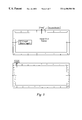
FIG. 7 is an antenna according to the invention;
FIG. 8 shows radiation patterns of the antenna of FIG. 7; and
FIG. 9 shows another antenna according to the invention.
DETAILED DESCRIPTION OF THE INVENTION
If an aperture is excited by electromagnetic waves then the field distribution in the slot can be constructed by a set of orthogonal modes. In practice for a long thin slot, such as in FIG. 1, the functions are sine-type of periodicity an integer divisor of the slot length. For instance in FIGS. 1(a) and 1(b) are illustrated the first two fundamental transverse electric modes, TE10 and TE20. For the long thin slot it is possible to excite one of these modes in preference to the others. Of importance is the frequency of operation. The TE10 mode is resonant when the slot length is ½ wavelength, while the TE20 is resonant for the slot being one wavelength long. However, when the slot is one wavelength long the actual individual mode amplitude will depend upon the excitation. For instance in FIG. 1(c) although the slot is one wavelength long and we might expect the TE20 mode to resonate, the actual field distribution corresponds to the TE10 mode, as the slot is excited in the middle, where the TE20 mode has a minimum and therefore coupling to this mode is near zero. Moving the feed to a position one quarter of the length of the slot from one end, as in FIG. 1(d), excites both the TE10 and TE20 mode, with an asymmetrical aperture field distribution. Note that the higher order modes have an insignificant effect as they are below resonance (i.e. below cut-off). To illustrate this more fully the measured change in radiation pattern with feed position of a long thin slot is shown in FIG. 2. Thus a single feed can be employed to generate two modes.
As will now be described, it is possible to use these concepts to design a multiband diversity screen antenna.
A slot antenna can be formed on the windscreen of a car as outlined in FIG. 3. A glass screen is fixed in place in a metallic aperture or frame in the vehicle body, forming a conductive margin. Usually the screen would be front or rear window as these are fixed. A long thin electrical slot is then formed between the frame and a conductive area on the screen which does not extend to the edge thereof. This may be an electrical transparent coating integrated into the screen or alternatively a grid pattern can be used, such as those used for heated screens. In the case of a gridded area it may be necessary to place additional orthogonal wires (i.e. vertical wires in the case of a horizontal rear screen heater grid) to improve the approximation, i.e. to reduce coupling across the grid loading the slot modes. This will be dependent on the pattern of the screen heater, and it is possible no additional wires may be needed in some instances.
For a rear screen of a typical saloon car the slot length is such as to support two modes, the TE10 and the TE20 (i.e. the loop length is two wavelengths) at FM frequencies (100 MHz). When a heater grid is used DC supply wires must be accommodated, which cut across the slot. If these are placed symmetrically in the middle of the sides as shown in FIG. 3, then the TE10 and TE20 modes can still be excited, as the heater wires cross at ‘nulls’—i.e. they do not load the modes significantly. Indeed they can be considered as shorting out the slot at these points so that the long thin slot of FIG. 1 effectively is bent into a U-shape. However it must be remembered the aperture fields can couple across the wires and excite fields in the lower half of the screen, which may need to be considered. Of course if no crossing wires are needed (or can be made high impedance by the use of RF chokes in the heating circuit), the nulls of the T10 and TE20 modes can be placed in various positions depending upon the feed conditions. This means that an orthogonal TE10 (‘TE01’) mode may be excited, i.e. two TE10 spaced λ/4 apart. This mode degeneracy indicates more diversity may be possible, but current discussion will be restricted to the common case of a heated rear window requiring heater wire connections as in FIG. 3.
In FIG. 3 it is seen that the TE10 mode has a maximum at the centre of the slot, while the TE20 has a maximum at the corners. Hence feeding the slot in one of these positions with a voltage probe will excite one mode in preference to the other. Placing the feed intermediate these two positions will excite both modes and the radiation pattern will differ depending upon which combination of the modes is excited, giving pattern diversity. At higher frequencies the slot is effectively longer and hence more than one mode can be excited. This leads to a greater variation in excitation and hence pattern diversity i.e. at UHF the slot can be excited at various points λ/4 apart generating different patterns.
The mode content of the aperture field depends also upon the type of feed used to excite the slot. Several types of feed are possible. In FIG. 4 three feeds are illustrated:
1. Voltage probe. Here an unbalanced feed cable is connected orthogonal to the slot, with the cable ground connected to the outside of the slot (vehicle ground) while the inner is connected to the inside edge of the slot diametrically opposite the ground connection. Here the feed voltage is equal to the aperture field voltage at this point. Note for a heater grid the feed will need to be DC isolated, using a series capacitor. Alternatively the connection to the inner area may be via a capacitive pad to provide isolation.
2. Current probe. Here the inner conductor of the feed cable is wound in the aperture and connected back to the vehicle ground. This forms a magnetic coupling to the aperture field.
3. Coplanar line probe. Here the inner conductor is extended along the centre of the slot forming a coplanar transmission line, effectively giving a capacitive voltage feed. However as it is a distributed feed the response at higher frequencies to higher order modes may differ from that of the simple voltage probe and indeed diversity may be achieved simply by feeding in the opposite direction along the slot (i.e. 3 a and 3 b).
The above indicate methods of coupling a feed line into the slot. The choice depends upon the position. The feed presents an impedance transformer into the slot modes, each slot mode has its own impedance, which is a function of feed position, frequency and mode. For instance at the centre where the TE10 has a maximum its mode impedance is close to that of the feed (50Ω), while the minimum of the TE20 indicates this mode has a low impedance. Using a voltage probe at this point will couple to the TE10 mode efficiently, but not the TE20. Using a current probe the converse can occur. The general condition is outlined by the circuit diagram of FIG. 5. Here at the feed position each mode has a different impedance, Zn. There are an infinite number of modes, but in practice only the lower dominant modes are excited. Here the lower modes will have a significant real part, while the higher order modes are predominately reactive—the real part representing radiation losses. The feed is coupled to each mode by a differing amount, symbolised by the transformer action with the number of turns, Nn, differing according to the amount of coupling to each mode. Finally the source impedance of the system, Zo, is shown connected through a matching circuit. At any feed point any mode can be excited, however the match circuit can only be optimised to match to one mode. However if modes present similar impedances then more than one can be excited. Hence position, matching and the feed type all play a part in deciding the modal contribution, and hence the radiation pattern.
FIG. 6 shows how two feeds may be used to extract several different diversity signals from a slot antenna excited in more than one mode. One feed is central of the slot to excite the TE10 mode, and the other is part way along it and positioned to excite principally the TE20 mode. As the modes are orthogonal the two feeds are weakly coupled, i.e. both can be used simultaneously. In this instance they are used both independently and combined together electronically to provide greater diversity. The outputs from the antenna are summed together or differenced. In the simplest case this would provide (Ant 1), (Ant 1+Ant 2) and (Ant 1−Ant 2), the difference being obtained by inserting a 180° phase shift in one line using a λ/4 line, or an appropriate L-C network, and then summing. In FIG. 6, “A” represents signal Amplitude, and “φ” represents signal Phase, both of which may be adjusted by the “Control.”
Also shown in FIG. 6 is the use of filters to separate FM and TV signals; here the same feeds are being used to provide the TV antennas as well as the FM antennas. The situation at higher frequencies becomes more complicated as a large number of modes can be excited. However it is found that if the feeds are spaced apart by more than one wavelength they are invariably independent, i.e. there is minimal loading of one antenna on another.
Above it was noted that wires could be run across the slot at points where there are field minima without affecting the antenna performance. A further development from this is to switch in wires across points of maximum field to load one mode significantly. If the feed is kept fixed, the aperture distribution can be significantly modified, and hence the radiation pattern. For instance, shorting across one comer in FIG. 3 will load the TE10 and TE20 modes to differing degrees, resulting in pattern diversity.
A typical screen antenna based upon this approach is illustrated in FIG. 7. Here a rear screen with a printed heater grid is modified to provide effectively four FM diversity antennas, one AM antenna, one Band I TV antenna (50 MHz), four Band III/IV/V TV antennas (170-220 MHz, 470-860 MHz) with options for Remote Access (315 MHz/433 MHz) and Weatherband (162 MHz).
The slot is formed between the heater grid and the window aperture in the vehicle. The heater grid and its connections are RF grounded by means of a capacitor connected between the window frame and the grid, forming a U-shaped slot the length of which is approximately λ/2 at 50 MHz. Hence at 100 MHz there are two modes which can be excited.
Feeds 1 and 2 provide two weakly coupled feeds A and B for FM (88-108 MHz), a quarter of wavelength apart. The switching and combining technique shown by FIG. 6 is used to generate pattern diversity. In this instance equal amplitudes but different phase shifts are used in the combining, with values of 0°, 180°, +90° and −90°, to provide A, B, (A+B), (A−B), (A+jB) and (A−jB). The phase shift can be realized by various methods such as switching in additional transmission line lengths or the use of L-C all-pass filters.
FIG. 8 shows the resulting polar radiation patterns; six different radiation patterns are obtained from two feeds. Nulls can be moved or even created, bringing advantages in diversity operation, and simplifying design for diversity.
Feeds 1 and 2 are re-used at other frequencies together with feeds 3 and 4, to provide the TV, remote access and weatherband antennas. Feed 3 is a transmission-line type feed and feed 4 is complementary to feed 1 but at least in this example is utilised only at higher frequencies. These feeds provide additional spatial diversity at the higher frequencies, although some matching may be required on some ports. Simple L-C filtering splits the signals to provide the four TV, weatherband and remote access antennas. These splitter circuits need to be mounted at the antenna feed, hence the provision of a ground plane along the top of the screen. These could potentially be mounted on the inside of the car body but at increased cost. The ground area can be utilised for the mounting of amplifiers, diversity control electronics etc., minimising the number of cables coming off the screen. At 50 MHz there is only one mode, hence no diversity is possible although one antenna can be provided via feed 2. Finally the slot cannot be used for AM as it is too short at these frequencies (<2 MHz). An AM antenna is provided by the second pair of lines in the second top half of the slot to complement the wire pattern of Feed 3. The result is a simple wire pattern, which can be printed on the screen for ease of production, and is visually pleasing yet provides nearly all of the antenna requirements of the modern vehicle designer. This embodiment also demonstrates an incidental advantage over known systems in which the grid itself is used as an antenna. In such systems an expensive coil is needed to provide RF isolation of the grid from the car body whilst still permitting the supply of heater current. Here because the grid is RF grounded rather than RF isolated, only an inexpensive capacitor is required.
Mobile phones are required to transmit as well as receive. Current digital phone technology requires the transmission of quite high RF peak powers (8 W at the antenna). Correspondingly there are concerns about the level of RF radiation inside the passenger compartment. A usual arrangement for the mobile phone antenna is a monopole rod antenna placed centrally on the roof towards the rear screen, or indeed placed on the rear screen, using a capacitive coupling through the glass. In this instance a grid is usually placed near the base of the mobile phone antenna, to increase the local ground, reducing radiation into the car. This conflicts with the need to provide an aperture near the edge of the screen for the diversity slot antenna. However the frequencies involved are an order of magnitude apart and a compromise can therefore be reached as illustrated in FIG. 9. Here the slot width is reduced by a local grid, which connects to the central conductive area (i.e. heater grid). The grid width is approximately λ/2 at the mobile phone frequency (900 MHz or 1800 MHz typically). The slot width at the top is sufficient such that the grid does not short the slot, but will introduce a small capacitive loading. In practice a 10 to 20 mm gap appears to have little effect on the slot modes at FM frequencies. FM feed can be made by connecting to the grid, as indicated in FIG. 9. Here two feeds as shown either side of the phone antenna base. Although each gives a similar antenna pattern there are advantages in that one can be used for FM and one for TV, easing the circuit functions in splitting the bands.

Claims (17)

What is claimed is:
1. A road vehicle antenna comprising a slot defined by an aperture in an electrically-conductive structure of a vehicle body and a further electrically-conductive structure disposed within said aperture, the antenna having a plurality of antenna feeds electrically coupled to the slot, wherein at least one of said antenna feeds is coupled to the slot at a position where a first excitation mode of the slot and at least one higher-order excitation mode of the slot each have a non-null value, the antenna also comprising controllable combining means for controllably combining said antenna feeds so that in use the antenna exhibits a number of selectable radiation patterns in excess of the number of feeds.
2. The antenna of claim 1, wherein the slot is of a length equal to one or one-half wavelength of the first excitation mode.
3. The antenna of claim 1, wherein the slot is U-shaped.
4. The antenna of claim 1, wherein the at least one of the antenna feeds is coupled to the slot at a position approximating the position at which the at least one higher-order excitation mode has a maximum value.
5. The antenna of claim 1, wherein conductors of said antenna feeds are electrically conducted to an inside edge of the slot.
6. The antenna of claim 1, wherein one or more of said antenna feeds is reactively (capacitively or inductively) coupled to the antenna.
7. The antenna of claim 1, wherein the at least one antenna feed is electrically connected to the slot at a position where TE10, as the first excitation mode of the slot, and TE20, as the at least one higher-order excitation mode of the slot, each have a non-null value.
8. The antenna of claim 1, wherein the controllable combining means includes a control means and a means for summing and/or differencing at least two of said antenna feeds.
9. The antenna of claim 8, wherein the controllable combining means comprises means for phase-shifting at least one of said antenna feeds.
10. The antenna of claim 1, comprising means for short-circuiting a portion of the slot to load an excitation mode.
11. The antenna of claim 10, wherein the short-circuit means comprises a conductor bridging the slot between the electrically-conductive structure and the further electrically-conductive structure.
12. The antenna of claim 10, wherein the short-circuit means is disposed at a position of maximum field strength in the slot.
13. The antenna of claim 1, wherein the further electrically-conductive structure comprises a conductive region or pattern carried by a dielectric substrate.
14. The antenna of claim 13, wherein the substrate forms a window or body panel.
15. The antenna of claim 1, wherein the controllable combining means includes means for open-circuiting one or more of said antenna feeds.
16. The antenna of claim 14, wherein the substrate comprises a ground plane in which signal splitting, filtering, processing or conditioning circuits are disposed.
17. The antenna of claim 1, configured for, at least, FM signals, and also including a separate portion for receiving broadcast AM signals.
US09/719,801 1998-06-17 1999-06-11 Multiband vehicle antenna Expired - Fee Related US6498588B1 (en)

Applications Claiming Priority (3)

Application Number Priority Date Filing Date Title
GB9813129 1998-06-17
GBGB9813129.5A GB9813129D0 (en) 1998-06-17 1998-06-17 Multiband vehicle screen antenna
PCT/GB1999/001856 WO1999066587A1 (en) 1998-06-17 1999-06-11 Multiband vehicle antenna

Publications (1)

Publication Number Publication Date
US6498588B1 true US6498588B1 (en) 2002-12-24

Family

ID=10833959

Family Applications (1)

Application Number Title Priority Date Filing Date
US09/719,801 Expired - Fee Related US6498588B1 (en) 1998-06-17 1999-06-11 Multiband vehicle antenna

Country Status (7)

Country Link
US (1) US6498588B1 (en)
EP (1) EP1088365B1 (en)
JP (1) JP2002518919A (en)
AU (1) AU4282699A (en)
DE (1) DE69913962T2 (en)
GB (1) GB9813129D0 (en)
WO (1) WO1999066587A1 (en)

Cited By (12)

* Cited by examiner, † Cited by third party
Publication number Priority date Publication date Assignee Title
EP1530253A1 (en) * 2003-11-04 2005-05-11 Nippon Sheet Glass Co.,Ltd. Glass antenna and glass antenna system for vehicles
FR2866155A1 (en) * 2004-02-06 2005-08-12 Composants Electr Soc D Screened antenna system for use in e.g. four door sedan, has frequency modulation antennae whose aerials have vertical lines, where antennae signals are collected at points to acquire directive signal in vehicle length and width directions
US20070279301A1 (en) * 2003-12-05 2007-12-06 Markus Hoffmeister Window-Integrated Antenna in Vehicles
US20080055169A1 (en) * 2003-12-17 2008-03-06 Robert Bosch Gmbh Window-Integrated Antenna In Vehicles
US20080129635A1 (en) * 2006-12-04 2008-06-05 Agc Automotive Americas R&D, Inc. Method of operating a patch antenna in a higher order mode
US20080129636A1 (en) * 2006-12-04 2008-06-05 Agc Automotive Americas R&D, Inc. Beam tilting patch antenna using higher order resonance mode
US8009111B2 (en) 1999-09-20 2011-08-30 Fractus, S.A. Multilevel antennae
US8466842B2 (en) 2010-10-22 2013-06-18 Pittsburgh Glass Works, Llc Window antenna
US8738103B2 (en) 2006-07-18 2014-05-27 Fractus, S.A. Multiple-body-configuration multimedia and smartphone multifunction wireless devices
WO2018029273A1 (en) * 2016-08-10 2018-02-15 Fuba Automotive Electronics Gmbh Active antenna arrangement for radio reception in the cut-out of an electrically conductive vehicle body
WO2018111794A1 (en) * 2016-12-12 2018-06-21 AMI Research & Development, LLC Am/fm directional antenna array for vehicle
US11048786B2 (en) 2016-04-13 2021-06-29 AMI Research & Development, LLC Techniques for fingerprint detection and user authentication

Families Citing this family (10)

* Cited by examiner, † Cited by third party
Publication number Priority date Publication date Assignee Title
US6388631B1 (en) * 2001-03-19 2002-05-14 Hrl Laboratories Llc Reconfigurable interleaved phased array antenna
DE10146439C1 (en) 2001-09-20 2002-11-28 Pilkington Automotive D Gmbh Automobile antenna window panel has elongate dielectric slit between central conductive surface and metallic edge enclosing window panel
US6965349B2 (en) 2002-02-06 2005-11-15 Hrl Laboratories, Llc Phased array antenna
FR2856858B1 (en) * 2003-06-27 2008-12-12 Johnson Controls Tech Co TRANSMITTER RECEIVER A AUTO LEARNING
WO2006021627A1 (en) * 2004-07-27 2006-03-02 Johnson Controls Technology Company Self-learning transceiver
US7126539B2 (en) 2004-11-10 2006-10-24 Agc Automotive Americas R&D, Inc. Non-uniform dielectric beam steering antenna
US7119751B2 (en) 2005-03-11 2006-10-10 Agc Automotive Americas R&D, Inc. Dual-layer planar antenna
DE102005039914A1 (en) 2005-08-24 2007-03-08 Robert Bosch Gmbh Multi-range antenna array
DE102009040296A1 (en) * 2009-09-04 2011-03-10 Bayerische Motoren Werke Aktiengesellschaft Motor vehicle, has filter whose outlet is connected with input of multiple-input multiple-output module, where multiple-input multiple-output service uses signals in region at another outlet of filter and region at outlet of another filter
US8576130B2 (en) * 2010-10-22 2013-11-05 Pittsburgh Glass Works, Llc Wideband antenna

Citations (11)

* Cited by examiner, † Cited by third party
Publication number Priority date Publication date Assignee Title
JPS59196606A (en) 1983-04-22 1984-11-08 Sumitomo Electric Ind Ltd U-shaped on-vehicle tv antenna
US4721963A (en) * 1986-07-25 1988-01-26 General Motors Corporation Vehicle roof mounted slot antenna with separate AM and FM feeds
EP0375415A2 (en) 1988-12-23 1990-06-27 Harada Industry Co., Ltd. Plane slot antennas and their use in motor vehicles
EP0375416A2 (en) 1988-12-23 1990-06-27 Harada Industry Co., Ltd. Plane slot antenna
DE4125898A1 (en) 1991-08-05 1993-02-11 Hirschmann Richard Gmbh Co VEHICLE ANTENNA
EP0561272A1 (en) 1992-03-16 1993-09-22 Ppg Industries, Inc. Transparent window antenna
DE19513263A1 (en) 1995-04-07 1996-10-10 Lindenmeier Heinz Antenna arrangement on a window with high heat transmission loss
EP0760537A2 (en) 1995-09-02 1997-03-05 FLACHGLAS Automotive GmbH Glass antenna for vehicle window
US5714961A (en) 1993-07-01 1998-02-03 Commonwealth Scientific And Industrial Research Organisation Planar antenna directional in azimuth and/or elevation
DE19730173A1 (en) 1997-07-15 1999-01-21 Fuba Automotive Gmbh Plastic vehicle body with antennas
EP0899811A2 (en) 1997-08-19 1999-03-03 Harada Industry Co., Ltd. All-around vehicle antenna-apparatus

Patent Citations (12)

* Cited by examiner, † Cited by third party
Publication number Priority date Publication date Assignee Title
JPS59196606A (en) 1983-04-22 1984-11-08 Sumitomo Electric Ind Ltd U-shaped on-vehicle tv antenna
US4721963A (en) * 1986-07-25 1988-01-26 General Motors Corporation Vehicle roof mounted slot antenna with separate AM and FM feeds
EP0375415A2 (en) 1988-12-23 1990-06-27 Harada Industry Co., Ltd. Plane slot antennas and their use in motor vehicles
EP0375416A2 (en) 1988-12-23 1990-06-27 Harada Industry Co., Ltd. Plane slot antenna
DE4125898A1 (en) 1991-08-05 1993-02-11 Hirschmann Richard Gmbh Co VEHICLE ANTENNA
EP0561272A1 (en) 1992-03-16 1993-09-22 Ppg Industries, Inc. Transparent window antenna
US5714961A (en) 1993-07-01 1998-02-03 Commonwealth Scientific And Industrial Research Organisation Planar antenna directional in azimuth and/or elevation
DE19513263A1 (en) 1995-04-07 1996-10-10 Lindenmeier Heinz Antenna arrangement on a window with high heat transmission loss
EP0760537A2 (en) 1995-09-02 1997-03-05 FLACHGLAS Automotive GmbH Glass antenna for vehicle window
US5898407A (en) * 1995-09-02 1999-04-27 Flachglas Automotive Gmbh Motor vehicle with antenna window with improved radiation and reception characteristics
DE19730173A1 (en) 1997-07-15 1999-01-21 Fuba Automotive Gmbh Plastic vehicle body with antennas
EP0899811A2 (en) 1997-08-19 1999-03-03 Harada Industry Co., Ltd. All-around vehicle antenna-apparatus

Non-Patent Citations (1)

* Cited by examiner, † Cited by third party
Title
Kitsuregawa et al., Antenna Beam Shifting by Dual Modes, Aug. 21, 1996, Summary and Introduction.

Cited By (37)

* Cited by examiner, † Cited by third party
Publication number Priority date Publication date Assignee Title
US9000985B2 (en) 1999-09-20 2015-04-07 Fractus, S.A. Multilevel antennae
US8009111B2 (en) 1999-09-20 2011-08-30 Fractus, S.A. Multilevel antennae
US8154463B2 (en) 1999-09-20 2012-04-10 Fractus, S.A. Multilevel antennae
US9761934B2 (en) 1999-09-20 2017-09-12 Fractus, S.A. Multilevel antennae
US8154462B2 (en) 1999-09-20 2012-04-10 Fractus, S.A. Multilevel antennae
US9362617B2 (en) 1999-09-20 2016-06-07 Fractus, S.A. Multilevel antennae
US9240632B2 (en) 1999-09-20 2016-01-19 Fractus, S.A. Multilevel antennae
US9054421B2 (en) 1999-09-20 2015-06-09 Fractus, S.A. Multilevel antennae
US10056682B2 (en) 1999-09-20 2018-08-21 Fractus, S.A. Multilevel antennae
US8976069B2 (en) 1999-09-20 2015-03-10 Fractus, S.A. Multilevel antennae
US8941541B2 (en) 1999-09-20 2015-01-27 Fractus, S.A. Multilevel antennae
US8330659B2 (en) 1999-09-20 2012-12-11 Fractus, S.A. Multilevel antennae
US7071886B2 (en) 2003-11-04 2006-07-04 Nippon Sheet Glass Company, Limited Glass antenna and glass antenna system for vehicles
EP1530253A1 (en) * 2003-11-04 2005-05-11 Nippon Sheet Glass Co.,Ltd. Glass antenna and glass antenna system for vehicles
US20050128153A1 (en) * 2003-11-04 2005-06-16 Ryokichi Doi Glass antenna and glass antenna system for vehicles
US20070279301A1 (en) * 2003-12-05 2007-12-06 Markus Hoffmeister Window-Integrated Antenna in Vehicles
US7719475B2 (en) 2003-12-17 2010-05-18 Robert Bosch Gmbh Window-integrated antenna in vehicles
US20080055169A1 (en) * 2003-12-17 2008-03-06 Robert Bosch Gmbh Window-Integrated Antenna In Vehicles
US20070120754A1 (en) * 2004-02-06 2007-05-31 Societe De Composants Electriques Serigraphed antenna for the rear window of a saloon-type car
US7348927B2 (en) 2004-02-06 2008-03-25 Societe De Composants Electriques Serigraphed antenna for the rear window of a saloon-type car
FR2866155A1 (en) * 2004-02-06 2005-08-12 Composants Electr Soc D Screened antenna system for use in e.g. four door sedan, has frequency modulation antennae whose aerials have vertical lines, where antennae signals are collected at points to acquire directive signal in vehicle length and width directions
WO2005078857A1 (en) * 2004-02-06 2005-08-25 Societe De Composants Electriques Serigraphed antenna for the rear window of a saloon-type car
US11735810B2 (en) 2006-07-18 2023-08-22 Fractus, S.A. Multiple-body-configuration multimedia and smartphone multifunction wireless devices
US8738103B2 (en) 2006-07-18 2014-05-27 Fractus, S.A. Multiple-body-configuration multimedia and smartphone multifunction wireless devices
US11031677B2 (en) 2006-07-18 2021-06-08 Fractus, S.A. Multiple-body-configuration multimedia and smartphone multifunction wireless devices
US9099773B2 (en) 2006-07-18 2015-08-04 Fractus, S.A. Multiple-body-configuration multimedia and smartphone multifunction wireless devices
US11349200B2 (en) 2006-07-18 2022-05-31 Fractus, S.A. Multiple-body-configuration multimedia and smartphone multifunction wireless devices
US10644380B2 (en) 2006-07-18 2020-05-05 Fractus, S.A. Multiple-body-configuration multimedia and smartphone multifunction wireless devices
US9899727B2 (en) 2006-07-18 2018-02-20 Fractus, S.A. Multiple-body-configuration multimedia and smartphone multifunction wireless devices
US20080129635A1 (en) * 2006-12-04 2008-06-05 Agc Automotive Americas R&D, Inc. Method of operating a patch antenna in a higher order mode
US7505002B2 (en) 2006-12-04 2009-03-17 Agc Automotive Americas R&D, Inc. Beam tilting patch antenna using higher order resonance mode
US20080129636A1 (en) * 2006-12-04 2008-06-05 Agc Automotive Americas R&D, Inc. Beam tilting patch antenna using higher order resonance mode
US8466842B2 (en) 2010-10-22 2013-06-18 Pittsburgh Glass Works, Llc Window antenna
US11048786B2 (en) 2016-04-13 2021-06-29 AMI Research & Development, LLC Techniques for fingerprint detection and user authentication
WO2018029273A1 (en) * 2016-08-10 2018-02-15 Fuba Automotive Electronics Gmbh Active antenna arrangement for radio reception in the cut-out of an electrically conductive vehicle body
WO2018111794A1 (en) * 2016-12-12 2018-06-21 AMI Research & Development, LLC Am/fm directional antenna array for vehicle
US10714819B2 (en) 2016-12-12 2020-07-14 AMI Research & Development, LLC AM/FM directional antenna array for vehicle

Also Published As

Publication number Publication date
EP1088365A1 (en) 2001-04-04
EP1088365B1 (en) 2004-01-02
JP2002518919A (en) 2002-06-25
DE69913962T2 (en) 2004-12-09
WO1999066587A1 (en) 1999-12-23
DE69913962D1 (en) 2004-02-05
GB9813129D0 (en) 1998-08-19
AU4282699A (en) 2000-01-05

Similar Documents

Publication Publication Date Title
US6498588B1 (en) Multiband vehicle antenna
US5198826A (en) Wide-band loop antenna with outer and inner loop conductors
US7142162B2 (en) Antenna structure and television receiver
US6853341B1 (en) Antenna means
CA1287916C (en) Near-isotropic low-profile microstrip radiator especially suited for use as a mobile vehicle antenna
KR100411638B1 (en) A glass antenna apparatus for a vehicle
EP0872912B1 (en) Circular-polarization antenna
EP0757405B1 (en) Antenna
US6133879A (en) Multifrequency microstrip antenna and a device including said antenna
EP1368855B1 (en) Antenna arrangement
US7423591B2 (en) Antenna system
US5610619A (en) Backlite antenna for AM/FM automobile radio having broadband FM reception
JPH09260925A (en) Antenna system
EP0783774B1 (en) Antenna
WO1997049142A1 (en) Circular-polarisation two-way antenna
EP0824766A1 (en) Antenna unit
US5790079A (en) Backlite antenna for AM/FM automobile radio
JP4112136B2 (en) Multi-frequency antenna
US20200168983A1 (en) Coaxial Helix Antennas
JP3181075B2 (en) Mobile antenna
US4804968A (en) Vehicle antenna system
WO2005060046A2 (en) Concealed vehicle antenna utilizing body panel slot
JP2000196337A (en) Antenna system
JPH08107306A (en) Diversity antenna
JP5633295B2 (en) Vehicle antenna

Legal Events

Date Code Title Description
AS Assignment

Owner name: HARADA INDUSTRIES (EUROPE) LIMITED, UNITED KINGDOM

Free format text: ASSIGNMENT OF ASSIGNORS INTEREST;ASSIGNOR:CALLAGHAN, PETER;REEL/FRAME:011606/0394

Effective date: 20010214

AS Assignment

Owner name: HARADA INDUSTRY CO., LTD., JAPAN

Free format text: ASSIGNMENT OF ASSIGNORS INTEREST;ASSIGNOR:HARADA INDUSTRIES (EUROPE) LIMITED;REEL/FRAME:016164/0053

Effective date: 20030930

FPAY Fee payment

Year of fee payment: 4

REMI Maintenance fee reminder mailed
LAPS Lapse for failure to pay maintenance fees
STCH Information on status: patent discontinuation

Free format text: PATENT EXPIRED DUE TO NONPAYMENT OF MAINTENANCE FEES UNDER 37 CFR 1.362