US6500200B1 - Heat exchanger garment - Google Patents
Heat exchanger garment Download PDFInfo
- Publication number
- US6500200B1 US6500200B1 US09/582,849 US58284900A US6500200B1 US 6500200 B1 US6500200 B1 US 6500200B1 US 58284900 A US58284900 A US 58284900A US 6500200 B1 US6500200 B1 US 6500200B1
- Authority
- US
- United States
- Prior art keywords
- garment
- heat exchanger
- fluid
- layers
- exchanger according
- Prior art date
- Legal status (The legal status is an assumption and is not a legal conclusion. Google has not performed a legal analysis and makes no representation as to the accuracy of the status listed.)
- Expired - Lifetime
Links
Images


Classifications
-
- A—HUMAN NECESSITIES
- A61—MEDICAL OR VETERINARY SCIENCE; HYGIENE
- A61F—FILTERS IMPLANTABLE INTO BLOOD VESSELS; PROSTHESES; DEVICES PROVIDING PATENCY TO, OR PREVENTING COLLAPSING OF, TUBULAR STRUCTURES OF THE BODY, e.g. STENTS; ORTHOPAEDIC, NURSING OR CONTRACEPTIVE DEVICES; FOMENTATION; TREATMENT OR PROTECTION OF EYES OR EARS; BANDAGES, DRESSINGS OR ABSORBENT PADS; FIRST-AID KITS
- A61F7/00—Heating or cooling appliances for medical or therapeutic treatment of the human body
- A61F7/02—Compresses or poultices for effecting heating or cooling
-
- A—HUMAN NECESSITIES
- A61—MEDICAL OR VETERINARY SCIENCE; HYGIENE
- A61F—FILTERS IMPLANTABLE INTO BLOOD VESSELS; PROSTHESES; DEVICES PROVIDING PATENCY TO, OR PREVENTING COLLAPSING OF, TUBULAR STRUCTURES OF THE BODY, e.g. STENTS; ORTHOPAEDIC, NURSING OR CONTRACEPTIVE DEVICES; FOMENTATION; TREATMENT OR PROTECTION OF EYES OR EARS; BANDAGES, DRESSINGS OR ABSORBENT PADS; FIRST-AID KITS
- A61F7/00—Heating or cooling appliances for medical or therapeutic treatment of the human body
- A61F2007/0001—Body part
-
- A—HUMAN NECESSITIES
- A61—MEDICAL OR VETERINARY SCIENCE; HYGIENE
- A61F—FILTERS IMPLANTABLE INTO BLOOD VESSELS; PROSTHESES; DEVICES PROVIDING PATENCY TO, OR PREVENTING COLLAPSING OF, TUBULAR STRUCTURES OF THE BODY, e.g. STENTS; ORTHOPAEDIC, NURSING OR CONTRACEPTIVE DEVICES; FOMENTATION; TREATMENT OR PROTECTION OF EYES OR EARS; BANDAGES, DRESSINGS OR ABSORBENT PADS; FIRST-AID KITS
- A61F7/00—Heating or cooling appliances for medical or therapeutic treatment of the human body
- A61F2007/0054—Heating or cooling appliances for medical or therapeutic treatment of the human body with a closed fluid circuit, e.g. hot water
-
- A—HUMAN NECESSITIES
- A61—MEDICAL OR VETERINARY SCIENCE; HYGIENE
- A61F—FILTERS IMPLANTABLE INTO BLOOD VESSELS; PROSTHESES; DEVICES PROVIDING PATENCY TO, OR PREVENTING COLLAPSING OF, TUBULAR STRUCTURES OF THE BODY, e.g. STENTS; ORTHOPAEDIC, NURSING OR CONTRACEPTIVE DEVICES; FOMENTATION; TREATMENT OR PROTECTION OF EYES OR EARS; BANDAGES, DRESSINGS OR ABSORBENT PADS; FIRST-AID KITS
- A61F7/00—Heating or cooling appliances for medical or therapeutic treatment of the human body
- A61F7/02—Compresses or poultices for effecting heating or cooling
- A61F2007/0282—Compresses or poultices for effecting heating or cooling for particular medical treatments or effects
- A61F2007/0288—Compresses or poultices for effecting heating or cooling for particular medical treatments or effects during operations
Definitions
- the present invention relates to a heat exchanger which is intended to be applied onto a subject's body for controlling the subject's body temperature during medical procedure.
- U.S. Pat. No. 4,844,072 describes a system which may be used in thermal therapy and which includes a thermal pad with internal channels for carrying a temperature-control liquid therethrough.
- a thermal bandage which achieves a similar purpose is described in U.S. Pat. No. 4,962,761 through which heat control liquid is circulated when placed in contact with the body.
- several such matters may be placed in series and fitted into a planar array or into a garment.
- U.S. Pat. No. 5,269,369 discloses a temperature regulation system for human body which makes use of heat pipes which are incorporated into a garment, which distributes energy to and from portions of the human body.
- a tube laminated heat transfer article for placing against a human body for transfer heat to or from the human body is disclosed in U.S. Pat. No. 5,755,275.
- a heating and/or cooling pad having the shape of the human body which is placed beneath the patient to allow heat or cold to radiate upwards is disclosed in U.S. Pat. No. 5,785,716.
- MicroClimate Systems Inc. Stanford, Mich., U.S.A., markets a series of portable personal cooling systems (sold under the trademarks KOOLVEST, KOOLJACKET, KOOLBAND, KOOLPAID and others) which are intended for use by healthy persons who perform a physical activity in a hot environment (see Internet http://www.microclimate.com/prodline.html or http://www.microclimate.com/work.html).
- the system consists of a garment (it may be a vest, jacket, skull cap, a cervical collar, etc.) with tubing embedded therein in which water flows propelled by a battery-powered pump. Water passes through ice or through a cooling device before entering the tubing within the garment.
- the user can control the pump rate, the temperature, etc.
- a similar product line is also provided by Mallinckrodt Inc., St. Louis, Mo., U.S.A. (see the Internet at http://www/mallinckrodt.com/ccd) and others.
- a heat exchanger in the form of a garment which is highly effective in transferring a heat to or from a subject's body in order to control the subject's body temperature has been developed.
- the invention thus provides, a heat exchanger for use in controlling a subject's body temperature during a medical procedure, comprising:
- a flexible garment adapted for enveloping portions of the subject's body surface, the garment having dedicated sections for enveloping different body parts which comprise a torso section for enveloping substantial portions of the subject's torso and one or more extremity sections for enveloping portions of one or more of the individual's extremities;
- fluid-tight space defined between an internal, body-facing layer of the garment and an external layer and between fluid tight edges of the garment, the faces of both layers lining said space being attached to one another along lines defining a flow path between at least one fluid inlet and at least one fluid outlet to permit flow of fluid from the at least one inlet to the at least one outlet throughout essentially the entire garment for effective heat transfer to or from all parts of the garment;
- the inner faces of the garment's internal and external layers are made of a heat-weldable material and are point welded to one another at a plurality of locations throughout the garment.
- the fluid-tight space which is defined between the internal and the external layers of the garment, has typically a volume per unit area which is essentially the same throughout the entire garment.
- the point welds may be randomly distributed throughout the garment or may be arranged in an ordered array.
- a typical distance between two adjacent welded points in the garment is between about 8 to about 20 mm.
- the garment is typically designed for working under fluid pressure of about 0.5-1.5 atmospheres.
- the space is formed such that under a pressure of this range the space's volume per unit area of the garment is in the range of about 1-3 liter/m 2 of garment surface.
- a preferred heat exchanger in accordance with the invention is such wherein each of the internal and the external layers is constructed of two layers; namely the garment is a four-layered structure.
- This four-layered structure consists of two impermeble sheets lining said space overlaid by usually heavier reinforcing layers. All four layers are typically made of a heat-weldable material and are point welded to one another.
- the two innermost layers serve to define the fluid-tight space, while the outer layers reinforce the structure and allow the application of an increased internal fluid pressure, at times up to about 3 Atm without rupturing. Increase pressure may at times be of importance to ensure a certain level of flow of the heat-control fluid within the garment's inner space.
- the inner layers of the heat exchange may be made of a polyethylene-based material such as Metallocene (manufactured by Dow Chemicals) sheeting, typically but not restricted to about 20-50 ⁇ m thickness.
- the two outer layers are preferably somewhat hydrophilic to allow a certain degree of absorption of body and/or cleaning and disinfecting fluids and are also preferably soft to touch to ensure improved patient's comfort when contacting the skin.
- the outer layers may, for example, be made of a woven or non-woven spunbond fabric, e.g. made of polypropylene, having a characteristic weight of about 20 g/m 2 to about 50 g/m 2 .
- the welding together of the four layers may be achieved, for example, by means of RF welding.
- the heat exchanger having the aforementioned characteristics is novel by itself (even when not formed into a garment as defined above), and forms an aspect of the present invention.
- the heat exchanger may be used for any application requiring a flexible heat exchanger with a relatively large heat exchange surface.
- a significant feature of the heat exchanger of this embodiment is that it is of low cost and high efficiency and has overall performance (heat exchange properties, flexibility, internal pressure resistance, and others) hitherto attained only with more complex and costly devices.
- the heat transfer fluid is typically a liquid, e.g. water.
- a heat exchanger which is adapted for use with a liquid heat transfer fluid, typically made to circulate by a pump, is made with an internal flow resistance within the space such that under a pressure differential between the input and output of about 0.5 atmospheres, the flow rate through the garment will be in the range of about 0.5-2 liter/minute, typically about 1 liter/minute.
- the garment is preferably designed such that each different section can be manipulated independently from other sections between an enveloping and a non-enveloping state.
- This has several advantages. For one, it allows easy accessibility to different parts of the body. Furthermore, this allows to use a single type of garment for different kinds of operations: for example in case of an operation performed on the subject's leg, the respective section will obviously be in the non-enveloping state while the other sections, namely those of the torso, the other leg, the arms, the neck, the head, etc., may be in an enveloping state.
- the feature of independent manipulation of the different sections between an enveloping and a non-enveloping state is typically achieved by emarginations in the garment's edges.
- the garment may also have a modular design. For example, there may be a garment piece designed for the torso, a garment piece designed for the head, a garment piece designed for the legs or arms, etc.
- the different garment pieces may be combined to form a garment in a manner to meet specific needs.
- the heat exchanger of the invention is particularly useful in controlling the body temperature of a patient during surgery.
- the heat exchanger in accordance with the invention may be designed for all shapes and sizes of human subjects as well as for animals.
- FIG. 1 is a top planar view of a garment in accordance with an embodiment of the invention.
- FIG. 2A is an enlargement of the region marked “II” in FIG. 1 with the internal and external layers being partially separated for illustrative purposes.
- FIG. 2B is a cross-section through line B—B of FIG. 2 A.
- FIG. 3A shows an embodiment of a heat exchanger in accordance with an aspect of the invention, with one comer being opened to illustrate its four-layered construction.
- This heat exchanger is useful, in accordance with a preferred embodiment of the invention, in the garment of the invention.
- FIG. 3B is a cross-section through lines III—III in FIG. 3 A.
- FIG. 4 is a schematic illustration of a garment in accordance with an embodiment of the invention applied to a patient.
- FIG. 5 is a side elevation of the patient with the garment of FIG. 3 .
- FIG. 6 is a top planar view of a garment in accordance with another embodiment of the invention.
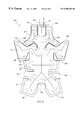
- FIG. 7 shows the top portion of the garment as applied over a patient's head.
- FIG. 8 shows a top elevational view of a garment in accordance with an embodiment of the invention adapted for use for dogs.
- FIG. 1 showing a planar view of a garment generally designated 20 of which a part marked “II” in FIG. 1 is shown in a more enlarged view in FIG. 2 A and of which a cross-section through lines B—B of FIG. 2A is shown in FIG. 2 B.
- the garment has an internal, body-facing layer 22 and an external layer 24 which define between them a fluid-tight space 26 .
- Each of the layers 22 , 24 is made from a thermoplastic material with a heat weldable, space-lining face 28 , 30 (see FIG. 2 B). The two layers are welded to one another in fluid tight manner at the edges 32 .
- the two layers 22 , 24 are welded to one another at a plurality of weld points 40 seen in FIGS. 2A and 2B.
- the weld points 40 cause a flow disturbance and consequently the flow of liquid through the garment (see description below) becomes uniform throughout the entire space of the flow path (see below).
- the garment is symmetrical along a longitudinal midline which is a typical, but not exclusive case. Occasionally, garments for a variety of uses may also be made to be non symmetrical. As can be seen, the garment has a variety of dedicated sections a, b, c, d and e on both the left and right sides of the garment. The different sections are defined by the general shape of the garment as well as by emarginations 50 , 52 , 54 , 56 and 58 , part of which are in the form of lateral indentations while others are in the form of slits.
- Section a is intended for enveloping portions of the individual's neck and head
- section b is for portions of the individual's arms
- section c is for side portions of the individual's torso
- section d is for the hip and thigh while section e is for the shin.
- the garment is provided with a fluid inlet 60 and a fluid outlet 62 , which in this specific embodiment are fitted into section a.
- a fluid inlet 60 and a fluid outlet 62 which in this specific embodiment are fitted into section a.
- the outlet and inlet may be fitted into any other section, at times conveniently into section e at times conveniently into section c, etc.
- a flow path represented by a series of consecutive arrowed lines 66 is defined by means of flow path-defining weld lines, which are designated collectively by the numeral 68 .
- These weld lines are formed by heat welding as generally known per se.
- the garment 20 may be provided with integral fastening means, e.g. hook and pile-type fasteners (see FIG. 4) or adhesive or pressure-sensitive patches (see FIG. 6 ).
- the fastening means may be applied prior to fitting the garment on the patient: for example, a two-sided patch may then be attached to the internal layer of the garment; separate straps or buckles, etc. may be added. All such fastening means are generally known per se.
- FIGS. 3A and 3B showing a heat exchanger 300 having a fluid inlet 301 and a fluid outlet 302 for the transfer of heat exchange fluid through internal space 303 formed within the heat exchanger and confined by weld lines 304 .
- Fluid inlet 301 and fluid outlet 302 are connected, respectively, to a fluid supply tube and to a fluid drainage tube which are in turn connected to a system which supplies the cooling fluid.
- Fluid space 303 is defined between two fluid tight sheets or films 305 and 306 which are overlaid by respective outside layers 307 and 308 .
- Sheets 305 and 306 are typically polyethylene sheets such as Metallocene PE (manufactured by Dow Elanco, USA) and layers 307 and 308 are made of non-woven polypropylene spunbond fabric of the characteristic weight of about 30-40 gm/m 2 .
- the external layers can be made to other specifications to meet any desired characteristics. They may have different characteristic weights, different textures, etc., to provide different levels of flexibility and insulation.
- the four layers are welded together, typically by R. F. (radio frequency) welding, at the edges 304 and at a plurality of weld points 309 .
- the weld points 309 are typically arranged in an orderly fashion in an array, with the distance of well points being typically within the range of about 8 to about 20 mm from one another.
- the body heat control garment in accordance with the invention is formed with a heat exchanger having the characteristics of the heat exchanger of the kind shown in FIGS. 3A and 3B.
- the external non-woven spunbond fabric provides a physiologically compatible contact interface with the skin and furthermore, its somewhat hydrophilic properties permit absorption of liquids including sweat, blood, or other body fluids.
- a garment 70 in accordance with another embodiment, fitted over an individual 72 can be seen in FIG. 4 .
- the fluid inlet and outlet 74 , 76 are fitted in the garment in a shoulder section 78 .
- the garment consists of a combined torso—thigh section 80 .
- the fastening of the garment in an enveloping state is achieved by means of straps 82 , particularly hook and pile-type fastening straps.
- FIG. 5 A side view of the patient with a garment of the embodiment of FIG. 4 can be seen in FIG. 5, with the patient placed on an operating table 84 .
- Inlet and outlet pipes 74 , 76 are connected to a heat transfer liquid control and circulation device 90 .
- the fluid is typically a liquid such as water.
- FIG. 6 showing a garment 100 in accordance with another embodiment of the invention.
- this garment has a somewhat different overall shape than the garment shown in FIG. 1, and accordingly functionally equivalent elements to those of FIG. 1 were given like reference numerals shifted by 100 (for example, element 168 in FIG. 6 is functionally equivalent to element 68 in FIG. 1 ), while elements marked by letters were marked by a corresponding letter with a “1” index (for example, element d 1 in FIG. 6 is equivalent to element d in FIG. 1 ).
- the reader is referred to the description of FIG. 1 for proper explanation of the function of such elements.
- Garment 100 has two important differences from garment 20 of FIG. 1 .
- garment 100 does not have a section corresponding to Section e (intended for the shin) and furthermore, Section al is more extensive than Section a of garment 20 in that it is designed to substantially all non facial parts of the head. This novel feature is illustrated in FIG. 7 .
- attachment patches 180 at edges of the garment.
- These attachment patches typically an extension of the garment's external layer, may be covered by an adhesive material suitable for adherence to the skin or to an overlapping portion of the garment, or may be fitted with one attachment member of the hook and pile-type attachment couple, (e.g. VELCROTM-type attachment).
- FIG. 8 The garment in accordance with another embodiment of the invention is shown in FIG. 8 .
- Garment 200 of this embodiment is designed for veterinary use, e.g. for a cat or a dog.
- Different elements of the garment of FIG. 8 being functional equivalents to those of the garment 20 of FIG. 1, have been given like reference numerals shifted by 200 , while the elements marked by letters were marked by corresponding with a 2 index.
- the reader is referred to the description of FIG. 1 for proper explanation of the function of such elements.
- the garment 200 of FIG. 8 is fitted with adhesive patches 282 whereby the garment can be fastened in the enveloping state to the animal's body, or to overlapping segments of the garment.
- the garment has a section f which may be forward folded over a lower abdominal part of the animal, and which is formed with a flap 204 which once folded forms an opening for the subject's tail.
- the garment may be formed at a myriad of different shapes and sizes for different medical procedures and subjects.
Abstract
Description
Claims (27)
Priority Applications (1)
| Application Number | Priority Date | Filing Date | Title |
|---|---|---|---|
| US10/289,410 US20030069621A1 (en) | 1999-04-15 | 2002-11-07 | Heat exchanger garment |
Applications Claiming Priority (3)
| Application Number | Priority Date | Filing Date | Title |
|---|---|---|---|
| IL129465 | 1999-04-15 | ||
| IL12946599A IL129465A (en) | 1999-04-15 | 1999-04-15 | Heat exchanger garment |
| PCT/IL1999/000474 WO2000062726A1 (en) | 1999-04-15 | 1999-09-01 | Heat exchanger garment |
Related Parent Applications (1)
| Application Number | Title | Priority Date | Filing Date |
|---|---|---|---|
| PCT/IL1999/000474 A-371-Of-International WO2000062726A1 (en) | 1999-04-15 | 1999-09-01 | Heat exchanger garment |
Related Child Applications (1)
| Application Number | Title | Priority Date | Filing Date |
|---|---|---|---|
| US10/289,410 Continuation US20030069621A1 (en) | 1999-04-15 | 2002-11-07 | Heat exchanger garment |
Publications (1)
| Publication Number | Publication Date |
|---|---|
| US6500200B1 true US6500200B1 (en) | 2002-12-31 |
Family
ID=11072711
Family Applications (2)
| Application Number | Title | Priority Date | Filing Date |
|---|---|---|---|
| US09/582,849 Expired - Lifetime US6500200B1 (en) | 1999-04-15 | 1999-09-01 | Heat exchanger garment |
| US10/289,410 Abandoned US20030069621A1 (en) | 1999-04-15 | 2002-11-07 | Heat exchanger garment |
Family Applications After (1)
| Application Number | Title | Priority Date | Filing Date |
|---|---|---|---|
| US10/289,410 Abandoned US20030069621A1 (en) | 1999-04-15 | 2002-11-07 | Heat exchanger garment |
Country Status (5)
| Country | Link |
|---|---|
| US (2) | US6500200B1 (en) |
| EP (1) | EP1168995A1 (en) |
| AU (1) | AU5442199A (en) |
| IL (1) | IL129465A (en) |
| WO (1) | WO2000062726A1 (en) |
Cited By (34)
| Publication number | Priority date | Publication date | Assignee | Title |
|---|---|---|---|---|
| US20020183718A1 (en) * | 2001-05-30 | 2002-12-05 | Morton Kevin B. | Disposable fluid loop for intraductal fluid aspiration system |
| US20030028948A1 (en) * | 2001-06-25 | 2003-02-13 | Chambers Paul A. | Personal cooling or warming system using closed loop fluid flow |
| US20030069621A1 (en) * | 1999-04-15 | 2003-04-10 | M.T.R.E. Advanced Technologies, Ltd. | Heat exchanger garment |
| US20040088774A1 (en) * | 2002-11-08 | 2004-05-13 | Lawson Mary Katherine | Surgical garment and operating room table cover |
| US20050050608A1 (en) * | 2003-09-08 | 2005-03-10 | Microtek Medical Holdings, Inc. | Water-soluble articles and methods of making and using the same |
| US20060002988A1 (en) * | 2004-06-30 | 2006-01-05 | Ellefson Kimberly L | System and method for providing therapy to an individual |
| US20060020236A1 (en) * | 2004-07-21 | 2006-01-26 | Asher Ben-Nun | Disposable compression sleeve |
| US20060026743A1 (en) * | 2004-08-06 | 2006-02-09 | Brian Farnworth | Gas distribution garment |
| US20060117454A1 (en) * | 2004-11-22 | 2006-06-08 | Smith John C | Disposable exercise garment |
| US20060144557A1 (en) * | 2001-05-11 | 2006-07-06 | Koscheyev Victor S | Multi-zone cooling/warming garment |
| US20060174392A1 (en) * | 2004-08-06 | 2006-08-10 | Brian Farnworth | Gas distribution garment having a spacer element |
| WO2009062263A1 (en) * | 2007-11-15 | 2009-05-22 | James Cook University | Cooling garment |
| US20090326576A1 (en) * | 2004-07-21 | 2009-12-31 | Mego Afek Ac Ltd. | Inflatable compression sleeve |
| US20100161012A1 (en) * | 2008-12-23 | 2010-06-24 | The Surgical Company Holding B.V. | Device for conveying air to a person |
| US20100168825A1 (en) * | 2007-05-25 | 2010-07-01 | Ingrid Barbknecht | Device for cooling a body part |
| US20110144730A1 (en) * | 2005-07-14 | 2011-06-16 | Stelica Stelea | System and method for leak detection in external cooling pad |
| US20120130457A1 (en) * | 2010-11-23 | 2012-05-24 | Adroit Medical Systems, Inc. | Thermal therapy body wraps |
| US20120227432A1 (en) * | 2010-05-14 | 2012-09-13 | John Michael Creech | Body temperature control system |
| US8454671B2 (en) | 2002-12-12 | 2013-06-04 | Medcool, Inc. | Method and apparatus for reducing body temperature of a subject |
| US8529613B2 (en) | 2006-10-18 | 2013-09-10 | Medcool, Inc. | Adjustable thermal cap |
| US8647374B2 (en) | 2005-10-21 | 2014-02-11 | Cincinnati Sub-Zero Products, Inc. | Patient temperature control system with variable gradient warming/cooling |
| GB2505059A (en) * | 2012-06-22 | 2014-02-19 | Physiolab Technologies Ltd | Thermoregulation interface pack with fluid path inversions and flow constrictors |
| US20140277301A1 (en) * | 2013-03-13 | 2014-09-18 | Christopher M. Varga | Patient warming device with patient access |
| US20140276254A1 (en) * | 2013-03-13 | 2014-09-18 | Carefusion 2200, Inc. | Patient warming and dvt prevention system |
| US20140316314A1 (en) * | 2011-06-14 | 2014-10-23 | Portable Therapeutix, LLC | Compression device |
| US20150033437A1 (en) * | 2013-08-02 | 2015-02-05 | Douglas D. Hampton | Temperature Adjustable Air-Cooled Undergarment |
| US20150276232A1 (en) * | 2014-04-01 | 2015-10-01 | Yanming Wei | Bovine or equine water jacket and combined heat and power cogeneration system |
| US9170059B2 (en) | 2011-01-14 | 2015-10-27 | Breg, Inc. | Heat transfer pad having localized treatment zones |
| US9433527B2 (en) | 2013-03-13 | 2016-09-06 | Carefusion 2200, Inc. | Compressive patient warming device |
| US20180055721A1 (en) * | 2011-07-27 | 2018-03-01 | Thermotek, Inc. | Method and apparatus for scalp thermal treatment |
| US10765785B2 (en) | 2004-07-19 | 2020-09-08 | Thermotek, Inc. | Wound care and infusion method and system utilizing a therapeutic agent |
| US10918843B2 (en) | 2013-03-11 | 2021-02-16 | Thermotek, Inc. | Wound care and infusion method and system utilizing a thermally-treated therapeutic agent |
| US11691247B2 (en) | 2017-12-28 | 2023-07-04 | Saint-Gobain Abrasives, Inc. | Bonded abrasive articles |
| US11759351B2 (en) | 2019-08-16 | 2023-09-19 | Belmont Instrument, Llc | Fluid temperature control system |
Families Citing this family (28)
| Publication number | Priority date | Publication date | Assignee | Title |
|---|---|---|---|---|
| AU3661299A (en) * | 1998-04-23 | 1999-11-08 | Board Of Regents, The University Of Texas System | Heat transfer blanket for and method of controlling a patient's temperature |
| AU2001234038A1 (en) * | 2000-02-22 | 2001-09-03 | M.T.R.E. Advanced Technologies Ltd. | Heat exchanger |
| JP4828797B2 (en) | 2002-04-10 | 2011-11-30 | アリザント ヘルスケア インク. | Instruments and systems that keep patients comfortable |
| US8192475B2 (en) | 2002-04-10 | 2012-06-05 | Arizant Healthcare Inc. | Warming device constructions with a poncho-type patient gown |
| SE525415C2 (en) * | 2002-07-03 | 2005-02-15 | Moelnlycke Health Care Ab | Heat-emitting patient costume |
| US20050015127A1 (en) | 2003-04-10 | 2005-01-20 | Bieberich Mark T. | Perioperative warming device |
| US7226454B2 (en) | 2004-12-07 | 2007-06-05 | Arizant Healthcare Inc. | Warming device with varied permeability |
| US7364584B2 (en) | 2004-12-07 | 2008-04-29 | Arizant Healthcare Inc. | Warming device |
| US7846192B2 (en) | 2004-12-07 | 2010-12-07 | Arizant Healthcare Inc. | Warming device |
| US7470280B2 (en) | 2005-02-11 | 2008-12-30 | Arizant Healthcare Inc. | Clinical garment for comfort warming and prewarming |
| US8454672B2 (en) | 2005-02-11 | 2013-06-04 | Arizant Healthcare Inc. | Warming device for perioperative use |
| US7520889B2 (en) | 2005-02-11 | 2009-04-21 | Arizant Healthcare Inc. | Thermal blanket for warming the limbs |
| EP1881776B1 (en) * | 2005-05-18 | 2013-07-17 | ThermoGear, Inc. | Heating system to alleviate hypothermia |
| US8097031B2 (en) | 2005-10-20 | 2012-01-17 | Arizant Healthcare Inc. | Warming device with provisions for deploying elements of an upper body convective apparatus and for deploying the lower portion of the warming device |
| US7871429B2 (en) | 2005-10-20 | 2011-01-18 | Arizant Healthcare Inc. | Multifunction warming device with provision for being secured |
| US8062343B2 (en) * | 2006-10-13 | 2011-11-22 | Augustine Temperature Management LLC | Heating blanket |
| US20150289817A1 (en) | 2014-04-10 | 2015-10-15 | Augustine Biomedical And Design, Llc | Medical apparatus including hydrogen peroxide protection |
| US10201935B2 (en) | 2007-03-19 | 2019-02-12 | Augustine Temperature Management LLC | Electric heating pad |
| US8283602B2 (en) | 2007-03-19 | 2012-10-09 | Augustine Temperature Management LLC | Heating blanket |
| US20150366367A1 (en) | 2007-03-19 | 2015-12-24 | Augustine Temperature Management LLC | Electric heating pad with electrosurgical grounding |
| EP2269546A1 (en) * | 2009-07-03 | 2011-01-05 | Levi Emmerik A. Dewaegenaere | Occlusion resistant and/or multilayer treatment pad |
| EP2269527A1 (en) | 2009-07-03 | 2011-01-05 | Levi Emmerik A. Dewaegenaere | System and method for controlling the operation of a therapeutic pad |
| US9636252B2 (en) | 2013-02-25 | 2017-05-02 | Covidien Lp | Systems and devices for treatment of hypothermia and systems including garments adapted to controllably emit energy for warming wearer |
| US10206248B2 (en) | 2014-11-13 | 2019-02-12 | Augustine Temperature Management LLC | Heated underbody warming systems with electrosurgical grounding |
| TWI618530B (en) * | 2016-09-30 | 2018-03-21 | Li Ke Sen | Constant temperature liquid circulation type cooling and heating covering structure |
| EP3768204A4 (en) | 2018-03-22 | 2022-01-12 | CryoLife, Inc. | Central nervous system localized hypothermia apparatus and methods |
| US10765580B1 (en) | 2019-03-27 | 2020-09-08 | Augustine Biomedical And Design, Llc | Patient securement system for the surgical trendelenburg position |
| US11844733B1 (en) | 2022-06-23 | 2023-12-19 | Augustine Biomedical And Design, Llc | Patient securement system for the surgical Trendelenburg position |
Citations (7)
| Publication number | Priority date | Publication date | Assignee | Title |
|---|---|---|---|---|
| US3744053A (en) * | 1970-02-11 | 1973-07-10 | Sanders Nuclear Corp | Liquid loop garments |
| US4149541A (en) * | 1977-10-06 | 1979-04-17 | Moore-Perk Corporation | Fluid circulating pad |
| US5662695A (en) * | 1990-09-05 | 1997-09-02 | Breg, Inc. | Occlusion-resistant fluid pad conformable to a body for therapeutic treatment thereof |
| US5683439A (en) * | 1993-10-20 | 1997-11-04 | Hollister Incorporated | Post-operative thermal blanket |
| US5749109A (en) * | 1995-10-18 | 1998-05-12 | Mallinckrodt Medical, Inc. | Inflatable blanket having selective air flow patterns |
| US5891187A (en) * | 1996-05-09 | 1999-04-06 | Winthrop; Neil | Temperature control pad for use during medical and surgical procedures |
| US6113626A (en) * | 1998-04-23 | 2000-09-05 | The Board Of Regents Of The University Of Texas System | Heat transfer blanket for controlling a patient's temperature |
Family Cites Families (14)
| Publication number | Priority date | Publication date | Assignee | Title |
|---|---|---|---|---|
| US3112792A (en) * | 1952-09-13 | 1963-12-03 | Jet Heet Inc | Personal thermal device |
| US3738367A (en) * | 1971-02-11 | 1973-06-12 | Angelica Corp | Patient garment with temperature control |
| US3867939A (en) * | 1972-05-18 | 1975-02-25 | Moore Perk Corp | Disposable, sterile temperature control applicator pad for medical application |
| GB1462033A (en) * | 1973-01-19 | 1977-01-19 | Secr Defence | Apparatus for 0ntrolling the temperature of the human body |
| US4844072A (en) | 1985-12-27 | 1989-07-04 | Seabrook Medical Systems, Inc. | Liquid-circulating thermal therapy system |
| US5044031A (en) * | 1986-08-12 | 1991-09-03 | Philip R. Foster | Passive rewarming articles |
| US4962761A (en) | 1987-02-24 | 1990-10-16 | Golden Theodore A | Thermal bandage |
| US5269369A (en) | 1991-11-18 | 1993-12-14 | Wright State University | Temperature regulation system for the human body using heat pipes |
| US5755275A (en) | 1995-01-25 | 1998-05-26 | Delta Temax Inc. | Tubed lamination heat transfer articles and method of manufacture |
| US5785716A (en) | 1996-05-09 | 1998-07-28 | Bayron; Harry | Temperature control pad for use during medical and surgical procedures |
| AU728631B2 (en) * | 1996-08-20 | 2001-01-11 | Thomas D Ford | Applying thermal therapy |
| JP2001506877A (en) * | 1996-11-25 | 2001-05-29 | キネティック・コンセプツ・インコーポレイテッド | Temperature control used with patient support |
| AU3661299A (en) * | 1998-04-23 | 1999-11-08 | Board Of Regents, The University Of Texas System | Heat transfer blanket for and method of controlling a patient's temperature |
| IL129465A (en) * | 1999-04-15 | 2005-03-20 | M T R E Advanced Technology Lt | Heat exchanger garment |
-
1999
- 1999-04-15 IL IL12946599A patent/IL129465A/en not_active IP Right Cessation
- 1999-09-01 US US09/582,849 patent/US6500200B1/en not_active Expired - Lifetime
- 1999-09-01 WO PCT/IL1999/000474 patent/WO2000062726A1/en not_active Application Discontinuation
- 1999-09-01 EP EP99940448A patent/EP1168995A1/en not_active Ceased
- 1999-09-01 AU AU54421/99A patent/AU5442199A/en not_active Abandoned
-
2002
- 2002-11-07 US US10/289,410 patent/US20030069621A1/en not_active Abandoned
Patent Citations (7)
| Publication number | Priority date | Publication date | Assignee | Title |
|---|---|---|---|---|
| US3744053A (en) * | 1970-02-11 | 1973-07-10 | Sanders Nuclear Corp | Liquid loop garments |
| US4149541A (en) * | 1977-10-06 | 1979-04-17 | Moore-Perk Corporation | Fluid circulating pad |
| US5662695A (en) * | 1990-09-05 | 1997-09-02 | Breg, Inc. | Occlusion-resistant fluid pad conformable to a body for therapeutic treatment thereof |
| US5683439A (en) * | 1993-10-20 | 1997-11-04 | Hollister Incorporated | Post-operative thermal blanket |
| US5749109A (en) * | 1995-10-18 | 1998-05-12 | Mallinckrodt Medical, Inc. | Inflatable blanket having selective air flow patterns |
| US5891187A (en) * | 1996-05-09 | 1999-04-06 | Winthrop; Neil | Temperature control pad for use during medical and surgical procedures |
| US6113626A (en) * | 1998-04-23 | 2000-09-05 | The Board Of Regents Of The University Of Texas System | Heat transfer blanket for controlling a patient's temperature |
Cited By (59)
| Publication number | Priority date | Publication date | Assignee | Title |
|---|---|---|---|---|
| US20030069621A1 (en) * | 1999-04-15 | 2003-04-10 | M.T.R.E. Advanced Technologies, Ltd. | Heat exchanger garment |
| US20060144557A1 (en) * | 2001-05-11 | 2006-07-06 | Koscheyev Victor S | Multi-zone cooling/warming garment |
| US20070101478A1 (en) * | 2001-05-11 | 2007-05-10 | Regents Of The University Of Minnesota | Physiologically based warming gloves |
| US7089995B2 (en) * | 2001-05-11 | 2006-08-15 | Regents Of The University Of Minnesota | Multi-zone cooling/warming garment |
| US7575557B2 (en) * | 2001-05-30 | 2009-08-18 | Neo Matrix, Llc | Disposable fluid loop for intraductal fluid aspiration system |
| US7468043B2 (en) | 2001-05-30 | 2008-12-23 | Neomatrix, Llc | Method and apparatus for noninvasive intraductal fluid diagnositc screen |
| US20020183718A1 (en) * | 2001-05-30 | 2002-12-05 | Morton Kevin B. | Disposable fluid loop for intraductal fluid aspiration system |
| US6957697B2 (en) | 2001-06-25 | 2005-10-25 | Chambers Paul A | Personal cooling or warming system using closed loop fluid flow |
| US7000682B2 (en) * | 2001-06-25 | 2006-02-21 | Chambers Paul A | Personal cooling or warming system using closed loop fluid flow |
| US20030028948A1 (en) * | 2001-06-25 | 2003-02-13 | Chambers Paul A. | Personal cooling or warming system using closed loop fluid flow |
| US7373969B2 (en) | 2001-06-25 | 2008-05-20 | Chambers Paul A | Personal cooling or warming system using closed loop fluid flow |
| US20050139351A1 (en) * | 2001-06-25 | 2005-06-30 | Chambers Paul A. | Personal cooling or warming system using closed loop fluid flow |
| US20040088774A1 (en) * | 2002-11-08 | 2004-05-13 | Lawson Mary Katherine | Surgical garment and operating room table cover |
| US8454671B2 (en) | 2002-12-12 | 2013-06-04 | Medcool, Inc. | Method and apparatus for reducing body temperature of a subject |
| US7328463B2 (en) * | 2003-09-08 | 2008-02-12 | Microtek Medical Holdings, Inc. | Water-soluble articles and methods of making and using the same |
| US20050050608A1 (en) * | 2003-09-08 | 2005-03-10 | Microtek Medical Holdings, Inc. | Water-soluble articles and methods of making and using the same |
| US20060002988A1 (en) * | 2004-06-30 | 2006-01-05 | Ellefson Kimberly L | System and method for providing therapy to an individual |
| US7399484B2 (en) * | 2004-06-30 | 2008-07-15 | Kimberly-Clark Worldwide, Inc. | System and method for providing therapy to an individual |
| US10765785B2 (en) | 2004-07-19 | 2020-09-08 | Thermotek, Inc. | Wound care and infusion method and system utilizing a therapeutic agent |
| US20060020236A1 (en) * | 2004-07-21 | 2006-01-26 | Asher Ben-Nun | Disposable compression sleeve |
| US20090326576A1 (en) * | 2004-07-21 | 2009-12-31 | Mego Afek Ac Ltd. | Inflatable compression sleeve |
| US8313450B2 (en) | 2004-07-21 | 2012-11-20 | Mego Afek Ac Ltd. | Inflatable compression sleeve |
| US20060174392A1 (en) * | 2004-08-06 | 2006-08-10 | Brian Farnworth | Gas distribution garment having a spacer element |
| US7716940B2 (en) | 2004-08-06 | 2010-05-18 | Gore Enterprise Holdings, Inc. | Gas distribution garment having a spacer element |
| US20060026743A1 (en) * | 2004-08-06 | 2006-02-09 | Brian Farnworth | Gas distribution garment |
| US20060117454A1 (en) * | 2004-11-22 | 2006-06-08 | Smith John C | Disposable exercise garment |
| US8097030B2 (en) * | 2005-07-14 | 2012-01-17 | Zoll Circulation, Inc. | System and method for leak detection in external cooling pad |
| US20110144730A1 (en) * | 2005-07-14 | 2011-06-16 | Stelica Stelea | System and method for leak detection in external cooling pad |
| US9615966B2 (en) * | 2005-07-14 | 2017-04-11 | Zoll Circulation, Inc. | System and method for leak detection in external cooling pad |
| US20120210771A1 (en) * | 2005-07-14 | 2012-08-23 | Stelica Stelea | System and method for leak detection in external cooling pad |
| US8696723B2 (en) * | 2005-07-14 | 2014-04-15 | Zoll Circulation, Inc. | System and method for leak detection in external cooling pad |
| US8308788B2 (en) * | 2005-07-14 | 2012-11-13 | Zoll Circulation, Inc. | System and method for leak detection in external cooling pad |
| US8647374B2 (en) | 2005-10-21 | 2014-02-11 | Cincinnati Sub-Zero Products, Inc. | Patient temperature control system with variable gradient warming/cooling |
| US8529613B2 (en) | 2006-10-18 | 2013-09-10 | Medcool, Inc. | Adjustable thermal cap |
| US20100168825A1 (en) * | 2007-05-25 | 2010-07-01 | Ingrid Barbknecht | Device for cooling a body part |
| US8696726B2 (en) * | 2007-05-25 | 2014-04-15 | Sovika Gmbh | Flexible closed flat pad for cooling a body part |
| WO2009062263A1 (en) * | 2007-11-15 | 2009-05-22 | James Cook University | Cooling garment |
| US20110022137A1 (en) * | 2007-11-15 | 2011-01-27 | James Cook University | Cooling garment |
| US20100161012A1 (en) * | 2008-12-23 | 2010-06-24 | The Surgical Company Holding B.V. | Device for conveying air to a person |
| US8535362B2 (en) * | 2008-12-23 | 2013-09-17 | The Surgical Company Holding B.V. | Device for conveying air to a person |
| US20120227432A1 (en) * | 2010-05-14 | 2012-09-13 | John Michael Creech | Body temperature control system |
| US8894698B2 (en) * | 2010-11-23 | 2014-11-25 | Adroit Medical Systems, Inc. | Thermal therapy body wraps |
| US20120130457A1 (en) * | 2010-11-23 | 2012-05-24 | Adroit Medical Systems, Inc. | Thermal therapy body wraps |
| US9170059B2 (en) | 2011-01-14 | 2015-10-27 | Breg, Inc. | Heat transfer pad having localized treatment zones |
| US20140316314A1 (en) * | 2011-06-14 | 2014-10-23 | Portable Therapeutix, LLC | Compression device |
| US10813825B2 (en) * | 2011-06-14 | 2020-10-27 | Portable Therapeutix, LLC | Compression device |
| US20180055721A1 (en) * | 2011-07-27 | 2018-03-01 | Thermotek, Inc. | Method and apparatus for scalp thermal treatment |
| US10512587B2 (en) * | 2011-07-27 | 2019-12-24 | Thermotek, Inc. | Method and apparatus for scalp thermal treatment |
| GB2505059A (en) * | 2012-06-22 | 2014-02-19 | Physiolab Technologies Ltd | Thermoregulation interface pack with fluid path inversions and flow constrictors |
| US10918843B2 (en) | 2013-03-11 | 2021-02-16 | Thermotek, Inc. | Wound care and infusion method and system utilizing a thermally-treated therapeutic agent |
| US9439803B2 (en) * | 2013-03-13 | 2016-09-13 | Carefusion 2200, Inc. | Patient warming device with patient access |
| US20140277301A1 (en) * | 2013-03-13 | 2014-09-18 | Christopher M. Varga | Patient warming device with patient access |
| US9433527B2 (en) | 2013-03-13 | 2016-09-06 | Carefusion 2200, Inc. | Compressive patient warming device |
| US10357396B2 (en) * | 2013-03-13 | 2019-07-23 | Vyaire Medical Consumables Llc | Patient warming device with patient access |
| US20140276254A1 (en) * | 2013-03-13 | 2014-09-18 | Carefusion 2200, Inc. | Patient warming and dvt prevention system |
| US20150033437A1 (en) * | 2013-08-02 | 2015-02-05 | Douglas D. Hampton | Temperature Adjustable Air-Cooled Undergarment |
| US20150276232A1 (en) * | 2014-04-01 | 2015-10-01 | Yanming Wei | Bovine or equine water jacket and combined heat and power cogeneration system |
| US11691247B2 (en) | 2017-12-28 | 2023-07-04 | Saint-Gobain Abrasives, Inc. | Bonded abrasive articles |
| US11759351B2 (en) | 2019-08-16 | 2023-09-19 | Belmont Instrument, Llc | Fluid temperature control system |
Also Published As
| Publication number | Publication date |
|---|---|
| WO2000062726A1 (en) | 2000-10-26 |
| EP1168995A1 (en) | 2002-01-09 |
| US20030069621A1 (en) | 2003-04-10 |
| AU5442199A (en) | 2000-11-02 |
| IL129465A0 (en) | 2000-02-29 |
| IL129465A (en) | 2005-03-20 |
Similar Documents
| Publication | Publication Date | Title |
|---|---|---|
| US6500200B1 (en) | Heat exchanger garment | |
| EP2189137B1 (en) | Warming device with interleaved separately inflatable sections | |
| EP2301491B1 (en) | Perioperative warming device | |
| US3738367A (en) | Patient garment with temperature control | |
| US7001416B2 (en) | Patient comfort apparatus and system | |
| US6511501B1 (en) | Inflatable thermal pad with drainage | |
| EP2043571B1 (en) | Warming device | |
| US20020096311A1 (en) | Flexible heat exchanger |
Legal Events
| Date | Code | Title | Description |
|---|---|---|---|
| AS | Assignment |
Owner name: M.T.R.E. ADVANCED TECHNOLOGY LTD., ISRAEL Free format text: ASSIGNMENT OF ASSIGNORS INTEREST;ASSIGNOR:KUSHNIR, IGAL;REEL/FRAME:011045/0057 Effective date: 20000726 |
|
| AS | Assignment |
Owner name: M.T.R.E. ADVANCED TECHNOLOGIES LTD., ISRAEL Free format text: CORRECTIVE ASSIGNMENT TO CORRECT THE DOCUMENT PREVIOULSY RECORDED ON REEL 011045 FRAME 0057;ASSIGNOR:KUSHNIR, IGAL;REEL/FRAME:013476/0644 Effective date: 20000726 |
|
| STCF | Information on status: patent grant |
Free format text: PATENTED CASE |
|
| REMI | Maintenance fee reminder mailed | ||
| FPAY | Fee payment |
Year of fee payment: 4 |
|
| SULP | Surcharge for late payment | ||
| FPAY | Fee payment |
Year of fee payment: 8 |
|
| SULP | Surcharge for late payment |
Year of fee payment: 7 |
|
| FEPP | Fee payment procedure |
Free format text: PAYOR NUMBER ASSIGNED (ORIGINAL EVENT CODE: ASPN); ENTITY STATUS OF PATENT OWNER: SMALL ENTITY |
|
| FPAY | Fee payment |
Year of fee payment: 12 |
|
| AS | Assignment |
Owner name: BELMONT INSTRUMENT, LLC, MASSACHUSETTS Free format text: SECURITY INTEREST;ASSIGNOR:CAPITAL ONE, NATIONAL ASSOCIATION, AS AGENT;REEL/FRAME:046168/0821 Effective date: 20180618 |
|
| AS | Assignment |
Owner name: CAPITAL ONE, NATIONAL ASSOCIATION, AS AGENT, MARYL Free format text: CORRECTIVE ASSIGNMENT TO CORRECT THE CONVEYING AND RECEIVING PARTY PREVIOUSLY RECORDED AT REEL: 046168 FRAME: 0821. ASSIGNOR(S) HEREBY CONFIRMS THE ASSIGNMENT;ASSIGNOR:BELMONT INSTRUMENT, LLC;REEL/FRAME:046505/0470 Effective date: 20180618 |
|
| AS | Assignment |
Owner name: BELMONT INSTRUMENT, LLC, MASSACHUSETTS Free format text: ASSIGNMENT OF ASSIGNORS INTEREST;ASSIGNOR:M.T.R.E. ADVANCED TECHNOLOGIES LTD. A/K/A M.T.R.E. ADVANCED TECHNOLOGY LTD.;REEL/FRAME:046390/0926 Effective date: 20180618 |
|
| AS | Assignment |
Owner name: BELMONT INSTRUMENT, LLC, MASSACHUSETTS Free format text: RELEASE BY SECURED PARTY;ASSIGNOR:CAPITAL ONE, NATIONAL ASSOCIATION, AS AGENT;REEL/FRAME:061295/0833 Effective date: 20220819 Owner name: GOLUB CAPITAL MARKETS LLC, AS AGENT, ILLINOIS Free format text: SECURITY INTEREST;ASSIGNOR:BELMONT INSTRUMENT, LLC;REEL/FRAME:061254/0353 Effective date: 20220819 |