US6505811B1 - High-pressure fluid control valve assembly having a microvalve device attached to fluid distributing substrate - Google Patents
High-pressure fluid control valve assembly having a microvalve device attached to fluid distributing substrate Download PDFInfo
- Publication number
- US6505811B1 US6505811B1 US09/604,591 US60459100A US6505811B1 US 6505811 B1 US6505811 B1 US 6505811B1 US 60459100 A US60459100 A US 60459100A US 6505811 B1 US6505811 B1 US 6505811B1
- Authority
- US
- United States
- Prior art keywords
- fluid
- microvalve device
- distributing substrate
- fluid distributing
- substrate
- Prior art date
- Legal status (The legal status is an assumption and is not a legal conclusion. Google has not performed a legal analysis and makes no representation as to the accuracy of the status listed.)
- Expired - Lifetime
Links
- 239000012530 fluid Substances 0.000 title claims abstract description 275
- 239000000758 substrate Substances 0.000 title claims abstract description 138
- 229910000679 solder Inorganic materials 0.000 claims abstract description 60
- 238000004891 communication Methods 0.000 claims abstract description 27
- 239000000853 adhesive Substances 0.000 claims abstract description 26
- 230000001070 adhesive effect Effects 0.000 claims abstract description 26
- 239000008393 encapsulating agent Substances 0.000 claims description 26
- 239000004593 Epoxy Substances 0.000 claims description 5
- 238000005304 joining Methods 0.000 claims description 5
- 239000000463 material Substances 0.000 description 13
- 238000000034 method Methods 0.000 description 13
- XUIMIQQOPSSXEZ-UHFFFAOYSA-N Silicon Chemical compound [Si] XUIMIQQOPSSXEZ-UHFFFAOYSA-N 0.000 description 8
- 229910052710 silicon Inorganic materials 0.000 description 8
- 239000010703 silicon Substances 0.000 description 8
- 230000000284 resting effect Effects 0.000 description 5
- XEEYBQQBJWHFJM-UHFFFAOYSA-N Iron Chemical compound [Fe] XEEYBQQBJWHFJM-UHFFFAOYSA-N 0.000 description 4
- PXHVJJICTQNCMI-UHFFFAOYSA-N Nickel Chemical compound [Ni] PXHVJJICTQNCMI-UHFFFAOYSA-N 0.000 description 4
- VYPSYNLAJGMNEJ-UHFFFAOYSA-N Silicium dioxide Chemical compound O=[Si]=O VYPSYNLAJGMNEJ-UHFFFAOYSA-N 0.000 description 4
- 238000007747 plating Methods 0.000 description 4
- 239000011800 void material Substances 0.000 description 4
- 229910045601 alloy Inorganic materials 0.000 description 3
- 239000000956 alloy Substances 0.000 description 3
- 239000004020 conductor Substances 0.000 description 3
- 238000005459 micromachining Methods 0.000 description 3
- 238000005476 soldering Methods 0.000 description 3
- OKTJSMMVPCPJKN-UHFFFAOYSA-N Carbon Chemical compound [C] OKTJSMMVPCPJKN-UHFFFAOYSA-N 0.000 description 2
- 229910001030 Iron–nickel alloy Inorganic materials 0.000 description 2
- 229910020816 Sn Pb Inorganic materials 0.000 description 2
- 229910020922 Sn-Pb Inorganic materials 0.000 description 2
- 229910008783 Sn—Pb Inorganic materials 0.000 description 2
- 230000000712 assembly Effects 0.000 description 2
- 238000000429 assembly Methods 0.000 description 2
- 239000000919 ceramic Substances 0.000 description 2
- 238000007796 conventional method Methods 0.000 description 2
- 239000010949 copper Substances 0.000 description 2
- 239000004643 cyanate ester Substances 0.000 description 2
- 238000009434 installation Methods 0.000 description 2
- 229910052742 iron Inorganic materials 0.000 description 2
- 238000004519 manufacturing process Methods 0.000 description 2
- 239000011156 metal matrix composite Substances 0.000 description 2
- 229910052759 nickel Inorganic materials 0.000 description 2
- 230000036961 partial effect Effects 0.000 description 2
- 229920002120 photoresistant polymer Polymers 0.000 description 2
- 239000004065 semiconductor Substances 0.000 description 2
- 235000012239 silicon dioxide Nutrition 0.000 description 2
- 239000000377 silicon dioxide Substances 0.000 description 2
- 238000003466 welding Methods 0.000 description 2
- NIXOWILDQLNWCW-UHFFFAOYSA-M Acrylate Chemical compound [O-]C(=O)C=C NIXOWILDQLNWCW-UHFFFAOYSA-M 0.000 description 1
- 229910000838 Al alloy Inorganic materials 0.000 description 1
- RYGMFSIKBFXOCR-UHFFFAOYSA-N Copper Chemical compound [Cu] RYGMFSIKBFXOCR-UHFFFAOYSA-N 0.000 description 1
- 229910000640 Fe alloy Inorganic materials 0.000 description 1
- 229910000990 Ni alloy Inorganic materials 0.000 description 1
- ATJFFYVFTNAWJD-UHFFFAOYSA-N Tin Chemical compound [Sn] ATJFFYVFTNAWJD-UHFFFAOYSA-N 0.000 description 1
- 150000001252 acrylic acid derivatives Chemical class 0.000 description 1
- 230000002411 adverse Effects 0.000 description 1
- 229910052782 aluminium Inorganic materials 0.000 description 1
- XAGFODPZIPBFFR-UHFFFAOYSA-N aluminium Chemical compound [Al] XAGFODPZIPBFFR-UHFFFAOYSA-N 0.000 description 1
- 230000005540 biological transmission Effects 0.000 description 1
- 230000015572 biosynthetic process Effects 0.000 description 1
- 229910052799 carbon Inorganic materials 0.000 description 1
- 238000003486 chemical etching Methods 0.000 description 1
- 229910017052 cobalt Inorganic materials 0.000 description 1
- 239000010941 cobalt Substances 0.000 description 1
- GUTLYIVDDKVIGB-UHFFFAOYSA-N cobalt atom Chemical compound [Co] GUTLYIVDDKVIGB-UHFFFAOYSA-N 0.000 description 1
- 238000001816 cooling Methods 0.000 description 1
- 229910052802 copper Inorganic materials 0.000 description 1
- PMHQVHHXPFUNSP-UHFFFAOYSA-M copper(1+);methylsulfanylmethane;bromide Chemical compound Br[Cu].CSC PMHQVHHXPFUNSP-UHFFFAOYSA-M 0.000 description 1
- 150000001913 cyanates Chemical class 0.000 description 1
- 238000000151 deposition Methods 0.000 description 1
- 230000008021 deposition Effects 0.000 description 1
- 238000007599 discharging Methods 0.000 description 1
- 238000006073 displacement reaction Methods 0.000 description 1
- 238000005516 engineering process Methods 0.000 description 1
- 230000007613 environmental effect Effects 0.000 description 1
- 229920006332 epoxy adhesive Polymers 0.000 description 1
- 125000003700 epoxy group Chemical group 0.000 description 1
- 238000007429 general method Methods 0.000 description 1
- 229910002804 graphite Inorganic materials 0.000 description 1
- 239000010439 graphite Substances 0.000 description 1
- 238000010438 heat treatment Methods 0.000 description 1
- UGKDIUIOSMUOAW-UHFFFAOYSA-N iron nickel Chemical compound [Fe].[Ni] UGKDIUIOSMUOAW-UHFFFAOYSA-N 0.000 description 1
- 229910000833 kovar Inorganic materials 0.000 description 1
- 230000000670 limiting effect Effects 0.000 description 1
- WPBNNNQJVZRUHP-UHFFFAOYSA-L manganese(2+);methyl n-[[2-(methoxycarbonylcarbamothioylamino)phenyl]carbamothioyl]carbamate;n-[2-(sulfidocarbothioylamino)ethyl]carbamodithioate Chemical compound [Mn+2].[S-]C(=S)NCCNC([S-])=S.COC(=O)NC(=S)NC1=CC=CC=C1NC(=S)NC(=O)OC WPBNNNQJVZRUHP-UHFFFAOYSA-L 0.000 description 1
- 230000000873 masking effect Effects 0.000 description 1
- 230000013011 mating Effects 0.000 description 1
- 229910052751 metal Inorganic materials 0.000 description 1
- 239000002184 metal Substances 0.000 description 1
- 239000007769 metal material Substances 0.000 description 1
- 238000001465 metallisation Methods 0.000 description 1
- 150000002739 metals Chemical class 0.000 description 1
- VMWYVTOHEQQZHQ-UHFFFAOYSA-N methylidynenickel Chemical compound [Ni]#[C] VMWYVTOHEQQZHQ-UHFFFAOYSA-N 0.000 description 1
- 229920000647 polyepoxide Polymers 0.000 description 1
- 230000036316 preload Effects 0.000 description 1
- 230000002829 reductive effect Effects 0.000 description 1
- 238000007650 screen-printing Methods 0.000 description 1
- 239000013464 silicone adhesive Substances 0.000 description 1
Images


Classifications
-
- F—MECHANICAL ENGINEERING; LIGHTING; HEATING; WEAPONS; BLASTING
- F16—ENGINEERING ELEMENTS AND UNITS; GENERAL MEASURES FOR PRODUCING AND MAINTAINING EFFECTIVE FUNCTIONING OF MACHINES OR INSTALLATIONS; THERMAL INSULATION IN GENERAL
- F16K—VALVES; TAPS; COCKS; ACTUATING-FLOATS; DEVICES FOR VENTING OR AERATING
- F16K99/00—Subject matter not provided for in other groups of this subclass
- F16K99/0001—Microvalves
-
- B—PERFORMING OPERATIONS; TRANSPORTING
- B60—VEHICLES IN GENERAL
- B60T—VEHICLE BRAKE CONTROL SYSTEMS OR PARTS THEREOF; BRAKE CONTROL SYSTEMS OR PARTS THEREOF, IN GENERAL; ARRANGEMENT OF BRAKING ELEMENTS ON VEHICLES IN GENERAL; PORTABLE DEVICES FOR PREVENTING UNWANTED MOVEMENT OF VEHICLES; VEHICLE MODIFICATIONS TO FACILITATE COOLING OF BRAKES
- B60T8/00—Arrangements for adjusting wheel-braking force to meet varying vehicular or ground-surface conditions, e.g. limiting or varying distribution of braking force
- B60T8/32—Arrangements for adjusting wheel-braking force to meet varying vehicular or ground-surface conditions, e.g. limiting or varying distribution of braking force responsive to a speed condition, e.g. acceleration or deceleration
- B60T8/34—Arrangements for adjusting wheel-braking force to meet varying vehicular or ground-surface conditions, e.g. limiting or varying distribution of braking force responsive to a speed condition, e.g. acceleration or deceleration having a fluid pressure regulator responsive to a speed condition
- B60T8/36—Arrangements for adjusting wheel-braking force to meet varying vehicular or ground-surface conditions, e.g. limiting or varying distribution of braking force responsive to a speed condition, e.g. acceleration or deceleration having a fluid pressure regulator responsive to a speed condition including a pilot valve responding to an electromagnetic force
- B60T8/3615—Electromagnetic valves specially adapted for anti-lock brake and traction control systems
- B60T8/363—Electromagnetic valves specially adapted for anti-lock brake and traction control systems in hydraulic systems
-
- F—MECHANICAL ENGINEERING; LIGHTING; HEATING; WEAPONS; BLASTING
- F15—FLUID-PRESSURE ACTUATORS; HYDRAULICS OR PNEUMATICS IN GENERAL
- F15C—FLUID-CIRCUIT ELEMENTS PREDOMINANTLY USED FOR COMPUTING OR CONTROL PURPOSES
- F15C5/00—Manufacture of fluid circuit elements; Manufacture of assemblages of such elements integrated circuits
-
- F—MECHANICAL ENGINEERING; LIGHTING; HEATING; WEAPONS; BLASTING
- F16—ENGINEERING ELEMENTS AND UNITS; GENERAL MEASURES FOR PRODUCING AND MAINTAINING EFFECTIVE FUNCTIONING OF MACHINES OR INSTALLATIONS; THERMAL INSULATION IN GENERAL
- F16K—VALVES; TAPS; COCKS; ACTUATING-FLOATS; DEVICES FOR VENTING OR AERATING
- F16K99/00—Subject matter not provided for in other groups of this subclass
- F16K99/0001—Microvalves
- F16K99/0034—Operating means specially adapted for microvalves
- F16K99/0042—Electric operating means therefor
- F16K99/0046—Electric operating means therefor using magnets
-
- F—MECHANICAL ENGINEERING; LIGHTING; HEATING; WEAPONS; BLASTING
- F16—ENGINEERING ELEMENTS AND UNITS; GENERAL MEASURES FOR PRODUCING AND MAINTAINING EFFECTIVE FUNCTIONING OF MACHINES OR INSTALLATIONS; THERMAL INSULATION IN GENERAL
- F16K—VALVES; TAPS; COCKS; ACTUATING-FLOATS; DEVICES FOR VENTING OR AERATING
- F16K99/00—Subject matter not provided for in other groups of this subclass
- F16K2099/0073—Fabrication methods specifically adapted for microvalves
- F16K2099/008—Multi-layer fabrications
-
- H—ELECTRICITY
- H01—ELECTRIC ELEMENTS
- H01L—SEMICONDUCTOR DEVICES NOT COVERED BY CLASS H10
- H01L2224/00—Indexing scheme for arrangements for connecting or disconnecting semiconductor or solid-state bodies and methods related thereto as covered by H01L24/00
- H01L2224/01—Means for bonding being attached to, or being formed on, the surface to be connected, e.g. chip-to-package, die-attach, "first-level" interconnects; Manufacturing methods related thereto
- H01L2224/42—Wire connectors; Manufacturing methods related thereto
- H01L2224/47—Structure, shape, material or disposition of the wire connectors after the connecting process
- H01L2224/48—Structure, shape, material or disposition of the wire connectors after the connecting process of an individual wire connector
- H01L2224/4805—Shape
- H01L2224/4809—Loop shape
- H01L2224/48091—Arched
-
- H—ELECTRICITY
- H01—ELECTRIC ELEMENTS
- H01L—SEMICONDUCTOR DEVICES NOT COVERED BY CLASS H10
- H01L2224/00—Indexing scheme for arrangements for connecting or disconnecting semiconductor or solid-state bodies and methods related thereto as covered by H01L24/00
- H01L2224/73—Means for bonding being of different types provided for in two or more of groups H01L2224/10, H01L2224/18, H01L2224/26, H01L2224/34, H01L2224/42, H01L2224/50, H01L2224/63, H01L2224/71
- H01L2224/732—Location after the connecting process
- H01L2224/73251—Location after the connecting process on different surfaces
- H01L2224/73265—Layer and wire connectors
-
- H—ELECTRICITY
- H01—ELECTRIC ELEMENTS
- H01L—SEMICONDUCTOR DEVICES NOT COVERED BY CLASS H10
- H01L2924/00—Indexing scheme for arrangements or methods for connecting or disconnecting semiconductor or solid-state bodies as covered by H01L24/00
- H01L2924/01—Chemical elements
- H01L2924/01025—Manganese [Mn]
-
- H—ELECTRICITY
- H01—ELECTRIC ELEMENTS
- H01L—SEMICONDUCTOR DEVICES NOT COVERED BY CLASS H10
- H01L2924/00—Indexing scheme for arrangements or methods for connecting or disconnecting semiconductor or solid-state bodies as covered by H01L24/00
- H01L2924/01—Chemical elements
- H01L2924/01078—Platinum [Pt]
Definitions
- This invention relates in general to fluid control valve assemblies for high-pressure fluid circuits such as vehicle brake systems, and in particular to high-pressure fluid control valve assemblies having a microvalve device attached via a high-pressure fluid connection to a fluid distributing substrate.
- MicroElectroMechanical Systems is a class of systems that are physically small, having features with sizes in the micrometer range. These systems have both electrical and mechanical components.
- micromachining is commonly understood to mean the production of three-dimensional structures and moving parts of MEMS devices. MEMS originally used modified integrated circuit (computer chip) fabrication techniques (such as chemical etching) and materials (such as silicon semiconductor material) to micromachine these very small mechanical devices. Today there are many more micromachining techniques and materials available.
- microvalve device as used in this application means a complete, functioning valve having features with sizes in the micrometer range, and thus is by definition at least partially formed by micromachining.
- a “microvalve device”, as used in this application includes a microvalve, and may include other components such as pressure, temperature, flow or other types of sensors, pumps or other valves of various types. It should be noted that if components other than a microvalve are included in the microvalve device, these other components may be micromachined components or standard sized (larger) components.
- a typical microvalve device includes a displaceable member or valve movably supported by a body.
- the valve may be operatively coupled to an actuator for movement between a closed position and a fully open position.
- the valve blocks or closes a first fluid port that is placed in fluid communication with a second fluid port, thereby preventing fluid from flowing between the fluid ports.
- the valve moves from the closed position to the fully open position, fluid is increasingly allowed to flow between the fluid ports.
- the invention relates to a fluid control valve assembly including a microvalve for controlling fluid flow in a fluid circuit having a relatively high fluid pressure requirement, such as vehicular brake system, is fixed to an associated fluid distributing substrate with a high-pressure fluid connection.
- the fluid distributing substrate is provided with fluid passages adapted for connection to a fluid source to provide communication between the fluid source and the microvalve device.
- the connection between the microvalve and the fluid distributing substrate may include metallic connections forming electrical current paths between the microvalve and the substrate; solder joints forming part of the pressure boundary of the high-pressure fluid connection; underfill formed of elastomeric or other adhesive; and bonding between the substrate and the microvalves in only selected portions of the surface of the microvalve.
- FIG. 1 is a top plan view of a first embodiment of a fluid control valve assembly according to this invention.
- FIG. 2 is an enlarged view of the control valve assembly and fluid source taken along a line 2 — 2 of FIG. 1, shown partly in section.
- FIG. 3 is a partial sectional view, similar to FIG. 2, of a second embodiment of a fluid control valve assembly according to this invention.
- FIG. 4 is a partial sectional view, similar to FIGS. 2 and 3, of a third embodiment of a fluid control valve assembly according to this invention.
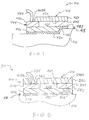
- FIG. 5 is an exploded view of a fourth embodiment of a fluid control valve assembly according to this invention.
- FIG. 6 is an enlarged sectional view of FIG. 5 taken along a line 6 — 6 of FIG. 5 .
- FIG. 7 is a sectional view of a fifth embodiment of a fluid control valve assembly according to this invention.
- FIG. 8 is a sectional view of a sixth embodiment of a fluid control valve assembly according to this invention.
- FIG. 9 is a flow chart illustrating a method of attaching a microvalve to a manifold according to the invention.
- a first embodiment of a fluid control valve assembly for controlling fluid flow in a high-pressure fluid circuit is shown generally at 10 in FIG. 1 .
- Examples of high-pressure fluid circuits in which the fluid control valve assembly 10 may be used include a vehicle brake circuit requiring pressures in excess of 200 bar, and a vehicle transmission system requiring fluid pressures exceeding 20 bar.
- the valve assembly 10 includes a microvalve device 12 of any suitable type. Examples of suitable microvalve devices include any one of the microvalve devices described in U.S. patent application Ser. No. 08/865,466, filed May 29, 1997, incorporated herein by reference, and U.S. patent application Ser. No. 09/148,024, filed Sep. 3, 1998, incorporated herein by reference.
- the microvalve device 12 has, like any valve, internal flow passages (not shown) for admitting and discharging fluid flow through the valve.
- the microvalve device 12 is attached to a fluid distributing substrate or manifold 14 to form a pair of high-pressure fluid connections between the microvalve device 12 and the fluid distributing substrate 14 .
- the microvalve may have a suitably metallized surface to allow a metallic bonding, such as solder, between the microvalve device 12 and the substrate 14 .
- the fluid distributing substrate 14 is shown as a flat, four-sided member.
- the fluid distributing substrate 14 may be any suitable shape.
- the fluid distributing substrate 14 may be any suitable material such as metals, ceramics, metal matrix composites, and the like. Examples of metallic materials believed to be especially suitable for some applications include iron-nickel alloys, carbon-nickel alloys, nickel-iron alloys, aluminum alloys and the like.
- the fluid distributing substrate 14 be made of material having a low rate of thermal expansion that remains generally constant throughout the working temperature range of the valve assembly 10 .
- An example of such a material is Carpenter Low Expansion “42”® (K94101) manufactured by Carpenter Steel Division of Carpenter Technology Corporation, Reading, Pennsylvania.
- Carpenter Low Expansion “42” is a nickel-iron alloy consisting of about 0.05% carbon, 0.4% manganese, 0.2% silicon, 41% nickel, and the remaining balance iron.
- Other materials believed to be suitable include KOVAR® (alloy containing about 54% iron, about 28% nickel and about 18% cobalt), aluminum nitride, and metal matrix composites such as Al/SiC or Cu/C (graphite).
- FIG. 2 shows the fluid distributing substrate 14 defining a pair of fluid passages 16 A and 16 B.
- the fluid distributing substrate 14 may be configured so as to define any number of fluid passages.
- the fluid distributing substrate 14 is adapted such that one end of each of the fluid passages 16 A, 16 B is connectable in fluid communication with a respective fluid source or medium (not shown).
- a respective fluid source or medium not shown.
- the fluid source may have a relatively high fluid pressure, such as the discharge pressure of a running pump, in which case fluid will tend to flow from that fluid source to the respective fluid passage 16 A, 16 B.
- the fluid source may have a relatively low fluid pressure, such as the suction pressure of a running pump, in which case the fluid will tend to flow from the respective fluid passage 16 A, 16 B to the fluid source.
- the valve assembly 10 further includes attachment structure, indicated generally at 18 in FIG. 2 .
- the attachment structure 18 attaches the microvalve device 12 to the fluid distributing substrate 14 such that each of the fluid passages 16 A, 16 B is sealably connected to a respective port (not shown) of the microvalve device 12 .
- the attachment structure 18 includes a primary solder joint 20 between and attached to the metallized suface(s) of the microvalve device 12 and the fluid distributing substrate 14 .
- the fluid passage 16 A is connected in fluid communication with one of the internal passages of the microvalve device 12 through an associated void 20 A in the solder joint 20 .
- the attachment structure 18 also includes secondary solder joints 21 between and attached to the fluid distributing substrate 14 and a predetermined portion or portions of the microvalve device 12 .
- the attachment structure 18 may further include an underfill 22 attached to the microvalve device 12 and the fluid distributing substrate 14 between the primary solder joint 20 and each of the secondary solder joints 21 .
- the material and application processes of the solder joints 20 , 21 and the underfill 22 are of suitable types.
- solder joints 20 , 21 examples include a solder alloy of 60% Tin and 40% Lead (60/40 Sn—Pb) or other alloys such s 25/75 Sn—Pb, and the like.
- suitable materials for the underfill 22 include epoxies, acrylates, cyanate esters, and the like. It should be understood that in certain applications the primary solder joint 20 and/or the secondary solder joints 21 may be replaced by additional underfill 22 . In other applications, the underfill 22 may be omitted entirely.
- one of the microvalve device 12 and the fluid distributing substrate 14 may be formed with a surface coated with a dielectric, such as silicon dioxide between the solder joints 20 , 21 and the other one of the microvalve device 12 and the fluid distributing substrate 14 .
- the microvalve device 12 selectively allows and restricts fluid flow between the fluid passages 16 A and 16 B, and thus between the respective fluid sources connected to the fluid passages 16 A and 16 B.
- the primary solder joint 20 holds the microvalve device 12 and the fluid distributing substrate 14 to each other while preventing fluid leakage from the fluid passages formed by the voids 20 A and 20 B.
- the secondary solder joints 21 assist in holding the microvalve device 12 and the fluid distributing substrate 14 to each other.
- the underfill 22 in addition to assisting the holding of the microvalve device 12 in place, may also improve the fatigue life of the solder joints 20 , 21 by relieving stress attributed to thermal expansion differentials between the microvalve device 12 , the solder joints 20 , 21 and the fluid distributing substrate 14 . Furthermore, the underfill 22 may prevent fluid from escaping the valve assembly 10 should the primary solder joint 20 fracture or otherwise lose structure integrity.
- a second embodiment of a fluid control valve assembly is shown generally at 110 in FIG. 3 .
- the valve assembly 110 is similar in structure and in function to the microvalve device 10 .
- Features of the valve assembly 110 corresponding to features of the microvalve device 10 are preceded by a “1”.
- the valve assembly includes a microvalve device 112 sealably connected in fluid communication with a fluid distributing substrate 114 by an attachment structure 118 .
- a first wirebond 124 A and a second wirebond 124 B electrically interconnect the microvalve device 112 and an electrical power supply (not shown).
- the wirebonds 124 A, 124 B provide electrical current supplied from the electrical power supply to the microvalve device 112 for actuating the microvalve device.
- the wirebonds 124 A, 124 B are directly connected to the electrical power supply to complete an electrical circuit.
- the wirebonds 124 A and 124 B may be electrically connected to separate conductive plates or films (not shown), which are supported by the fluid distributing substrate 114 .
- the fluid distributing substrate 114 is made of an electrically conductive material, the conductive plates or films are suitably electrically insulated from the fluid distributing substrate 114 .
- the attachment structure 118 includes an encapsulant 126 or glob top encasing each surface of the microvalve device 112 which would otherwise be left exposed having properly positioned the microvalve device 112 to the fluid distributing substrate 114 . Additionally, the encapsulant 126 may preferably be attached to a portion of the fluid distributing substrate 114 . Indeed, as shown in FIG. 3, the encapsulant 126 covers all the faces of the microvalve device 112 that are not soldered to the fluid distributing substrate 114 , and additionally portions of the fluid distributing substrate 114 around the region soldered to the microvalve device 112 . Thus, the encapsulant 126 and the fluid distributing substrate 114 cooperate to completely enclose the microvalve device 112 .
- the encapsulant 126 may be any suitable type including an epoxy, an acrylate, a cyanate ester, and the like.
- the encapsulant 126 assists in holding the microvalve device 112 in place by providing an adhesive force that reacts against fluid forces acting on the microvalve device 112 associated with the fluid in the fluid passages 116 A and 116 B. In certain application, it may be advantageous for the encapsulant 126 to apply a pre-load to the microvalve device 112 . This pre-loaded condition may be accomplished by using an encapsulant material having a coefficient of expansion that during a predetermined curing process generates a residual stress acting to exert force on the microvalve device 112 . The encapsulant 126 also acts as a secondary seal for preventing fluid from escaping the valve assembly 110 .
- the encapsulant 126 may also improve the fatigue life of the attachment structure 118 as a whole by exerting a force that minimizes stresses caused by thermal expansion differentials between the microvalve device 112 and the fluid distributing substrate 114 .
- the encapsulant 126 may improve the functioning of the microvalve device 112 by providing a thermal path for dissipating heat associated with the microvalve device 112 .
- the encapsulant 126 provides protection against physical and environmental damage to the valve assembly 110 and to the wirebonds 124 A, 124 B.
- a third embodiment of a fluid control valve assembly is shown generally at 210 in FIG. 4 .
- the valve assembly 210 is similar in structure and in function to the microvalve device 110 .
- Features of the valve assembly 210 corresponding to features of the microvalve device 110 are preceded by a “2” in place of a “1”.
- the valve assembly 210 includes a microvalve device 212 sealably connected in fluid communication with a fluid distributing substrate 214 by an attachment structure 218 .
- the attachment structure 218 includes an encapsulant 226 that encases the microvalve device 212 and is preferably attached to the fluid distributing substrate 214 . It should be understood that while it is preferable for the encapsulant 226 to attach to the fluid distributing substrate 214 , it may be suitable for the encapsulant 226 to simply contact the fluid distributing substrate 214 or to not even contact the fluid distributing substrate 214 .
- the attachment structure further includes a cap 228 contacting a portion of an otherwise exposed surface of the encapsulant 226 that is opposite the surface of the microvalve device 112 attached to the fluid distributing substrate 114 .
- the cap 228 is a flat, four-sided plate.
- the cap 228 may be of and suitable shape.
- the cap 228 has comers that preferably overhang beyond the periphery of the encapsulant 226 .
- Apertures are formed in the cap 228 adjacent each corner of the cap 228 .
- a bolt 230 or other suitable fastener extends through each aperture and is fastened to the fluid distributing substrate 214 .
- the bolt 230 has an enlarged head 234 that retains the cap 228 to the bolt 230 .
- the bolts 230 may be replaced by posts (not shown) secured in any suitable fashion, such as by welding, soldering, or by an adhesive, to the cap 228 and to the fluid distributing substrate 214 .
- the cap 228 assists in holding the microvalve device 212 in place by providing a clamping force acting on the encapsulant 226 that acts against fluid forces transmitted from the microvalve device 212 through the encapsulant 226 .
- the clamping force provided by the cap 228 can be varied for a given application by varying the torque or length of the bolts 230 , varying the length of the posts, or by varying the formation of the encapsulant 226 .
- the cap 228 also provides protection against physical damage to the encapsulant 226 and microvalve device 212 .
- the cap 228 may provide a thermal path for dissipating heat associated with the microvalve device 212 and the fluid distributing substrate 214 .
- FIG. 5 is an exploded view of a fourth embodiment of a fluid control valve assembly shown generally at 310 .
- the valve assembly 310 is similar in structure and in function to the microvalve device 10 .
- Features of the valve assembly 310 corresponding to features of the microvalve device 10 are preceded by a “3”.
- the valve assembly 310 includes a microvalve device 312 sealably connected in fluid communication with a fluid distributing substrate 314 by an attachment structure 318 .
- the fluid distributing substrate 314 defines a pair of fluid passages 316 A and 316 B extending through the fluid distributing substrate 314 between a first face 336 of the fluid distributing substrate 314 and a second face (not shown) opposite the first face 336 .
- the first face 336 defines a pocket 338 adjacent the fluid passages 316 A and 316 B.
- the pocket 338 may be of any suitable shape, but is shown having four sides: a first side 338 A adjacent the fluid passages 316 A and 316 B, a second side 338 B opposing the first side 338 A, a third side 338 C extending between the first side 338 A and the second side 338 B, and fourth 338 D opposing the third side 338 C.
- Resting pads 340 extend from the first face 336 adjacent the second side 338 B. Alternatively, any number of resting pads 340 may be located about any or all of the sides 338 A- 338 D, which will be made clearer in view of the purpose of the resting pads 340 discussed below.
- the attachment structure 318 includes a solder joint 320 between and attached to the microvalve device 312 and the fluid distributing substrate 314 .
- a pair of voids 320 A and 320 B are formed in the solder joint 320 .
- the void 320 A provides fluid communication between the passage 316 A and an associated fluid passage in the microvalve device 312 .
- the void 320 B provides fluid communication between the passage 316 B and an associated fluid passage in the microvalve device 312 .
- the thickness of the solder joint 320 is substantially equal to the height of the resting pads 340 .
- the attachment structure 318 further includes an adhesive 342 disposed in the pocket 338 that adheres to the fluid distributing substrate 314 and to the microvalve device 312 .
- Any suitable adhesive may be used.
- the adhesive 342 is an elastomeric adhesive.
- One adhesive believed to be suitable, in some applications, for use as the adhesive 342 is a silicone adhesive such as the Q3-6611 adhesive manufactured by Dow Corning.
- the pocket 338 facilitates the process of applying the adhesive 342 .
- the pocket 338 reduces the likelihood of the adhesive of spilling over in the region of the fluid passages 316 A and 316 B or elsewhere.
- the pocket 338 may suitably be eliminated in some applications.
- the pocket 338 may be formed in the substrate 314 and not have the adhesive 342 disposed therein. Indeed, regardless of whether or not the adhesive 342 is used between the microvalve device 312 and the substrate 314 , it may be advantageous to form a pocket in the substrate 312 or the microvalve device 312 in certain areas to prevent contact between a wall of the microvalve device 312 and the substrate 312 in an area of the microvalve device 312 that is succeptable to contact stresses.
- An example of an area which may be succeptable to contact stresses is the wall surrounding the actuator of certain types of microvalves, where contact stress induced by even careful bonding of a substrate to the microvalve device in the region of the actuator may adversely affect the operation of the actuator and thus the operation of the microvalve.
- the adhesive 342 assists in holding the microvalve device 312 in place.
- the elastomeric adhesive 342 may provide in some applications a seal for preventing fluid from escaping the valve assembly 310 in the event that the solder joint 320 fails to prevent fluid leakage.
- the adhesive 342 may also improve the fatigue life of the solder joint 320 by limiting stresses attributed to thermal expansion differentials between the microvalve device 312 and the fluid distributing substrate 314 .
- the adhesive 342 may provide a thermal path for dissipating heat associated with the microvalve device 312 .
- an elastomeric adhesive 342 may operate to effectively eliminate or at least reduce the residual stress acting on the microvalve device 312 that might otherwise be generated as a result of the curing process of a relatively inelastic bond formed between the microvalve device 312 and the fluid distributing substrate 314 .
- the avoidance or at least a relative reduction of the presence of residual stress acting on the microvalve device 312 could be instrumental with regards to ensuring the intended functioning of the valve assembly 310 .
- a sectional view of a fifth embodiment of a fluid control valve assembly is shown generally at 410 in FIG. 7 .
- the valve assembly 410 is similar in structure and in function to the microvalve device 10 .
- Features of the valve assembly 410 corresponding to features of the microvalve device 10 are preceded by a “4”.
- the valve assembly 410 includes a microvalve device 412 held in fluid communication with a fluid distributing substrate 414 by an attachment structure 418 .
- the fluid distributing substrate 414 is preferably made of an electrically conductive material and is adapted for connection to a suitable electrical power supply (not shown) for a purpose discussed below.
- the microvalve device 412 includes a body indicated generally at 444 .
- the body 444 includes a first plate 446 attached to a second plate 448 .
- a third plate 450 is attached to the second plate 448 so that the second plate 448 is sandwiched between the first plate 446 and the third plate 450 .
- the plates 446 , 448 and 450 may have any suitable shape and may be bonded together by any suitable method.
- each of the plates 446 , 448 and 450 is generally rectangular in plan view.
- the plates 446 , 448 , and 450 may be made of any suitable material such as silicon, ceramic, aluminum, or the like.
- each of the plates 446 , 448 and 450 is made of a semiconductor material such as silicon.
- the first plate 446 and the third plate 450 are made of undoped silicon, while, the second plate 448 is made of doped silicon.
- the second plate 448 has a first end 456 (to the left as viewed in FIG. 7) and a second end 458 (to the right as viewed in FIG. 7 ).
- the second plate 448 defines a cavity 452 extending through a central portion of the second plate 448 .
- a valve apparatus (not shown) is disposed in the cavity 452 .
- the valve apparatus may be any microelectromechanical member or subassembly suitable for controlling fluid flow upon being selectively electrically energized or de-energized.
- the electrically actuated valve apparatus is connected to selected portions of the walls of the cavity 452 formed by the second plate 448 .
- the body 444 may be formed from adjoining plates numbering more or less than three.
- the cavity 452 is defined by a cavity or recess formed in one or more of the adjoining plates in which the a valve apparatus is disposed.
- the first plate 446 is narrow than the second plate 448 and offset toward the first end 456 of the second plate 448 so that the second end 458 of the second plate 448 overhangs beyond the edge of the first plate 446 , as shown in FIG. 7 .
- the third plate 450 is narrower than the second plate 448 and offset toward the second end 458 of the second plate 448 to leave a surface 448 B of the second plate 448 not in contact with the third plate 450 .
- a wirebond 424 adapted for connection to the electrical power supply, is connected to the surface 448 B of the second plate 448 .
- the attachment structure 418 includes a solder joint 420 extending between and attached to the fluid distributing substrate 414 and the third plate 450 .
- the surfaces of the substrate 414 and the third plate 450 are preferably metallized by the deposition of a suitable metallic layer (not shown) thereon prior to soldering.
- the metallic layer may be deposited by any suitable process.
- the solder joint 420 also extends between and is attached to the fluid distributing substrate 414 and the surface 448 A of the second plate 448 . Not illustrated are fluid passages between the fluid distributing substrate 414 and the valve apparatus in the cavity 452 . These passages would be similar in nature to fluid passages in the fluid distributing substrates, attachment structure and microvalve devices illustrated in FIGS. 2-6.
- the solder joint 420 forms an electrical connection between the doped (electrically conductive) second plate 448 and the fluid distributing substrate 414 .
- the fluid distributing substrate 414 may also be connected to the electrical power supply. This completes an electrical circuit from the electrical power supply through the wirebond 424 to the doped second plate 448 at the surface 448 B, through one wall of the cavity 452 to the electrically actuated valve apparatus disposed in the cavity 452 .
- the return electrical path from the valve apparatus is through another wall of the cavity 452 , through the second plate 448 to the surface 448 A thereof, through the fluid distributing substrate 414 and back to the power supply.
- the electrical current is prevented from short-circuiting from the second plate 448 in the region of the surface 448 B to the solder joint 420 by the undoped (non-conductive) first plate 446 .
- the valve assembly 410 requires only one wirebond 424 connected to the microvalve device 412 to complete the electrical connection to the electrical power supply.
- the solder joint 420 serves the same purpose as a second wirebond.
- the package size of the microvalve device can be reduced, which may result in a less costly valve assembly 410 , and one which may be more flexible in placement within the space available for installation of the valve assembly 410 .
- first plate 446 and the third plate 450 are made from an electrically conductive material, it is preferable that a suitable dielectric, such as a silicon dioxide layer, be placed between the second plate 448 and each of the first and third plates 446 and 450 .
- a suitable dielectric such as a silicon dioxide layer
- FIG. 8 A sectional view of a sixth embodiment of a fluid control valve assembly shown generally 510 in FIG. 8 .
- the valve assembly 510 is similar in structure and in function to the microvalve device 410 .
- Features of the valve assembly 510 corresponding to features of the microvalve device 410 are preceded by a “5” in place of a “4”.
- the valve assembly 510 includes a microvalve device 512 sealably connected in fluid communication with a fluid distributing substrate 514 by an attachment structure 518 .
- the microvalve device 512 includes a body indicated generally at 544 .
- the body 544 includes a second plate 548 between and attached to a first plate 546 and a third plate 550 .
- the first plate 546 and the third plate 550 are made of undoped silicon, while, the second plate 548 is made of doped silicon.
- the second plate 548 has a first end 556 (to the left as viewed in FIG. 8) and a second end 558 (to the right as viewed in FIG. 8 ).
- the second plate 548 defines a cavity 552 extending through a central portion of the second plate 548 .
- a valve apparatus (not shown) is disposed in the cavity 552 .
- the valve apparatus of the microvalve 512 is similar in structure and in function to the valve apparatus of the microvalve device 412 .
- An aperture 560 is formed through the first plate 546 adjacent to the second end 558 of the second plate 548 .
- the aperture 560 exposes a surface 548 A on the second plate 548 .
- an aperture 562 formed through the third plate 550 adjacent to the first end 556 of the second plate 548 exposes a surface 548 B on the second plate 548 .
- a wirebond 524 adapted for connection to an electrical power supply, is connected to the surface 548 B of the second plate 548 by any suitable method, such as welding, soldering, or the like.
- the attachment structure includes a solder joint 520 .
- the solder joint 520 extends into the aperture 560 and bonds with the surface 548 A.
- the solder joint 520 also extends between and bonds with portions of the first plate 546 and the fluid distributing substrate 514 .
- the solder joint 520 provides a mechanical connection and an electrical connection between the microvalve device 512 and the fluid distributing substrate 514 .
- valve assembly 510 In operation, electrical current flows through the valve assembly 510 similar to the electrical current flow through the valve assembly 410 .
- FIG. 9 A general method for attaching a microvalve device to a manifold is illustrated in FIG. 9 .
- a manifold is provided which defines a surface to be attached to the microvalve device.
- the manifold has a fluid passage formed therethrough from an opening defined in the surface.
- at least a portion of the surface of the manifold is metallized through any conventional method, such as plating with copper.
- a photo resist may be laminated to the manifold to mask off areas of the manifold which are not to be metallized, followed by plating of the unmasked portions of the surface of the manifold.
- the photo resist could then be removed by conventional methods.
- the manifold is preferably metallized in a desired pattern, with the metallization extending on the surface of the manifold about the opening in the surface.
- a microvalve device to be attached to the manifold is provided.
- the microvalve device defines a surface and has an opening defined in the surface thereof.
- a fluid passage is formed through the microvalve device from the opening in the surface of the microvalve device.
- at least a portion of the surface of the microvalve device is metallized in any suitable manner, such as the method described above with respect to the manifold, to form a desired pattern on the microvalve device surface.
- the surface of the microvalve device is metallized around, but not in, the opening in the surface thereof, and is not metallized adjacent to the actuator portion of the microvalve device.
- solder is deposited in the desired pattern on the surface of the manifold, with the solder extending about the opening but, preferably, not onto the non-metallized surfaces of the manifold.
- the solder may be deposited in various ways, including placement of a solder preform, screen printing with a solder paste plating operation, or other suitable fashion.
- the microvalve device is placed with the surface thereof mating with the surface of the manifold so that the fluid passages of the microvalve device and the manifold are in mutual communication, with the solder contacting the metallized portions of the surface of the microvalve device about the opening in the surface of the microvalve device.
- the solder is reflowed between the microvalve device and the manifold to form a solder joint joining the microvalve device and the manifold.
- the solder may be reflowed by any suitable method, such as by heating the microvalve device and the manifold in a reflow oven and subsequently cooling the microvalve device and the manifold.
- the solder of the solder joint forms a part of a high-pressure fluid circuit between the microvalve device and the manifold.
- underfill may be dispensed in selected areas between the microvalve device and the manifold.
- the underfill may, for example, be an epoxy adhesive or other suitable adhesive.
- the order of the steps of this method may be suitably rearranged.
- the microvalve device might be metallized prior to the manifold being metallized, or the solder applied to the surface of the manifold prior to the provision of the microvalve. It is also contemplated that the solder may be placed on the surface of the microvalve device initially, rather than on the manifold surface.
Abstract
Description
Claims (18)
Priority Applications (1)
| Application Number | Priority Date | Filing Date | Title |
|---|---|---|---|
| US09/604,591 US6505811B1 (en) | 2000-06-27 | 2000-06-27 | High-pressure fluid control valve assembly having a microvalve device attached to fluid distributing substrate |
Applications Claiming Priority (1)
| Application Number | Priority Date | Filing Date | Title |
|---|---|---|---|
| US09/604,591 US6505811B1 (en) | 2000-06-27 | 2000-06-27 | High-pressure fluid control valve assembly having a microvalve device attached to fluid distributing substrate |
Publications (1)
| Publication Number | Publication Date |
|---|---|
| US6505811B1 true US6505811B1 (en) | 2003-01-14 |
Family
ID=24420240
Family Applications (1)
| Application Number | Title | Priority Date | Filing Date |
|---|---|---|---|
| US09/604,591 Expired - Lifetime US6505811B1 (en) | 2000-06-27 | 2000-06-27 | High-pressure fluid control valve assembly having a microvalve device attached to fluid distributing substrate |
Country Status (1)
| Country | Link |
|---|---|
| US (1) | US6505811B1 (en) |
Cited By (35)
| Publication number | Priority date | Publication date | Assignee | Title |
|---|---|---|---|---|
| US20060017030A1 (en) * | 2004-07-22 | 2006-01-26 | Harris Corporation | Embedded control valve using electroactive material |
| US20060022160A1 (en) * | 2004-07-27 | 2006-02-02 | Fuller Edward N | Method of controlling microvalve actuator |
| US20060027777A1 (en) * | 2004-08-03 | 2006-02-09 | Harris Corporation | Embedded control valve using homopolar motor |
| US7011288B1 (en) * | 2001-12-05 | 2006-03-14 | Microstar Technologies Llc | Microelectromechanical device with perpendicular motion |
| US20060243331A1 (en) * | 2003-11-24 | 2006-11-02 | Fuller Edward N | Microvalve device suitable for controlling a variable displacement compressor |
| US20070228499A1 (en) * | 2006-03-31 | 2007-10-04 | S3C, Inc. | MEMS device package with thermally compliant insert |
| US20070251586A1 (en) * | 2003-11-24 | 2007-11-01 | Fuller Edward N | Electro-pneumatic control valve with microvalve pilot |
| US20070289941A1 (en) * | 2004-03-05 | 2007-12-20 | Davies Brady R | Selective Bonding for Forming a Microvalve |
| US20080042084A1 (en) * | 2004-02-27 | 2008-02-21 | Edward Nelson Fuller | Hybrid Micro/Macro Plate Valve |
| US20080047622A1 (en) * | 2003-11-24 | 2008-02-28 | Fuller Edward N | Thermally actuated microvalve with multiple fluid ports |
| US7438030B1 (en) | 2005-08-26 | 2008-10-21 | The United States Of America As Represented By The Administrator Of The National Aeronautics And Space Administration | Actuator operated microvalves |
| US20080277747A1 (en) * | 2007-05-08 | 2008-11-13 | Nazir Ahmad | MEMS device support structure for sensor packaging |
| US20090102041A1 (en) * | 2007-10-17 | 2009-04-23 | Ted Ju | Electrical connection device and assembly method thereof |
| US20090123300A1 (en) * | 2005-01-14 | 2009-05-14 | Alumina Micro Llc | System and method for controlling a variable displacement compressor |
| US20090140194A1 (en) * | 2007-11-21 | 2009-06-04 | Takuya Kato | Valve device and multi-layer substrate |
| US20100044809A1 (en) * | 2008-08-21 | 2010-02-25 | S3C, Inc. | Sensor Device Packaging And Method |
| US20100304518A1 (en) * | 2009-03-03 | 2010-12-02 | S3C, Inc. | Media-Compatible Electrically Isolated Pressure Sensor For High Temperature Applications |
| US20110127455A1 (en) * | 2008-08-09 | 2011-06-02 | Microstaq, Inc. | Improved Microvalve Device |
| US8113482B2 (en) | 2008-08-12 | 2012-02-14 | DunAn Microstaq | Microvalve device with improved fluid routing |
| US20120043485A1 (en) * | 2009-04-24 | 2012-02-23 | Michael Foerg | Piezoelectric drive and microvalve comprising said drive |
| US8156962B2 (en) | 2006-12-15 | 2012-04-17 | Dunan Microstaq, Inc. | Microvalve device |
| US8387659B2 (en) | 2007-03-31 | 2013-03-05 | Dunan Microstaq, Inc. | Pilot operated spool valve |
| US8393344B2 (en) | 2007-03-30 | 2013-03-12 | Dunan Microstaq, Inc. | Microvalve device with pilot operated spool valve and pilot microvalve |
| US8540207B2 (en) | 2008-12-06 | 2013-09-24 | Dunan Microstaq, Inc. | Fluid flow control assembly |
| US8593811B2 (en) | 2009-04-05 | 2013-11-26 | Dunan Microstaq, Inc. | Method and structure for optimizing heat exchanger performance |
| US8925793B2 (en) | 2012-01-05 | 2015-01-06 | Dunan Microstaq, Inc. | Method for making a solder joint |
| CN104329484A (en) * | 2013-06-24 | 2015-02-04 | 浙江盾安禾田金属有限公司 | Microvalve Having Improved Resistance to Contamination |
| US8956884B2 (en) | 2010-01-28 | 2015-02-17 | Dunan Microstaq, Inc. | Process for reconditioning semiconductor surface to facilitate bonding |
| US8996141B1 (en) | 2010-08-26 | 2015-03-31 | Dunan Microstaq, Inc. | Adaptive predictive functional controller |
| US9006844B2 (en) | 2010-01-28 | 2015-04-14 | Dunan Microstaq, Inc. | Process and structure for high temperature selective fusion bonding |
| US9140613B2 (en) | 2012-03-16 | 2015-09-22 | Zhejiang Dunan Hetian Metal Co., Ltd. | Superheat sensor |
| US9188375B2 (en) | 2013-12-04 | 2015-11-17 | Zhejiang Dunan Hetian Metal Co., Ltd. | Control element and check valve assembly |
| US9702481B2 (en) | 2009-08-17 | 2017-07-11 | Dunan Microstaq, Inc. | Pilot-operated spool valve |
| US9970535B1 (en) | 2014-10-13 | 2018-05-15 | Dunan Microstaq, Inc. | Linear package for a two-stage control microvalve |
| US10211127B1 (en) * | 2016-03-28 | 2019-02-19 | Lockheed Martin Corporation | Integration of chip level micro-fluidic cooling in chip packages for heat flux removal |
Citations (56)
| Publication number | Priority date | Publication date | Assignee | Title |
|---|---|---|---|---|
| US3031747A (en) | 1957-12-31 | 1962-05-01 | Tung Sol Electric Inc | Method of forming ohmic contact to silicon |
| US3729807A (en) | 1970-10-30 | 1973-05-01 | Matsushita Electronics Corp | Method of making thermo-compression-bonded semiconductor device |
| DE2215526A1 (en) | 1972-03-30 | 1973-10-04 | Licentia Gmbh | Metal contact for semiconductors - with consecutive chromium, chromium/nickel, nickel and gold layers, is junction-free |
| US3860949A (en) | 1973-09-12 | 1975-01-14 | Rca Corp | Semiconductor mounting devices made by soldering flat surfaces to each other |
| US4005454A (en) | 1975-04-05 | 1977-01-25 | Semikron Gesellschaft Fur Gleichrichterbau Und Elektronik M.B.H. | Semiconductor device having a solderable contacting coating on its opposite surfaces |
| US4019388A (en) | 1976-03-11 | 1977-04-26 | Bailey Meter Company | Glass to metal seal |
| US4023725A (en) | 1974-03-04 | 1977-05-17 | U.S. Philips Corporation | Semiconductor device manufacture |
| US4152540A (en) | 1977-05-03 | 1979-05-01 | American Pacemaker Corporation | Feedthrough connector for implantable cardiac pacer |
| US4181249A (en) | 1977-08-26 | 1980-01-01 | Hughes Aircraft Company | Eutectic die attachment method for integrated circuits |
| DE2930779A1 (en) | 1978-07-28 | 1980-02-07 | Tokyo Shibaura Electric Co | Contact layer for semiconductor chip - consists of three or four metal layers giving firm bond and including gold-germanium alloy layer for soldering |
| US4341816A (en) | 1979-08-21 | 1982-07-27 | Siemens Aktiengesellschaft | Method for attaching disc- or plate-shaped targets to cooling plates for sputtering systems |
| US4434813A (en) | 1981-11-19 | 1984-03-06 | The United States Of America As Represented By The Secretary Of The Army | Laminar proportional amplifier and laminar jet angular rate sensor with rotating splitter for null adjustment |
| DE3401404A1 (en) | 1984-01-17 | 1985-07-25 | Robert Bosch Gmbh, 7000 Stuttgart | SEMICONDUCTOR COMPONENT |
| US4581624A (en) | 1984-03-01 | 1986-04-08 | Allied Corporation | Microminiature semiconductor valve |
| US4647013A (en) * | 1985-02-21 | 1987-03-03 | Ford Motor Company | Silicon valve |
| US4772935A (en) | 1984-12-19 | 1988-09-20 | Fairchild Semiconductor Corporation | Die bonding process |
| US4821997A (en) | 1986-09-24 | 1989-04-18 | The Board Of Trustees Of The Leland Stanford Junior University | Integrated, microminiature electric-to-fluidic valve and pressure/flow regulator |
| US4824073A (en) | 1986-09-24 | 1989-04-25 | Stanford University | Integrated, microminiature electric to fluidic valve |
| US4869282A (en) * | 1988-12-09 | 1989-09-26 | Rosemount Inc. | Micromachined valve with polyimide film diaphragm |
| US4891120A (en) * | 1986-06-06 | 1990-01-02 | Sethi Rajinder S | Chromatographic separation device |
| US4943032A (en) | 1986-09-24 | 1990-07-24 | Stanford University | Integrated, microminiature electric to fluidic valve and pressure/flow regulator |
| US4959581A (en) | 1987-11-13 | 1990-09-25 | Mannesmann Rexroth Gmbh | Servo valve having a piezoelectric element as a control motor |
| US4966646A (en) | 1986-09-24 | 1990-10-30 | Board Of Trustees Of Leland Stanford University | Method of making an integrated, microminiature electric-to-fluidic valve |
| GB2238267A (en) | 1989-11-01 | 1991-05-29 | Stc Plc | Brazing process |
| US5029805A (en) | 1988-04-27 | 1991-07-09 | Dragerwerk Aktiengesellschaft | Valve arrangement of microstructured components |
| US5037778A (en) | 1989-05-12 | 1991-08-06 | Intel Corporation | Die attach using gold ribbon with gold/silicon eutectic alloy cladding |
| US5054522A (en) | 1989-05-29 | 1991-10-08 | Burkert Gmbh Werk Ingelfingen | Microvalve |
| US5074629A (en) | 1988-10-26 | 1991-12-24 | Stanford University | Integrated variable focal length lens and its applications |
| US5096643A (en) | 1989-05-29 | 1992-03-17 | Burkert Gmbh Werk Ingelfingen | Method of manufacturing microvalves |
| US5131729A (en) | 1989-12-07 | 1992-07-21 | Robert Bosch Gmbh | Vehicle brake system with anti-skid apparatus |
| US5133379A (en) | 1990-01-31 | 1992-07-28 | University Of Utah Research Foundation | Servovalve apparatus for use in fluid systems |
| US5142781A (en) | 1989-08-11 | 1992-09-01 | Robert Bosch Gmbh | Method of making a microvalve |
| US5161774A (en) | 1989-06-19 | 1992-11-10 | Robert Bosch Gmbh | Microvalve |
| US5178190A (en) | 1990-12-22 | 1993-01-12 | Robert Bosch Gmbh | Microvalve |
| US5215244A (en) | 1991-03-09 | 1993-06-01 | Robert Bosch Gmbh | Method of mounting silicon wafers on metallic mounting surfaces |
| US5216273A (en) | 1990-11-10 | 1993-06-01 | Robert Bosch Gmbh | Microvalve of multilayer silicon construction |
| US5217283A (en) | 1991-09-25 | 1993-06-08 | Ford Motor Company | Integral anti-lock brake/traction control system |
| US5238223A (en) | 1989-08-11 | 1993-08-24 | Robert Bosch Gmbh | Method of making a microvalve |
| US5267589A (en) | 1993-04-05 | 1993-12-07 | Ford Motor Company | Piezoelectric pressure control valve |
| US5271431A (en) | 1990-02-07 | 1993-12-21 | Robert Bosch Gmbh | Microvalve |
| US5309943A (en) | 1992-12-07 | 1994-05-10 | Ford Motor Company | Micro-valve and method of manufacturing |
| US5375919A (en) | 1992-08-07 | 1994-12-27 | Nisshinbo Industries Inc. | Anti-skid control method |
| US5400824A (en) | 1991-01-21 | 1995-03-28 | Robert Bosch Gmbh | Microvalve |
| US5445185A (en) | 1993-04-05 | 1995-08-29 | Ford Motor Company | Piezoelectric fluid control valve |
| US5454906A (en) * | 1994-06-21 | 1995-10-03 | Texas Instruments Inc. | Method of providing sacrificial spacer for micro-mechanical devices |
| US5458405A (en) | 1993-03-31 | 1995-10-17 | Toyota Jidosha Kabushiki Kaisha | Motor vehicle brake pressure control apparatus wherein brake pressure is controlled based on estimated future wheel speed |
| US5460908A (en) * | 1991-08-02 | 1995-10-24 | Micron Technology, Inc. | Phase shifting retical fabrication method |
| US5553790A (en) | 1993-09-20 | 1996-09-10 | Robert Bosch Gmbh | Orifice element and valve with orifice element |
| US5909078A (en) | 1996-12-16 | 1999-06-01 | Mcnc | Thermal arched beam microelectromechanical actuators |
| US5926955A (en) | 1995-07-22 | 1999-07-27 | Robert Bosch Gmbh | Microvalve with joined layers of metal parts and process for manufacture of a microvalve |
| US5941608A (en) | 1996-03-07 | 1999-08-24 | Kelsey-Hayes Company | Electronic brake management system with manual fail safe |
| US6019437A (en) | 1996-05-29 | 2000-02-01 | Kelsey-Hayes Company | Vehicle hydraulic braking systems incorporating micro-machined technology |
| US6116863A (en) * | 1997-05-30 | 2000-09-12 | University Of Cincinnati | Electromagnetically driven microactuated device and method of making the same |
| US6168395B1 (en) * | 1996-02-10 | 2001-01-02 | Fraunhofer-Gesellschaft Zur Foerderung Der Angewandten Forschung E.V. | Bistable microactuator with coupled membranes |
| US6184065B1 (en) * | 1995-06-07 | 2001-02-06 | Xerox Corporation | Photolithographically patterned spring contact |
| US6213789B1 (en) * | 1999-12-15 | 2001-04-10 | Xerox Corporation | Method and apparatus for interconnecting devices using an adhesive |
-
2000
- 2000-06-27 US US09/604,591 patent/US6505811B1/en not_active Expired - Lifetime
Patent Citations (58)
| Publication number | Priority date | Publication date | Assignee | Title |
|---|---|---|---|---|
| US3031747A (en) | 1957-12-31 | 1962-05-01 | Tung Sol Electric Inc | Method of forming ohmic contact to silicon |
| US3729807A (en) | 1970-10-30 | 1973-05-01 | Matsushita Electronics Corp | Method of making thermo-compression-bonded semiconductor device |
| DE2215526A1 (en) | 1972-03-30 | 1973-10-04 | Licentia Gmbh | Metal contact for semiconductors - with consecutive chromium, chromium/nickel, nickel and gold layers, is junction-free |
| US3860949A (en) | 1973-09-12 | 1975-01-14 | Rca Corp | Semiconductor mounting devices made by soldering flat surfaces to each other |
| US4023725A (en) | 1974-03-04 | 1977-05-17 | U.S. Philips Corporation | Semiconductor device manufacture |
| US4005454A (en) | 1975-04-05 | 1977-01-25 | Semikron Gesellschaft Fur Gleichrichterbau Und Elektronik M.B.H. | Semiconductor device having a solderable contacting coating on its opposite surfaces |
| US4019388A (en) | 1976-03-11 | 1977-04-26 | Bailey Meter Company | Glass to metal seal |
| US4152540A (en) | 1977-05-03 | 1979-05-01 | American Pacemaker Corporation | Feedthrough connector for implantable cardiac pacer |
| US4181249A (en) | 1977-08-26 | 1980-01-01 | Hughes Aircraft Company | Eutectic die attachment method for integrated circuits |
| DE2930779A1 (en) | 1978-07-28 | 1980-02-07 | Tokyo Shibaura Electric Co | Contact layer for semiconductor chip - consists of three or four metal layers giving firm bond and including gold-germanium alloy layer for soldering |
| US4341816A (en) | 1979-08-21 | 1982-07-27 | Siemens Aktiengesellschaft | Method for attaching disc- or plate-shaped targets to cooling plates for sputtering systems |
| US4434813A (en) | 1981-11-19 | 1984-03-06 | The United States Of America As Represented By The Secretary Of The Army | Laminar proportional amplifier and laminar jet angular rate sensor with rotating splitter for null adjustment |
| DE3401404A1 (en) | 1984-01-17 | 1985-07-25 | Robert Bosch Gmbh, 7000 Stuttgart | SEMICONDUCTOR COMPONENT |
| US4661835A (en) | 1984-01-17 | 1987-04-28 | Robert Bosch Gmbh | Semiconductor structure and method of its manufacture |
| US4581624A (en) | 1984-03-01 | 1986-04-08 | Allied Corporation | Microminiature semiconductor valve |
| US4772935A (en) | 1984-12-19 | 1988-09-20 | Fairchild Semiconductor Corporation | Die bonding process |
| US4647013A (en) * | 1985-02-21 | 1987-03-03 | Ford Motor Company | Silicon valve |
| US4891120A (en) * | 1986-06-06 | 1990-01-02 | Sethi Rajinder S | Chromatographic separation device |
| US4821997A (en) | 1986-09-24 | 1989-04-18 | The Board Of Trustees Of The Leland Stanford Junior University | Integrated, microminiature electric-to-fluidic valve and pressure/flow regulator |
| US4824073A (en) | 1986-09-24 | 1989-04-25 | Stanford University | Integrated, microminiature electric to fluidic valve |
| US4966646A (en) | 1986-09-24 | 1990-10-30 | Board Of Trustees Of Leland Stanford University | Method of making an integrated, microminiature electric-to-fluidic valve |
| US4943032A (en) | 1986-09-24 | 1990-07-24 | Stanford University | Integrated, microminiature electric to fluidic valve and pressure/flow regulator |
| US4959581A (en) | 1987-11-13 | 1990-09-25 | Mannesmann Rexroth Gmbh | Servo valve having a piezoelectric element as a control motor |
| US5029805A (en) | 1988-04-27 | 1991-07-09 | Dragerwerk Aktiengesellschaft | Valve arrangement of microstructured components |
| US5074629A (en) | 1988-10-26 | 1991-12-24 | Stanford University | Integrated variable focal length lens and its applications |
| US4869282A (en) * | 1988-12-09 | 1989-09-26 | Rosemount Inc. | Micromachined valve with polyimide film diaphragm |
| US5037778A (en) | 1989-05-12 | 1991-08-06 | Intel Corporation | Die attach using gold ribbon with gold/silicon eutectic alloy cladding |
| US5054522A (en) | 1989-05-29 | 1991-10-08 | Burkert Gmbh Werk Ingelfingen | Microvalve |
| US5096643A (en) | 1989-05-29 | 1992-03-17 | Burkert Gmbh Werk Ingelfingen | Method of manufacturing microvalves |
| US5161774A (en) | 1989-06-19 | 1992-11-10 | Robert Bosch Gmbh | Microvalve |
| US5238223A (en) | 1989-08-11 | 1993-08-24 | Robert Bosch Gmbh | Method of making a microvalve |
| US5142781A (en) | 1989-08-11 | 1992-09-01 | Robert Bosch Gmbh | Method of making a microvalve |
| GB2238267A (en) | 1989-11-01 | 1991-05-29 | Stc Plc | Brazing process |
| US5131729A (en) | 1989-12-07 | 1992-07-21 | Robert Bosch Gmbh | Vehicle brake system with anti-skid apparatus |
| US5133379A (en) | 1990-01-31 | 1992-07-28 | University Of Utah Research Foundation | Servovalve apparatus for use in fluid systems |
| US5271431A (en) | 1990-02-07 | 1993-12-21 | Robert Bosch Gmbh | Microvalve |
| US5216273A (en) | 1990-11-10 | 1993-06-01 | Robert Bosch Gmbh | Microvalve of multilayer silicon construction |
| US5178190A (en) | 1990-12-22 | 1993-01-12 | Robert Bosch Gmbh | Microvalve |
| US5400824A (en) | 1991-01-21 | 1995-03-28 | Robert Bosch Gmbh | Microvalve |
| US5215244A (en) | 1991-03-09 | 1993-06-01 | Robert Bosch Gmbh | Method of mounting silicon wafers on metallic mounting surfaces |
| US5460908A (en) * | 1991-08-02 | 1995-10-24 | Micron Technology, Inc. | Phase shifting retical fabrication method |
| US5217283A (en) | 1991-09-25 | 1993-06-08 | Ford Motor Company | Integral anti-lock brake/traction control system |
| US5375919A (en) | 1992-08-07 | 1994-12-27 | Nisshinbo Industries Inc. | Anti-skid control method |
| US5309943A (en) | 1992-12-07 | 1994-05-10 | Ford Motor Company | Micro-valve and method of manufacturing |
| US5458405A (en) | 1993-03-31 | 1995-10-17 | Toyota Jidosha Kabushiki Kaisha | Motor vehicle brake pressure control apparatus wherein brake pressure is controlled based on estimated future wheel speed |
| US5566703A (en) | 1993-04-05 | 1996-10-22 | Ford Motor Company | Fluid control valve |
| US5267589A (en) | 1993-04-05 | 1993-12-07 | Ford Motor Company | Piezoelectric pressure control valve |
| US5445185A (en) | 1993-04-05 | 1995-08-29 | Ford Motor Company | Piezoelectric fluid control valve |
| US5553790A (en) | 1993-09-20 | 1996-09-10 | Robert Bosch Gmbh | Orifice element and valve with orifice element |
| US5454906A (en) * | 1994-06-21 | 1995-10-03 | Texas Instruments Inc. | Method of providing sacrificial spacer for micro-mechanical devices |
| US6184065B1 (en) * | 1995-06-07 | 2001-02-06 | Xerox Corporation | Photolithographically patterned spring contact |
| US5926955A (en) | 1995-07-22 | 1999-07-27 | Robert Bosch Gmbh | Microvalve with joined layers of metal parts and process for manufacture of a microvalve |
| US6168395B1 (en) * | 1996-02-10 | 2001-01-02 | Fraunhofer-Gesellschaft Zur Foerderung Der Angewandten Forschung E.V. | Bistable microactuator with coupled membranes |
| US5941608A (en) | 1996-03-07 | 1999-08-24 | Kelsey-Hayes Company | Electronic brake management system with manual fail safe |
| US6019437A (en) | 1996-05-29 | 2000-02-01 | Kelsey-Hayes Company | Vehicle hydraulic braking systems incorporating micro-machined technology |
| US5909078A (en) | 1996-12-16 | 1999-06-01 | Mcnc | Thermal arched beam microelectromechanical actuators |
| US6116863A (en) * | 1997-05-30 | 2000-09-12 | University Of Cincinnati | Electromagnetically driven microactuated device and method of making the same |
| US6213789B1 (en) * | 1999-12-15 | 2001-04-10 | Xerox Corporation | Method and apparatus for interconnecting devices using an adhesive |
Non-Patent Citations (8)
| Title |
|---|
| "A Silicon Microvalve For The Proportional Control Of Fluids" by K.R. Williams, N.I. Maluf, E.N. Fuller, R.J. Barron, D.P. Jaeggi, and B.P. van Drieënhuizen, Transducers '99, Proc. 10th International Conference on Solid State Sensors and Actuators, held Jun. 7-10, 1999, Sendai, Japan, pp. 18-21. |
| Carpenter Technology Corporation Technical Data sheet for "Carpenter Low Expansion "42'", dated Nov. 1980. |
| Carpenter Technology Corporation Technical Data sheet for "Carpenter Low Expansion ‘42’", dated Nov. 1980. |
| IEEE Technical Digest entitled "Compliant Electro-thermal Microactuators", J. Jonsmann, O. Sigmund, S. Bouwstra, Twelfth IEEE International Conference on Micro Electro Mechanical Systems held Jan. 17-21, 1999, Orlando, Florida, pp. 588-593, IEEE Catalog No.: 99CH36291C. |
| Jing, Qi, R. Wayne Johnson, Erin Yaeger, Mark Konarski, and Larry Crane, "Flip Chip on Laminate Manufacturability," Proc. SPEI-Int. Soc. Opt. Eng. (USA) 1999 International Conference on High Density Packaging and MCMs. Held Apr. 6-9, 1999, Denver, CO, pp. 345-352. Copyright 2000, IEE. |
| Jing, Qi, R. Wayne Johnson, Erin Yaeger, Mark Konarski, and Larry Crane, "Flip Chip on Laminate Manufacturability," Proc. SPEI—Int. Soc. Opt. Eng. (USA) 1999 International Conference on High Density Packaging and MCMs. Held Apr. 6-9, 1999, Denver, CO, pp. 345-352. Copyright 2000, IEE. |
| Mark M. Konarski, "Cure Parameter Effects On The Tg and CTE Of Flip Encapsulants," 43rd International SAMPE Symposium and Exhibition. Materials and Process Affordability. Keys to the Future. Held May 31 to Jun. 4, 1998, Anaheim, CA, pp. 823-832 vol. 1. Copyright 1999, IEE. |
| Paul N. Houston, Daniel F. Baldwin, Marnico Deladisma, Lawrence N. Crane, and Mark Konarski, Low Cost Flip Chip Processing and Reliability of Fast-Flow, Snap-Cure Underfills, 1999 Proceedings. 49th Electronic Components and Technology Conference. Held Jun. 1-4, 1999, San Diego, CA, pp. 61-70. Copyright 2000, IEE. |
Cited By (50)
| Publication number | Priority date | Publication date | Assignee | Title |
|---|---|---|---|---|
| US7011288B1 (en) * | 2001-12-05 | 2006-03-14 | Microstar Technologies Llc | Microelectromechanical device with perpendicular motion |
| US20070251586A1 (en) * | 2003-11-24 | 2007-11-01 | Fuller Edward N | Electro-pneumatic control valve with microvalve pilot |
| US20060243331A1 (en) * | 2003-11-24 | 2006-11-02 | Fuller Edward N | Microvalve device suitable for controlling a variable displacement compressor |
| US8011388B2 (en) | 2003-11-24 | 2011-09-06 | Microstaq, INC | Thermally actuated microvalve with multiple fluid ports |
| US20080047622A1 (en) * | 2003-11-24 | 2008-02-28 | Fuller Edward N | Thermally actuated microvalve with multiple fluid ports |
| US20070172362A1 (en) * | 2003-11-24 | 2007-07-26 | Fuller Edward N | Microvalve device suitable for controlling a variable displacement compressor |
| US7210502B2 (en) | 2003-11-24 | 2007-05-01 | Microstaq Inc. | Microvalve device suitable for controlling a variable displacement compressor |
| US20080042084A1 (en) * | 2004-02-27 | 2008-02-21 | Edward Nelson Fuller | Hybrid Micro/Macro Plate Valve |
| US20070289941A1 (en) * | 2004-03-05 | 2007-12-20 | Davies Brady R | Selective Bonding for Forming a Microvalve |
| US7803281B2 (en) | 2004-03-05 | 2010-09-28 | Microstaq, Inc. | Selective bonding for forming a microvalve |
| US20060017030A1 (en) * | 2004-07-22 | 2006-01-26 | Harris Corporation | Embedded control valve using electroactive material |
| US7168680B2 (en) | 2004-07-22 | 2007-01-30 | Harris Corporation | Embedded control valve using electroactive material |
| US20060022160A1 (en) * | 2004-07-27 | 2006-02-02 | Fuller Edward N | Method of controlling microvalve actuator |
| US7093818B2 (en) | 2004-08-03 | 2006-08-22 | Harris Corporation | Embedded control valve using homopolar motor |
| US20060027777A1 (en) * | 2004-08-03 | 2006-02-09 | Harris Corporation | Embedded control valve using homopolar motor |
| US20090123300A1 (en) * | 2005-01-14 | 2009-05-14 | Alumina Micro Llc | System and method for controlling a variable displacement compressor |
| US7438030B1 (en) | 2005-08-26 | 2008-10-21 | The United States Of America As Represented By The Administrator Of The National Aeronautics And Space Administration | Actuator operated microvalves |
| US20070228499A1 (en) * | 2006-03-31 | 2007-10-04 | S3C, Inc. | MEMS device package with thermally compliant insert |
| US8156962B2 (en) | 2006-12-15 | 2012-04-17 | Dunan Microstaq, Inc. | Microvalve device |
| US8393344B2 (en) | 2007-03-30 | 2013-03-12 | Dunan Microstaq, Inc. | Microvalve device with pilot operated spool valve and pilot microvalve |
| US8387659B2 (en) | 2007-03-31 | 2013-03-05 | Dunan Microstaq, Inc. | Pilot operated spool valve |
| US20080277747A1 (en) * | 2007-05-08 | 2008-11-13 | Nazir Ahmad | MEMS device support structure for sensor packaging |
| US8039944B2 (en) * | 2007-10-17 | 2011-10-18 | Lotes Co., Ltd. | Electrical connection device and assembly method thereof |
| US20090102041A1 (en) * | 2007-10-17 | 2009-04-23 | Ted Ju | Electrical connection device and assembly method thereof |
| US20090140194A1 (en) * | 2007-11-21 | 2009-06-04 | Takuya Kato | Valve device and multi-layer substrate |
| US8662468B2 (en) | 2008-08-09 | 2014-03-04 | Dunan Microstaq, Inc. | Microvalve device |
| US20110127455A1 (en) * | 2008-08-09 | 2011-06-02 | Microstaq, Inc. | Improved Microvalve Device |
| US8113482B2 (en) | 2008-08-12 | 2012-02-14 | DunAn Microstaq | Microvalve device with improved fluid routing |
| US8643127B2 (en) | 2008-08-21 | 2014-02-04 | S3C, Inc. | Sensor device packaging |
| US20100044809A1 (en) * | 2008-08-21 | 2010-02-25 | S3C, Inc. | Sensor Device Packaging And Method |
| US8540207B2 (en) | 2008-12-06 | 2013-09-24 | Dunan Microstaq, Inc. | Fluid flow control assembly |
| US8316533B2 (en) | 2009-03-03 | 2012-11-27 | S3C, Inc. | Media-compatible electrically isolated pressure sensor for high temperature applications |
| US20100304518A1 (en) * | 2009-03-03 | 2010-12-02 | S3C, Inc. | Media-Compatible Electrically Isolated Pressure Sensor For High Temperature Applications |
| US8627559B2 (en) | 2009-03-03 | 2014-01-14 | S3C, Inc. | Media-compatible electrically isolated pressure sensor for high temperature applications |
| US8593811B2 (en) | 2009-04-05 | 2013-11-26 | Dunan Microstaq, Inc. | Method and structure for optimizing heat exchanger performance |
| US20120043485A1 (en) * | 2009-04-24 | 2012-02-23 | Michael Foerg | Piezoelectric drive and microvalve comprising said drive |
| US8814134B2 (en) * | 2009-04-24 | 2014-08-26 | Hubert Lachner | Piezoelectric drive and microvalve comprising said drive |
| US9702481B2 (en) | 2009-08-17 | 2017-07-11 | Dunan Microstaq, Inc. | Pilot-operated spool valve |
| US8956884B2 (en) | 2010-01-28 | 2015-02-17 | Dunan Microstaq, Inc. | Process for reconditioning semiconductor surface to facilitate bonding |
| US9006844B2 (en) | 2010-01-28 | 2015-04-14 | Dunan Microstaq, Inc. | Process and structure for high temperature selective fusion bonding |
| US8996141B1 (en) | 2010-08-26 | 2015-03-31 | Dunan Microstaq, Inc. | Adaptive predictive functional controller |
| US8925793B2 (en) | 2012-01-05 | 2015-01-06 | Dunan Microstaq, Inc. | Method for making a solder joint |
| US9140613B2 (en) | 2012-03-16 | 2015-09-22 | Zhejiang Dunan Hetian Metal Co., Ltd. | Superheat sensor |
| US9404815B2 (en) | 2012-03-16 | 2016-08-02 | Zhejiang Dunan Hetian Metal Co., Ltd. | Superheat sensor having external temperature sensor |
| US9772235B2 (en) | 2012-03-16 | 2017-09-26 | Zhejiang Dunan Hetian Metal Co., Ltd. | Method of sensing superheat |
| CN104329484A (en) * | 2013-06-24 | 2015-02-04 | 浙江盾安禾田金属有限公司 | Microvalve Having Improved Resistance to Contamination |
| US9188375B2 (en) | 2013-12-04 | 2015-11-17 | Zhejiang Dunan Hetian Metal Co., Ltd. | Control element and check valve assembly |
| US9970535B1 (en) | 2014-10-13 | 2018-05-15 | Dunan Microstaq, Inc. | Linear package for a two-stage control microvalve |
| US10211127B1 (en) * | 2016-03-28 | 2019-02-19 | Lockheed Martin Corporation | Integration of chip level micro-fluidic cooling in chip packages for heat flux removal |
| US20190181071A1 (en) * | 2016-03-28 | 2019-06-13 | Lockheed Martin Corporation | Integration of chip level micro-fluidic cooling in chip packages for heat flux removal |
Similar Documents
| Publication | Publication Date | Title |
|---|---|---|
| US6505811B1 (en) | High-pressure fluid control valve assembly having a microvalve device attached to fluid distributing substrate | |
| US6581640B1 (en) | Laminated manifold for microvalve | |
| US6140144A (en) | Method for packaging microsensors | |
| US6130112A (en) | Semiconductor device | |
| US5268533A (en) | Pre-stressed laminated lid for electronic circuit package | |
| US6821819B1 (en) | Method of packaging and assembling micro-fluidic device | |
| US7518234B1 (en) | MEMS direct chip attach packaging methodologies and apparatuses for harsh environments | |
| US20040046248A1 (en) | Microsystem packaging and associated methods | |
| US20080096311A1 (en) | Apparatus and method for connecting components | |
| JPH07211832A (en) | Power radiating device and manufacture thereof | |
| EP0539555A1 (en) | Arrangement for encasing a functional device, and a process for the production of same. | |
| JPS62198139A (en) | Power semiconductor module and manufacture of the same | |
| JPS595650A (en) | Airtight sealing package for hybrid solid state electronic device or the like | |
| US9012255B1 (en) | MEMS package | |
| US7290555B2 (en) | Embedded microfluidic check-valve | |
| US20060006512A1 (en) | Hydrogen diffusion hybrid port and method of making | |
| US11153985B2 (en) | Modular hybrid circuit packaging | |
| EP1029227B1 (en) | Device for performing pressure measurements in a space by means of a chip | |
| EP4239660A1 (en) | Method of attaching a terminal to a metal substrate structure for a semiconductor power module and semiconductor power module | |
| WO2021132151A1 (en) | Valve apparatus and mems device | |
| CN1631066A (en) | Latching micro magnetic relay packages and methods of packaging | |
| JP3553513B2 (en) | Automotive electronic circuit devices | |
| WO2024053699A1 (en) | Electronic device and manufacturing method for electronic device | |
| WO2022239153A1 (en) | Airtight package element and element module | |
| JP3632663B2 (en) | Electronic circuit device for automobile and lead frame assembly |
Legal Events
| Date | Code | Title | Description |
|---|---|---|---|
| AS | Assignment |
Owner name: KELSEY-HAYES COMPANY, MICHIGAN Free format text: ASSIGNMENT OF ASSIGNORS INTEREST;ASSIGNORS:BARRON, RICHARD J.;KOLLIPARA, ANIL K.;FULLER, EDWARD NELSON;REEL/FRAME:010979/0889 Effective date: 20000627 |
|
| STCF | Information on status: patent grant |
Free format text: PATENTED CASE |
|
| AS | Assignment |
Owner name: JPMORGAN CHASE BANK, NEW YORK Free format text: THE US GUARANTEE AND COLLATERAL AGREEMENT;ASSIGNOR:KELSEY-HAYES COMPANY;REEL/FRAME:014022/0236 Effective date: 20030228 |
|
| CC | Certificate of correction | ||
| AS | Assignment |
Owner name: JPMORGAN CHASE BANK, N.A., NEW YORK Free format text: SECURITY INTEREST;ASSIGNORS:KELSEY-HAYES COMPANY;TRW AUTOMOTIVE U.S. LLC;TRW VEHICLE SAFETY SYSTEMS INC.;REEL/FRAME:015991/0001 Effective date: 20050124 Owner name: JPMORGAN CHASE BANK, N.A.,NEW YORK Free format text: SECURITY INTEREST;ASSIGNORS:KELSEY-HAYES COMPANY;TRW AUTOMOTIVE U.S. LLC;TRW VEHICLE SAFETY SYSTEMS INC.;REEL/FRAME:015991/0001 Effective date: 20050124 |
|
| FPAY | Fee payment |
Year of fee payment: 4 |
|
| FPAY | Fee payment |
Year of fee payment: 8 |
|
| SULP | Surcharge for late payment |
Year of fee payment: 7 |
|
| AS | Assignment |
Owner name: JPMORGAN CHASE BANK, N.A., AS COLLATERAL AGENT, NE Free format text: SECURITY AGREEMENT;ASSIGNORS:TRW VEHICLE SAFETY SYSTEMS INC.;TRW AUTOMOTIVE U.S. LLC;KELSEY-HAYES COMPANY;REEL/FRAME:029529/0534 Effective date: 20120928 |
|
| AS | Assignment |
Owner name: KELSEY-HAYES COMPANY, MICHIGAN Free format text: RELEASE OF SECURITY INTEREST;ASSIGNOR:JPMORGAN CHASE BANK, N.A.;REEL/FRAME:031645/0697 Effective date: 20131028 Owner name: TRW AUTOMOTIVE U.S. LLC, MICHIGAN Free format text: RELEASE OF SECURITY INTEREST;ASSIGNOR:JPMORGAN CHASE BANK, N.A.;REEL/FRAME:031645/0697 Effective date: 20131028 Owner name: TRW VEHICLE SAFETY SYSTEMS INC., MICHIGAN Free format text: RELEASE OF SECURITY INTEREST;ASSIGNOR:JPMORGAN CHASE BANK, N.A.;REEL/FRAME:031645/0697 Effective date: 20131028 Owner name: TRW INTELLECTUAL PROPERTY CORP., MICHIGAN Free format text: RELEASE OF SECURITY INTEREST;ASSIGNOR:JPMORGAN CHASE BANK, N.A.;REEL/FRAME:031645/0697 Effective date: 20131028 |
|
| FPAY | Fee payment |
Year of fee payment: 12 |