US6506159B2 - Method and apparatus for improving the accuracy with which the speed of a fluid is measured - Google Patents
Method and apparatus for improving the accuracy with which the speed of a fluid is measured Download PDFInfo
- Publication number
- US6506159B2 US6506159B2 US09/922,603 US92260301A US6506159B2 US 6506159 B2 US6506159 B2 US 6506159B2 US 92260301 A US92260301 A US 92260301A US 6506159 B2 US6506159 B2 US 6506159B2
- Authority
- US
- United States
- Prior art keywords
- transducer
- sensitivity
- signal
- doppler
- data item
- Prior art date
- Legal status (The legal status is an assumption and is not a legal conclusion. Google has not performed a legal analysis and makes no representation as to the accuracy of the status listed.)
- Expired - Lifetime
Links
Images


Classifications
-
- A—HUMAN NECESSITIES
- A61—MEDICAL OR VETERINARY SCIENCE; HYGIENE
- A61B—DIAGNOSIS; SURGERY; IDENTIFICATION
- A61B8/00—Diagnosis using ultrasonic, sonic or infrasonic waves
- A61B8/06—Measuring blood flow
-
- A—HUMAN NECESSITIES
- A61—MEDICAL OR VETERINARY SCIENCE; HYGIENE
- A61B—DIAGNOSIS; SURGERY; IDENTIFICATION
- A61B8/00—Diagnosis using ultrasonic, sonic or infrasonic waves
- A61B8/12—Diagnosis using ultrasonic, sonic or infrasonic waves in body cavities or body tracts, e.g. by using catheters
-
- G—PHYSICS
- G01—MEASURING; TESTING
- G01F—MEASURING VOLUME, VOLUME FLOW, MASS FLOW OR LIQUID LEVEL; METERING BY VOLUME
- G01F1/00—Measuring the volume flow or mass flow of fluid or fluent solid material wherein the fluid passes through a meter in a continuous flow
- G01F1/66—Measuring the volume flow or mass flow of fluid or fluent solid material wherein the fluid passes through a meter in a continuous flow by measuring frequency, phase shift or propagation time of electromagnetic or other waves, e.g. using ultrasonic flowmeters
- G01F1/663—Measuring the volume flow or mass flow of fluid or fluent solid material wherein the fluid passes through a meter in a continuous flow by measuring frequency, phase shift or propagation time of electromagnetic or other waves, e.g. using ultrasonic flowmeters by measuring Doppler frequency shift
-
- G—PHYSICS
- G01—MEASURING; TESTING
- G01F—MEASURING VOLUME, VOLUME FLOW, MASS FLOW OR LIQUID LEVEL; METERING BY VOLUME
- G01F1/00—Measuring the volume flow or mass flow of fluid or fluent solid material wherein the fluid passes through a meter in a continuous flow
- G01F1/66—Measuring the volume flow or mass flow of fluid or fluent solid material wherein the fluid passes through a meter in a continuous flow by measuring frequency, phase shift or propagation time of electromagnetic or other waves, e.g. using ultrasonic flowmeters
- G01F1/667—Arrangements of transducers for ultrasonic flowmeters; Circuits for operating ultrasonic flowmeters
-
- G—PHYSICS
- G01—MEASURING; TESTING
- G01P—MEASURING LINEAR OR ANGULAR SPEED, ACCELERATION, DECELERATION, OR SHOCK; INDICATING PRESENCE, ABSENCE, OR DIRECTION, OF MOVEMENT
- G01P5/00—Measuring speed of fluids, e.g. of air stream; Measuring speed of bodies relative to fluids, e.g. of ship, of aircraft
- G01P5/24—Measuring speed of fluids, e.g. of air stream; Measuring speed of bodies relative to fluids, e.g. of ship, of aircraft by measuring the direct influence of the streaming fluid on the properties of a detecting acoustical wave
- G01P5/241—Measuring speed of fluids, e.g. of air stream; Measuring speed of bodies relative to fluids, e.g. of ship, of aircraft by measuring the direct influence of the streaming fluid on the properties of a detecting acoustical wave by using reflection of acoustical waves, i.e. Doppler-effect
-
- G—PHYSICS
- G01—MEASURING; TESTING
- G01S—RADIO DIRECTION-FINDING; RADIO NAVIGATION; DETERMINING DISTANCE OR VELOCITY BY USE OF RADIO WAVES; LOCATING OR PRESENCE-DETECTING BY USE OF THE REFLECTION OR RERADIATION OF RADIO WAVES; ANALOGOUS ARRANGEMENTS USING OTHER WAVES
- G01S15/00—Systems using the reflection or reradiation of acoustic waves, e.g. sonar systems
- G01S15/02—Systems using the reflection or reradiation of acoustic waves, e.g. sonar systems using reflection of acoustic waves
- G01S15/50—Systems of measurement, based on relative movement of the target
- G01S15/58—Velocity or trajectory determination systems; Sense-of-movement determination systems
Definitions
- the present invention relates essentially to a method and to apparatus for improving the accuracy with which the speed of a fluid, such as a liquid, in particular blood flowing in a duct, such as a blood vessel, in particular the aorta, is measured by means of a signal emitted by a Doppler transducer.
- a fluid such as a liquid, in particular blood flowing in a duct, such as a blood vessel, in particular the aorta
- Document FR-A-2 424 733 INSERM discloses an ultrasound intracorporeal probe that is inserted into the esophagus to measure the flow rate in the aorta. That prior probe is characterized by a catheter structure whose distal portion has a bag that can be inflated from the outside with a liquid and that surrounds the ultrasound emitter which is housed entirely inside the bag which serves to prevent the emitter from moving inside the duct and which serves to couple the emitter acoustically.
- the emitter is mounted to rotate inside said inflatable bag on a support block which is disposed substantially on the longitudinal axis of the probe, and it is rotated by a flexible cable connected at its proximal end at the outside to rotary drive means, e.g. in the form of a knob (see the claims and the corresponding text describing the figures, in particular page 2, line 24 to page 4, line 29).
- a main object of the present invention is to resolve the novel technical problem consisting in supplying a solution enabling account to be taken of each feature of the Doppler transducer in order to improve the accuracy with which the speed of a fluid, such as a liquid, is measured by means of a signal emitted by such a Doppler transducer.
- Another main object of the present invention is to supply a solution making it possible also to take account of the 3D position of a Doppler transducer, and in particular the angle at which it emits the ultrasound beam, thereby improving the accuracy with which the speed of a fluid, such as a liquid, is measured by means of the signal emitted by such a Doppler transducer.
- Another main object of the present invention is to resolve the said novel technical problems in a manner that is particularly simple, low cost, reliable, and usable on a medical and industrial scale.
- the present invention provides a method of improving the accuracy with which the speed of a fluid, such as a liquid, in particular blood flowing in a duct, such as a blood vessel, in particular the aorta, is measured by means of a signal emitted by a Doppler transducer, the method being characterized in that the Doppler transducer is associated with a programmable memory which contains at least one correction data item for correcting the Doppler signal transmitted by the transducer to a transducer control and computer unit, in that said computer unit incorporates said signal correction data item in its computation during each speed measurement on the basis of each signal emitted by the Doppler transducer, and computes the speed value while taking account of said correction data item, so as to provide a corrected measurement of the speed of said fluid, thereby improving the accuracy of the measurement.
- a fluid such as a liquid, in particular blood flowing in a duct, such as a blood vessel, in particular the aorta
- said Doppler transducer is incorporated or integrated in a probe, in particular an intracorporeal Doppler effect probe, said Doppler transducer being mounted on the probe to emit an ultrasound beam at an angle relative to the longitudinal axis of the probe; and in that said probe also comprises said programmable memory.
- said programmable memory also contains at least one sensitivity data item for informing the user of loss of sensitivity to the Doppler signal
- said transducer control and computer unit verifies said sensitivity data item present in the programmable memory on each measurement of the signal transmitted by the transducer in order to verify that the sensitivity as actually obtained on a signal transmitted by the transducer is not too far removed from the sensitivity value present in the programmable memory, and on going beyond a specified limit value, said transducer control and computer unit issues a signal to the user indicative of a loss of sensitivity.
- the method is characterized in that the said signal correction data item is obtained on the basis of tests, preferably performed at the manufacturing site, while performing preliminary use tests on the Doppler transducer in order to verify the reliability of its signal.
- the sensitivity data item is obtained during tests, preferably performed at the manufacturing site, while measuring the flow speed of a fluid that is flowing at a known speed.
- the method is characterized in that the signal correction data item comprises at least the angle at which the Doppler beam is emitted by the Doppler transducer relative to the axis of the probe, so that the speed value takes account of said real working angle of the beam from the Doppler transducer.
- the sensitivity data comprises at least one average of a plurality of sensitivity measurements obtained with a corresponding number of uses of the Doppler transducer, each sensitivity measurement resulting from the amplitude of the signal received from the transducer.
- the transducer control and computer unit continuously computes the mean of a plurality of recently calculated sensitivity measurements and compares it with the sensitivity mean initially written as sensitivity data in the programmable memory, and, beyond a certain difference relative to the initially programmed sensitivity measurement, issues a signal to the user indicative of a loss of sensitivity.
- the method is characterized in that when the Doppler transducer operates in combination with an additional transducer, e.g. for measuring the diameter of a duct in which said fluid flows, at least one sensitivity data item relating to said additional transducer is preferably also provided in said programmable memory in order to verify its sensitivity over time and likewise issue a signal to the user in the event of sensitivity being lost.
- the present invention also provides an apparatus for improving the accuracy with which the speed of a fluid, such as a liquid, in particular blood flowing in a duct, such as a blood vessel, in particular the aorta, is measured by means of a signal emitted by a Doppler transducer, the apparatus being characterized in that it comprises a programmable memory containing at least one correction data item for correcting the Doppler signal transmitted by the transducer to a transducer control and computer unit, and in that means are provided to enable the computer unit to incorporate said signal correction data item in computing each speed measurement on the basis of each signal emitted by the Doppler transducer and to compute the speed value taking account of said correction data item so as to provide a corrected measurement of the speed of said fluid, thereby increasing its accuracy.
- a fluid such as a liquid, in particular blood flowing in a duct, such as a blood vessel, in particular the aorta
- the apparatus being characterized in that it comprises a programmable memory containing at least one correction
- said Doppler transducer is incorporated or integrated in a probe, in particular in a Doppler effect intracorporeal probe, said Doppler transducer being mounted on the probe to emit its ultrasound beam at an angle relative to the longitudinal axis of the probe; and said probe also comprises said programmable memory connected to said control and computer unit, which memory is thus secured to the probe and is dedicated thereto.
- said programmable memory also contains at least one sensitivity data item for informing the user of a loss of sensitivity in the Doppler signal, and the transducer control and computer unit verifies said sensitivity data item present in the programmable memory on each measurement of the signal transmitted by the transducer in order to verify that the sensitivity actually obtained on the signal transmitted by the transducer is not too far removed from the sensitivity value present in the programmable memory; signal-issuing means are provided; and in the event of sensitivity going beyond a set limit value, the transducer control and computer unit issues a signal to the user via said signal-issuing means to inform the user of a loss of sensitivity.
- said signal correction data item is obtained from tests preferably performed at the manufacturing site while performing preliminary use tests on the Doppler transducer in order to verify the reliability of its signal.
- the sensitivity data item is obtained during tests that are preferably performed at the manufacturing site while measuring the flow speed of a fluid that is flowing at a known speed.
- the signal correction data item comprises at least the angle at which the Doppler beam is emitted by the Doppler transducer relative to the axis of the probe, so that the speed value takes account of said real working angle of the beam from the Doppler transducer as actually mounted on the probe.
- the sensitivity data item comprises at least an average of a plurality of sensitivity measurements obtained over a corresponding number of uses of the Doppler transducer, each sensitivity measurement resulting from the amplitude of the signal received from the transducer.
- the transducer control and computer unit continuously computes the mean of a plurality of recently calculated sensitivity measurements and compares it with the sensitivity mean initially entered as sensitivity data into the programmable memory and beyond a certain difference relative to the initially programmed sensitivity measurement, issues a signal to the user via said signal-issuing means to indicate a loss of sensitivity.
- said apparatus further comprises an additional transducer operating in combination with the Doppler transducer, said additional transducer being intended, for example, to measure the diameter of a duct in which said fluid flows, said programmable memory preferably further containing at least one sensitivity data item concerning said additional transducer so as to verify its sensitivity over time and likewise issue, via said signal-issuing means, a signal to the user in the event of a loss of sensitivity.
- FIG. 1 shows a probe comprising a Doppler transducer in accordance with FIG. 1 of patent U.S. Pat. No. 5,479,928, but modified to incorporate a programmable memory in accordance with the present invention, the probe being shown in cross-section and in elevation, and, as in FIG. 1 of patent U.S. Pat. No. 5,479,928, in its working position in the esophagus facing a blood vessel, in this case the aorta 10 ;
- FIG. 2 is a diagram showing the operation of calibrating the FIG. 1 probe including the programmable memory in accordance with the invention so as to determine the characteristic of the Doppler transducer actually mounted on the probe;
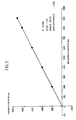
- FIG. 3 is a calibration curve obtained during tests performed at the manufacturing site to calibrate the Doppler transducer 4 using the equipment of FIG. 2 .
- a catheter-shaped probe 1 for measuring the speed of flow of a fluid F is manufactured in conventional manner.
- the Doppler transducer 4 is designed on manufacture to present an angle of inclination for its ultrasound beam of 60° relative to the longitudinal axis x-x′ of the probe 1 .
- the Doppler transducer 4 operates in combination with an additional transducer 5 , for example and preferably in the context of measuring the flow speed of blood in a blood vessel, in this case the aorta 10 , a transducer which produces a narrow beam 5 a as described in document U.S. Pat. No. 5,479,928, with the transducer being placed parallel to the longitudinal axis of the probe so that its ultrasound beam extends perpendicularly to the longitudinal axis of the probe for the purpose of measuring the diameter and thus the flow section S of the duct 10 in which there flows the fluid F whose speed is to be measured, as described in the above-specified documents and as is also known to the person skilled in the art, in particular from those documents.
- reference numeral 1 represents the outside portion of the catheter-shaped probe which, when installed in a duct, in this case the esophagus 13 facing a blood vessel, in this case the aorta 10 , will take up a position that is fixed once the inflatable balloon 6 has been inflated in the manner known to the person skilled in the art.
- the catheter-forming probe 1 has an internal flexible cable 2 connected at one of its ends to the support block 3 on which the ultrasound transducers 4 and 5 are mounted.
- the transducers 4 and 5 are connected to an electric cable 7 placed in the probe 1 at its distal end and leaving the probe 1 on the outside for connection to a computer center or unit for controlling the transducers and for processing the signals they deliver.
- the external end of the flexible cable 2 remote from its end connected to the support block 3 , is connected to a drive member 9 , in this case modified in accordance with the present invention to be in the form of a handle suitable for being taken hold of to rotate the flexible cable 2 appropriately about its own axis so as to rotate the support block 3 , thereby directly turning the ultrasound beams 4 a and 5 a respectively of the transducers 4 and 5 appropriately relative to the duct 10 such as the aorta in which it is desired to measure the flow speed of the fluid F, in this case blood.
- the control and computer unit 8 comprises, as described in U.S. Pat. No.
- means 14 connected to the transducer 5 by a link 7 1 designed to determine the amplitudes of echo signals received by the narrow beam transducer 5 . These determination means 14 are connected to means 15 designed to detect the amplitude maxima in the reflected signals.
- Means 16 are also provided in the control and computer unit 8 to determine the range P 2 -P 1 circumscribing the section of the duct 10 at two opposite extreme points by taking account solely of the echoes of the transducer 5 coming from said range P 2 -P 1 .
- the means 16 are connected to the means 15 in order to determine the range d 2 -d 1 which corresponds to the two extreme points of the duct, in this case the aorta 10 , as detected by the amplitude maxima in the reflected echoes of the signals from the transducer 5 .
- the range d 2 -d 1 it is possible to calculate the flow section S since it is conventional to consider the duct 10 , in this case the aorta, to be circular in section.
- the means 16 which conventionally comprise a microcomputer with appropriate software also takes account of the angle of inclination ⁇ between the two beams 4 a and 5 a as shown in FIG. 1 and as known, in particular by construction.
- These means 16 control selection means 17 connected to the transducer 4 by a link 7 2 .
- the means 17 make it possible to select only those echoes of signals from the transducer 4 which are obtained over a response time interval corresponding to the range P 2 -P 1 .
- the selection means 17 are connected to conventional signal processing means 19 for obtaining a Doppler signal.
- These processing means 19 are also connected to conventional means 20 suitable for determining the mean speed V m of the fluid F, in this case blood, as averaged over the section S of the duct 10 , in this case the aorta.
- the unit 8 also has means 21 suitable for measuring the energy backscattered by moving particles, in this case red corpuscles in the blood.
- the output from the measuring means 21 is connected to means 22 designed to allow backscattered energy to pass through at one or more defined instants, in particular during systole when measuring blood speed, said means 22 also being connected to means 23 suitable for determining those defined instants, and in particular the instant at which systole occurs when blood is being measured.
- the means 22 deliver the value of the backscattered energy E S during systole when measuring blood.
- the correction factor K is determined by correction means 24 connected to the means 21 and 22 .
- the correction means 24 weight the factor K by an empirical correction factor which takes account of the technical characteristics of the transducer 4 in use and of the means 19 , in particular the minimum value of the speeds detected and the passband of the emitted Doppler signal.
- the correction means 24 are connected to means 25 that are also connected to the means 20 for determining the mean speed over the section.
- the means 25 make it possible to calculate a corrected mean speed V c using the values for the mean speed over the area and the correction factor K, and thus to calculate the flow rate of the fluid F, in this case blood, moving through the localized area S D , given knowledge of the section S of the duct 10 , in this case the aorta, as measured from distances D 1 and D 2 obtained by the transducer 5 disposed perpendicular to the duct 10 .
- n is a number constituting another corrector factor
- k is a correction factor as defined above depending on the technical characteristics of the Doppler transducer 4 and of the means that emit, receive, measure, and process the signals associated with the Doppler effect transducer 4 , including the measurement means 19 .
- the apparatus that comprises the probe 1 and its control and computer unit 8 to further comprise, in accordance with the present invention, a programmable memory 50 which is associated with the Doppler transducer 4 and which contains at least one data item for correcting the Doppler signal transmitted from the transducer 4 to the transducer control and computer unit 8 , and in particular to its computation means 16 .
- programmable memories are commercially available, e.g. memories known as EEPROMs or memories known as flash memories.
- the computation means 16 conventionally comprise, for example, a computer or a microcomputer having appropriate software for controlling it. In this context, the computation means 16 also has software incorporating said signal correction data item as recorded in the programmable memory 50 each time it performs computations on each speed measurement as obtained by means of the Doppler transducer 4 .
- this signal correction data item comprises at least the angle ⁇ at which the ultrasound beam is emitted by the Doppler transducer 4 .
- This angle is determined by performing a plurality of speed measurements using the Doppler transducer 4 on a fluid that is flowing along a calibrated duct of known diameter at a known speed of fluid flow which is preferably adjusted to a different known speed value for each measurement.
- ⁇ F the frequency difference between reception and emission, as a result of the Doppler effect
- F emit the frequency at which the ultrasound beam is emitted by the Doppler transducer
- C the speed of propagation of sound in the medium, e.g. in blood, equal to 1584 meters per second (m/s);
- ⁇ the angle at which the ultrasound beam is emitted by the Doppler transducer 4 relative to the longitudinal axis x-x′ of the probe 1 .
- the exact value of the angle at which the ultrasound beam is emitted by the Doppler transducer is obtained, i.e. as emitted by the probe.
- This angle ⁇ is thus incorporated in the programmable memory 50 for subsequent use by the computer unit 8 in calculating the real speed when measuring the speed of a fluid F flowing along a given duct 10 , in particular and preferably the aorta.
- the programmable memory is incorporated in or forms an integral portion of the probe 1 , thus having the advantage of constituting a “signature” for the probe.
- the programmable memory 50 also includes data concerning the sensitivity of the Doppler transducer 4 .
- This sensitivity data is obtained by programming the transducer control and computer unit 8 which, on each speed measurement, memorizes the amplitude of the signal received by the transducer after a Doppler emission, and takes an average over a plurality of measurements to calculate a reference sensitivity which is subsequently stored by the computer unit 8 in the programmable memory 50 and which is subsequently used as an initial reference sensitivity, the control and computer unit 8 subsequently and on each measurement recalculating the sensitivity of the Doppler transducer 4 and preferably also taking an average over a plurality of measurements, which it compares with the initial sensitivity, such that in the event of too great a difference, e.g.
- control and computer unit 8 issues a signal to the user to inform the user that there has been a loss of sensitivity.
- this signal can be an alarm, or a warning lamp, or a message.
- the rms value of the received electrical signal is about 50 ⁇ V for a conventional Doppler transducer 4 having dimensions of 3 mm ⁇ 4 mm and operating at about 5 MHz.
- the sensitivity of the additional transducer 5 is measured in the same manner, and this sensitivity measurement is also put into the programmable memory 50 so as to be able to give the user a similar signal concerning loss of sensitivity for this additional transducer, when appropriate.
- the initial sensitivity value may be 80 ⁇ V for an additional transducer 5 having a diameter of 3 mm and operating at a frequency of about 10 MHz.
- the invention makes it possible to monitor proper operation of the Doppler transducer 4 and possibly also of the additional transducer 5 effectively and to inform the user, or to monitor any other additional transducer that may be present on the probe.
- any commercially available programmable memory can be used.
- Examples of programmable memories that are presently commercially available are electrically erasable programmable random memories (EEPROMs) or indeed flash memories, and the invention can be used with any other programmable memory that may become available in the future.
- EEPROMs electrically erasable programmable random memories
- flash memories indeed flash memories
- FIG. 2 there is shown a diagram representing the operation of calibrating the FIG. 1 probe incorporating the programmable memory of the invention for the purpose of determining the characteristics of the Doppler transducer actually mounted in the probe, which characteristics are subsequently used for correcting the measured flow speed of the fluid F circulating in the duct 10 .
- a tank 60 is provided that is filled with a liquid, such as water, and that has a well 60 a which is filled with water and in which the active end of the probe 1 having the said transducers 4 and 5 is inserted.
- the well 60 a thus symbolizes the esophagus 13 of a human body.
- the tank 60 has immersed therein a closed circuit 62 for circulating a fluid 63 , such as water containing starch, so that the closed circuit 62 symbolizes the aorta 10 in which blood is flowing, and the flow section S 1 of the closed circuit 61 is calibrated, e.g. to a value S 1 that is close to the flow section S of the blood vessel, so as to enable tests to be performed under conditions that are close to the genuine working conditions of the probe 1 when in the human body.
- the speed at which the liquid 63 flows round the closed circuit 62 is determined by acting on a pump or any other similar device for adjusting the flow speed of the liquid 63 in the closed circuit 62 .
- the flow speed of said fluid is read by any appropriate flow measuring apparatus represented by 66 .
- the probe is connected to the control unit 8 which contains in particular the computation means 16 such as a computer or a microcomputer.
- a screen 68 is generally also provided on which various parameters are displayed together with the results obtained.
- the tests performed comprise fixing the flow speed of the liquid 63 round the closed circuit 62 at various different values by means of the flow meter or spinner 64 , thus making it possible to plot a calibration curve for the Doppler transducer 4 .
- the ordinate corresponds to reference measurements as provided by the flow rate measuring apparatus 66 (FIG. 2 );
- the curve and the estimated angle and linear regression correlation relating to the ultrasound beam are displayed on the screen 68 (FIG. 2 ).
- the control unit 8 (FIG. 2) automatically saves the estimated angle (59.67° in this example) for the ultrasound beam in the memory of the probe 50 (FIG. 2 ).
- ⁇ est . Arc ⁇ ⁇ Cos ⁇ ⁇ ( reference flow rate measured flow rate ⁇ Cos ⁇ ⁇ ( ⁇ ideal ) )
Abstract
Description


Claims (14)
Priority Applications (3)
| Application Number | Priority Date | Filing Date | Title |
|---|---|---|---|
| US09/922,603 US6506159B2 (en) | 1999-10-14 | 2001-08-03 | Method and apparatus for improving the accuracy with which the speed of a fluid is measured |
| US10/340,552 US6905469B2 (en) | 1999-10-14 | 2003-01-10 | Method and apparatus for improving the accuracy with which the speed of a fluid is measured |
| US11/123,856 US20050256408A1 (en) | 1999-10-14 | 2005-05-06 | Method and apparatus for improving the accuracy with which the speed of a fluid is measured |
Applications Claiming Priority (4)
| Application Number | Priority Date | Filing Date | Title |
|---|---|---|---|
| FR9912815A FR2799633B1 (en) | 1999-10-14 | 1999-10-14 | METHOD AND DEVICE FOR IMPROVING THE PRECISION OF MEASUREMENT OF A SPEED OF A FLUID |
| FRFR9912815 | 1999-10-14 | ||
| US09/522,089 US6287260B1 (en) | 1998-10-14 | 2000-03-10 | Method and apparatus for improving the accuracy with which the speed of a fluid is measured |
| US09/922,603 US6506159B2 (en) | 1999-10-14 | 2001-08-03 | Method and apparatus for improving the accuracy with which the speed of a fluid is measured |
Related Parent Applications (2)
| Application Number | Title | Priority Date | Filing Date |
|---|---|---|---|
| US09/522,089 Continuation US6287260B1 (en) | 1998-10-14 | 2000-03-10 | Method and apparatus for improving the accuracy with which the speed of a fluid is measured |
| US09/522,089 Continuation-In-Part US6287260B1 (en) | 1998-10-14 | 2000-03-10 | Method and apparatus for improving the accuracy with which the speed of a fluid is measured |
Related Child Applications (1)
| Application Number | Title | Priority Date | Filing Date |
|---|---|---|---|
| US10/340,552 Continuation US6905469B2 (en) | 1999-10-14 | 2003-01-10 | Method and apparatus for improving the accuracy with which the speed of a fluid is measured |
Publications (2)
| Publication Number | Publication Date |
|---|---|
| US20020042575A1 US20020042575A1 (en) | 2002-04-11 |
| US6506159B2 true US6506159B2 (en) | 2003-01-14 |
Family
ID=9550922
Family Applications (4)
| Application Number | Title | Priority Date | Filing Date |
|---|---|---|---|
| US09/522,089 Expired - Lifetime US6287260B1 (en) | 1998-10-14 | 2000-03-10 | Method and apparatus for improving the accuracy with which the speed of a fluid is measured |
| US09/922,603 Expired - Lifetime US6506159B2 (en) | 1999-10-14 | 2001-08-03 | Method and apparatus for improving the accuracy with which the speed of a fluid is measured |
| US10/340,552 Expired - Lifetime US6905469B2 (en) | 1999-10-14 | 2003-01-10 | Method and apparatus for improving the accuracy with which the speed of a fluid is measured |
| US11/123,856 Abandoned US20050256408A1 (en) | 1999-10-14 | 2005-05-06 | Method and apparatus for improving the accuracy with which the speed of a fluid is measured |
Family Applications Before (1)
| Application Number | Title | Priority Date | Filing Date |
|---|---|---|---|
| US09/522,089 Expired - Lifetime US6287260B1 (en) | 1998-10-14 | 2000-03-10 | Method and apparatus for improving the accuracy with which the speed of a fluid is measured |
Family Applications After (2)
| Application Number | Title | Priority Date | Filing Date |
|---|---|---|---|
| US10/340,552 Expired - Lifetime US6905469B2 (en) | 1999-10-14 | 2003-01-10 | Method and apparatus for improving the accuracy with which the speed of a fluid is measured |
| US11/123,856 Abandoned US20050256408A1 (en) | 1999-10-14 | 2005-05-06 | Method and apparatus for improving the accuracy with which the speed of a fluid is measured |
Country Status (9)
| Country | Link |
|---|---|
| US (4) | US6287260B1 (en) |
| EP (1) | EP1223864B1 (en) |
| JP (1) | JP2003511144A (en) |
| AT (1) | ATE439088T1 (en) |
| AU (1) | AU3740900A (en) |
| CA (1) | CA2386144A1 (en) |
| DE (1) | DE60042747D1 (en) |
| FR (1) | FR2799633B1 (en) |
| WO (1) | WO2001026553A1 (en) |
Cited By (35)
| Publication number | Priority date | Publication date | Assignee | Title |
|---|---|---|---|---|
| US20030158485A1 (en) * | 1999-10-14 | 2003-08-21 | Gerard Hascoet | Method and apparatus for improving the accuracy with which the speed of a fluid is measured |
| US8801693B2 (en) | 2010-10-29 | 2014-08-12 | C. R. Bard, Inc. | Bioimpedance-assisted placement of a medical device |
| US9265443B2 (en) | 2006-10-23 | 2016-02-23 | Bard Access Systems, Inc. | Method of locating the tip of a central venous catheter |
| US9339206B2 (en) | 2009-06-12 | 2016-05-17 | Bard Access Systems, Inc. | Adaptor for endovascular electrocardiography |
| US9345422B2 (en) | 2006-10-23 | 2016-05-24 | Bard Acess Systems, Inc. | Method of locating the tip of a central venous catheter |
| US9445743B2 (en) | 2003-02-21 | 2016-09-20 | 3Dt Holdings, Llc | Methods for generating luminal organ profiles using impedance |
| US9445734B2 (en) | 2009-06-12 | 2016-09-20 | Bard Access Systems, Inc. | Devices and methods for endovascular electrography |
| US9456766B2 (en) | 2007-11-26 | 2016-10-04 | C. R. Bard, Inc. | Apparatus for use with needle insertion guidance system |
| US9492097B2 (en) | 2007-11-26 | 2016-11-15 | C. R. Bard, Inc. | Needle length determination and calibration for insertion guidance system |
| US9521961B2 (en) | 2007-11-26 | 2016-12-20 | C. R. Bard, Inc. | Systems and methods for guiding a medical instrument |
| US9526440B2 (en) | 2007-11-26 | 2016-12-27 | C.R. Bard, Inc. | System for placement of a catheter including a signal-generating stylet |
| US9532724B2 (en) | 2009-06-12 | 2017-01-03 | Bard Access Systems, Inc. | Apparatus and method for catheter navigation using endovascular energy mapping |
| US9549685B2 (en) | 2007-11-26 | 2017-01-24 | C. R. Bard, Inc. | Apparatus and display methods relating to intravascular placement of a catheter |
| US9554716B2 (en) | 2007-11-26 | 2017-01-31 | C. R. Bard, Inc. | Insertion guidance system for needles and medical components |
| US9636031B2 (en) | 2007-11-26 | 2017-05-02 | C.R. Bard, Inc. | Stylets for use with apparatus for intravascular placement of a catheter |
| US9649048B2 (en) | 2007-11-26 | 2017-05-16 | C. R. Bard, Inc. | Systems and methods for breaching a sterile field for intravascular placement of a catheter |
| US9681823B2 (en) | 2007-11-26 | 2017-06-20 | C. R. Bard, Inc. | Integrated system for intravascular placement of a catheter |
| US9839372B2 (en) | 2014-02-06 | 2017-12-12 | C. R. Bard, Inc. | Systems and methods for guidance and placement of an intravascular device |
| US9901714B2 (en) | 2008-08-22 | 2018-02-27 | C. R. Bard, Inc. | Catheter assembly including ECG sensor and magnetic assemblies |
| US9907513B2 (en) | 2008-10-07 | 2018-03-06 | Bard Access Systems, Inc. | Percutaneous magnetic gastrostomy |
| US10004875B2 (en) | 2005-08-24 | 2018-06-26 | C. R. Bard, Inc. | Stylet apparatuses and methods of manufacture |
| US10046139B2 (en) | 2010-08-20 | 2018-08-14 | C. R. Bard, Inc. | Reconfirmation of ECG-assisted catheter tip placement |
| US10159531B2 (en) | 2012-04-05 | 2018-12-25 | C. R. Bard, Inc. | Apparatus and methods relating to intravascular positioning of distal end of catheter |
| US10172538B2 (en) | 2003-02-21 | 2019-01-08 | 3Dt Holdings, Llc | Body lumen junction localization |
| US10231643B2 (en) | 2009-06-12 | 2019-03-19 | Bard Access Systems, Inc. | Apparatus and method for catheter navigation and tip location |
| US10349890B2 (en) | 2015-06-26 | 2019-07-16 | C. R. Bard, Inc. | Connector interface for ECG-based catheter positioning system |
| US10413211B2 (en) | 2003-02-21 | 2019-09-17 | 3Dt Holdings, Llc | Systems, devices, and methods for mapping organ profiles |
| US10449330B2 (en) | 2007-11-26 | 2019-10-22 | C. R. Bard, Inc. | Magnetic element-equipped needle assemblies |
| US10524691B2 (en) | 2007-11-26 | 2020-01-07 | C. R. Bard, Inc. | Needle assembly including an aligned magnetic element |
| US10751509B2 (en) | 2007-11-26 | 2020-08-25 | C. R. Bard, Inc. | Iconic representations for guidance of an indwelling medical device |
| US10973584B2 (en) | 2015-01-19 | 2021-04-13 | Bard Access Systems, Inc. | Device and method for vascular access |
| US10992079B2 (en) | 2018-10-16 | 2021-04-27 | Bard Access Systems, Inc. | Safety-equipped connection systems and methods thereof for establishing electrical connections |
| US11000207B2 (en) | 2016-01-29 | 2021-05-11 | C. R. Bard, Inc. | Multiple coil system for tracking a medical device |
| US11000205B2 (en) | 2012-04-05 | 2021-05-11 | Bard Access Systems, Inc. | Devices and systems for navigation and positioning a central venous catheter within a patient |
| US11759268B2 (en) | 2012-04-05 | 2023-09-19 | C. R. Bard, Inc. | Apparatus and methods relating to intravascular positioning of distal end of catheter |
Families Citing this family (6)
| Publication number | Priority date | Publication date | Assignee | Title |
|---|---|---|---|---|
| US20050187468A1 (en) * | 2001-11-29 | 2005-08-25 | Atlas Glen M. | Modified esophageal doppler monitor methods for measuring aortic dp/dt and pulse wave velocity |
| EP1915913B1 (en) * | 2006-10-23 | 2015-11-18 | Nestec S.A. | Taste and flavour modulation by biotransformation in milk products |
| US20090037201A1 (en) * | 2007-08-02 | 2009-02-05 | Patrick Michael Cravens | Care Provider Online Interview System and Method |
| JP5903050B2 (en) * | 2010-02-09 | 2016-04-13 | コーニンクレッカ フィリップス エヌ ヴェKoninklijke Philips N.V. | Apparatus and system for imaging and treatment using optical position sensing |
| DE102012112516A1 (en) * | 2012-12-18 | 2014-06-18 | Endress + Hauser Flowtec Ag | Method for verifying the reliability of measured data measured by an ultrasonic flow measurement according to the transit time difference method and ultrasonic flowmeter |
| WO2016145524A1 (en) * | 2015-03-16 | 2016-09-22 | Darkvision Technologies Inc. | Device and method to image flow in oil and gas wells using phased array doppler ultrasound |
Citations (3)
| Publication number | Priority date | Publication date | Assignee | Title |
|---|---|---|---|---|
| US5409010A (en) * | 1992-05-19 | 1995-04-25 | Board Of Regents Of The University Of Washington | Vector doppler medical devices for blood velocity studies |
| US5488953A (en) * | 1994-04-15 | 1996-02-06 | Ecocath, Inc. | Diffracting doppler-transducer |
| US6261233B1 (en) * | 1996-01-05 | 2001-07-17 | Sunlight Medical Ltd. | Method and device for a blood velocity determination |
Family Cites Families (18)
| Publication number | Priority date | Publication date | Assignee | Title |
|---|---|---|---|---|
| US3864661A (en) * | 1973-09-10 | 1975-02-04 | Rohe & 0 Scient Corp | Ultrascope |
| FR2424733A1 (en) * | 1978-05-05 | 1979-11-30 | Inst Nat Sante Rech Med | Flexible ultra-sonic probe - has inflatable plastics envelope over section of shaft to hold emitter in position without it touching sides of oesophagus |
| JPH0734797B2 (en) * | 1986-12-18 | 1995-04-19 | 株式会社日立メデイコ | Ultrasonic diagnostic equipment |
| US4893284A (en) * | 1988-05-27 | 1990-01-09 | General Electric Company | Calibration of phased array ultrasound probe |
| US5190522A (en) * | 1989-01-20 | 1993-03-02 | Institute Of Biocybernetics And Biomedical Engineering P.A.S. | Device for monitoring the operation of a delivery system and the method of use thereof |
| US5251631A (en) * | 1990-11-07 | 1993-10-12 | Kabushiki Kaisha Toshiba | Ultrasonic imaging apparatus |
| DE69333503T2 (en) * | 1992-09-21 | 2004-11-18 | Institut National De La Santé Et De La Recherche Médicale (Inserm) | INTRACORPORAL PROBE FOR DETERMINING THE SPEED OF A LIQUID, IN PARTICULAR THE FLOW THROUGH THE AORTA |
| FR2695999B1 (en) * | 1992-09-21 | 1994-12-30 | Inst Nat Sante Rech Med | Ultrasonic probe to accurately determine the speed of a liquid and, in particular, the aortic flow. |
| US5333614A (en) * | 1992-09-28 | 1994-08-02 | Feiring Andrew J | Measurement of absolute vascular flow |
| ZA948393B (en) * | 1993-11-01 | 1995-06-26 | Polartechnics Ltd | Method and apparatus for tissue type recognition |
| FR2715725B1 (en) * | 1994-02-01 | 1996-03-29 | Schlumberger Ind Sa | Method and device for determining a physical parameter represented by the evolution over time of a physical quantity. |
| JPH07289553A (en) * | 1994-04-22 | 1995-11-07 | Hitachi Medical Corp | Ultrasonic tomographic system |
| JP3713329B2 (en) | 1996-06-04 | 2005-11-09 | 株式会社東芝 | Ultrasonic Doppler diagnostic device |
| US5720288A (en) * | 1996-09-24 | 1998-02-24 | Siemens Medical Systems, Inc. | Method and apparatus for displaying an ultrasound image with an improved dynamic range |
| US5891041A (en) * | 1996-11-27 | 1999-04-06 | Hitachi Medical Corporation | Ultrasonic imaging system adapted for use with ultrasonic probes having different center frequencies |
| US6023977A (en) * | 1997-08-01 | 2000-02-15 | Acuson Corporation | Ultrasonic imaging aberration correction system and method |
| FR2799633B1 (en) * | 1999-10-14 | 2002-03-22 | Sometec | METHOD AND DEVICE FOR IMPROVING THE PRECISION OF MEASUREMENT OF A SPEED OF A FLUID |
| US6364839B1 (en) * | 1999-05-04 | 2002-04-02 | Sonosite, Inc. | Ultrasound diagnostic instrument having software in detachable scanhead |
-
1999
- 1999-10-14 FR FR9912815A patent/FR2799633B1/en not_active Expired - Fee Related
-
2000
- 2000-03-10 US US09/522,089 patent/US6287260B1/en not_active Expired - Lifetime
- 2000-03-10 DE DE60042747T patent/DE60042747D1/en not_active Expired - Lifetime
- 2000-03-10 AU AU37409/00A patent/AU3740900A/en not_active Abandoned
- 2000-03-10 CA CA002386144A patent/CA2386144A1/en not_active Abandoned
- 2000-03-10 AT AT00916281T patent/ATE439088T1/en not_active IP Right Cessation
- 2000-03-10 JP JP2001529347A patent/JP2003511144A/en active Pending
- 2000-03-10 WO PCT/US2000/006487 patent/WO2001026553A1/en active Application Filing
- 2000-03-10 EP EP00916281A patent/EP1223864B1/en not_active Expired - Lifetime
-
2001
- 2001-08-03 US US09/922,603 patent/US6506159B2/en not_active Expired - Lifetime
-
2003
- 2003-01-10 US US10/340,552 patent/US6905469B2/en not_active Expired - Lifetime
-
2005
- 2005-05-06 US US11/123,856 patent/US20050256408A1/en not_active Abandoned
Patent Citations (3)
| Publication number | Priority date | Publication date | Assignee | Title |
|---|---|---|---|---|
| US5409010A (en) * | 1992-05-19 | 1995-04-25 | Board Of Regents Of The University Of Washington | Vector doppler medical devices for blood velocity studies |
| US5488953A (en) * | 1994-04-15 | 1996-02-06 | Ecocath, Inc. | Diffracting doppler-transducer |
| US6261233B1 (en) * | 1996-01-05 | 2001-07-17 | Sunlight Medical Ltd. | Method and device for a blood velocity determination |
Cited By (66)
| Publication number | Priority date | Publication date | Assignee | Title |
|---|---|---|---|---|
| US20030158485A1 (en) * | 1999-10-14 | 2003-08-21 | Gerard Hascoet | Method and apparatus for improving the accuracy with which the speed of a fluid is measured |
| US6905469B2 (en) * | 1999-10-14 | 2005-06-14 | Arrow International Investment Corp. | Method and apparatus for improving the accuracy with which the speed of a fluid is measured |
| US20050256408A1 (en) * | 1999-10-14 | 2005-11-17 | Gerard Hascoet | Method and apparatus for improving the accuracy with which the speed of a fluid is measured |
| US10524685B2 (en) | 2003-02-21 | 2020-01-07 | 3Dt Holdings, Llc | Methods for generating luminal organ profiles using impedance |
| US11490829B2 (en) | 2003-02-21 | 2022-11-08 | 3Dt Holdings, Llc | Systems, devices, and methods for mapping organ profiles |
| US9445743B2 (en) | 2003-02-21 | 2016-09-20 | 3Dt Holdings, Llc | Methods for generating luminal organ profiles using impedance |
| US10413211B2 (en) | 2003-02-21 | 2019-09-17 | 3Dt Holdings, Llc | Systems, devices, and methods for mapping organ profiles |
| US11510589B2 (en) | 2003-02-21 | 2022-11-29 | 3Dt Holdings, Llc | Body lumen junction localization |
| US10172538B2 (en) | 2003-02-21 | 2019-01-08 | 3Dt Holdings, Llc | Body lumen junction localization |
| US11207496B2 (en) | 2005-08-24 | 2021-12-28 | C. R. Bard, Inc. | Stylet apparatuses and methods of manufacture |
| US10004875B2 (en) | 2005-08-24 | 2018-06-26 | C. R. Bard, Inc. | Stylet apparatuses and methods of manufacture |
| US9265443B2 (en) | 2006-10-23 | 2016-02-23 | Bard Access Systems, Inc. | Method of locating the tip of a central venous catheter |
| US9345422B2 (en) | 2006-10-23 | 2016-05-24 | Bard Acess Systems, Inc. | Method of locating the tip of a central venous catheter |
| US9833169B2 (en) | 2006-10-23 | 2017-12-05 | Bard Access Systems, Inc. | Method of locating the tip of a central venous catheter |
| US10238418B2 (en) | 2007-11-26 | 2019-03-26 | C. R. Bard, Inc. | Apparatus for use with needle insertion guidance system |
| US10105121B2 (en) | 2007-11-26 | 2018-10-23 | C. R. Bard, Inc. | System for placement of a catheter including a signal-generating stylet |
| US9554716B2 (en) | 2007-11-26 | 2017-01-31 | C. R. Bard, Inc. | Insertion guidance system for needles and medical components |
| US9636031B2 (en) | 2007-11-26 | 2017-05-02 | C.R. Bard, Inc. | Stylets for use with apparatus for intravascular placement of a catheter |
| US9649048B2 (en) | 2007-11-26 | 2017-05-16 | C. R. Bard, Inc. | Systems and methods for breaching a sterile field for intravascular placement of a catheter |
| US9681823B2 (en) | 2007-11-26 | 2017-06-20 | C. R. Bard, Inc. | Integrated system for intravascular placement of a catheter |
| US11123099B2 (en) | 2007-11-26 | 2021-09-21 | C. R. Bard, Inc. | Apparatus for use with needle insertion guidance system |
| US11779240B2 (en) | 2007-11-26 | 2023-10-10 | C. R. Bard, Inc. | Systems and methods for breaching a sterile field for intravascular placement of a catheter |
| US10602958B2 (en) | 2007-11-26 | 2020-03-31 | C. R. Bard, Inc. | Systems and methods for guiding a medical instrument |
| US10524691B2 (en) | 2007-11-26 | 2020-01-07 | C. R. Bard, Inc. | Needle assembly including an aligned magnetic element |
| US9999371B2 (en) | 2007-11-26 | 2018-06-19 | C. R. Bard, Inc. | Integrated system for intravascular placement of a catheter |
| US9526440B2 (en) | 2007-11-26 | 2016-12-27 | C.R. Bard, Inc. | System for placement of a catheter including a signal-generating stylet |
| US9549685B2 (en) | 2007-11-26 | 2017-01-24 | C. R. Bard, Inc. | Apparatus and display methods relating to intravascular placement of a catheter |
| US10751509B2 (en) | 2007-11-26 | 2020-08-25 | C. R. Bard, Inc. | Iconic representations for guidance of an indwelling medical device |
| US11707205B2 (en) | 2007-11-26 | 2023-07-25 | C. R. Bard, Inc. | Integrated system for intravascular placement of a catheter |
| US10165962B2 (en) | 2007-11-26 | 2019-01-01 | C. R. Bard, Inc. | Integrated systems for intravascular placement of a catheter |
| US9521961B2 (en) | 2007-11-26 | 2016-12-20 | C. R. Bard, Inc. | Systems and methods for guiding a medical instrument |
| US10231753B2 (en) | 2007-11-26 | 2019-03-19 | C. R. Bard, Inc. | Insertion guidance system for needles and medical components |
| US11134915B2 (en) | 2007-11-26 | 2021-10-05 | C. R. Bard, Inc. | System for placement of a catheter including a signal-generating stylet |
| US9492097B2 (en) | 2007-11-26 | 2016-11-15 | C. R. Bard, Inc. | Needle length determination and calibration for insertion guidance system |
| US10966630B2 (en) | 2007-11-26 | 2021-04-06 | C. R. Bard, Inc. | Integrated system for intravascular placement of a catheter |
| US10342575B2 (en) | 2007-11-26 | 2019-07-09 | C. R. Bard, Inc. | Apparatus for use with needle insertion guidance system |
| US11529070B2 (en) | 2007-11-26 | 2022-12-20 | C. R. Bard, Inc. | System and methods for guiding a medical instrument |
| US9456766B2 (en) | 2007-11-26 | 2016-10-04 | C. R. Bard, Inc. | Apparatus for use with needle insertion guidance system |
| US10449330B2 (en) | 2007-11-26 | 2019-10-22 | C. R. Bard, Inc. | Magnetic element-equipped needle assemblies |
| US10849695B2 (en) | 2007-11-26 | 2020-12-01 | C. R. Bard, Inc. | Systems and methods for breaching a sterile field for intravascular placement of a catheter |
| US11027101B2 (en) | 2008-08-22 | 2021-06-08 | C. R. Bard, Inc. | Catheter assembly including ECG sensor and magnetic assemblies |
| US9901714B2 (en) | 2008-08-22 | 2018-02-27 | C. R. Bard, Inc. | Catheter assembly including ECG sensor and magnetic assemblies |
| US9907513B2 (en) | 2008-10-07 | 2018-03-06 | Bard Access Systems, Inc. | Percutaneous magnetic gastrostomy |
| US9445734B2 (en) | 2009-06-12 | 2016-09-20 | Bard Access Systems, Inc. | Devices and methods for endovascular electrography |
| US9339206B2 (en) | 2009-06-12 | 2016-05-17 | Bard Access Systems, Inc. | Adaptor for endovascular electrocardiography |
| US10912488B2 (en) | 2009-06-12 | 2021-02-09 | Bard Access Systems, Inc. | Apparatus and method for catheter navigation and tip location |
| US10271762B2 (en) | 2009-06-12 | 2019-04-30 | Bard Access Systems, Inc. | Apparatus and method for catheter navigation using endovascular energy mapping |
| US11419517B2 (en) | 2009-06-12 | 2022-08-23 | Bard Access Systems, Inc. | Apparatus and method for catheter navigation using endovascular energy mapping |
| US10231643B2 (en) | 2009-06-12 | 2019-03-19 | Bard Access Systems, Inc. | Apparatus and method for catheter navigation and tip location |
| US9532724B2 (en) | 2009-06-12 | 2017-01-03 | Bard Access Systems, Inc. | Apparatus and method for catheter navigation using endovascular energy mapping |
| US10046139B2 (en) | 2010-08-20 | 2018-08-14 | C. R. Bard, Inc. | Reconfirmation of ECG-assisted catheter tip placement |
| US8801693B2 (en) | 2010-10-29 | 2014-08-12 | C. R. Bard, Inc. | Bioimpedance-assisted placement of a medical device |
| US9415188B2 (en) | 2010-10-29 | 2016-08-16 | C. R. Bard, Inc. | Bioimpedance-assisted placement of a medical device |
| US11759268B2 (en) | 2012-04-05 | 2023-09-19 | C. R. Bard, Inc. | Apparatus and methods relating to intravascular positioning of distal end of catheter |
| US10159531B2 (en) | 2012-04-05 | 2018-12-25 | C. R. Bard, Inc. | Apparatus and methods relating to intravascular positioning of distal end of catheter |
| US11172843B2 (en) | 2012-04-05 | 2021-11-16 | Bard Access Systems, Inc. | Devices and systems for navigation and positioning a central venous catheter within a patient |
| US11185374B2 (en) | 2012-04-05 | 2021-11-30 | C. R. Bard, Inc. | Apparatus and methods relating to intravascular positioning of distal end of catheter |
| US11000205B2 (en) | 2012-04-05 | 2021-05-11 | Bard Access Systems, Inc. | Devices and systems for navigation and positioning a central venous catheter within a patient |
| US10863920B2 (en) | 2014-02-06 | 2020-12-15 | C. R. Bard, Inc. | Systems and methods for guidance and placement of an intravascular device |
| US9839372B2 (en) | 2014-02-06 | 2017-12-12 | C. R. Bard, Inc. | Systems and methods for guidance and placement of an intravascular device |
| US10973584B2 (en) | 2015-01-19 | 2021-04-13 | Bard Access Systems, Inc. | Device and method for vascular access |
| US11026630B2 (en) | 2015-06-26 | 2021-06-08 | C. R. Bard, Inc. | Connector interface for ECG-based catheter positioning system |
| US10349890B2 (en) | 2015-06-26 | 2019-07-16 | C. R. Bard, Inc. | Connector interface for ECG-based catheter positioning system |
| US11000207B2 (en) | 2016-01-29 | 2021-05-11 | C. R. Bard, Inc. | Multiple coil system for tracking a medical device |
| US11621518B2 (en) | 2018-10-16 | 2023-04-04 | Bard Access Systems, Inc. | Safety-equipped connection systems and methods thereof for establishing electrical connections |
| US10992079B2 (en) | 2018-10-16 | 2021-04-27 | Bard Access Systems, Inc. | Safety-equipped connection systems and methods thereof for establishing electrical connections |
Also Published As
| Publication number | Publication date |
|---|---|
| US20030158485A1 (en) | 2003-08-21 |
| FR2799633A1 (en) | 2001-04-20 |
| AU3740900A (en) | 2001-04-23 |
| EP1223864B1 (en) | 2009-08-12 |
| US6287260B1 (en) | 2001-09-11 |
| ATE439088T1 (en) | 2009-08-15 |
| US20050256408A1 (en) | 2005-11-17 |
| EP1223864A1 (en) | 2002-07-24 |
| EP1223864A4 (en) | 2004-08-25 |
| US6905469B2 (en) | 2005-06-14 |
| CA2386144A1 (en) | 2001-04-19 |
| US20020042575A1 (en) | 2002-04-11 |
| WO2001026553A1 (en) | 2001-04-19 |
| FR2799633B1 (en) | 2002-03-22 |
| JP2003511144A (en) | 2003-03-25 |
| DE60042747D1 (en) | 2009-09-24 |
Similar Documents
| Publication | Publication Date | Title |
|---|---|---|
| US6506159B2 (en) | Method and apparatus for improving the accuracy with which the speed of a fluid is measured | |
| US6673020B2 (en) | Ultrasonic diagnostic apparatus | |
| US4947852A (en) | Apparatus and method for continuously measuring volumetric blood flow using multiple transducer and catheter for use therewith | |
| US5078148A (en) | Apparatus and method for continuously measuring volumetric blood flow using multiple transducers and catheter for use therewith | |
| US5836882A (en) | Method and apparatus of localizing an insertion end of a probe within a biotic structure | |
| EP0670146B1 (en) | Ultrasonic doppler blood flow monitoring system | |
| JPH11319107A (en) | Method for determing localization of catheter inside animal body, method for determing localization of catheter distal portion inside animal body and catheter device | |
| JPS62500703A (en) | Volumetric flow measurement in conduits that are not directly accessible | |
| US7186219B2 (en) | Calibration of a doppler velocimeter for stroke volume determination | |
| JPS63279826A (en) | Apparatus and method for measuring volumetric flow rate of blood in blood vessel | |
| WO2020030665A1 (en) | Interventional device positioning respective an ultrasound image plane | |
| EP3632333A1 (en) | Interventional device positioning respective an ultrasound image plane | |
| JP3694357B2 (en) | Ultrasonic diagnostic equipment | |
| JPH05137725A (en) | Ultrasonic doppler blood flow quantity monitor | |
| JP3470764B2 (en) | How to use an in-vivo probe to accurately measure fluid velocity, especially aortic flow | |
| JPH05228148A (en) | Ultrasonic transmission inspecting system | |
| Eriksson et al. | A microcirculation phantom for performance testing of blood perfusion measurement equipment | |
| JPH06327674A (en) | Measurement method for sound velocity in tissue | |
| EP1601291A1 (en) | Method and device for ultrasound measurement of blood flow | |
| US20040249284A1 (en) | Vector Doppler utilizing constancy of vector flow direction | |
| CN117731326A (en) | Automatic blood pressure monitoring method and system based on ultrasonic waves | |
| JPH05184569A (en) | Ultrasonic wave transmission inspection device | |
| JPS63221220A (en) | Tube for measurement of fluid information | |
| JPH03251239A (en) | Ultrasonic diagnostic device | |
| JPH04108434A (en) | Ultrasonic diagnostic device |
Legal Events
| Date | Code | Title | Description |
|---|---|---|---|
| STCF | Information on status: patent grant |
Free format text: PATENTED CASE |
|
| AS | Assignment |
Owner name: ARROW INTERNATIONAL INVESTMENT CORP., DELAWARE Free format text: ASSIGNMENT OF ASSIGNORS INTEREST;ASSIGNOR:ARROW INTERNATIONAL, INC.;REEL/FRAME:014990/0187 Effective date: 20040213 |
|
| FPAY | Fee payment |
Year of fee payment: 4 |
|
| FEPP | Fee payment procedure |
Free format text: PAYOR NUMBER ASSIGNED (ORIGINAL EVENT CODE: ASPN); ENTITY STATUS OF PATENT OWNER: LARGE ENTITY |
|
| FPAY | Fee payment |
Year of fee payment: 8 |
|
| SULP | Surcharge for late payment |
Year of fee payment: 7 |
|
| FPAY | Fee payment |
Year of fee payment: 12 |
|
| AS | Assignment |
Owner name: ARROW INTERNATIONAL, INC., PENNSYLVANIA Free format text: ASSIGNMENT OF ASSIGNORS INTEREST;ASSIGNORS:HASCOET, GERARD;PECHOUX, THIERRY;SIGNING DATES FROM 20000802 TO 20000811;REEL/FRAME:041197/0590 |
|
| AS | Assignment |
Owner name: JPMORGAN CHASE BANK, N.A., AS ADMINISTRATIVE AGENT Free format text: SECURITY INTEREST;ASSIGNOR:ARROW INTERNATIONAL INVESTMENT CORP.;REEL/FRAME:041759/0707 Effective date: 20170217 |
|
| AS | Assignment |
Owner name: ARROW INTERNATIONAL, INC., NORTH CAROLINA Free format text: MERGER;ASSIGNOR:ARROW INTERNATIONAL INVESTMENT CORP.;REEL/FRAME:049850/0476 Effective date: 20190101 |
|
| AS | Assignment |
Owner name: JPMORGAN CHASE BANK, N.A., AS ADMINISTRATIVE AGENT Free format text: SECURITY INTEREST;ASSIGNOR:ARROW INTERNATIONAL, INC.;REEL/FRAME:050619/0681 Effective date: 20190925 |
|
| AS | Assignment |
Owner name: ARROW INTERNATIONAL LLC, NORTH CAROLINA Free format text: CONVERSION AND CHANGE OF NAME;ASSIGNOR:ARROW INTERNATIONAL, INC.;REEL/FRAME:053754/0731 Effective date: 20200330 |