US6549882B1 - Mechanisms for providing and using a scripting language for flexibly simulationg a plurality of different network protocols - Google Patents
Mechanisms for providing and using a scripting language for flexibly simulationg a plurality of different network protocols Download PDFInfo
- Publication number
- US6549882B1 US6549882B1 US09/217,012 US21701298A US6549882B1 US 6549882 B1 US6549882 B1 US 6549882B1 US 21701298 A US21701298 A US 21701298A US 6549882 B1 US6549882 B1 US 6549882B1
- Authority
- US
- United States
- Prior art keywords
- packet
- tools
- program code
- sre
- state
- Prior art date
- Legal status (The legal status is an assumption and is not a legal conclusion. Google has not performed a legal analysis and makes no representation as to the accuracy of the status listed.)
- Expired - Lifetime
Links
Images


Classifications
-
- H—ELECTRICITY
- H04—ELECTRIC COMMUNICATION TECHNIQUE
- H04L—TRANSMISSION OF DIGITAL INFORMATION, e.g. TELEGRAPHIC COMMUNICATION
- H04L41/00—Arrangements for maintenance, administration or management of data switching networks, e.g. of packet switching networks
- H04L41/14—Network analysis or design
- H04L41/145—Network analysis or design involving simulating, designing, planning or modelling of a network
-
- H—ELECTRICITY
- H04—ELECTRIC COMMUNICATION TECHNIQUE
- H04L—TRANSMISSION OF DIGITAL INFORMATION, e.g. TELEGRAPHIC COMMUNICATION
- H04L43/00—Arrangements for monitoring or testing data switching networks
- H04L43/18—Protocol analysers
-
- H—ELECTRICITY
- H04—ELECTRIC COMMUNICATION TECHNIQUE
- H04L—TRANSMISSION OF DIGITAL INFORMATION, e.g. TELEGRAPHIC COMMUNICATION
- H04L43/00—Arrangements for monitoring or testing data switching networks
- H04L43/50—Testing arrangements
Definitions
- the present invention relates to computer networks. More particularly, the invention relates the testing and simulation of computer networks, and to a scripting language, also referred to as a stimulus/response engine, for modeling state machines used in the testing of computer network protocols.
- a scripting language also referred to as a stimulus/response engine
- Traffic on computer networks is composed of multiple protocol interactions which work in concert to provide connectivity, bandwidth utilization, content provisioning, security, and reliability. Often multiple protocols are required in the course of a transaction to achieve a network application objective. Emulating this behavior in the test lab without installing and configuring all of the devices and protocols involved in such a transaction is a significant challenge facing network equipment vendors and consumers.
- NTA network traffic analyzer
- Pagent PagentTM product developed by Cisco Systems, Inc. (“Cisco”).
- IOS® Cisco Internet Operating System
- NTAs like Pagent have limited utility as test systems since they are not able to respond to the content of test packets (“stimuli”), and cannot be programmed to provide test scenarios for a variety of protocols. Instead, an NTA is only able to generate, send, receive and count packets.
- Network testing tools have been developed which address sub-components of these protocols (individual protocol conformance test suites).
- Midnight Networks, Inc. has a tool, ANVL, which provides an application performance interface (API) set that can be used to create individual protocol conformance test suites.
- API application performance interface
- this tool is implemented in the computer language C, and requires a C development environment in order to be used.
- test system which can replicate the rich, dynamic protocol interactions and dialogues necessary to test and model behavior in network protocol stacks.
- the present invention meets this need by providing test systems, methods, and media which allow a user to script any type of test or model scenario based on a particular type of network traffic (e.g., protocol interaction).
- the script provides for the generation of packets (stimuli) which are used to provoke responses in order to model or test proper operation of one or more network protocols.
- the invention includes a scripting language, also referred to as a stimulus/response engine, which includes commands specifying a state change of a network device, and provides for the establishment of packet filters based on expected network traffic, receiving and matching arriving packets with packet filters, and, where there is a match, conducting actions specified by the user in the script.
- a stimulus/response engine (SRE) in accordance with the present invention is dynamic in that it accommodates patterns (packet filters) which are modified during test runs.
- the SRE is fully programmable by the user and thus can be used to design models and test scenarios for a variety of network protocols, including new protocols developed by the user for which no testing packages exist.
- a SRE in accordance with the present invention is built on a state machine model. Since many internet protocols are also defined in terms of state machine models, these protocols may be easily translated into a SRE script for testing and simulation purposes. As noted, a SRE in accordance with the present invention is scriptable, so that it may be modified and extended to test a variety of network protocols. A SRE in accordance with the present invention also uses a send/expect model in its scripting format.
- the present invention provides a method, implemented on a computing device, for simulating one or more network activities.
- the method involves providing program code for generating a model of one or more network devices.
- the program is written in a language that includes commands specifying a state change of a network device.
- the program code is then converted, preferably using an interpreter, to machine executable instructions for executing the model.
- the invention provides a computer program product including a computer-usable medium having computer-readable program code embodied thereon for effecting such a method.
- the invention provides a system for controlling the generation of a model of one or more network devices, with the aid of a network device.
- the system includes a converter that recognizes program code commands specifying a state change of a network device and converts such program code to produce a model of one or more network devices, and a network device operating system on which the program code runs.
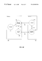
- FIG. 1 depicts a block diagram illustrating an example of network test system implementation in accordance with a preferred embodiment of the present invention.
- FIG. 2 illustrates a flow chart for a generic process of testing a suite of network protocols on a send/expect model, in accordance with a preferred embodiment of the present invention.
- FIG. 3A illustrates a flow diagram for a sample protocol to illustrate the organization of a SRE script and its dynamic scripting capacity, in accordance with a preferred embodiment of the present invention.
- FIG. 3B illustrates a state diagram for the sample protocol of FIG. 3A, illustrating the organization of a SRE script and its dynamic scripting capacity, in accordance with a preferred embodiment of the present invention.
- FIG. 4A depicts a block diagram illustrating a sample test system implementation for testing with layered protocol stacks, in accordance with a preferred embodiment of the present invention.
- FIG. 4B depicts a state diagram illustrating the organization a SRE script for testing the layered protocol stacks depicted in FIG. 4A, in accordance with a preferred embodiment of the present invention.
- FIG. 5 depicts a router hardware architecture that may be used to implement the systems and methods of the present invention.
- the present invention provides test systems, methods, and media which allow a user to write a script emulating any type of network traffic (e.g., protocol interaction) and to respond based on the stimuli provided (packets sent) by that script.
- Various aspects of the present invention incorporate an network device operating system (NDOS)-based scripting language, sometimes referred to as a stimulus/response engine.
- NDOS network device operating system
- a stimulus/response engine (SRE) in accordance with a preferred embodiment of the present is programmable and can respond based on the content a variety of stimuli provided in a test scenario.
- a preferred SRE in accordance with the invention is also dynamic, in that it accommodates packets modified during test runs. Further, since a SRE in accordance with the present invention is scriptable, it may be modified and extended to test a variety of network protocols.
- FIG. 1 illustrates a block diagram of a simple network test system in accordance with a preferred embodiment of the present invention.
- the system 100 includes two routers. It should be understood that a stimulus/response engine in accordance with the present invention may be implemented with a single router or with more than two routers, as explained in more detail below.
- a two router system is a particularly preferred test configuration since it offers the opportunity to test inter-device network protocols while minimizing the network structure required for testing.
- the test system features a router 102 which is configured to run a new version of an operating system for a network device.
- This router 102 may be referred to as the “router-under-test.”
- the router-under 102 test is connected to a second router 104 which is configured to run a stimulus/response engine in accordance with the present invention, together with a network traffic analyzer (NTA), such as Cisco's PagentTM, and a stable version of a NDOS, such as Cisco's IOS®, running on the router-under-test 102 .
- NTA network traffic analyzer
- the two routers 102 and 104 are connected by any networking medium 106 .
- a particularly preferred network medium is Ethernet (or Fast Ethernet or Gigabyte Ethernet). However, the medium may also be a serial link, for example.
- Each router 102 and 104 also normally has connected to it a console line 108 used for controlling the router. Further details relating to preferred implementations of the present invention and discussed below with reference to FIG
- SRE scripts are written and run on the testing router 104 resulting in packets being sent from the testing router 104 to the router-under-test 102 .
- the SRE establishes packet filters designed to match the response to the stimulus (packet(s)) sent expected from the router-under-test 102 .
- the SRE matches against the established filters. If there is a match, the action(s) associated with the matching packet filter are taken.
- a SRE in accordance with a preferred embodiment of the present invention is primarily based on two concepts: the state machine and the send/expect model. Since many internet protocols are also defined in terms of state machine models, these protocols may be easily translated into the SRE for testing and simulation purposes.
- a SRE model e.g., a SRE script
- the send/expect model is an idea adapted from Unix tc 1 /expect script, wherein a character string is sent, and another character string with a specific pattern is expected to come back in response.
- a packet filter is created and registered based on a packet to be sent out.
- the packet is then sent, and a packet (having a pattern) matching the filter is expected to come back.
- This send/expect model is adapted in the SRE in this way so that a quick response to a packet that has been sent by the router on which the SRE is running will not be missed while the packet filter is being established, as is discussed further below.
- a SRE in accordance with the present invention is not only able to verify proper operation against specifications to demonstrate conformance, but also to create a generic state machine-based, network-aware toolkit that can be used anytime there is a need to determine correct or incorrect operation of a set of network protocol interactions.
- the present invention provides a state machine engine and primatives for a variety of networking protocols. As such it does not constrain the user to create conformance validators.
- a SRE in accordance with the present invention allows any protocol or multi-protocol dialog to be replicated.
- a stimulus/response engine is a scripting language that allows a user to script a logical representation of virtually any network protocol.
- FIG. 2 depicts a flow chart for a generic process of testing a suite of network protocols on a send/expect model, in accordance with a preferred embodiment of the present invention.
- the process 200 begins at 201 , and at an optional step 202 a packet (stimulus) is sent from an SRE state machine.
- This step 202 is optional because frequently a networking environment includes one or more entities which act as “servers” and others that act as “clients.” Servers wait for requests to come in from clients.
- the SRE script used to conduct the test will typically begin with a the sending of a request (stimulus) to the server. However, if a server is being emulated (e.g., to test a client) will begin with waiting for a request; in this circumstance, the sending of a stimulus is unnecessary.
- a packet arrives in the SRE state machine, and at a step 206 the packet is matched against packet filters for expected packets. If an incoming packet matches a packet filter, one or more actions are taken at a step 208 , for example to indicate that the expected response to a stimulus was received. Actions may include, for example, printing a message, sending another packet, establishing a new packet filter, and/or transferring control of the state machine to another state. If no match is made, that also may be indicated by printing a message or invoking a timeout. The process ends at 210 .
- a SRE uses a network traffic analyzer (NTA) to assist in the construction and manipulation of packets and packet filters (packets used as filters).
- NTA network traffic analyzer
- packets are referred to as originating or existing in Pagent “workspace,” and certain Pagent commands and invoked to construct or modify packets or load SRE scripts. It should be understood, however, that Pagent is not an integral part of the SRE.
- a SRE merely interfaces with a NTA for its packet construction and manipulation requirements. Any NTA has packet construction and manipulation as primary functions.
- a description of the Pagent NTA functionalities relevant to SRE is provided herein. However, it should be understood that a SRE in accordance with the present invention may be used in conjunction with any compatible NTA.
- a SRE script is based on a state machine model. Therefore, a SRE script defines one or more states and transfers control between them. This is also referred to as a SRE process.
- SRE state definition makes use of SRE simple statements, SRE compound statements.
- SRE router command line interface (CLI) commands are used to assist in running a SRE script. These SRE commands and their use are described below.
- a SRE state definition is composed of an optional number of SRE simple statements (zero or more), and optionally followed by a SRE expect compound statement.
- the expect compound statement is composed of an optional number of packet compound statements, and optionally followed by a timeout compound statement.
- the packet compound statement is composed of a packet filter, and an optional interface parameter which specifies the interface on which to expect the response packet to be received. If no interface parameter is specified, SRE may use an interface defined in the packet filter, and if not defined, may use the default interface.
- the body of a packet compound statement is composed of any number of SRE simple statements, described below, including preferably a newstate statement (specifying a transition to a different state).
- the timeout compound statement specifies a timeout value to wait for a packet to be received. If no packet is received within the specified timeout value, the statements in the timeout compound statement are executed.
- the sample state definition includes one simple send statement up front in the CLIENT_ 1 state definition. As noted in the generic script, it is possible to optionally have zero or more simple statements.
- the send statement is followed by an expect compound statement, which is also optional. Inside the expect compound statement, there is one packet compound statement, which again is optional, and in this case includes print and newstate (transferring control to state CLIENT_ 2 ) simple statements. It is also possible to have a timeout compound statement inside a expect statement, as here containing a print simple statement.
- This command is used to define a SRE state.
- the scope of a state name is global. Thus, if the same state name has previously been defined, the SRE clears the old definition in favor of the new state definition.
- “StateName” may be any character string. The syntax for the command is as follows:
- This command is used to delete a SRE state.
- “StateName” may be any character string.
- the syntax for the command is as follows:
- This command is used to start a SRE state machine, and indicate that the initial state should be “StateName.”
- a SRE state machine runs by default in the background, unless “foreground” is specified.
- the syntax for the command is as follows:
- This command is used to stop a SRE state machine.
- a particular StateName, Process ID, or “*”, which means stop all SRE processes, may be specified.
- the syntax for the command is as follows:
- This command is used to display the SRE processes currently running.
- a particular StateName, Process ID, or “*”, which means display all SRE processes, may be specified.
- the syntax for the command is as follows:
- This command is used to display runtime information for SRE processes currently running.
- a particular StateName, Process ID, or “*”, which means display all SRE process runtime information, may be specified.
- the syntax for the command is as follows:
- This command is used to display SRE workspace information.
- a particular StateName, Process ID, or “*”, which means display all SRE process workspace information, may be specified.
- the syntax for the command is as follows:
- This command is used to turn SRE internal trace on or off.
- the trace utility provides a status log of an SRE state machine.
- SRE trace uses an IOS® logging utility.
- IOS® “show log” command may be used to display internal logging information.
- the syntax for the command is as follows:
- This command is used to turn on or off source-verbose mode.
- “Source” is a IOS® command used to load a script into a router.
- the SRE scripts that are being loaded are not displayed.
- Turning on the source-verbose mode causes the SRE scripts that are being loaded to be displayed.
- the syntax for the command is as follows:
- the “send” command is used to send a packet over an interface or internally to another SRE state machine.
- An interface over which the packet is to be sent may optionally be specified.
- the command has the syntax:
- the “send” command directs packets created and stored by a NTA, for example in a Pagent workspace. If no interface is specified either from the NTA or the send command, the stimulus may retrieve the interface from the transaction record or the command line.
- SRE “expect” is a compound statement.
- the command may be composed of multiple pattern/action pairs.
- the actions associated with a pattern packet/filter
- the stimulus and response pattern may contain one of the following formats:
- timeout The action associated with the timeout is invoked when a timer expires before all other conditions are met. Only one “timeout” clause is allowed.
- an “expect” command When an “expect” command is issued, it starts the timer and waits for the incoming packets to match the patterns specified. If the pattern is matched, the timer will be turned off and the actions specified in the pattern will be executed. If no incoming packets match the patterns before the timer expire, the actions in the timeout clause will be invoked.
- the keyword “expect” by itself indicates the start of an expect compound statement.
- the statements inside an expect compound statement can be an optional number of packet compound statements, and an optional number of timeout compound statements.
- a packet pattern/filter allows a SRE to pick up the incoming packets that match the pattern. For example, users can define a pattern to match any IP packets or match any packet destined for certain IP address.
- Packet is a subcommand to the “expect” command used to register the pattern/filter.
- Packet is a compound statement and, in a preferred embodiment, has the following syntax, with the bracketed ([ ])items being optional:
- filtername is a packet in Pagent (NTA) workspace.
- Packetname is a dummy packet defined in Pagent workspace. The purpose of the dummy packet is to reserve name space under Pagent workspace so the received packet can be saved into Pagent workspace for future access.
- interface specifies the interface to monitor for the specified filter pattern.
- the “from internal” parameter specifies that you are looking for packet internally from another sre state machine.
- the following is an example of the form of a packet command.
- the first two lines of code are for the NTA to construct the desired packets.
- timeout command allows users to specify actions in the event that no pattern is matched.
- the syntax of the timeout subcommand is:
- This command is used to transfer the control flow to another state.
- Certain applications require multiple states to perform a transaction. “newstate” provides the ability to change the state by invoking another transaction record. Once the transaction record is ended, the control will return back and proceed to execute the body.
- This command is used to send print out information on the console.
- the syntax for the command is as follows:
- the “character strings” may contain a variable (e.g., “$ ⁇ variablename ⁇ ”), which will be replaced with the content of the variable.
- a patch statement takes the value of a variable and patches it to a packet, starting from a specified offset with a specified length.
- the syntax for the command in a preferred embodiment of the present invention is as follows:
- the following example takes the value of a variable “d” and patches it to the packet “ping_pak” starting from offset 6 of the packet and modifing 6 bytes. Essentially, this operation overwrites the source MAC address of the packet.
- the “extract” statement extracts a value from a packet and puts the extracted value into a variable, starting from a specified offset with a specified length.
- the syntax for the command in a preferred embodiment of the present invention is as follows:
- the following example extracts the source MAC address of a packet and out into a variable s starting from offset 6 of the packet and modifing 6 bytes.
- the “delay” statement delays the control flow for the specified milliseconds.
- the syntax for the command in a preferred embodiment of the present invention is as follows:
- the following is an example of a command to delay 100 milliseconds before sending out a packet.
- the “continue” command is used inside a packet compound statement. It is used to establish a loop, so that when an event occurs (e.g., a packet comes in or timeout expires), a process is returned to the expect statement to repeat the process again.
- “Continue” in SRE has the same function as the “continue” in Unix Tc 1 /Expect.
- the “set” command supports simple arithmetic operations, including addition, subtraction, multiplication, division, module, and and/or operations.
- the syntax for the command in a preferred embodiment of the present invention is as follows:
- the “if” command provides a mechanism for a conditional branch. It contains a condition and an action statement which is executed if the condition is true.
- the condition supported is a simple arithmetic comparison, and the action is a “newstate” command.
- the syntax for the command in a preferred embodiment of the present invention is as follows:
- This command is used to end the control flow of a state machine.
- the following code segment shows the “exit” command used to exit out of a state machine if timeout error occurs.
- the send/expect model is used to establish a packet filter before its corresponding packet is sent.
- an SRE sees a “send” statement while an SRE script is running, it assumes that a packet is expected to come back in response, so it looks forward to search for an “expect” statement. If it finds one, it takes all of the “packet” statement, and builds an appropriate filter for each packet sent. This filter is then applied to incoming packets. In this way, it is guaranteed that no matter how fast the response to a particular packet may come back the SRE will be ready for it.
- the state TEST 1 sends out a packet with sequence number of a, and expect to receive a response of sequence number a. However, it sends out the request and patches the response to sequence number a before setting up the packet filter. This opens up a window during which, if the response comes back too fast, the response may be lost. Therefore, the preferred programming style is as follows:
- This example uses a script which passes a packet back and forth between two routers in order to illustrate basic features of a preferred SRE.
- the sample script is called “PINGPONG.SRE”.
- the PINGPONG.SRE SRE script involves two routers, tools 2 and tools 3 , both of which are running a SRE.
- test router typically runs a SRE to test the response of the other (router-under-test (or unit-under-test, UUT)), as described with reference to FIG. 1 .
- This example has SREs running on both routers in order to illustrate the command structure of a SRE in a simplified manner.
- Tools 2 operates in two states, TOOLS 2 and TOOLS 2 _RECEIVE. State TOOLS sends a packet, and state TOOLS 2 _RECEIVE waits for a packet to come back.
- Tools 3 operates in three states, TOOLS 3 , TOOLS 3 _RECEIVE and TOOLS 3 _SEND. State TOOLS 3 initializes the packet filter, TOOLS 3 _RECEIVE waits for a packet, and TOOLS 3 _SEND sends out a packet.
- the extra TOOLS 3 state is included in state machine tools 3 since it is the first to receive a packet, and there is no prior send statement form which to establish a packet filter for the initial incoming packet.
- the packets required for the example SRE script are constructed by a network traffic analyzer prior to starting the script.
- two packets, tools 2 _to_tools 3 and tools 3 _to_tools 2 are created in accordance with the following NTA commands which clear any packets having those names and establish the parameters of the packets.
- the example is illustrated in a flow diagram 300 in FIG. 3 A.
- the state machine of router tools 3 301 is started first in initial SRE state TOOLS 3 302 .
- state TOOLS 3 a packet filter (tools 2 _to_tools 3 ) is initialized.
- the script portion defining state TOOLS 3 is as follows:
- state TOOLS 3 302 is defined to increment a variable a, in this case a packet sequence number, and then modify a packet tools 2 _to_tools 3 with a patch to reflect the incremented sequence number (initially to equal 1 for the first packet to be received). Control is then transferred, as illustrated by arrow 304 , to a state TOOLS 3 _RECEIVE 306 with a newstate command.
- the state machine (tools 3 ) is expecting (expect statement) an incoming packet matching the packet filter tools 2 _to_tools 3 initialized in state TOOLS 3 302 , and registered by the packet statement in this state 306 . If a packet tools 2 _to_tools 3 (b) (initially tools 2 _to_tools 3 (1)) is received (that is, there is a packet/filter match), its sequence number “b” is extracted (extract statement) and “received [b]” is printed (print statement). After a delay of 1000 milliseconds, control is transferred by a newstate command to a new state, TOOLS 3 _SEND 308 , as illustrated by arrow 310 .
- State TOOLS 2 is defined as follows:
- TOOLS 2 increments a variable “a,” the packet sequence number, and then modifies a packet tools 2 _to_tools 3 with a patch to reflect the incremented sequence number, and prints “send [a]” to the console to indicate that a packet with sequence number “a” (initially 1; tools 2 _to_tools 3 (1)) is being sent.
- a filter is established for the packet expected in response to the packet being sent.
- the expected packet will be a tools 3 _to_tools 2 packet having the next sequence number. Therefore, the sequence number variable “a” is incremented using a set command, and a tools 3 _to_tools 2 packet is modified using a patch command to contain the next sequence number (e.g., 2).
- the packet (initially tools 2 _to_tools 3 (1)) is then sent to router/state machine tools 3 301 , as illustrated by arrow 324 using a send command. Control is then transferred, as illustrated by arrow 306 , to a state TOOLS 2 _RECEIVE 328 with a newstate command.
- state machine tools 3 301 was started before state machine tools 2 321 , and when a packet tools 2 _to_tools 3 (initially tools 2 _to_tools 3 (1)) is sent, it is in state TOOLS 3 _RECEIVE 306 .
- the packet is received, it is matched with the registered filter tools 2 _to_tools 3 (b) (initially tools 2 _to_tools 3 (1)). If there is a match, as in this case, the actions prescribed by state TOOLS 3 _RECEIVE 306 (described above) are carried-out.
- State TOOLS 2 _RECEIVE is defined as follows:
- the state machine (tools 2 ) is expecting (expect statement) an incoming packet matching the packet filter tools 3 _to_tools 2 established in state TOOLS 2 322 , and registered by the packet statement in this state 326 . If a packet tools 3 _to_tools 2 (b) (initially tools 2 _to_tools 3 (2 (derived from incremented sequence number a from state TOOLS 2 ))) is received (that is, there is a packet/filter match), its sequence number “b” is extracted (extract statement) and “received [b]” is printed (print statement).
- control is transferred by a newstate command back to state, TOOLS 3 _SEND 308 , as illustrated by arrow 310 .
- TOOLS 3 _SEND 308 a newstate command back to state
- arrow 310 a newstate command back to state
- “****timeout****” is printed, as directed by timeout and print commands.
- State TOOLS 3 _SEND is defined as follows:
- TOOLS 3 _SEND increments the packet sequence number variable “a,” then modifies packet tools 3 _to_tools 2 with a patch to reflect the incremented sequence number, and prints “send [a]” to the console to indicate that a packet with sequence number “a” (now tools 2 _to_tools 3 (3) at this point in the example) is being sent.
- a filter is established for the packet expected in response to the packet being sent. The expected packet will be a tools 2 _to_tools 3 packet having the next sequence number.
- sequence number variable “a” is incremented using a set command, and a tools 2 _to_tools 3 packet is modified using a patch command to contain the next sequence number (e.g., 4).
- the packet (tools 2 _to_tools 3 (3) at this point) is then sent to router/state machine tools 2 321 , as illustrated by arrow 330 using a send command. Control is then transferred, as illustrated by arrow 332 , back to state TOOLS 3 _RECEIVE 306 with a newstate command.
- NDOS command such as the IOS® command “source”, for example, as follows:
- TOOLS 3 is started on router tools 3 , for example as follows:
- TOOLS 2 is started on router tools 2 , for example as follows:
- the two state machines start passing the packet back and forth between each other. This example will continue along these lines, with the two state machines alternating between send and receive, so that a packet being “pingponged” back and forth between the two routers according to the SRE script.
- the print out generated by the script for each router over nine iterations is as follows:
- FIG. 3B depicts a state diagram illustrating the relationships of the states of the two state machines, and the interrelationships of the two state machines.
- State machine tools 3 350 has three states: TOOLS 3 352 , TOOLS 3 _RECEIVE 354 , and TOOLS 3 _SEND 356 .
- State machine tools 2 360 has two states: TOOLS 2 362 and TOOLS 2 _RECEIVE 364 .
- the arrows within the state machines indicate the changes of state that take place during the running of the state machines.
- the arrows 353 and 355 between TOOLS 3 352 and TOOLS 3 _RECEIVE 354 , and TOOLS 3 _RECEIVE 354 and TOOLS 3 _SEND 356 respectively indicate that control is transferred from TOOLS 3 352 to TOOLS 3 _RECEIVE 354 when the state machine 350 is started, and thereafter moves back and forth between TOOLS 3 _RECEIVE 354 and TOOLS 3 _SEND 356 .
- the arrow 363 between TOOLS 2 362 and TOOLS 2 _RECEIVE 364 indicates that control is transferred back and forth between TOOLS 2 362 and TOOLS 2 _RECEIVE 364 in state machine 360 .
- Arrows 366 and 368 illustrate the interrelation of the two state machines 350 and 360 .
- Arrow 366 shows that packets are sent from state machine tools 2 360 to state machine tools 3 350 when tools 2 is in state TOOLS 2 362 and tools 3 is in state TOOLS 3 _RECEIVE 354 .
- arrow 368 shows that packets are sent from state machine tools 3 350 to state machine tools 2 360 when tools 3 is in state TOOLS 3 _SEND 356 and tools 2 is in state TOOLS 2 _RECEIVE 364 .
- the example involves testing packet transmission between addresses on two protocol layers, Layer 2 and Layer 3 . As illustrated in FIG. 4A, such transmission may occur, for example, for network communication between layers L 3 of a Tester router 402 and unit-under-test (UUT) 404 in simulated network 400 .
- UUT unit-under-test
- Layers L 2 In order for packets to be passed between Layers L 3 according to protocol P 3 , Layers L 2 must be effectively communicating according to protocol L 2 .
- internal layers L 2 and L 3 for each router must be able to communicate effectively.
- Layer 3 protocol is a much simplified version of the LLC 2 protocol, and has three states.
- Layer 3 protocol state machine is composed of two states.
- the state machine of layer L 2 on the tester router 402 is started first in initial SRE state L 2 _INIT 422 .
- state L 2 _INIT packet filters are registered (expect and packet commands) for the internal packet CONNECT and the packet SABME_f.
- the action associated with the internal filter CONNECT (to be taken if a matching packet is received) is to send a packet SABME_o and then transfer control to a new state (newstate command) L 2 _CONNECTING.
- the action associated with the filter SABME_f is to send a packet UA_o and then transfer control to a new state (newstate command) L 2 _ACTIVE.
- the script portion defining state L 2 _INIT is as follows:
- L 3 _INIT is defined as follows:
- a packet CONNECT is sent internally (i.e., within the protocol stack of the L 3 state machine) and then control of the L 3 state machine is transferred to state L 3 _CONNECTING.
- a packet filter UA_f is registered and the actions to be taken if a matching packet comes in include printing “Link Up,” setting a variety of variables, modifying a packet (RR_f) to update its sequence number (ns) and establish a filter, sending a packet RR_o, and sending an internal packet CONNECTED. Following these actions, control of the L 2 state machine is transferred to a new state (newstate command) L 2 _ACTIVE. If no matching packet is received within 3000 milliseconds “Link Establishment Failed” is printed and control is transferred back to state L 2 _INIT.
- L 2 _ACTIVE The third state of state machine L 2 is L 2 _ACTIVE.
- L 2 _ACTIVE is defined as follows:
- Packet filter RR_f is registered, and anything matching it is saved as packet RR_i. The count is printed and the count variable incremented. Variable vr is extracted from packet RR_I and a delay of 1000 milliseconds is invoked. Packets RR-f and RR_o are modified to update there sequence numbers (ns), packet RR_o is sent, and control is retained in state L 2 _ACTIVE for the expect statement to be followed through again. If no matching packet is received within 3000 milliseconds “Link Down” is printed and control is transferred back to state L 2 _INIT.
- FIG. 4B depicts a state diagram illustrating the relationships of the states of the two state machines on the tester router, the interrelationships of the two state machines, and the interrelationships between the tester router and the UUT in this example.
- State machine L 2 450 has three states: L 2 _INIT 452 , L 2 _CONNECTING 454 , and L 2 _ACTIVE 456 .
- State machine L 3 460 has two states: L 3 _INIT 462 and L 3 _CONNECTING 464 .
- the arrows within the state machines indicate the changes of state that take place during the running of the state machines.
- the arrows 453 , 455 and 457 between L 2 _INIT 452 and L 2 _CONNECTING 454 , and L 2 _INIT 452 and L 2 _ACTIVE 456 , and L 2 _CONNECTING 454 and L 2 _ACTIVE 456 , respectively, indicate that control may be transferred back and forth between L 2 _INIT 452 and L 2 _CONNECTING 454 , and L 2 _INIT 452 and L 2 _ACTIVE 456 , and that control may be transferred from L 2 _CONNECTING 454 to L 2 _ACTIVE 456 in state machine L 2 450 .
- the arrow 463 between L 3 _INIT 462 and L 3 _CONNECTING 464 indicates that control is transferred from L 3 _INIT 462 to L 3 _CONNECTING 464 in state machine 460 .
- Arrows 366 and 368 illustrate the interrelation of the two state machines 450 and 460 .
- Arrow 466 shows that (internal) packets are sent from state machine L 3 460 to state machine L 2 when L 3 is in state L 3 _INIT 462 and L 2 is in state L 2 _INIT 452 .
- arrow 468 shows that (internal) packets are sent from state machine L 2 450 to state machine L 3 460 when L 2 is in state L 2 _CONNECTING 454 and L 3 is in state L 3 _CONNECTING 464 .
- arrows 470 , 472 , and 474 illustrate the interrelation of the tester router on which the two state machines 450 and 460 run with the UUT 480 .
- Arrows 470 , 472 , and 474 illustrate that, in each of its three states, state machine 450 may send packets to the UUT.
- a system in accordance with this invention may be specially constructed for the required purposes, or it may be a general-purpose programmable machine selectively activated or reconfigured by a computer program stored in memory.
- the processes presented herein are not inherently related to any particular router or other network apparatus.
- the invention is implemented on a network device designed to handle network traffic.
- Such network devices typically have multiple network interfaces including relay and ISDN interfaces, for example.
- Specific examples of such network devices include routers and switches.
- the address translation systems of this invention may be specially configured routers such as specially configured router models 1600, 2500, 2600, 3600, 4500, 4700, 7200, and 7500 available from Cisco Systems, Inc. of San Jose, Calif.
- system may be implemented on a generalpurpose network host machine such as a personal computer or workstation.
- a card e.g., an interface card
- the invention may be at least partially implemented on a card (e.g., an interface card) for a network device or a general-purpose computing device.
- a router 510 suitable for implementing the present invention includes a master central processing unit (CPU) 562 , low and medium speed interfaces 568 , and high-speed interfaces 512 .
- the CPU 562 When acting under the control of appropriate software or firmware, the CPU 562 is responsible for such router tasks as routing table computations and network management. It may also be responsible for running a stimulus response engine. It preferably accomplishes all these functions under the control of software including an operating system (e.g., the Internet Operating System (IOS®) of Cisco Systems, Inc.) and any appropriate applications software.
- CPU 562 may include one or more microprocessor chips 563 such as the Motorola MPC860 microprocessor, the Motorola 68030 microprocessor, or other available chips.
- a memory 561 (such as non-volatile RAM and/or ROM) also forms part of CPU 562 . However, there are many different ways in which memory could be coupled to the system.
- the interfaces 512 and 568 are typically provided as interface cards (sometimes referred to as “line cards”). Generally, they control the sending and receipt of data packets over the network and sometimes support other peripherals used with the router 510 .
- the low and medium speed interfaces 568 include a multiport communications interface 552 , a serial communications interface 554 , and a token ring interface 556 .
- the high-speed interfaces 512 include an FDDI interface 524 and a multiport ethernet interface 526 .
- each of these interfaces includes (1) a plurality of ports appropriate for communication with the appropriate media, and (2) an independent processor such as the 2901 bit slice processor (available from Advanced Micro Devices corporation of Santa Clara Calif.), and in some instances (3) volatile RAM.
- the independent processors control such communications intensive tasks as packet switching, media control and management.
- this architecture permits the master microprocessor 562 to efficiently perform routing computations, network diagnostics, security functions, etc.
- the low and medium speed interfaces are coupled to the master CPU 562 through a data, control, and address bus 565 .
- High-speed interfaces 512 are connected to the bus 565 through a fast data, control, and address bus 515 which is in turn connected to a bus controller 522 .
- the bus controller functions are provided by a processor such as a 2901 bit slice processor.
- FIG. 5 is one preferred router of the present invention, it is by no means the only router architecture on which the present invention can be implemented.
- an architecture having a single processor that handles communications as well as routing computations, etc. would also be acceptable.
- other types of interfaces and media could also be used with the router.
- network device may employ one or more memories or memory modules (including memory 561 ) configured to store program instructions for the network operations and SRE scripts described herein.
- the program instructions may specify an operating system and one or more applications, for example.
- the present invention relates to machine readable media that include program instructions, state information, etc. for performing various operations described herein.
- machine-readable media include, but are not limited to, magnetic media such as hard disks, floppy disks, and magnetic tape; optical media such as CD-ROM disks; magneto-optical media such as floptical disks; and hardware devices that are specially configured to store and perform program instructions, such as read-only memory devices (ROM) and random access memory (RAM).
- ROM read-only memory devices
- RAM random access memory
- the invention may also be embodied in a carrier wave travelling over an appropriate medium such as airwaves, optical lines, electric lines, etc.
- program instructions include both machine code, such as produced by a compiler, and files containing higher level code that may be executed by the computer using an interpreter.
- a scripting language in accordance with the present invention is distinguished from a compiled program for testing network protocols in that it is configurable by the user to test or simulate virtually any network protocol.
- a SRE script is preferably interpreted by a SRE only after it is programmed by the user. This is to be contrasted with network protocol test systems which are obtained by the user in a compiled form and are not thereafter programmable by the user.
- a SRE script is written for a particular testing scenario by a user.
- the script is loaded into a router running a SRE.
- the script then goes through two phases of interpretation: in a first phase, the syntax of the script is checked to ensure that it is correct and it is converted into internal OP codes.
- the interpreter is capable of recognizing program code commands specifying a state change of a network device. Then, in the second phase, when the SRE script is run, it runs directly from these OP codes so that it runs much faster than if it had to be interpreted from its original character strings at run time.
- Interpreters suitable for the interpretation of SRE scripts in accordance with the present invention are well known to those of skill in the art.
- alternative embodiments of the present invention may make use of a compiler to convert SRE scripts into a format that can be run on a machine (e.g., a network device, such as a router).
- a machine e.g., a network device, such as a router
- SRE scripts could be loaded into a router, for example, and then compiled into machine language in its entirety before being run.
- the present invention obviates the need to model network application behavior, which is a very expensive and time-consuming task, by compiling the dialogues into a single tool which acts like the various protocols that participate in a network application. As such, the behavior of multiple devices may be simulated with one SRE.
- the SRE may be used for protocol conformance, error handling testing, protocol validation, and network application behavior evaluation (e.g., for streaming video, IGMP, etc). It may also be used to setup context prior to traffic tests (e.g., for DHCP spoofing in cable modems).
- This tool has a wide range of network testing, as well as diagnostic and measurement applications.
- the present invention provides a test system including hardware and software which can be configured to test virtually any protocol without having to build large networks, and it is more advanced than many of the current tools offered by network test tool vendors.
- the tool facilitates the design and testing of large scale networks by eliminating the need to build a large network (very costly for analyzers and network equipment) by instead emulating networks, and it runs on a router.
- the present invention is the fact that it is able to distinguish between operating states of a network protocol under test. Therefore, it can match patterns on a state by state basis. This is as opposed to conventional test equipment which can only match all of the patterns in a particular network protocol, independent of the state in which the protocol is operating. As a result, conventional protocol analyzers are unable to detect an error where a given pattern is detected in a state where it should not be.
- the invention allows a pattern (packet) to be modified during a test run in a dynamic fashion. This is as opposed to conventional test systems in which test patterns are fixed (static) once the test has begun. Conventional systems would not have allowed changing of a pattern after the test had been initiated.
- the script language of the present invention is based on a state machine model which is particularly useful for this application since implementation of test protocols is best understood in terms of a state machine model. This is because the language describes the protocol in states rather than in a chronological flow pattern. In addition, since the language is based on a state machine model, it can concurrently run multiples of the same or different models, that is, the language is extensible.
Abstract
Provided are test systems, methods, and media which allow a user to script any type of test or model scenario based on a particular type of network traffic (e.g., protocol interaction). In preferred embodiments, the script provides for the generation of packets (stimuli) which are used to provoke responses in order to model or test proper operation of one or more network protocols. The invention includes a scripting language, also referred to as a stimulus/response engine, which includes commands specifying a state change of a network device, and provides for the establishment of packet filters based on expected network traffic, receiving and matching arriving packets with packet filters, and, where there is a match, conducting actions specified by the user in the script.
A stimulus/response engine (SRE) in accordance with the present invention is dynamic it that it accommodates patterns (packet filters) which are modified during test runs. The SRE is fully programmable by the user and thus can be used to design models and test scenarios for a variety of network protocols, including new protocols developed by the user for which no testing packages exist.
Description
The present invention relates to computer networks. More particularly, the invention relates the testing and simulation of computer networks, and to a scripting language, also referred to as a stimulus/response engine, for modeling state machines used in the testing of computer network protocols.
Traffic on computer networks is composed of multiple protocol interactions which work in concert to provide connectivity, bandwidth utilization, content provisioning, security, and reliability. Often multiple protocols are required in the course of a transaction to achieve a network application objective. Emulating this behavior in the test lab without installing and configuring all of the devices and protocols involved in such a transaction is a significant challenge facing network equipment vendors and consumers.
A tool that is useful in network protocol testing is a network traffic analyzer (NTA). An example of a NTA is the Pagent™ product developed by Cisco Systems, Inc. (“Cisco”). Pagent is a version of the Cisco Internet Operating System (IOS®) which has been modified to generate and receive network traffic for network simulation and testing purposes. However, NTAs like Pagent have limited utility as test systems since they are not able to respond to the content of test packets (“stimuli”), and cannot be programmed to provide test scenarios for a variety of protocols. Instead, an NTA is only able to generate, send, receive and count packets.
Network testing tools have been developed which address sub-components of these protocols (individual protocol conformance test suites). For example, Midnight Networks, Inc. has a tool, ANVL, which provides an application performance interface (API) set that can be used to create individual protocol conformance test suites. However, this tool is implemented in the computer language C, and requires a C development environment in order to be used.
Alternative systems, such as a protocol analyzer available from Hewlett-Packard, provide hard-coded NTAs which are able to provide responses to packet content, but only in a very narrow, predefined manner. Such systems cannot be programmed to test a variety of protocols, and are not capable of implementing dynamic test scenarios, that is, scenarios in which packets are modified during the course of the test.
Thus, current network test systems are limited to individual protocols, unable to respond to packets other than to count them (that is, they cannot respond to packet content), or are hard-coded so that packets transmitted by a network traffic analyzer have known content in a narrowly-defined range with predefined responses. Moreover, conventional network test systems are not dynamically configurable to different protocols by the user, and are not dynamic. This is particularly a problem for newly-developed protocols since dedicated test systems are expensive to construct and are typically developed at a much later time.
Accordingly, what is needed is a test system which can replicate the rich, dynamic protocol interactions and dialogues necessary to test and model behavior in network protocol stacks.
The present invention meets this need by providing test systems, methods, and media which allow a user to script any type of test or model scenario based on a particular type of network traffic (e.g., protocol interaction). In preferred embodiments, the script provides for the generation of packets (stimuli) which are used to provoke responses in order to model or test proper operation of one or more network protocols. The invention includes a scripting language, also referred to as a stimulus/response engine, which includes commands specifying a state change of a network device, and provides for the establishment of packet filters based on expected network traffic, receiving and matching arriving packets with packet filters, and, where there is a match, conducting actions specified by the user in the script.
A stimulus/response engine (SRE) in accordance with the present invention is dynamic in that it accommodates patterns (packet filters) which are modified during test runs. The SRE is fully programmable by the user and thus can be used to design models and test scenarios for a variety of network protocols, including new protocols developed by the user for which no testing packages exist.
A SRE in accordance with the present invention is built on a state machine model. Since many internet protocols are also defined in terms of state machine models, these protocols may be easily translated into a SRE script for testing and simulation purposes. As noted, a SRE in accordance with the present invention is scriptable, so that it may be modified and extended to test a variety of network protocols. A SRE in accordance with the present invention also uses a send/expect model in its scripting format.
In one aspect, the present invention provides a method, implemented on a computing device, for simulating one or more network activities. The method involves providing program code for generating a model of one or more network devices. The program is written in a language that includes commands specifying a state change of a network device. The program code is then converted, preferably using an interpreter, to machine executable instructions for executing the model.
In another aspect, the invention provides a computer program product including a computer-usable medium having computer-readable program code embodied thereon for effecting such a method.
In yet another aspect, the invention provides a system for controlling the generation of a model of one or more network devices, with the aid of a network device. The system includes a converter that recognizes program code commands specifying a state change of a network device and converts such program code to produce a model of one or more network devices, and a network device operating system on which the program code runs.
These and other features and advantages of the present invention will be presented in more detail in the following specification of the invention and the accompanying figures which illustrate by way of example the principles of the invention.
FIG. 1 depicts a block diagram illustrating an example of network test system implementation in accordance with a preferred embodiment of the present invention.
FIG. 2 illustrates a flow chart for a generic process of testing a suite of network protocols on a send/expect model, in accordance with a preferred embodiment of the present invention.
FIG. 3A illustrates a flow diagram for a sample protocol to illustrate the organization of a SRE script and its dynamic scripting capacity, in accordance with a preferred embodiment of the present invention.
FIG. 3B illustrates a state diagram for the sample protocol of FIG. 3A, illustrating the organization of a SRE script and its dynamic scripting capacity, in accordance with a preferred embodiment of the present invention.
FIG. 4A depicts a block diagram illustrating a sample test system implementation for testing with layered protocol stacks, in accordance with a preferred embodiment of the present invention.
FIG. 4B depicts a state diagram illustrating the organization a SRE script for testing the layered protocol stacks depicted in FIG. 4A, in accordance with a preferred embodiment of the present invention.
FIG. 5 depicts a router hardware architecture that may be used to implement the systems and methods of the present invention.
Reference will now be made in detail to a preferred embodiment of the invention. An example of the preferred embodiment is illustrated in the accompanying drawings. While the invention will be described in conjunction with that preferred embodiment, it will be understood that it is not intended to limit the invention to one preferred embodiment. On the contrary, it is intended to cover alternatives, modifications, and equivalents as may be included within the spirit and scope of the invention as defined by the appended claims. In the following description, numerous specific details are set forth in order to provide a thorough understanding of the present invention. The present invention may be practiced without some or all of these specific details. In other instances, well known process operations have not been described in detail in order not to unnecessarily obscure the present invention.
The present invention provides test systems, methods, and media which allow a user to write a script emulating any type of network traffic (e.g., protocol interaction) and to respond based on the stimuli provided (packets sent) by that script. Various aspects of the present invention incorporate an network device operating system (NDOS)-based scripting language, sometimes referred to as a stimulus/response engine. A stimulus/response engine (SRE) in accordance with a preferred embodiment of the present is programmable and can respond based on the content a variety of stimuli provided in a test scenario. A preferred SRE in accordance with the invention is also dynamic, in that it accommodates packets modified during test runs. Further, since a SRE in accordance with the present invention is scriptable, it may be modified and extended to test a variety of network protocols.
FIG. 1 illustrates a block diagram of a simple network test system in accordance with a preferred embodiment of the present invention. The system 100 includes two routers. It should be understood that a stimulus/response engine in accordance with the present invention may be implemented with a single router or with more than two routers, as explained in more detail below. A two router system is a particularly preferred test configuration since it offers the opportunity to test inter-device network protocols while minimizing the network structure required for testing.
The test system features a router 102 which is configured to run a new version of an operating system for a network device. This router 102 may be referred to as the “router-under-test.” The router-under 102 test is connected to a second router 104 which is configured to run a stimulus/response engine in accordance with the present invention, together with a network traffic analyzer (NTA), such as Cisco's Pagent™, and a stable version of a NDOS, such as Cisco's IOS®, running on the router-under-test 102. The two routers 102 and 104 are connected by any networking medium 106. A particularly preferred network medium is Ethernet (or Fast Ethernet or Gigabyte Ethernet). However, the medium may also be a serial link, for example. Each router 102 and 104 also normally has connected to it a console line 108 used for controlling the router. Further details relating to preferred implementations of the present invention and discussed below with reference to FIG. 5.
In the preferred embodiment of the present invention depicted in FIG. 1, SRE scripts are written and run on the testing router 104 resulting in packets being sent from the testing router 104 to the router-under-test 102. The SRE establishes packet filters designed to match the response to the stimulus (packet(s)) sent expected from the router-under-test 102. When a packet comes back in to the testing router 104 from the router-under-test 102, the SRE matches against the established filters. If there is a match, the action(s) associated with the matching packet filter are taken.
A SRE in accordance with a preferred embodiment of the present invention is primarily based on two concepts: the state machine and the send/expect model. Since many internet protocols are also defined in terms of state machine models, these protocols may be easily translated into the SRE for testing and simulation purposes. A SRE model (e.g., a SRE script) defines states useful for testing protocol interactions, for example in a new NDOS version, and control is transferred between these states. The send/expect model is an idea adapted from Unix tc1/expect script, wherein a character string is sent, and another character string with a specific pattern is expected to come back in response. With an SRE, a packet filter is created and registered based on a packet to be sent out. The packet is then sent, and a packet (having a pattern) matching the filter is expected to come back. This send/expect model is adapted in the SRE in this way so that a quick response to a packet that has been sent by the router on which the SRE is running will not be missed while the packet filter is being established, as is discussed further below.
A SRE in accordance with the present invention is not only able to verify proper operation against specifications to demonstrate conformance, but also to create a generic state machine-based, network-aware toolkit that can be used anytime there is a need to determine correct or incorrect operation of a set of network protocol interactions. The present invention provides a state machine engine and primatives for a variety of networking protocols. As such it does not constrain the user to create conformance validators. A SRE in accordance with the present invention allows any protocol or multi-protocol dialog to be replicated.
SRE Basics
A stimulus/response engine is a scripting language that allows a user to script a logical representation of virtually any network protocol. FIG. 2 depicts a flow chart for a generic process of testing a suite of network protocols on a send/expect model, in accordance with a preferred embodiment of the present invention. The process 200 begins at 201, and at an optional step 202 a packet (stimulus) is sent from an SRE state machine. This step 202 is optional because frequently a networking environment includes one or more entities which act as “servers” and others that act as “clients.” Servers wait for requests to come in from clients. If a server is being tested, then the SRE script used to conduct the test will typically begin with a the sending of a request (stimulus) to the server. However, if a server is being emulated (e.g., to test a client) will begin with waiting for a request; in this circumstance, the sending of a stimulus is unnecessary.
At a step 204, a packet arrives in the SRE state machine, and at a step 206 the packet is matched against packet filters for expected packets. If an incoming packet matches a packet filter, one or more actions are taken at a step 208, for example to indicate that the expected response to a stimulus was received. Actions may include, for example, printing a message, sending another packet, establishing a new packet filter, and/or transferring control of the state machine to another state. If no match is made, that also may be indicated by printing a message or invoking a timeout. The process ends at 210.
A SRE uses a network traffic analyzer (NTA) to assist in the construction and manipulation of packets and packet filters (packets used as filters). In the description of a preferred embodiment of a SRE herein, reference is made to Cisco's Pagent™ NTA for packet construction and manipulation. In this regard, packets are referred to as originating or existing in Pagent “workspace,” and certain Pagent commands and invoked to construct or modify packets or load SRE scripts. It should be understood, however, that Pagent is not an integral part of the SRE. A SRE merely interfaces with a NTA for its packet construction and manipulation requirements. Any NTA has packet construction and manipulation as primary functions. A description of the Pagent NTA functionalities relevant to SRE is provided herein. However, it should be understood that a SRE in accordance with the present invention may be used in conjunction with any compatible NTA.
As noted above, a SRE script is based on a state machine model. Therefore, a SRE script defines one or more states and transfers control between them. This is also referred to as a SRE process. SRE state definition makes use of SRE simple statements, SRE compound statements. In addition, SRE router command line interface (CLI) commands are used to assist in running a SRE script. These SRE commands and their use are described below.
SRE State Definition
The following is a generic SRE state definition:
sre define <StateName>
<any number of SRE simple statements>
<optional expect compound statement>
<any number of packet compound statement>
<any number of SRE simple statements>
<optional timeout compound statement>
<any number of SRE simple statements>
end
A SRE state definition is composed of an optional number of SRE simple statements (zero or more), and optionally followed by a SRE expect compound statement. The expect compound statement is composed of an optional number of packet compound statements, and optionally followed by a timeout compound statement. The packet compound statement is composed of a packet filter, and an optional interface parameter which specifies the interface on which to expect the response packet to be received. If no interface parameter is specified, SRE may use an interface defined in the packet filter, and if not defined, may use the default interface. The body of a packet compound statement, is composed of any number of SRE simple statements, described below, including preferably a newstate statement (specifying a transition to a different state). The timeout compound statement specifies a timeout value to wait for a packet to be received. If no packet is received within the specified timeout value, the statements in the timeout compound statement are executed.
When a packet comes in, it is matched against the packet filter from the first packet compound statement to the last. If it matches a filter, the statements in the packet compound statement are executed, and the control will fall off the expect statement. If there is no newstate statement in the packet compound statement, the state machine will stop. If there is a newstate statement in the packet compound statement, the control follows the newstate.
An example of such a state definition is provided by the following code segment:
sre define CLIENT_1
send request
expect
packet response
print “response received”
newstate CLIENT_2
end
timeout
print “timeout error”
exit
end
end
end
The sample state definition includes one simple send statement up front in the CLIENT_1 state definition. As noted in the generic script, it is possible to optionally have zero or more simple statements. The send statement is followed by an expect compound statement, which is also optional. Inside the expect compound statement, there is one packet compound statement, which again is optional, and in this case includes print and newstate (transferring control to state CLIENT_2) simple statements. It is also possible to have a timeout compound statement inside a expect statement, as here containing a print simple statement.
SRE CLI Commands
The following is a list of SRE CLI commands, in accordance with a preferred embodiment of the present invention, together with examples illustrating their use:
Define
This command is used to define a SRE state. The scope of a state name is global. Thus, if the same state name has previously been defined, the SRE clears the old definition in favor of the new state definition. “StateName” may be any character string. The syntax for the command is as follows:
sre define <StateName>
Undefine
This command is used to delete a SRE state. “StateName” may be any character string. The syntax for the command is as follows:
sre undefine <StateName>
Start
This command is used to start a SRE state machine, and indicate that the initial state should be “StateName.” A SRE state machine runs by default in the background, unless “foreground” is specified. The syntax for the command is as follows:
sre start [foreground] <StateName>
Stop
This command is used to stop a SRE state machine. A particular StateName, Process ID, or “*”, which means stop all SRE processes, may be specified. The syntax for the command is as follows:
sre stop {<ProcessID>|<StateName>|*}
Display Process
This command is used to display the SRE processes currently running. A particular StateName, Process ID, or “*”, which means display all SRE processes, may be specified. The syntax for the command is as follows:
sre display process {<ProcessID>|<StateName>|*}
Display Runtime
This command is used to display runtime information for SRE processes currently running. A particular StateName, Process ID, or “*”, which means display all SRE process runtime information, may be specified. The syntax for the command is as follows:
sre display runtime {<ProcessID>|<StateName>|*}
Display Workspace
This command is used to display SRE workspace information. A particular StateName, Process ID, or “*”, which means display all SRE process workspace information, may be specified. The syntax for the command is as follows:
sre display workspace {<WorkspaceName>|*}
Trace
This command is used to turn SRE internal trace on or off. The trace utility provides a status log of an SRE state machine. In a preferred embodiment, SRE trace uses an IOS® logging utility. In this embodiment, by default the trace does not appear on the control console, but an IOS® “show log” command may be used to display internal logging information. The syntax for the command is as follows:
sre trace {on|off}
Source-Verbose
This command is used to turn on or off source-verbose mode. “Source” is a IOS® command used to load a script into a router. In a preferred embodiment of the present invention, the SRE scripts that are being loaded are not displayed. Turning on the source-verbose mode causes the SRE scripts that are being loaded to be displayed. The syntax for the command is as follows:
sre source-verbose {on|off}
SRE Statements
The following is a list of SRE simple and compound statements in accordance with a preferred embodiment of the present invention, together with examples illustrating their use:
Send
The “send” command is used to send a packet over an interface or internally to another SRE state machine. An interface over which the packet is to be sent may optionally be specified. In a preferred embodiment, the command has the syntax:
send <packetname> [interface<interface>]
The “send” command directs packets created and stored by a NTA, for example in a Pagent workspace. If no interface is specified either from the NTA or the send command, the stimulus may retrieve the interface from the transaction record or the command line.
The following is an example of the use of a “send” command to send a packet out of an e0/0 interface, where the packet “ping_request” is defined by an NTA in accordance with an SRE script, for example with the Pagent “add” command:
send_ping request interface e0/0
Expect
SRE “expect” is a compound statement. The command may be composed of multiple pattern/action pairs. The actions associated with a pattern (packet/filter) will be carried out when a stimulus and response matches the pattern specified. In a preferred embodiment, the stimulus and response pattern may contain one of the following formats:
packet: A packet filter/pattern that can be used to match the incoming packets. Multiple packet filters may be specified by users.
timeout: The action associated with the timeout is invoked when a timer expires before all other conditions are met. Only one “timeout” clause is allowed.
When an “expect” command is issued, it starts the timer and waits for the incoming packets to match the patterns specified. If the pattern is matched, the timer will be turned off and the actions specified in the pattern will be executed. If no incoming packets match the patterns before the timer expire, the actions in the timeout clause will be invoked.
An “expect” command” has the following syntax, with the bracketed ([ ])items being optional:
expect
<any number of packet compound statement>
<any number of SRE simple statements>
<optional timeout compound statement>
<any number of SRE simple statements>
end
where, the keyword “expect” by itself indicates the start of an expect compound statement. The statements inside an expect compound statement can be an optional number of packet compound statements, and an optional number of timeout compound statements.
The following example counts the number of IP packets and displays the result after 10 seconds has expired:
expect
packet any_ip
set a=a+1
continue
end
timeout 10000
print “a=$a”
end
end
Packet
A packet pattern/filter allows a SRE to pick up the incoming packets that match the pattern. For example, users can define a pattern to match any IP packets or match any packet destined for certain IP address. “Packet” is a subcommand to the “expect” command used to register the pattern/filter. “Packet” is a compound statement and, in a preferred embodiment, has the following syntax, with the bracketed ([ ])items being optional:
packet <filtername> [saveto <packetname>] [interface <interfacename>] [from internal]
where “filtername” is a packet in Pagent (NTA) workspace. “Packetname” is a dummy packet defined in Pagent workspace. The purpose of the dummy packet is to reserve name space under Pagent workspace so the received packet can be saved into Pagent workspace for future access. The “interface” parameter specifies the interface to monitor for the specified filter pattern. The “from internal” parameter specifies that you are looking for packet internally from another sre state machine.
The following is an example of the form of a packet command. The first two lines of code are for the NTA to construct the desired packets.
add $$ name filter select on byte 0 1234
add $$ name request
sre define state
expect
packet filter saveto request
print “received request”
end
timeout 1000
print “timeout”
end
end
end
Timeout
The “timeout” command allows users to specify actions in the event that no pattern is matched. The syntax of the timeout subcommand is:
timeout <time in milliseconds>
Newstate
This command is used to transfer the control flow to another state. Certain applications require multiple states to perform a transaction. “newstate” provides the ability to change the state by invoking another transaction record. Once the transaction record is ended, the control will return back and proceed to execute the body.
The following example shows two states, SEND and RECEIVE, where command “newstate” is used to transfer control between two states:
sre define RECEIVE
expect
packet requset
print “request received”
newstate SEND
end
timeout
print “timeout error”
exit
end
end
end
sre define SEND
send response
newstate RECEIVE
end
Print
This command is used to send print out information on the console. The syntax for the command is as follows:
print “<character strings>”
The “character strings” may contain a variable (e.g., “${variablename}”), which will be replaced with the content of the variable.
The following is an example of print a message with “count” information in it.
print “current count=$ {count}.”
Patch
A patch statement takes the value of a variable and patches it to a packet, starting from a specified offset with a specified length. The syntax for the command in a preferred embodiment of the present invention is as follows:
patch from <variablename> to <packetname> [start-at [network|datalink]] [offset #] [length #]
The following example takes the value of a variable “d” and patches it to the packet “ping_pak” starting from offset 6 of the packet and modifing 6 bytes. Essentially, this operation overwrites the source MAC address of the packet.
patch from d to ping_pak offset 6 length 6
Extract
The “extract” statement extracts a value from a packet and puts the extracted value into a variable, starting from a specified offset with a specified length. The syntax for the command in a preferred embodiment of the present invention is as follows:
extract from <packetname> to <variablename> [start-at [network|datalink]] [offset #] [length #]
The following example extracts the source MAC address of a packet and out into a variable s starting from offset 6 of the packet and modifing 6 bytes.
extract from ping_pak to s offset 6 length 6
Delay
The “delay” statement delays the control flow for the specified milliseconds. The syntax for the command in a preferred embodiment of the present invention is as follows:
Delay <#milliseconds>
The following is an example of a command to delay 100 milliseconds before sending out a packet.
delay 100
send ping_request
Continue
The “continue” command is used inside a packet compound statement. It is used to establish a loop, so that when an event occurs (e.g., a packet comes in or timeout expires), a process is returned to the expect statement to repeat the process again. “Continue” in SRE has the same function as the “continue” in Unix Tc1/Expect.
The following example illustrates the use of a continue command in a portion of SRE code, in accordance with a preferred embodiment of the present invention, which counts the number of incoming packets:
sre define COUNT
set a=0
expect
packet packet_filer
set a=a+1
continue
end
end
end
Set
The “set” command supports simple arithmetic operations, including addition, subtraction, multiplication, division, module, and and/or operations. The syntax for the command in a preferred embodiment of the present invention is as follows:
set <variablename>=<variablename> [operator <variablename>]
where operator is one of +, −, *, /, %, &, and |.
The following examples show some simple arithmetic operations using the set command:
set count=0
set sequence=sequence+1
set a=a−1
set b=c * d
set d=d/5
If
The “if” command provides a mechanism for a conditional branch. It contains a condition and an action statement which is executed if the condition is true. The condition supported is a simple arithmetic comparison, and the action is a “newstate” command. The syntax for the command in a preferred embodiment of the present invention is as follows:
if [<variablename>|<constant>] <operator> [<variablename>|<constant>] newstate <statename>
where the operator is one of <, <=, < >, =, >, and >=.
The following example illustrates the use of an “if” command in a portion of SRE code:
sre define state1
set count=count+1
if count==5000 newstate donestate
. . .
end
sre define donestate
print “done”
end
Exit
This command is used to end the control flow of a state machine. The following code segment shows the “exit” command used to exit out of a state machine if timeout error occurs.
sre define state1
expect
packet requset
print “request received”
newstate state2
end
timeout
print “timeout error”
exit
end
end
end
Send/Expect Model
The send/expect model is used to establish a packet filter before its corresponding packet is sent. When an SRE sees a “send” statement while an SRE script is running, it assumes that a packet is expected to come back in response, so it looks forward to search for an “expect” statement. If it finds one, it takes all of the “packet” statement, and builds an appropriate filter for each packet sent. This filter is then applied to incoming packets. In this way, it is guaranteed that no matter how fast the response to a particular packet may come back the SRE will be ready for it.
This benefits of this approach impose a constraint on the programming style of SRE scripts, in that it is unadvisable to patch a packet filter after a packet is sent. Therefore, in preferred embodiments of the present invention, if a packet filter is patched after a packet is sent, the SRE will issue a warning to the user.
The following example illustrates this concept:
sre define TEST1
set a=a+1
patch from a to request offset 20 length 1
send request
print “send request sequence number $a”
patch from a to response offset 20 length 1
expect
packet response
print “response receive”
newstate TEST1
end
timeout 1000
print “timeout”
exit
end
end
end
In the example, the state TEST1 sends out a packet with sequence number of a, and expect to receive a response of sequence number a. However, it sends out the request and patches the response to sequence number a before setting up the packet filter. This opens up a window during which, if the response comes back too fast, the response may be lost. Therefore, the preferred programming style is as follows:
sre define TEST1
set a=a+1
patch from a to request offset 20 length 1
patch from a to response offset 20 length 1
send request
print “send request sequence number $a”
expect
packet response
print “response receive”
newstate TEST1
end
timeout 1000
print “timeout”
exit
end
end
end
SRE scripts representing virtually any network protocol may be written using the commands and generic forms described above in accordance with the present invention. Two examples which illustrate the use of the commands and forms to script network protocols for testing or simulation purposes in accordance with preferred embodiments of the present invention are described below. It should be understood that the following is representative only, and that the invention is not limited by the details set forth in these examples.
This example uses a script which passes a packet back and forth between two routers in order to illustrate basic features of a preferred SRE. The sample script is called “PINGPONG.SRE”. The PINGPONG.SRE SRE script involves two routers, tools2 and tools3, both of which are running a SRE. In an actual two-router test scenario, only one router (testing router) typically runs a SRE to test the response of the other (router-under-test (or unit-under-test, UUT)), as described with reference to FIG. 1. This example has SREs running on both routers in order to illustrate the command structure of a SRE in a simplified manner.
Tools2 operates in two states, TOOLS2 and TOOLS2_RECEIVE. State TOOLS sends a packet, and state TOOLS2_RECEIVE waits for a packet to come back. Tools3 operates in three states, TOOLS3, TOOLS3_RECEIVE and TOOLS3_SEND. State TOOLS3 initializes the packet filter, TOOLS3_RECEIVE waits for a packet, and TOOLS3_SEND sends out a packet. The extra TOOLS3 state is included in state machine tools3 since it is the first to receive a packet, and there is no prior send statement form which to establish a packet filter for the initial incoming packet.
The packets required for the example SRE script are constructed by a network traffic analyzer prior to starting the script. In this case, two packets, tools2_to_tools3 and tools3_to_tools2, are created in accordance with the following NTA commands which clear any packets having those names and establish the parameters of the packets.
clear tools2_to_tools3
add $$ name tools2_to_tools3 select on length 80 length 80 byte 0
00000C0E58C1 00000C09F3CE 12340000
quit
clear tools3_to_tools2
add $$ name tools3_to_tools2 select on length 80 length 80 byte 0
00000C09F3CE 00000C0E58C1 12340000
quit
The example, is illustrated in a flow diagram 300 in FIG. 3A. The state machine of router tools3 301 is started first in initial SRE state TOOLS3 302. In state TOOLS3, a packet filter (tools2_to_tools3) is initialized. The script portion defining state TOOLS3 is as follows:
sre define TOOLS3
set a=a+1
patch from a to tools2_to_tools3 offset 16 length 2
newstate TOOLS3_RECEIVE
end
From the foregoing explanation of SRE commands, in may be understood from this code that state TOOLS3 302 is defined to increment a variable a, in this case a packet sequence number, and then modify a packet tools2_to_tools3 with a patch to reflect the incremented sequence number (initially to equal 1 for the first packet to be received). Control is then transferred, as illustrated by arrow 304, to a state TOOLS3_RECEIVE 306 with a newstate command.
State TOOLS3_RECEIVE is defined as follows:
sre define TOOLS3_RECEIVE
expect
packet tools2_to_tools3
extract to b offset 16 length 2
print “received $b”
delay 1000
newstate TOOLS3_SEND
end
end
end
In this state 306, the state machine (tools3) is expecting (expect statement) an incoming packet matching the packet filter tools2_to_tools3 initialized in state TOOLS3 302, and registered by the packet statement in this state 306. If a packet tools2_to_tools3 (b) (initially tools2_to_tools3 (1)) is received (that is, there is a packet/filter match), its sequence number “b” is extracted (extract statement) and “received [b]” is printed (print statement). After a delay of 1000 milliseconds, control is transferred by a newstate command to a new state, TOOLS3_SEND 308, as illustrated by arrow 310.
In the meantime, the state machine on router tools2 321 is started with SRE state TOOLS2 322. State TOOLS2 is defined as follows:
sre define TOOLS2
set a=a+1
patch from a to tools2_to_tools3 offset 16 length 2
print “send $a”
set a=a+1
patch from a to tools3_to_tools2 offset 16 length 2
send tools2_to_tools3
newstate TOOLS2_RECEIVE
end
TOOLS2 increments a variable “a,” the packet sequence number, and then modifies a packet tools2_to_tools3 with a patch to reflect the incremented sequence number, and prints “send [a]” to the console to indicate that a packet with sequence number “a” (initially 1; tools2_to_tools3 (1)) is being sent. Next, a filter is established for the packet expected in response to the packet being sent. The expected packet will be a tools3_to_tools2 packet having the next sequence number. Therefore, the sequence number variable “a” is incremented using a set command, and a tools3_to_tools2 packet is modified using a patch command to contain the next sequence number (e.g., 2). The packet (initially tools2_to_tools3 (1)) is then sent to router/state machine tools3 301, as illustrated by arrow 324 using a send command. Control is then transferred, as illustrated by arrow 306, to a state TOOLS2_RECEIVE 328 with a newstate command.
As noted previously, state machine tools3 301 was started before state machine tools2 321, and when a packet tools2_to_tools3 (initially tools2_to_tools3 (1)) is sent, it is in state TOOLS3_RECEIVE 306. When the packet is received, it is matched with the registered filter tools2_to_tools3 (b) (initially tools2_to_tools3 (1)). If there is a match, as in this case, the actions prescribed by state TOOLS3_RECEIVE 306 (described above) are carried-out.
As noted above, once a tools2_to_tools3 packet has been sent, control for state machine tools2 321 is transferred to a state TOOLS2_RECEIVE 328. State TOOLS2_RECEIVE is defined as follows:
sre define TOOLS2_RECEIVE
expect
packet tools3_to_tools2
extract to b offset 16 length 2
print “received $b”
delay 1000
newstate TOOLS2
end
timeout 3000
print ″{circumflex over ( )}G**** timeout ****{circumflex over ( )}G″
exit
end
end
end
In this state 326, the state machine (tools2) is expecting (expect statement) an incoming packet matching the packet filter tools3_to_tools2 established in state TOOLS2 322, and registered by the packet statement in this state 326. If a packet tools3_to_tools2 (b) (initially tools2_to_tools3 (2 (derived from incremented sequence number a from state TOOLS2))) is received (that is, there is a packet/filter match), its sequence number “b” is extracted (extract statement) and “received [b]” is printed (print statement). After a delay of 1000 milliseconds, control is transferred by a newstate command back to state, TOOLS3_SEND 308, as illustrated by arrow 310. In this example, if no matching packet is received over a period of 3000 milliseconds, “****timeout****” is printed, as directed by timeout and print commands.
Meanwhile, in state machine tools3 301, control is transferred from TOOLS3_RECEIVE to TOOLS3-SEND 308, as noted above. State TOOLS3_SEND is defined as follows:
sre define TOOLS3_SEND
set a=a+1
patch from a to tools3_to_tools2 offset 16 length 2
print “send $a”
set a=a+1
patch from a to tools2_to_tools3 offset 16 length 2
send tools3_to_tools2
newstate TOOLS3_RECEIVE
end
TOOLS3_SEND increments the packet sequence number variable “a,” then modifies packet tools3_to_tools2 with a patch to reflect the incremented sequence number, and prints “send [a]” to the console to indicate that a packet with sequence number “a” (now tools2_to_tools3 (3) at this point in the example) is being sent. Next, as in TOOLS2_SEND, a filter is established for the packet expected in response to the packet being sent. The expected packet will be a tools2_to_tools3 packet having the next sequence number. Therefore, the sequence number variable “a” is incremented using a set command, and a tools2_to_tools3 packet is modified using a patch command to contain the next sequence number (e.g., 4). The packet (tools2_to_tools3 (3) at this point) is then sent to router/state machine tools2 321, as illustrated by arrow 330 using a send command. Control is then transferred, as illustrated by arrow 332, back to state TOOLS3_RECEIVE 306 with a newstate command.
As noted previously, prior to sending packet tools3_to_tools2 (3), control of state machine tools2 321 was transferred to state TOOLS2_RECEIVE, and is expecting a tools3_to_tools2 (3) packet. When the packet is received, it is matched with the registered filter tools3_to_tools2 (b). If there is a match, as in this case, the actions prescribed by state TOOLS2_RECEIVE 326 (described above) are carried-out.
Once the script is written it may be loaded into each of the routers by a NDOS command, such as the IOS® command “source”, for example, as follows:
tools3#source pingpong.sre
Loading huchen/pingpong.sre from 192.1.1.2 (via Ethernet3/0):!
[OK—1511/65535 bytes]
sre define TOOLS2
sre define TOOLS2_RECEIVE
sre define TOOLS3
sre define TOOLS3_RECEIVE
sre define TOOLS3_SEND
tools3#
tools2#source pingpong.sre
Loading huchen/pingpong.sre from 192.1.1.2 (via Ethernet0/0):!
[OK—1511/65535 bytes]
sre define TOOLS2
sre define TOOLS2_RECEIVE
sre define TOOLS3
sre define TOOLS3_RECEIVE
sre define TOOLS3_SEND
tools2#
Then TOOLS3 is started on router tools3, for example as follows:
tools3#sre start TOOLS3
state TOOLS3 started
process ID: 17
before TOOLS2 is started on router tools2, for example as follows:
tools2#sre start TOOLS2
state TOOLS2 started
process ID: 17
As soon as TOOLS2 is started, the two state machines start passing the packet back and forth between each other. This example will continue along these lines, with the two state machines alternating between send and receive, so that a packet being “pingponged” back and forth between the two routers according to the SRE script. The print out generated by the script for each router over nine iterations is as follows:
tools2#
send 1
received 2
send 3
received 4
send 5
received 6
send 7
received 8
send 9
tools3#
received 1
send 2
received 3
send 4
received 5
send 6
received 7
send 8
received 9
FIG. 3B depicts a state diagram illustrating the relationships of the states of the two state machines, and the interrelationships of the two state machines. State machine tools3 350 has three states: TOOLS3 352, TOOLS3_RECEIVE 354, and TOOLS3_SEND 356. State machine tools2 360 has two states: TOOLS2 362 and TOOLS2_RECEIVE 364. The arrows within the state machines indicate the changes of state that take place during the running of the state machines.
The arrows 353 and 355 between TOOLS3 352 and TOOLS3_RECEIVE 354, and TOOLS3_RECEIVE 354 and TOOLS3_SEND 356, respectively indicate that control is transferred from TOOLS3 352 to TOOLS3_RECEIVE 354 when the state machine 350 is started, and thereafter moves back and forth between TOOLS3_RECEIVE 354 and TOOLS3_SEND 356. Similarly, the arrow 363 between TOOLS2 362 and TOOLS2_RECEIVE 364 indicates that control is transferred back and forth between TOOLS2 362 and TOOLS2_RECEIVE 364 in state machine 360.
This is a more realistic example of an application of a SRE. It provides for the sending of packets between state machines, and includes passing packets between protocol stacks and layers in protocol stacks. This example illustrates how an SRE may be used to represent and test complex network protocol interactions.
The example involves testing packet transmission between addresses on two protocol layers, Layer 2 and Layer 3. As illustrated in FIG. 4A, such transmission may occur, for example, for network communication between layers L3 of a Tester router 402 and unit-under-test (UUT) 404 in simulated network 400. In order for packets to be passed between Layers L3 according to protocol P3, Layers L2 must be effectively communicating according to protocol L2. In addition, internal layers L2 and L3 for each router must be able to communicate effectively.
This example focuses on the internal protocol interaction between Layer 3 and Layer 2 in the tester router 402, both of which are running SRE state machines. Layer 2 protocol is a much simplified version of the LLC2 protocol, and has three states. Layer 3 protocol state machine is composed of two states.
The state machine of layer L2 on the tester router 402 is started first in initial SRE state L2_INIT 422. In state L2_INIT packet filters are registered (expect and packet commands) for the internal packet CONNECT and the packet SABME_f. The action associated with the internal filter CONNECT (to be taken if a matching packet is received) is to send a packet SABME_o and then transfer control to a new state (newstate command) L2_CONNECTING. The action associated with the filter SABME_f is to send a packet UA_o and then transfer control to a new state (newstate command) L2_ACTIVE. The script portion defining state L2_INIT is as follows:
sre define L2_INIT
expect
packet CONNECT from internal
# start make a connection
send SABME_o
newstate L2_CONNECTING
end
packet SABME_f
# received a SABME, accept the connection
send UA_o
newstate L2_ACTIVE
end
end
end
Once state machine L2 has been started in stateL2_INIT, state machine L3 is started in state L3_INIT. L3_INIT is defined as follows:
sre define L3_INIT
send CONNECT to internal
newstate L3_CONNECTING
end
A packet CONNECT is sent internally (i.e., within the protocol stack of the L3 state machine) and then control of the L3 state machine is transferred to state L3_CONNECTING.
State L3_CONNECTING is defined as follows:
sre define L3_CONNECTING
expect
packet CONNECTED from internal
print “CONNECTED”
end
end
An internal packet filter CONNECTED is registered. If a packet matching the CONNECTED filter is received, the action taken in state L3_CONNECTING is to print “CONNECTED” to the console, indicating that a connection between Layers L3 and L2 has been made.
When the CONNECT internal packet has been sent in state L3_INIT, it is received in L2, which is in state L2_INIT. As described above, when L2 receives a CONNECT internal packet, it matches with the CONNECT internal packet filter, resulting in the sending of a SABME_o packet (to L2 of the UUT). Control of the L2 state machine 421 is then transferred to state L2_CONNECTING.
State L2_CONNECTING is defined as follows:
sre define L2_CONNECTING
expect
packet UA_f
print “Link Up”
set vr=0
set vs=0
set nr=0
set ns=0
set count=0
patch from ns to RR_f offset 13 length 1
delay 1000
send RR_o
send CONNECTED to internal
newstate L2_ACTIVE
end
timeout 3000
print “Link Establishment Failed”
newstate L2_INIT
end
end
end
A packet filter UA_f is registered and the actions to be taken if a matching packet comes in include printing “Link Up,” setting a variety of variables, modifying a packet (RR_f) to update its sequence number (ns) and establish a filter, sending a packet RR_o, and sending an internal packet CONNECTED. Following these actions, control of the L2 state machine is transferred to a new state (newstate command) L2_ACTIVE. If no matching packet is received within 3000 milliseconds “Link Establishment Failed” is printed and control is transferred back to state L2_INIT.
The third state of state machine L2 is L2_ACTIVE. L2_ACTIVE is defined as follows:
sre define L2_ACTIVE
expect
packet RR_f saveto RR_i
print “$ {count}”
set count=count+1
extract from RR_i to vr offset 1 length 1
delay 1000
patch from ns to RR_f offset 13 length 1
patch from ns to RR_o offset 13 length 1
send RR_o
newstate L2_ACTIVE
end
timeout 3000
print “Link Down”
newstate L2_INIT
end
end
end
Packet filter RR_f is registered, and anything matching it is saved as packet RR_i. The count is printed and the count variable incremented. Variable vr is extracted from packet RR_I and a delay of 1000 milliseconds is invoked. Packets RR-f and RR_o are modified to update there sequence numbers (ns), packet RR_o is sent, and control is retained in state L2_ACTIVE for the expect statement to be followed through again. If no matching packet is received within 3000 milliseconds “Link Down” is printed and control is transferred back to state L2_INIT.
FIG. 4B depicts a state diagram illustrating the relationships of the states of the two state machines on the tester router, the interrelationships of the two state machines, and the interrelationships between the tester router and the UUT in this example. State machine L2 450 has three states: L2_INIT 452, L2_CONNECTING 454, and L2_ACTIVE 456. State machine L3 460 has two states: L3_INIT 462 and L3_CONNECTING 464. The arrows within the state machines indicate the changes of state that take place during the running of the state machines.
The arrows 453, 455 and 457 between L2_INIT 452 and L2_CONNECTING 454, and L2_INIT 452 and L2_ACTIVE 456, and L2_CONNECTING 454 and L2_ACTIVE 456, respectively, indicate that control may be transferred back and forth between L2_INIT 452 and L2_CONNECTING 454, and L2_INIT 452 and L2_ACTIVE 456, and that control may be transferred from L2_CONNECTING 454 to L2_ACTIVE 456 in state machine L2 450. Similarly, the arrow 463 between L3_INIT 462 and L3_CONNECTING 464 indicates that control is transferred from L3_INIT 462 to L3_CONNECTING 464 in state machine 460.
In addition, arrows 470, 472, and 474 illustrate the interrelation of the tester router on which the two state machines 450 and 460 run with the UUT 480. Arrows 470, 472, and 474 illustrate that, in each of its three states, state machine 450 may send packets to the UUT.
Generally, a system in accordance with this invention may be specially constructed for the required purposes, or it may be a general-purpose programmable machine selectively activated or reconfigured by a computer program stored in memory. The processes presented herein are not inherently related to any particular router or other network apparatus. Preferably, the invention is implemented on a network device designed to handle network traffic. Such network devices typically have multiple network interfaces including relay and ISDN interfaces, for example. Specific examples of such network devices include routers and switches. For example, the address translation systems of this invention may be specially configured routers such as specially configured router models 1600, 2500, 2600, 3600, 4500, 4700, 7200, and 7500 available from Cisco Systems, Inc. of San Jose, Calif. A general architecture for some of these machines will appear from the description given below. In an alternative embodiment, the system may be implemented on a generalpurpose network host machine such as a personal computer or workstation. Further, the invention may be at least partially implemented on a card (e.g., an interface card) for a network device or a general-purpose computing device.
Referring now to FIG. 5, a router 510 suitable for implementing the present invention includes a master central processing unit (CPU) 562, low and medium speed interfaces 568, and high-speed interfaces 512. When acting under the control of appropriate software or firmware, the CPU 562 is responsible for such router tasks as routing table computations and network management. It may also be responsible for running a stimulus response engine. It preferably accomplishes all these functions under the control of software including an operating system (e.g., the Internet Operating System (IOS®) of Cisco Systems, Inc.) and any appropriate applications software. CPU 562 may include one or more microprocessor chips 563 such as the Motorola MPC860 microprocessor, the Motorola 68030 microprocessor, or other available chips. In a preferred embodiment, a memory 561 (such as non-volatile RAM and/or ROM) also forms part of CPU 562. However, there are many different ways in which memory could be coupled to the system.
The interfaces 512 and 568 are typically provided as interface cards (sometimes referred to as “line cards”). Generally, they control the sending and receipt of data packets over the network and sometimes support other peripherals used with the router 510. The low and medium speed interfaces 568 include a multiport communications interface 552, a serial communications interface 554, and a token ring interface 556. The high-speed interfaces 512 include an FDDI interface 524 and a multiport ethernet interface 526. Preferably, each of these interfaces (low/medium and high-speed) includes (1) a plurality of ports appropriate for communication with the appropriate media, and (2) an independent processor such as the 2901 bit slice processor (available from Advanced Micro Devices corporation of Santa Clara Calif.), and in some instances (3) volatile RAM. The independent processors control such communications intensive tasks as packet switching, media control and management. By providing separate processors for the communications intensive tasks, this architecture permits the master microprocessor 562 to efficiently perform routing computations, network diagnostics, security functions, etc.
The low and medium speed interfaces are coupled to the master CPU 562 through a data, control, and address bus 565. High-speed interfaces 512 are connected to the bus 565 through a fast data, control, and address bus 515 which is in turn connected to a bus controller 522. The bus controller functions are provided by a processor such as a 2901 bit slice processor.
Although the system shown in FIG. 5 is one preferred router of the present invention, it is by no means the only router architecture on which the present invention can be implemented. For example, an architecture having a single processor that handles communications as well as routing computations, etc. would also be acceptable. Further, other types of interfaces and media could also be used with the router.
Regardless of network device's configuration, it may employ one or more memories or memory modules (including memory 561) configured to store program instructions for the network operations and SRE scripts described herein. The program instructions may specify an operating system and one or more applications, for example.
Because such information and program instructions may be employed to implement the systems/methods described herein, the present invention relates to machine readable media that include program instructions, state information, etc. for performing various operations described herein. Examples of machine-readable media include, but are not limited to, magnetic media such as hard disks, floppy disks, and magnetic tape; optical media such as CD-ROM disks; magneto-optical media such as floptical disks; and hardware devices that are specially configured to store and perform program instructions, such as read-only memory devices (ROM) and random access memory (RAM). The invention may also be embodied in a carrier wave travelling over an appropriate medium such as airwaves, optical lines, electric lines, etc. Examples of program instructions include both machine code, such as produced by a compiler, and files containing higher level code that may be executed by the computer using an interpreter.
Preferably, a scripting language in accordance with the present invention is distinguished from a compiled program for testing network protocols in that it is configurable by the user to test or simulate virtually any network protocol. Thus, a SRE script is preferably interpreted by a SRE only after it is programmed by the user. This is to be contrasted with network protocol test systems which are obtained by the user in a compiled form and are not thereafter programmable by the user.
In a preferred embodiment, a SRE script is written for a particular testing scenario by a user. The script is loaded into a router running a SRE. The script then goes through two phases of interpretation: in a first phase, the syntax of the script is checked to ensure that it is correct and it is converted into internal OP codes. The interpreter is capable of recognizing program code commands specifying a state change of a network device. Then, in the second phase, when the SRE script is run, it runs directly from these OP codes so that it runs much faster than if it had to be interpreted from its original character strings at run time. Interpreters suitable for the interpretation of SRE scripts in accordance with the present invention are well known to those of skill in the art.
It should also be noted that alternative embodiments of the present invention may make use of a compiler to convert SRE scripts into a format that can be run on a machine (e.g., a network device, such as a router). In such an alternative embodiment, SRE scripts could be loaded into a router, for example, and then compiled into machine language in its entirety before being run.
The present invention obviates the need to model network application behavior, which is a very expensive and time-consuming task, by compiling the dialogues into a single tool which acts like the various protocols that participate in a network application. As such, the behavior of multiple devices may be simulated with one SRE.
Forcing complex fault scenarios is facilitated by use of the tool. Often to evaluate error handling behavior of protocols and network applications a great deal of dialogue must occur to set the context for the interaction of interest. Conventionally, this is done indirectly with limited control. With a SRE in accordance with the present invention (and appropriate scripts) the exact desired dialogue sequence, across multiple network connections can be created leading up to an interaction of interest. At that point, the stimulus (usually a packet) can be provided and the response observed for correctness. Thus, the SRE makes it easier to emulate complex fault case scenarios.
The SRE may be used for protocol conformance, error handling testing, protocol validation, and network application behavior evaluation (e.g., for streaming video, IGMP, etc). It may also be used to setup context prior to traffic tests (e.g., for DHCP spoofing in cable modems). This tool has a wide range of network testing, as well as diagnostic and measurement applications. The present invention provides a test system including hardware and software which can be configured to test virtually any protocol without having to build large networks, and it is more advanced than many of the current tools offered by network test tool vendors.
The tool facilitates the design and testing of large scale networks by eliminating the need to build a large network (very costly for analyzers and network equipment) by instead emulating networks, and it runs on a router.
Among the advantages of the present invention is the fact that it is able to distinguish between operating states of a network protocol under test. Therefore, it can match patterns on a state by state basis. This is as opposed to conventional test equipment which can only match all of the patterns in a particular network protocol, independent of the state in which the protocol is operating. As a result, conventional protocol analyzers are unable to detect an error where a given pattern is detected in a state where it should not be.
Secondly, as a result of the fact that conventional test systems must match all patterns in a protocol under test, they are slower than the present invention which matches patterns state specifically Oust those patterns in the current state).
Also, the invention allows a pattern (packet) to be modified during a test run in a dynamic fashion. This is as opposed to conventional test systems in which test patterns are fixed (static) once the test has begun. Conventional systems would not have allowed changing of a pattern after the test had been initiated.
The script language of the present invention is based on a state machine model which is particularly useful for this application since implementation of test protocols is best understood in terms of a state machine model. This is because the language describes the protocol in states rather than in a chronological flow pattern. In addition, since the language is based on a state machine model, it can concurrently run multiples of the same or different models, that is, the language is extensible.
Although the foregoing invention has been described in some detail for purposes of clarity of understanding, it will be apparent that certain changes and modifications may be practiced within the scope of the appended claims. It should be noted that there are many alternative ways of implementing both the process and apparatuses of the present invention. Accordingly, the present embodiments are to be considered as illustrative and not restrictive, and the invention is not to be limited to the details given herein, but may be modified within the scope and equivalents of the appended claims.
Claims (28)
1. A method, implemented on a computing device, for simulating one or more network activities, the method comprising:
providing a program code written in a scripting language, the scripting language being usable for modeling a plurality of different protocols, the scripting language including commands for modeling individual and integrated states of a state machine which represent at least a portion of a protocol selected from the different protocols, the commands including at least a command for defining a state and a command for indicating a state change, the program code specifying a model of at least a portion of a protocol selected from the different protocols; and
converting said program code to machine executable instructions for executing said model.
2. The method of claim 1 , wherein said language further includes commands specifying a definition of a state and registration of a packet filter.
3. The method of claim 1 , wherein the language further includes commands for generating a send/expect model which has a control flow.
4. The method of claim 1 , wherein the control flow specifies:
defining a packet filter based on a packet to be sent to test a network protocol;
sending the packet; and
matching a response to the packet with the packet filter; and
where the response packet matches the filter, taking an action associated with the packet filter.
5. The method of claim 4 , wherein said packet is modified during testing.
6. The method of claim 1 , further comprising running the program code to simulate the one or more network activities.
7. The method of claim 6 , wherein the program code is run on a router.
8. The method of claim 1 , wherein the model tests an operating system for a network device.
9. The method of claim 1 , wherein the model simulates the operation of one or more networking protocols.
10. The method of claim 1 , wherein said language provides a user with the capability of writing and running program code for generating models for testing a plurality of different computer network protocols.
11. The method of claim 1 , wherein said step of converting said program code to machine executable instructions comprises interpreting said program code.
12. The method of claim 1 , wherein said step of converting said program code to machine executable instructions comprises compiling said program code.
13. A system for controlling the generation of a model of one or more network devices, with the aid of a network device, the system comprising:
a converter that recognizes program code commands written in a scripting language and converts such program code to generate a model of one or more network devices, the scripting language being usable for modeling a plurality of different protocols, the scripting language including commands for modeling individual and integrated states of a state machine which represent at least a portion of a protocol selected from the different protocols, the commands including at least a command for defining a state and a command for indicating a state change, the program code specifying a model of at least a portion of a protocol interface selected from the different protocols; and
a network device operating system on which the program code runs.
14. The system of claim 13 , wherein said converter is an interpreter.
15. The system of claim 13 , wherein said program code commands further specify definition of a state and registration of a packet filter.
16. The system of claim 13 , wherein said model has a control flow comprising the steps of:
defining a packet filter based on a packet to be sent to test a network protocol;
sending the packet; and
matching a response to the packet with the packet filter; and
where the response packet matches the filter, taking an action associated with the packet filter.
17. A computer program product comprising a computer-usable medium having computer-readable program code embodied thereon relating to simulating one or more network activities, the computer-readable program code effecting the following steps within a computing system:
providing a program code written in a scripting language, the scripting language being usable for modeling a plurality of different protocols, the scripting language including commands for modeling individual and integrated states of a state machine which represent at least a portion of a protocol selected from the different protocols, the commands including at least a command for defining a state and a command for indicating a state change, the program code specifying a model of at least a portion of a protocol interface selected from the different protocols; and
converting said program code to machine executable instructions for executing said model.
18. The computer program product of claim 17 , wherein said language further includes commands specifying definition of a state and registration of a packet filter.
19. The computer program product of claim 17 , wherein said model has a control flow comprising the steps of:
defining a packet filter based on a packet to be sent to test a network protocol;
sending the packet; and
matching a response to the packet with the packet filter; and
where the response packet matches the filter, taking an action associated with the packet filter.
20. The computer program product of claim 19 , wherein said packet is modified during testing.
21. The computer program product of claim 17 , further comprising running the program code to simulate the one or more network activities.
22. The computer program product of claim 21 , wherein the program code is run on a router.
23. The computer program product of claim 17 , wherein the model tests an operating system for a network device.
24. The computer program product of claim 17 , wherein the model simulates the operation of one or more networking protocols.
25. The computer program product of claim 17 , wherein said language provides a user with the capability of writing and running program code for generating a model for testing a plurality of different computer network protocols.
26. The computer program product of claim 17 , wherein the computer-usable medium comprises at least one of a magnetic medium, an optical medium, a hardware device specially configured to store and perform program instructions, and a carrier wave.
27. An apparatus for simulating one or more network activities, the apparatus comprising:
means for providing a program code written in a scripting language, the scripting language being usable for modeling a plurality of different protocols, the scripting language including commands for modeling individual and integrated states of a state machine which represent at least a portion of a protocol selected from the different protocols, the commands including at least a command for defining a state and a command for indicating a state change, the program code specifying a model of at least a portion of a protocol interface selected from the different protocols; and
means for converting said program code to machine executable instructions for executing said model.
28. The apparatus of claim 27 , wherein the language includes commands for generating a send/expect model which has a control flow.
Priority Applications (1)
| Application Number | Priority Date | Filing Date | Title |
|---|---|---|---|
| US09/217,012 US6549882B1 (en) | 1998-12-21 | 1998-12-21 | Mechanisms for providing and using a scripting language for flexibly simulationg a plurality of different network protocols |
Applications Claiming Priority (1)
| Application Number | Priority Date | Filing Date | Title |
|---|---|---|---|
| US09/217,012 US6549882B1 (en) | 1998-12-21 | 1998-12-21 | Mechanisms for providing and using a scripting language for flexibly simulationg a plurality of different network protocols |
Publications (1)
| Publication Number | Publication Date |
|---|---|
| US6549882B1 true US6549882B1 (en) | 2003-04-15 |
Family
ID=22809335
Family Applications (1)
| Application Number | Title | Priority Date | Filing Date |
|---|---|---|---|
| US09/217,012 Expired - Lifetime US6549882B1 (en) | 1998-12-21 | 1998-12-21 | Mechanisms for providing and using a scripting language for flexibly simulationg a plurality of different network protocols |
Country Status (1)
| Country | Link |
|---|---|
| US (1) | US6549882B1 (en) |
Cited By (48)
| Publication number | Priority date | Publication date | Assignee | Title |
|---|---|---|---|---|
| US20010013105A1 (en) * | 1999-12-23 | 2001-08-09 | Kang Sung Won | Method for routing test based on generation of random virtual networks |
| US20020027925A1 (en) * | 2000-08-03 | 2002-03-07 | Sharon Barkai | Path discovery in a distributed network management architecture |
| US20020065936A1 (en) * | 2000-07-10 | 2002-05-30 | International Business Machines Corporation | Multi-platform application |
| US20020105910A1 (en) * | 2000-08-29 | 2002-08-08 | Maher Robert Daniel | Content processor |
| US20020156885A1 (en) * | 2001-04-23 | 2002-10-24 | Thakkar Bina Kunal | Protocol emulator |
| US20020169815A1 (en) * | 2001-05-10 | 2002-11-14 | Francis Wong | Method and apparatus for configuration independent simulation of network layer conditions |
| US20020188720A1 (en) * | 1998-12-28 | 2002-12-12 | William F. Terrell | Method and apparatus for dynamically controlling the provision of differentiated services |
| US20030212908A1 (en) * | 2002-05-10 | 2003-11-13 | Lockheed Martin Corporation | Method and system for simulating computer networks to facilitate testing of computer network security |
| US6799213B1 (en) * | 2000-08-31 | 2004-09-28 | Sprint Communications Company, L.P. | System and method for performing interactive server load testing through use of one or more virtual users being configured as a server client capable of transmitting one or more server test actions |
| US6816462B1 (en) * | 2000-08-02 | 2004-11-09 | International Business Machines Corporation | System and method to determine connectivity of a VPN secure tunnel |
| US6832184B1 (en) * | 2000-03-02 | 2004-12-14 | International Business Machines Corporation | Intelligent work station simulation—generalized LAN frame generation simulation structure |
| US6845352B1 (en) * | 2000-03-22 | 2005-01-18 | Lucent Technologies Inc. | Framework for flexible and scalable real-time traffic emulation for packet switched networks |
| US20060039538A1 (en) * | 2004-08-23 | 2006-02-23 | Minnis John A | "Software only" tool for testing networks under high-capacity, real-world conditions |
| US7006963B1 (en) * | 2000-03-02 | 2006-02-28 | International Business Machines Corporation | Intelligent workstation simulation-simulation at protocol stack level 2 |
| US7072817B1 (en) * | 1999-10-01 | 2006-07-04 | Stmicroelectronics Ltd. | Method of designing an initiator in an integrated circuit |
| US20060168173A1 (en) * | 2004-12-15 | 2006-07-27 | Cisco Technology, Inc. | Method and apparatus for conditional application of management commands |
| US20060182036A1 (en) * | 2005-02-16 | 2006-08-17 | Fujitsu Limited | Fault detection device |
| US20060200808A1 (en) * | 2005-03-02 | 2006-09-07 | Cisco Technology, Inc. | System and method providing for interaction between programming languages |
| US20070162548A1 (en) * | 2006-01-11 | 2007-07-12 | Bilkhu Baljeet S | Messaging script for communications server |
| US20070162602A1 (en) * | 2006-01-06 | 2007-07-12 | International Business Machines Corporation | Template-based approach for workload generation |
| CN100347993C (en) * | 2005-09-27 | 2007-11-07 | 清华大学 | Protocol interoperation characteristic test generating method based on communication multi-port finite state machine |
| US7376550B1 (en) * | 2005-10-26 | 2008-05-20 | Juniper Networks, Inc. | Simulation of network traffic using non-deterministic user behavior models |
| US20080222463A1 (en) * | 2007-03-05 | 2008-09-11 | Interdigital Technology Corporation | Apparatus, method and product for testing communications components |
| US20080263039A1 (en) * | 2003-12-10 | 2008-10-23 | International Business Machines Corporation | Pattern-matching system |
| US20090073984A1 (en) * | 2007-09-18 | 2009-03-19 | Timothy Edwards Jackson | Packet generator for a communication network |
| US20090106599A1 (en) * | 2004-10-15 | 2009-04-23 | Broadcom Corporation | System and method to locate and correct software errors within a protocol stack for wireless devices |
| US7596484B1 (en) * | 2000-11-15 | 2009-09-29 | Itt Manufacturing Enterprises, Inc. | Network node emulator and method of node emulation |
| US20090319531A1 (en) * | 2008-06-20 | 2009-12-24 | Bong Jun Ko | Method and Apparatus for Detecting Devices Having Implementation Characteristics Different from Documented Characteristics |
| US7702764B1 (en) * | 2004-01-30 | 2010-04-20 | Cisco Technology, Inc. | System and method for testing network protocols |
| CN1758612B (en) * | 2004-10-10 | 2010-06-30 | 北京中创信测科技股份有限公司 | Method for simulating multi-protocol simulation flow by state apparatus |
| US7805287B1 (en) * | 2003-06-05 | 2010-09-28 | Verizon Laboratories Inc. | Node emulator |
| US7844432B1 (en) | 2003-06-05 | 2010-11-30 | Verizon Laboratories Inc. | Node emulator |
| US20110010585A1 (en) * | 2009-07-09 | 2011-01-13 | Embarg Holdings Company, Llc | System and method for a testing vector and associated performance map |
| CN101388807B (en) * | 2008-05-22 | 2011-03-30 | 清华大学 | Protocol robustness test generation method based on packet mutation |
| CN101520730B (en) * | 2008-02-27 | 2013-01-02 | 埃森哲环球服务有限公司 | Test script transformation analyzer with change guide engine |
| US8504681B1 (en) * | 2008-09-17 | 2013-08-06 | Socialware, Inc. | Method, system, and storage medium for adaptive monitoring and filtering traffic to and from social networking sites |
| US20170180233A1 (en) * | 2015-12-22 | 2017-06-22 | Ixia | Methods, systems, and computer readable media for network diagnostics |
| CN108075929A (en) * | 2017-12-28 | 2018-05-25 | 北京中船信息科技有限公司 | Integrated interface is with examination simulator and analogy method |
| CN110443321A (en) * | 2019-08-14 | 2019-11-12 | 北京百度网讯科技有限公司 | Model structure method of adjustment and device |
| US10503498B2 (en) | 2017-11-16 | 2019-12-10 | Sas Institute Inc. | Scalable cloud-based time series analysis |
| US10511516B2 (en) | 2016-08-29 | 2019-12-17 | Keysight Technologies Singapore (Sales) Pte. Ltd. | Methods, systems and computer readable media for quiescence-informed network testing |
| US10642896B2 (en) | 2016-02-05 | 2020-05-05 | Sas Institute Inc. | Handling of data sets during execution of task routines of multiple languages |
| US10657107B1 (en) | 2016-02-05 | 2020-05-19 | Sas Institute Inc. | Many task computing with message passing interface |
| USD898060S1 (en) | 2017-06-05 | 2020-10-06 | Sas Institute Inc. | Display screen or portion thereof with graphical user interface |
| US10795935B2 (en) | 2016-02-05 | 2020-10-06 | Sas Institute Inc. | Automated generation of job flow definitions |
| USD898059S1 (en) | 2017-02-06 | 2020-10-06 | Sas Institute Inc. | Display screen or portion thereof with graphical user interface |
| CN112257040A (en) * | 2020-10-19 | 2021-01-22 | 久盈世纪(北京)科技有限公司 | Method, system and equipment for realizing operation and maintenance of target machine based on SSH protocol |
| US11552874B1 (en) | 2019-01-18 | 2023-01-10 | Keysight Technologies, Inc. | Methods, systems and computer readable media for proactive network testing |
Citations (13)
| Publication number | Priority date | Publication date | Assignee | Title |
|---|---|---|---|---|
| US5394540A (en) * | 1992-09-08 | 1995-02-28 | At&T Corp. | System for testing a network component by selectively modifying messages received from the component and returning to a simulator |
| US5680585A (en) * | 1995-03-31 | 1997-10-21 | Bay Networks, Inc. | Method and apparatus for defining data packet formats |
| US5732213A (en) * | 1996-03-22 | 1998-03-24 | Ericsson Inc. | System and method of testing open systems interconnection (OSI) layers in telecommunication networks |
| US5748617A (en) * | 1996-05-01 | 1998-05-05 | Mci Corporation | Method and apparatus for emulating a digital cross-connect switch network |
| US5862362A (en) * | 1995-10-05 | 1999-01-19 | Microsoft Corporation | Network failure simulator |
| US5889954A (en) * | 1996-12-20 | 1999-03-30 | Ericsson Inc. | Network manager providing advanced interconnection capability |
| US5892947A (en) * | 1996-07-01 | 1999-04-06 | Sun Microsystems, Inc. | Test support tool system and method |
| US5931961A (en) * | 1996-05-08 | 1999-08-03 | Apple Computer, Inc. | Discovery of acceptable packet size using ICMP echo |
| US5937165A (en) * | 1996-09-10 | 1999-08-10 | Ganymede Software, Inc | Systems, methods and computer program products for applications traffic based communications network performance testing |
| US5954829A (en) * | 1996-12-30 | 1999-09-21 | Mci Communications Corporation | System, method, and computer program product for digital cross connect testing |
| US6041041A (en) * | 1997-04-15 | 2000-03-21 | Ramanathan; Srinivas | Method and system for managing data service systems |
| US6134690A (en) * | 1998-06-25 | 2000-10-17 | Cisco Technology, Inc. | Computerized automation system and method |
| US6269330B1 (en) * | 1997-10-07 | 2001-07-31 | Attune Networks Ltd. | Fault location and performance testing of communication networks |
-
1998
- 1998-12-21 US US09/217,012 patent/US6549882B1/en not_active Expired - Lifetime
Patent Citations (13)
| Publication number | Priority date | Publication date | Assignee | Title |
|---|---|---|---|---|
| US5394540A (en) * | 1992-09-08 | 1995-02-28 | At&T Corp. | System for testing a network component by selectively modifying messages received from the component and returning to a simulator |
| US5680585A (en) * | 1995-03-31 | 1997-10-21 | Bay Networks, Inc. | Method and apparatus for defining data packet formats |
| US5862362A (en) * | 1995-10-05 | 1999-01-19 | Microsoft Corporation | Network failure simulator |
| US5732213A (en) * | 1996-03-22 | 1998-03-24 | Ericsson Inc. | System and method of testing open systems interconnection (OSI) layers in telecommunication networks |
| US5748617A (en) * | 1996-05-01 | 1998-05-05 | Mci Corporation | Method and apparatus for emulating a digital cross-connect switch network |
| US5931961A (en) * | 1996-05-08 | 1999-08-03 | Apple Computer, Inc. | Discovery of acceptable packet size using ICMP echo |
| US5892947A (en) * | 1996-07-01 | 1999-04-06 | Sun Microsystems, Inc. | Test support tool system and method |
| US5937165A (en) * | 1996-09-10 | 1999-08-10 | Ganymede Software, Inc | Systems, methods and computer program products for applications traffic based communications network performance testing |
| US5889954A (en) * | 1996-12-20 | 1999-03-30 | Ericsson Inc. | Network manager providing advanced interconnection capability |
| US5954829A (en) * | 1996-12-30 | 1999-09-21 | Mci Communications Corporation | System, method, and computer program product for digital cross connect testing |
| US6041041A (en) * | 1997-04-15 | 2000-03-21 | Ramanathan; Srinivas | Method and system for managing data service systems |
| US6269330B1 (en) * | 1997-10-07 | 2001-07-31 | Attune Networks Ltd. | Fault location and performance testing of communication networks |
| US6134690A (en) * | 1998-06-25 | 2000-10-17 | Cisco Technology, Inc. | Computerized automation system and method |
Cited By (69)
| Publication number | Priority date | Publication date | Assignee | Title |
|---|---|---|---|---|
| US20020188720A1 (en) * | 1998-12-28 | 2002-12-12 | William F. Terrell | Method and apparatus for dynamically controlling the provision of differentiated services |
| US7281071B2 (en) | 1999-10-01 | 2007-10-09 | Stmicroelectronics Ltd. | Method for designing an initiator in an integrated circuit |
| US7072817B1 (en) * | 1999-10-01 | 2006-07-04 | Stmicroelectronics Ltd. | Method of designing an initiator in an integrated circuit |
| US20010013105A1 (en) * | 1999-12-23 | 2001-08-09 | Kang Sung Won | Method for routing test based on generation of random virtual networks |
| US7006963B1 (en) * | 2000-03-02 | 2006-02-28 | International Business Machines Corporation | Intelligent workstation simulation-simulation at protocol stack level 2 |
| US6832184B1 (en) * | 2000-03-02 | 2004-12-14 | International Business Machines Corporation | Intelligent work station simulation—generalized LAN frame generation simulation structure |
| US6845352B1 (en) * | 2000-03-22 | 2005-01-18 | Lucent Technologies Inc. | Framework for flexible and scalable real-time traffic emulation for packet switched networks |
| US20020065936A1 (en) * | 2000-07-10 | 2002-05-30 | International Business Machines Corporation | Multi-platform application |
| US6816462B1 (en) * | 2000-08-02 | 2004-11-09 | International Business Machines Corporation | System and method to determine connectivity of a VPN secure tunnel |
| US20020027925A1 (en) * | 2000-08-03 | 2002-03-07 | Sharon Barkai | Path discovery in a distributed network management architecture |
| US7342893B2 (en) * | 2000-08-03 | 2008-03-11 | Sheer Networks Ltd. | Path discovery in a distributed network management architecture |
| US7031316B2 (en) * | 2000-08-29 | 2006-04-18 | Netrake Corporation | Content processor |
| US20020105910A1 (en) * | 2000-08-29 | 2002-08-08 | Maher Robert Daniel | Content processor |
| US6799213B1 (en) * | 2000-08-31 | 2004-09-28 | Sprint Communications Company, L.P. | System and method for performing interactive server load testing through use of one or more virtual users being configured as a server client capable of transmitting one or more server test actions |
| US7596484B1 (en) * | 2000-11-15 | 2009-09-29 | Itt Manufacturing Enterprises, Inc. | Network node emulator and method of node emulation |
| US20020156885A1 (en) * | 2001-04-23 | 2002-10-24 | Thakkar Bina Kunal | Protocol emulator |
| US20020169815A1 (en) * | 2001-05-10 | 2002-11-14 | Francis Wong | Method and apparatus for configuration independent simulation of network layer conditions |
| US20030212908A1 (en) * | 2002-05-10 | 2003-11-13 | Lockheed Martin Corporation | Method and system for simulating computer networks to facilitate testing of computer network security |
| US7379857B2 (en) * | 2002-05-10 | 2008-05-27 | Lockheed Martin Corporation | Method and system for simulating computer networks to facilitate testing of computer network security |
| US7844432B1 (en) | 2003-06-05 | 2010-11-30 | Verizon Laboratories Inc. | Node emulator |
| US7805287B1 (en) * | 2003-06-05 | 2010-09-28 | Verizon Laboratories Inc. | Node emulator |
| US7734091B2 (en) * | 2003-12-10 | 2010-06-08 | International Business Machines Corporation | Pattern-matching system |
| US20080263039A1 (en) * | 2003-12-10 | 2008-10-23 | International Business Machines Corporation | Pattern-matching system |
| US7702764B1 (en) * | 2004-01-30 | 2010-04-20 | Cisco Technology, Inc. | System and method for testing network protocols |
| US20060039538A1 (en) * | 2004-08-23 | 2006-02-23 | Minnis John A | "Software only" tool for testing networks under high-capacity, real-world conditions |
| CN1758612B (en) * | 2004-10-10 | 2010-06-30 | 北京中创信测科技股份有限公司 | Method for simulating multi-protocol simulation flow by state apparatus |
| US8108727B2 (en) * | 2004-10-15 | 2012-01-31 | Broadcom Corporation | System and method to locate and correct software errors within a protocol stack for wireless devices |
| US20090106599A1 (en) * | 2004-10-15 | 2009-04-23 | Broadcom Corporation | System and method to locate and correct software errors within a protocol stack for wireless devices |
| US20060168173A1 (en) * | 2004-12-15 | 2006-07-27 | Cisco Technology, Inc. | Method and apparatus for conditional application of management commands |
| US20060182036A1 (en) * | 2005-02-16 | 2006-08-17 | Fujitsu Limited | Fault detection device |
| US7957267B2 (en) * | 2005-02-16 | 2011-06-07 | Fujitsu Limited | Fault detection device |
| US20060200808A1 (en) * | 2005-03-02 | 2006-09-07 | Cisco Technology, Inc. | System and method providing for interaction between programming languages |
| US7406683B2 (en) | 2005-03-02 | 2008-07-29 | Cisco Technology, Inc. | System and method providing for interaction between programming languages |
| CN100347993C (en) * | 2005-09-27 | 2007-11-07 | 清华大学 | Protocol interoperation characteristic test generating method based on communication multi-port finite state machine |
| US7765096B1 (en) | 2005-10-26 | 2010-07-27 | Juniper Networks, Inc. | Simulation of network traffic using non-deterministic user behavior models |
| US7376550B1 (en) * | 2005-10-26 | 2008-05-20 | Juniper Networks, Inc. | Simulation of network traffic using non-deterministic user behavior models |
| US20070162602A1 (en) * | 2006-01-06 | 2007-07-12 | International Business Machines Corporation | Template-based approach for workload generation |
| US8924189B2 (en) | 2006-01-06 | 2014-12-30 | International Business Machines Corporation | Template-based approach for workload generation |
| US20070162548A1 (en) * | 2006-01-11 | 2007-07-12 | Bilkhu Baljeet S | Messaging script for communications server |
| US8296401B2 (en) * | 2006-01-11 | 2012-10-23 | Research In Motion Limited | Messaging script for communications server |
| US20080222463A1 (en) * | 2007-03-05 | 2008-09-11 | Interdigital Technology Corporation | Apparatus, method and product for testing communications components |
| US8135807B2 (en) * | 2007-09-18 | 2012-03-13 | The Boeing Company | Packet generator for a communication network |
| US20090073984A1 (en) * | 2007-09-18 | 2009-03-19 | Timothy Edwards Jackson | Packet generator for a communication network |
| CN101520730B (en) * | 2008-02-27 | 2013-01-02 | 埃森哲环球服务有限公司 | Test script transformation analyzer with change guide engine |
| CN101388807B (en) * | 2008-05-22 | 2011-03-30 | 清华大学 | Protocol robustness test generation method based on packet mutation |
| US20090319531A1 (en) * | 2008-06-20 | 2009-12-24 | Bong Jun Ko | Method and Apparatus for Detecting Devices Having Implementation Characteristics Different from Documented Characteristics |
| US10454948B2 (en) | 2008-09-17 | 2019-10-22 | Proofpoint, Inc. | Method, system, and storage medium for adaptive monitoring and filtering traffic to and from social networking sites |
| US8504681B1 (en) * | 2008-09-17 | 2013-08-06 | Socialware, Inc. | Method, system, and storage medium for adaptive monitoring and filtering traffic to and from social networking sites |
| US20130305363A1 (en) * | 2008-09-17 | 2013-11-14 | Socialware, Inc. | Method, system, and storage medium for adaptive monitoring and filtering traffic to and from social networking sites |
| US8887293B2 (en) | 2008-09-17 | 2014-11-11 | Socialware, Inc. | Method, system, and storage medium for secure communication utilizing social networking sites |
| US11012447B2 (en) | 2008-09-17 | 2021-05-18 | Proofpoint, Inc. | Method, system, and storage medium for secure communication utilizing social networking sites |
| US9537877B2 (en) * | 2008-09-17 | 2017-01-03 | Proofpoint, Inc. | Method, system, and storage medium for adaptive monitoring and filtering traffic to and from social networking sites |
| US20110010585A1 (en) * | 2009-07-09 | 2011-01-13 | Embarg Holdings Company, Llc | System and method for a testing vector and associated performance map |
| US9210050B2 (en) * | 2009-07-09 | 2015-12-08 | Centurylink Intellectual Property Llc | System and method for a testing vector and associated performance map |
| US10425320B2 (en) * | 2015-12-22 | 2019-09-24 | Keysight Technologies Singapore (Sales) Pte. Ltd. | Methods, systems, and computer readable media for network diagnostics |
| US20170180233A1 (en) * | 2015-12-22 | 2017-06-22 | Ixia | Methods, systems, and computer readable media for network diagnostics |
| US10795935B2 (en) | 2016-02-05 | 2020-10-06 | Sas Institute Inc. | Automated generation of job flow definitions |
| US10642896B2 (en) | 2016-02-05 | 2020-05-05 | Sas Institute Inc. | Handling of data sets during execution of task routines of multiple languages |
| US10649750B2 (en) | 2016-02-05 | 2020-05-12 | Sas Institute Inc. | Automated exchanges of job flow objects between federated area and external storage space |
| US10657107B1 (en) | 2016-02-05 | 2020-05-19 | Sas Institute Inc. | Many task computing with message passing interface |
| US10511516B2 (en) | 2016-08-29 | 2019-12-17 | Keysight Technologies Singapore (Sales) Pte. Ltd. | Methods, systems and computer readable media for quiescence-informed network testing |
| USD898059S1 (en) | 2017-02-06 | 2020-10-06 | Sas Institute Inc. | Display screen or portion thereof with graphical user interface |
| USD898060S1 (en) | 2017-06-05 | 2020-10-06 | Sas Institute Inc. | Display screen or portion thereof with graphical user interface |
| US10503498B2 (en) | 2017-11-16 | 2019-12-10 | Sas Institute Inc. | Scalable cloud-based time series analysis |
| CN108075929A (en) * | 2017-12-28 | 2018-05-25 | 北京中船信息科技有限公司 | Integrated interface is with examination simulator and analogy method |
| CN108075929B (en) * | 2017-12-28 | 2020-11-06 | 北京中船信息科技有限公司 | Integrated interface fitting simulator and simulation method |
| US11552874B1 (en) | 2019-01-18 | 2023-01-10 | Keysight Technologies, Inc. | Methods, systems and computer readable media for proactive network testing |
| CN110443321A (en) * | 2019-08-14 | 2019-11-12 | 北京百度网讯科技有限公司 | Model structure method of adjustment and device |
| CN112257040A (en) * | 2020-10-19 | 2021-01-22 | 久盈世纪(北京)科技有限公司 | Method, system and equipment for realizing operation and maintenance of target machine based on SSH protocol |
Similar Documents
| Publication | Publication Date | Title |
|---|---|---|
| US6549882B1 (en) | Mechanisms for providing and using a scripting language for flexibly simulationg a plurality of different network protocols | |
| CN110351156B (en) | Test method and device | |
| US8949399B2 (en) | Dynamic configuration of virtual machines | |
| US20070061103A1 (en) | Systems and method for testing the load of at least one IP-supported device | |
| US20020162059A1 (en) | Methods and systems for testing communications network components | |
| US9348771B1 (en) | Cloud-based instrument driver system | |
| US20140281715A1 (en) | Method and apparatus for scaling network simulation | |
| Zhuang et al. | {NetCheck}: Network Diagnoses from Blackbox Traces | |
| Ivey et al. | Comparing a scalable SDN simulation framework built on ns-3 and DCE with existing SDN simulators and emulators | |
| Hoffman et al. | Testing iptables | |
| US9916225B1 (en) | Computer implemented system and method and computer program product for testing a software component by simulating a computing component using captured network packet information | |
| CN113468045B (en) | Test system, method and component for server batch configuration software | |
| US7433814B2 (en) | Network emulator architecture | |
| US9329960B2 (en) | Methods, systems, and computer readable media for utilizing abstracted user-defined data to conduct network protocol testing | |
| US7016800B1 (en) | Centralized console API testing architecture | |
| Fontes et al. | Improving ns-3 emulation performance for fast prototyping of routing and SDN protocols: Moving data plane operations to outside of ns-3 | |
| Tian et al. | The next generation Internet protocol and its test | |
| US20220014457A1 (en) | Methods, systems and computer readable media for stateless service traffic generation | |
| CN114598629B (en) | Terminal type identification automatic test system and computer equipment | |
| US10055336B1 (en) | Computer implemented system and method and computer program product for testing a software component by simulating an interface to a computing component using randomized network packet information | |
| CN111082984A (en) | Method and device for simulating login of network equipment to carry out command line interaction | |
| Schottelius | High speed nat64 with p4 | |
| Nuriddinov et al. | Reproducible functional tests for multi-scale network services | |
| Dinda | The minet tcp/ip stack | |
| CN115840694A (en) | Automatic testing method and device, terminal equipment and storage medium |
Legal Events
| Date | Code | Title | Description |
|---|---|---|---|
| AS | Assignment |
Owner name: CISCO TECHNOLOGY, INC., CALIFORNIA Free format text: ASSIGNMENT OF ASSIGNORS INTEREST;ASSIGNORS:CHEN, HUEI-PING;TAN, TING CHUAN;REEL/FRAME:009840/0736;SIGNING DATES FROM 19990210 TO 19990308 |
|
| STCF | Information on status: patent grant |
Free format text: PATENTED CASE |
|
| CC | Certificate of correction | ||
| FPAY | Fee payment |
Year of fee payment: 4 |
|
| FPAY | Fee payment |
Year of fee payment: 8 |
|
| FPAY | Fee payment |
Year of fee payment: 12 |