US6550028B1 - Array VT mode implementation for a simultaneous operation flash memory device - Google Patents
Array VT mode implementation for a simultaneous operation flash memory device Download PDFInfo
- Publication number
- US6550028B1 US6550028B1 US09/421,470 US42147099A US6550028B1 US 6550028 B1 US6550028 B1 US 6550028B1 US 42147099 A US42147099 A US 42147099A US 6550028 B1 US6550028 B1 US 6550028B1
- Authority
- US
- United States
- Prior art keywords
- voltage
- flash memory
- memory
- transistor
- bank
- Prior art date
- Legal status (The legal status is an assumption and is not a legal conclusion. Google has not performed a legal analysis and makes no representation as to the accuracy of the status listed.)
- Expired - Fee Related
Links
- 230000015654 memory Effects 0.000 claims abstract description 212
- 238000012360 testing method Methods 0.000 claims abstract description 114
- 238000009826 distribution Methods 0.000 claims abstract description 11
- 238000000034 method Methods 0.000 claims description 29
- 239000000411 inducer Substances 0.000 claims 1
- 230000008859 change Effects 0.000 abstract description 3
- 238000012544 monitoring process Methods 0.000 abstract 1
- 210000004027 cell Anatomy 0.000 description 87
- 239000000872 buffer Substances 0.000 description 56
- 238000010586 diagram Methods 0.000 description 55
- 238000004519 manufacturing process Methods 0.000 description 18
- 238000007667 floating Methods 0.000 description 14
- 238000013461 design Methods 0.000 description 11
- 230000008569 process Effects 0.000 description 11
- 238000003860 storage Methods 0.000 description 10
- 102100028263 Limbic system-associated membrane protein Human genes 0.000 description 9
- 101710162762 Limbic system-associated membrane protein Proteins 0.000 description 9
- 238000005192 partition Methods 0.000 description 7
- 238000013500 data storage Methods 0.000 description 5
- 238000004891 communication Methods 0.000 description 4
- 238000003491 array Methods 0.000 description 3
- 230000007547 defect Effects 0.000 description 3
- 230000002950 deficient Effects 0.000 description 3
- 230000001419 dependent effect Effects 0.000 description 3
- 230000006870 function Effects 0.000 description 3
- 239000002184 metal Substances 0.000 description 3
- 230000004044 response Effects 0.000 description 3
- 230000005689 Fowler Nordheim tunneling Effects 0.000 description 2
- 230000003139 buffering effect Effects 0.000 description 2
- 238000005516 engineering process Methods 0.000 description 2
- 235000019580 granularity Nutrition 0.000 description 2
- 239000002784 hot electron Substances 0.000 description 2
- 239000000463 material Substances 0.000 description 2
- 230000001105 regulatory effect Effects 0.000 description 2
- 230000027756 respiratory electron transport chain Effects 0.000 description 2
- 101100421142 Mus musculus Selenon gene Proteins 0.000 description 1
- 230000001413 cellular effect Effects 0.000 description 1
- 238000004590 computer program Methods 0.000 description 1
- 230000001276 controlling effect Effects 0.000 description 1
- 230000003247 decreasing effect Effects 0.000 description 1
- 238000001514 detection method Methods 0.000 description 1
- 239000003989 dielectric material Substances 0.000 description 1
- 230000002401 inhibitory effect Effects 0.000 description 1
- 230000000977 initiatory effect Effects 0.000 description 1
- 238000002955 isolation Methods 0.000 description 1
- 230000000670 limiting effect Effects 0.000 description 1
- 230000005055 memory storage Effects 0.000 description 1
- 238000005457 optimization Methods 0.000 description 1
- 229910021420 polycrystalline silicon Inorganic materials 0.000 description 1
- 229920005591 polysilicon Polymers 0.000 description 1
- 230000000717 retained effect Effects 0.000 description 1
- 239000004065 semiconductor Substances 0.000 description 1
- 230000003068 static effect Effects 0.000 description 1
- 210000000352 storage cell Anatomy 0.000 description 1
- 239000000758 substrate Substances 0.000 description 1
- 238000012795 verification Methods 0.000 description 1
Images


Classifications
-
- G—PHYSICS
- G11—INFORMATION STORAGE
- G11C—STATIC STORES
- G11C29/00—Checking stores for correct operation ; Subsequent repair; Testing stores during standby or offline operation
- G11C29/02—Detection or location of defective auxiliary circuits, e.g. defective refresh counters
- G11C29/028—Detection or location of defective auxiliary circuits, e.g. defective refresh counters with adaption or trimming of parameters
-
- G—PHYSICS
- G11—INFORMATION STORAGE
- G11C—STATIC STORES
- G11C29/00—Checking stores for correct operation ; Subsequent repair; Testing stores during standby or offline operation
- G11C29/04—Detection or location of defective memory elements, e.g. cell constructio details, timing of test signals
- G11C29/50—Marginal testing, e.g. race, voltage or current testing
- G11C29/50004—Marginal testing, e.g. race, voltage or current testing of threshold voltage
-
- G—PHYSICS
- G11—INFORMATION STORAGE
- G11C—STATIC STORES
- G11C29/00—Checking stores for correct operation ; Subsequent repair; Testing stores during standby or offline operation
- G11C29/04—Detection or location of defective memory elements, e.g. cell constructio details, timing of test signals
- G11C29/50—Marginal testing, e.g. race, voltage or current testing
- G11C29/50012—Marginal testing, e.g. race, voltage or current testing of timing
-
- G—PHYSICS
- G11—INFORMATION STORAGE
- G11C—STATIC STORES
- G11C16/00—Erasable programmable read-only memories
- G11C16/02—Erasable programmable read-only memories electrically programmable
- G11C16/04—Erasable programmable read-only memories electrically programmable using variable threshold transistors, e.g. FAMOS
-
- G—PHYSICS
- G11—INFORMATION STORAGE
- G11C—STATIC STORES
- G11C29/00—Checking stores for correct operation ; Subsequent repair; Testing stores during standby or offline operation
- G11C29/04—Detection or location of defective memory elements, e.g. cell constructio details, timing of test signals
- G11C2029/0403—Detection or location of defective memory elements, e.g. cell constructio details, timing of test signals during or with feedback to manufacture
Definitions
- Computers, personal digital assistants, cellular telephones and other electronic systems and devices typically include processors and memory.
- the memory is used to store instructions (typically in the form of computer programs) to be executed and/or data to be operated on by the processors to achieve the functionality of the device.
- the systems and devices may require that the instructions and/or data be retained in some form of a permanent/non-volatile storage medium so that the information is not lost when the device is turned off or power is removed.
- Exemplary applications include computer BIOS storage and diskless handheld computing devices such as personal digital assistants.
- EPROM Erasable Programmable Read Only Memory
- EPROM's provide reliable non-volatile storage, they may not be able to be reprogrammed in the field in a practical manner. For example, EPROM's typically require exposure to ultraviolet light to erase them which may require that the EPROM memory chips be removed from the device. Once erased and reprogrammed, they are placed back in the device. In many applications, removing the memory to reprogram the device is not practical. In addition, besides not being easily reprogrammed, EPROM's may not have satisfactory data storage densities.
- EEPROM Electrically Erasable Programmable Read Only Memory
- SRAM Static Random Access Memory
- flash memory which can be reprogrammed electrically and without special hardware.
- SRAM is not technically a form of non-volatile memory but can be used in some applications requiring non-volatile capability.
- EEPROM has the disadvantages of being expensive and having a very limited life cycle, i.e. an EEPROM can only be erased and rewritten a limited number of times before the device becomes non-functional.
- SRAM offers high operating speeds but only maintains its contents as long as power is supplied, therefore requiring a battery or other power source. This necessitates additional hardware to maintain power to the SRAM to preserve the stored contents which increases manufacturing cost and complexity. Further, the additional hardware may put undesirable constraints on the physical size of the design.
- EEPROM's and SRAM's may not have as high a data storage density as compared to other forms of storage.
- flash memories are preferred because they may be simpler to reprogram in the field then EPROM's, less expensive than EEPROM's, easier to implement than battery-backed SRAM's and available in higher data storage densities.
- Flash memory (or flash RAM) is a form of non-volatile storage which uses a memory cell design with a floating gate. High voltages are applied to the memory cell inputs to program/store charge on the floating gate or to erase/remove charge from the floating gate. Programming occurs by hot electron transfer to place charge on the floating gate while erasure makes use of Fowler-Nordheim tunneling in which electrons pierce through a thin dielectric material, reducing the amount of electronic charge on the floating gate. Erasing a cell sets the logical value of the cell to “1” while programming the cell sets the logical value to “0”. Aside from programming or erasing operations, a flash memory operates similarly to a randomly accessible read only memory (ROM).
- ROM read only memory
- a flash memory chip including the flash memory storage cells and support logic/circuitry, is made by fabricating layers of semiconductor material and interconnect layers of polysilicon and first and second metal layers onto a substrate. It will be appreciated that there are numerous integrated circuit fabrication techniques, involving more or fewer layers, which are applicable herein.
- modem flash memory is typically divided logically into blocks called “sectors” where each sector contains a portion of the total bytes of data storage available.
- a typical flash memory may have 32 megabits of total storage and be logically broken down into 64 sectors, each sector containing 64 Kilobytes of data (one byte being equal to eight bits). This arrangement allows for the option of erasure of one sector at a time in addition to bulk erasure of the entire memory.
- flash memory While typical flash memories are still incapable of byte by byte erasure, data in the flash memory may still be programmed byte by byte (or sometimes word by word, where a word equals four bytes) depending on the implementation. It will be appreciated that the granularity by which a flash memory device can be programmed or erased may vary and that granularities down to bit level programming/erasure are contemplated.
- a complex process In order to program and/or erase a flash memory, typically a complex process must be followed. For example, before erasing a particular sector, that sector must be programmed (known as “pre-programming”). These steps of erasing and programming involve complex application of high voltages to the memory cells for specified periods of time and in particular sequences. Many flash memories provide embedded state machines which perform the complex programming and erasing operations automatically. These processes of programming and erasing a flash memory may take a long time to complete. A typical erase sequence can take anywhere from 0.7 seconds up to 15 seconds per sector. To erase an entire chip can take up to 49 seconds depending on the number of sectors. While programming is much faster, on the order of 7 to 300 microseconds per byte, it is still slow compared to other memory devices.
- DRAM Dynamic Random Access Memory
- the programming and erase cycle times for typical flash memory devices are orders of magnitude greater than acceptable write access times of a conventional random access main memory using, for example, Dynamic Random Access Memory (“DRAM”).
- DRAM Dynamic Random Access Memory
- Such long latencies associated with programming or erase operations can lock up the operating system and prevent the system from functioning for unacceptably long time intervals if the flash memory is the only memory in the electronic system.
- Some prior flash memories allow erase suspend operations in order to address this problem. Erase suspend allows the processor to pause an erase operation so another sector can be read. However, such memories typically still impose a suspend latency interval of several microseconds before a read operation can be initiated. A typical suspend latency interval is from 0.1 to 20 microseconds.
- Prior systems may employ multiple flash memory devices in an attempt to prevent such operating system lock up.
- the processor usually has read access to one of the flash memory devices while other flash memory devices are undergoing a program or erase operation.
- Such systems typically suffer from high costs because multiple flash memory devices are implemented even though the capacity of a single flash memory device may accommodate the needs of the particular electronic device.
- Another prior art system uses a flash memory in combination with an EEPROM memory.
- This system allows a read operation of one of the memories while writing to the other.
- the size of an EEPROM memory cell is significantly larger than that of a flash memory cell which reduces the amount of storage that can be placed on the memory chip.
- programming and erasing a flash memory involves higher than normal voltages as compared to performing read operations.
- the use of these higher than normal voltages can cause problems when trying to implement the capability to simultaneously read while programming/erasing.
- Such problems include difficulties in distributing the high voltages required for the program and erase operations along with normal voltage for read operations and handling increased noise induced on the read sense outputs by the use of high voltages elsewhere within the device.
- redundant logic may also be employed which introduces further complexities.
- Vt array threshold voltage
- the transistors will not turn on and a logical 0 will be output from the device for those bit locations.
- the Array Vt distribution can be determined for the entire device. This test mode is efficiently implemented using the existing read path logic and provides a way to test the Vt for the entire device without requiring a substantial amount of dedicated logic. Further, the Array Vt distribution results provide an efficient way to salvage defective flash memory devices as well as evaluate the fabrication process and prevent further defective flash memory devices.
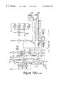
- FIG. 1 depicts a block diagram of a flash memory chip according to the present invention that is capable of simultaneous reading and writing;
- FIG. 2 depicts a block diagram of the flash memory chip of FIG. 1 showing the implementation of the Array Vt test mode.
- FIG. 3 depicts a schematic diagram of test logic circuits for use with the flash memory chip of FIG. 2 .
- FIG. 4 depicts a schematic diagram of a high voltage detect circuit for use with the flash memory chip of FIG. 2 .
- FIG. 5 depicts a schematic diagram of a hardware reset circuit for use with the flash memory chip of FIG. 2 .
- FIG. 6 depicts a schematic diagram of a test mode power circuit for use with the flash memory chip of FIG. 2 .
- FIG. 7 depicts a schematic diagram of a lower bank timing circuit for use with the flash memory chip of FIG. 2 .
- FIG. 8 depicts a schematic diagram of an upper bank timing circuit for use with the flash memory chip of FIG. 2 .
- FIG. 9 depicts a schematic diagram of an output enable test logic circuit for use with the flash memory chip of FIG. 2 .
- FIG. 10 depicts a schematic diagram of a chip enable buffer circuit for use with the flash memory chip of FIG. 2 .
- FIG. 11 depicts a schematic diagram of an output buffer enabling circuit for use with the flash memory chip of FIG. 2 .
- FIG. 12 depicts a schematic diagram of an output buffer control circuit for use with the flash memory chip of FIG. 2 .
- FIG. 13 depicts a schematic diagram of a read/busy input circuit for use with the flash memory chip of FIG. 2 .
- FIG. 14 depicts a schematic diagram of a lower erase select Vt circuit for use with the flash memory chip of FIG. 2 .
- FIG. 15 depicts a schematic diagram of upper erase select Vt circuit for use with the flash memory chip of FIG. 2 .
- FIG. 16 depicts a schematic diagram of a power selection circuit for use with the flash memory chip of FIG. 2 .
- FIG. 17 depicts a schematic diagram of a word line driver circuit for use with the flash memory chip of FIG. 2 .
- FIG. 18 depicts a schematic diagram of an upper and lower bank sense pre-amplifier circuits for use with the flash memory chip of FIG. 2 .
- FIG. 19 depicts a schematic diagram of an upper bank final stage amplifier for use with the flash memory chip of FIG. 2 .
- FIG. 20 depicts a schematic diagram of a lower bank final stage amplifier for use with the flash memory chip of FIG. 2 .
- FIG. 21 depicts a schematic diagram of a high byte output multiplexer for use with the flash memory chip of FIG. 2 .
- FIG. 22 depicts a schematic diagram of a low byte output multiplexer for use with the flash memory chip of FIG. 2 .
- FIG. 23 depicts a schematic diagram of an output buffer circuit for use with the flash memory chip of FIG. 2 .
- FIG. 24 depicts a schematic diagram of an output buffer driver circuit for use with the flash memory chip of FIG. 2 .
- FIG. 25 depicts a schematic diagram of lower and upper bank reference sense pre-amplifier circuits for use with the flash memory chip of FIG. 2 .
- FIG. 26 depicts a schematic diagram of a reference signal path for use with the flash memory chip of FIG. 2 .
- FIG. 27 depicts a schematic diagram of a reference array for use with the flash memory chip of FIG. 2 .
- FIG. 28 depicts a schematic diagram of a reference array multiplexer circuit for use with the flash memory chip of FIG. 2 .
- FIG. 1 there is schematically shown a flash memory device 100 according to the present invention that provides for reading while simultaneously undergoing a program or erase operation.
- the memory device 100 according to the present invention may include one or more components of the memory devices disclosed in U.S. Pat. No. 5,867,430 entitled “BANK ARCHITECTURE FOR A NON-VOLATILE MEMORY ENABLING SIMULTANEOUS READING AND WRITING,” to Chen et al and U.S. Pat. No.
- the memory device 100 may also include one or more components of such exemplary flash memory devices capable of simultaneous read and write operation as the Am29DL162C and Am29DL163C 16 megabit (“Mb”) flash memory chips and the Am29DL322C and Am29DL323C 32 Mb flash memory chips manufactured by Advanced Micro Devices, Inc. located in Sunnyvale, Calif.
- Mb Am29DL162C and Am29DL163C 16 megabit
- the available data storage space can be structured to store data and boot code in one bank and control code in another bank.
- the control code which can contain command sequences which tell one bank, for example, bank 196 , to program/erase data sectors, can reside as executable code in the alternate bank, for example bank 194 .
- the system can continue to execute code from the alternate bank to manage other system operations.
- the CPU can also execute code from the first bank while the alternate bank undergoes a program/erase. There is no bank switching latency and no need to suspend the program/erase operation to perform the read. This minimizes the CPU's read/write cycle time, maximizes data throughput and reduces overall system cost by eliminating the need for additional hardware. It will be appreciated that while the exemplary devices have two banks of memory cells, devices with more than two banks are contemplated.
- the memory device 100 includes a 21 bit address input 102 , a 16 bit data input/output (“DATA”) 192 , power inputs (not shown in FIG. 1) and control inputs (not shown in FIG. 1 ).
- DATA data input/output
- the control inputs include Chip Enable, Output Enable, and Write Enable. The Chip Enable signal activates the chip's control logic and input/output buffers.
- Chip Enable When Chip Enable is not asserted, the memory device operates in standby mode. Output Enable is used to gate the outputs of the device through I/O buffers during read cycles. Write Enable is used to enable the write functions of the memory device. In one embodiment, all of the components of FIG. 1 are contained on a single integrated circuit chip. Note that address and control inputs for the exemplary flash memory chips are dependent on memory density and interface implementations. It will be appreciated that the disclosed embodiments can work with higher memory densities and alternate interface implementations with their accompanying alternate address and control input configurations.
- the memory device 100 further includes address buffer 104 , address multiplexers 106 and 108 , address sequencer 110 , X logical address decoders 112 and 118 , Y logical address decoders 114 and 120 , memory array Banks 0 and 1 denoted as 194 and 196 respectively, Dpump 160 , data multiplexers 170 and 172 , read sense amplifiers 174 , verify sense amplifiers 176 , negative pump 190 , output multiplexer 182 , state machine and control logic 122 , input/output buffers 180 , VPPIG Pump 142 , booster 0 denoted as 132 , VPXGG Pump 134 , booster 1 denoted as 136 and power multiplexers 130 , 138 , 140 and 144 .
- address buffer 104 address multiplexers 106 and 108 , address sequencer 110 , X logical address decoders 112 and 118 , Y logical address decoders 114 and 120 , memory array
- the address input 102 is received by the address buffer 104 , which sends the address to the address multiplexer 106 for bank 194 and the address multiplexer 108 for bank 196 .
- the address sequencer 110 is controlled by the state machine and control logic 122 . In one embodiment, the address sequencer 110 is part of the state machine and control logic 122 .
- the output of the address sequencer 110 is an address which is sent to both multiplexer 106 and multiplexer 108 .
- the address sequencer 110 is used to generate sequential addresses during an erase sequence.
- the output of the multiplexer 106 upper address UA, is communicated to the X address decoder 112 and the Y address decoder 114 .
- the output of the multiplexer 108 is sent to the X address decoder 118 and the Y address decoder 120 .
- the multiplexer 106 chooses between the address from the buffer 104 and the address from the address sequencer 110 in response to a control signal B 0 _sel.
- the multiplexer 108 chooses between the address from the address buffer 104 and the address from address sequencer 110 based on a control signal B 1 _SEL.
- the selection signals B 0 _SEL and B 1 _SEL are generated by the state machine and control logic 122 .
- Bank 194 and bank 196 are arrays (or sets) of flash memory cells (operation of these individual flash memory cells is discussed in more detail below).
- the banks 194 , 196 are organized by words and then by sectors and can either be byte or word addressable. It will be appreciated by those skilled in the art that other types of non-volatile memory are also within the scope of the present invention.
- the address decode logic for bank 194 includes the X address decoder 112 and the Y address decoder 114 .
- the X address decoder 112 includes a word line decoder and sector decoder.
- the word line decoder receives address bits UA[ 6 : 14 ] and the sector decoder receives address bits UA[ 15 : 20 ].
- the Y address decoder 114 includes a bit line decoder and Y bit line gating. The bit line decoder receives address bits UA[ 0 : 5 ].
- the address decode logic for bank 196 includes the X address decoder 118 and the Y address decoder 120 .
- the X address decoder 118 includes a word line decoder and a sector decoder.
- the word decoder receives address bits LA[ 6 : 14 ] and the sector decoder receives address bits LA[ 15 : 20 ].
- the Y address decoder 120 includes a bit line decoder and Y bit line gating.
- the bit line decoder receives address bits LA[ 0 : 5 ].
- the address buffer 104 includes a latch to store the address being decoded.
- the latch can be part of the decoders 112 , 114 , 118 , 120 .
- FIG. 1 further shows a multiplexer 130 with three inputs: booster zero 132 , VPXGG pump 134 and Vcc.
- the VPXGG pump 134 is a positive power supply for generating and supplying a regulated positive potential to the control gate of selected flash memory cells via the word lines.
- Many different voltage pumps known in the art are suitable for use in the present invention.
- a more detailed explanation of one technology which can be included in VPXGG pump 134 can be found in U.S. Pat. No. 5,291,446, “VPP POWER SUPPLY HAVING A REGULATOR CIRCUIT FOR CONTROLLING A REGULATED POSITIVE POTENTIAL” to Van Buskirk et al, the entire contents of which are incorporated herein by reference.
- Booster 132 is used to boost the word line during reads.
- the multiplexer 130 receives a selection signal 197 from state machine and control logic 122 and chooses one of its three inputs to send to the word lines of bank 194 via the X address decoder 112 .
- the output of the multiplexer 130 is labeled as VPXG 0 .
- FIG. 1 is drawn to show the three inputs 132 , 134 and Vcc connected to a multiplexer in order to simplify the disclosure.
- a more detailed description of one exemplary implementation can be found in U.S. Pat. No. 5,708,387, “FAST 3STATE BOOSTER CIRCUIT”, to Cleveland et al, the entire contents of which are incorporated herein by reference.
- Many booster circuits and selection circuits known in the art are suitable for use in the present invention.
- FIG. 1 also includes another multiplexer 138 having three inputs: booster one denoted as 136 , VPXGG pump 134 and Vcc.
- Booster 136 is similar to, booster 132 .
- the multiplexer 138 operates in a similar fashion to multiplexer 130 , and receives its selection signal 198 from the state machine and control logic 122 .
- the output of multiplexer 138 is VPXG 1 which is sent to the word lines of bank 196 via the X address decoder 118 .
- the purpose of the multiplexers 130 and 138 is to switch between the three power lines depending on the operation being performed on the particular bank of memory cells.
- the VPPIG pump 142 is a high voltage pump used to pass high voltage to the drain of the memory cells.
- the output of the VPPIG pump 142 is sent to multiplexer 140 and multiplexer 144 . Both multiplexers also have Vcc as an input. Multiplexers 140 and 144 switch between inputs based on signals 195 and 199 from the state machine and control logic 122 .
- the output of multiplexer 140 is VPPI 0 and the output of multiplexer 144 is VPPI 1 .
- VPPI 1 and VPPI 0 are connected to Vcc.
- VPPI 0 is connected to the gate of an N-channel transistor 152 .
- VPPI 1 is connected to the gate of an N-channel transistor 154 .
- the source of transistor 152 is connected to Y address decoder 114 , multiplexer 170 and multiplexer 172 .
- the drain of transistor 152 is connected to the Dpump 160 and the drain of transistor 154 .
- the Dpump 160 is a drain power supply.
- Various drain power supplies known in the art, can be used for the present invention.
- One exemplary drain pump is disclosed in U.S. Pat. No. 5,263,000, “DRAIN POWER SUPPLY”, to Van Buskirk, et al., the entire contents of which are incorporated herein by reference.
- the source of transistor 154 is connected to multiplexer 170 and multiplexer 172 .
- the source of transistor 154 is also connected to Y address decoder 120 for purposes of accessing the bit lines in bank 196 .
- the connections to multiplexers 170 and 172 provide a path for reading data from bank 194 and bank 196 .
- Multiplexer 170 uses the signal RSA_SEL from the state machine and control logic 122 to selectively choose one of the two input signals to communicate to the read sense amplifiers 174 .
- Multiplexer 172 uses the selection signal VSA_SEL from the state machine and control logic 122 in order to selectively communicate one of its two input signals to the verify sense amplifiers 176 .
- the two transistors ( 152 and 154 ) and the two multiplexers ( 170 and 172 ), are used to selectively pass voltages to the drains of selected cells in bank 194 or bank 196 and to selectively read data from either bank 194 or bank 196 .
- the implementation of multiplexers 170 and 172 is illustrative only. Some of the implementation details are not shown in FIG. 1 .
- In the memory device 100 there are actually two sets of sense amplifiers, one set for each bank 194 , 196 .
- Data from either bank 194 or bank 196 can be communicated to either the read sense amplifiers 174 or the verify sense amplifiers 176 . Both sense amplifiers are in communication with the state machine and control logic 122 . While data from bank 194 is communicated to the read sense amplifiers 174 , data from bank 196 can be communicated to the verify sense amplifiers 176 . While data from bank 194 is communicated to the verify sense amplifiers 176 , data from bank 196 can be communicated to the read sense amplifiers 174 . The output of the verify sense amplifiers 176 is sent to the state machine and control logic 122 , which is used to verify that a particular byte has been programmed or erased.
- the preferred implementation of the read sense amplifiers 174 provides two sets of sense amplifiers, one for each bank 194 , 196 . Only the sense amplifiers for the bank 194 or 196 undergoing a read operation are active during the read operation.
- the verify sense amplifiers 176 of the memory device 100 also have two sets of verify amplifiers, one for each bank.
- Data from the read sense amplifiers 174 is sent to multiplexer 182 .
- a second input of the multiplexer 182 includes device 100 status information from the state machine and control logic 122 such as whether or not a program or erase is in progress.
- the selection signal for multiplexer 182 is provided by the state machine and control logic 122 .
- I/O buffers 180 are used to pass data out and receive data into memory device 100 . While a read is being performed on one of the banks, multiplexer 182 will communicate output data from read sense amplifiers 174 to I/O buffers 180 . During an erase of program sequence, multiplexer 182 will communicate status information to I/O buffers 180 so that an outside processor can poll the memory device 100 for the status in regard to the erase or program.
- the memory device 100 also includes a negative pump 190 that is used to generate a relatively high negative voltage to the control gates of selected memory cells via the word lines of either bank 194 or bank 196 , as selected by the state machine and control logic 122 .
- the negative pump 190 is in communication with the X address decoders 112 and 118 .
- One example of a negative pump can be found in U.S. Pat. No. 5,612,921, “LOW SUPPLY VOLTAGE NEGATIVE CHARGE PUMP”, to Chang et al, the entire contents of which are incorporated herein by reference.
- the state machine and control logic 122 provides the control for read, program and erase operations. Many of the selection lines used to select between bank 194 and bank 196 are controlled by the state machine and control logic 122 . Alternatively, the output from the X and Y address decoders 112 , 114 , 118 , 120 can be used to select between banks of memory cells.
- the memory device 100 is programmed using an embedded programming sequence and is erased using an embedded erase sequence.
- the embedded sequences allow a processor to initiate a program or erase sequence and perform other tasks while the program and erase sequences are being carried out.
- the embedded program and erase sequences are controlled by the state machine and control logic 122 , which uses a command register to manage the commencement of either sequence.
- the erase and programming operations are only accessed via the command register which controls an internal state machine that manages device operations. Commands are written to the command register via the data inputs 192 to the memory device 100 .
- the state machine and control logic 122 would cause multiplexer 108 to select the address from buffer 104 for communication to decoders 118 and 120 . Further, the state machine and control logic 122 would store the data byte to be programmed from the I/O buffers 180 for verification when the programming completes. The output of bank 196 would be sent to the verify sense amplifiers 176 via multiplexer 172 for comparison with the stored input data.
- the state machine and control logic 122 instructs multiplexer 106 to select the address from the buffer 104 for communication to the X and Y address decoders 112 and 114 .
- the output of bank 194 would be sent to the read sense amplifiers 174 via multiplexer 170 .
- the output of the read sense amplifiers 174 would be sent, via multiplexer 182 to the I/O buffers 180 and then to the data bus 192 .
- the state machine and control logic 122 would cause multiplexer 106 to select the addresses from the address sequencer 110 .
- the address sequencer 110 would be used to cycle through all the bytes in a particular sector to make sure that each byte is preprogrammed. The sector is subsequently bulk erased. After erasure, the address sequencer 110 would be used to generate addresses to verify each byte of this erased sector. While bank 194 is being erased and multiplexer 106 is selecting an address from the address sequencer 110 , a read operation can be carried out in bank 196 by using multiplexer 108 to select the address from the buffer 104 rather than an address from address sequencer 110 .
- each bank has two input address paths and two output data paths that can be multiplexed so that either bank can be read from while the other bank is simultaneously being written to.
- each memory cell within the banks 194 or 196 , includes a nor-type floating gate transistor.
- the exemplary transistor has three connections called the source, drain and control gate.
- the control gates of the memory cells are connected to the word lines of the array which are used to address the data stored in the array.
- the sources are selectively connected to ground (for a read operation) depending on which bits are to be read.
- the drains are connected to the bit lines which are used to sense/read the stored data out of the array.
- the source input of the memory cell transistor is connected to a high positive voltage
- the drain/bit line is left to float
- the control gate/word line is connected to a relatively high negative voltage supplied by the negative pump 190 .
- An exemplary high positive voltage applied to the source during an erase is approximately 5 volts and an exemplary high negative voltage applied to the control gate/word line by the negative pump 190 is approximately minus 9 volts although other voltages and input combinations can be used. Based on this input configuration, any charge stored on the floating gate of the memory cell transistor will discharge by flowing out to the source due to Fowler-Nordheim Tunneling.
- the source input of the memory cell transistor is connected to ground, the drain/bit line is connected to a high positive voltage provided by the VPPIG Dpump drain power supply 142 and the control gate/word line is connected to a high voltage provided by the VPXGG pump positive power supply 134 .
- An exemplary high voltage applied to the drain by the VPPIG 142 is approximately 5 Volts while an exemplary high voltage applied to the control gate by the VPXGG 134 pump is approximately 9 Volts. It will be appreciated by those skilled in the art that other voltage and input combinations can also be used. Based on this input configuration, charge will flow by hot electron transfer to the floating gate of the memory cell transistor and accumulate there.
- the source is connected to ground (also referred to as Vss) and the control gate/word line are connected to the booster power supplies 132 , 136 .
- the bit lines Prior to selecting the transistors for a read, the bit lines are charged up via the Dpump 160 . When the cells turn on (if erased), they will connect their respective bit line to ground, grounding out the bit line. The current value of the memory cell is then sensed from the drain/bit line connection.
- the booster power supplies 132 , 136 are used to boost the word lines of bank 194 or bank 196 during a read operation.
- An exemplary Vcc supply voltage is 3.0 Volts although other supply voltages are known in the art.
- An exemplary booster voltage is 5.0 Volts, although the use of the other voltages on the control gate for read operations is possible. If there is charge stored on the floating gate, i.e. the memory cell has been programmed, the flow of current from the drain to the source (ground) will be inhibited and the memory cell will read as a logical “0”.
- This logic 122 controls the multiplexers 130 , 138 , 140 , 144 that place the proper voltages from the various power supplies 132 , 134 , 136 , 142 and Vcc on the memory cell inputs depending on the desired function.
- the flash memory device 100 preferably implements a sliding bank architecture. This architecture allows the simplified design and manufacture of simultaneous flash memory devices with varied bank partition sizes. To alter the bank sizes, only a single metal layer of the chip needs to be altered. For a more detailed discussion of the sliding bank architecture, refer to co-pending and commonly assigned U.S. patent application Ser. No.
- the flash memory device 100 has a capacity of 16 Mb
- partitions where bank 194 has a capacity of 2 or 4 Mb and bank 196 has a capacity of 14 or 12 Mb respectively can be used. This has the advantages that many different configurations of the flash memory device 100 can share much of the same basic design, process and manufacturing expense.
- the memory device 100 preferably provides several internal test features which can be used to ensure that the device 100 is fully functional. In addition, results from internal testing can preferably be used to verify and optimize the fabrication process for other devices 100 .
- One aspect of internal testing and subsequent optimization involves the memory banks 194 , 196 .
- the memory banks 194 , 196 are preferably implemented as arrays of flash memory cells.
- Each cell includes a flash memory transistor which stores a data bit.
- charge stored on the floating gate prevents the transistor from turning on by inhibiting current flow from the source to the drain when a voltage is placed on the gate. In this case, the data bit will read as a logical 0.
- the flash memory transistor is erased, the lack of charge on the floating gate will allow a voltage placed on the gate of the transistor to turn on the transistor, and current will flow from the source to the drain. In this case, the cell will read as a logical 1.
- Vt The voltage required to be placed on the gate input in order to turn on the erased flash memory transistor must exceed a threshold voltage, also referred to as Vt.
- This turn on voltage is actually the voltage potential between the gate input and the source input, also referred to as Vgs. If Vgs is greater than Vt, the transistor will turn on. If Vgs is less than Vt, the transistor will not turn on.
- Vt a flash memory cell in the erased state has Vt of approximately 2-2.5 Volts. Flash memory transistors which are programmed also have a Vt but it is much higher than that of an erased cell. For a cell in the programmed state, the Vt is approximately 4-5 Volts.
- an Array Vt test mode is provided.
- the memory device 100 with a storage capacity of 32 Mb has 32 million flash memory transistors in its memory banks 194 , 196 . It is desirable that all of the transistors have the same Vt value, however process variations and defects in the manufacturing of the device 100 will result in the various flash memory transistors of the memory banks 194 , 196 having different Vt values. Deviations in the Vt across this many transistors can greatly affect the device's 100 operation. It is, therefore, important in optimizing the fabrication process of the device 100 to know the distribution of the different Vt values across the entire memory array of finished devices 100 .
- the information can be used to adjust the fabrication process for a more even and predictable Vt across the array. Further, where the Vt variation is not too large across the array, the manufactured devices 100 may be able to be salvaged despite the Vt variation by, for example, re-erasing the arrays of the devices 100 .
- the testing for the distribution of Vt across the array can also detect other problems. When the transistors of the memory array are under stress, from frequent reading, programming or erasing, the floating gates of some of the transistors can actually gain charge. This will result in an increase in the Vt. If the amount of charge gained on the gate gets too excessive, the transistor will not be able to be turned on during a normal read operation. Determination of the Vt of the transistors during the array Vt test mode will detect any charge gain as this will be seen in an increased Vt for the particular cell. It will be appreciated that there are other problems which can be detected by knowing the Vt distribution.
- an operator or alternatively an automated test machine, is able to test each flash memory transistor and determine its Vt. This is done by placing the device 100 in an Array Vt test mode which allows the operator to place external voltages directly on the gate input of a particular flash memory transistor and vary that voltage until the transistor turns on. For the memory device 100 , this testing will be performed on each generation and even each lot of manufactured devices 100 to establish uniformity and locate any problems in the fabrication process.
- the Array Vt test mode is provided by the device 100 itself utilizing internal logic circuits incorporated into the design of the device 100 .
- the voltage is placed on the gate through an external pin of the device 100 which is routed directly into the flash memory banks 194 , 196 during this test mode.
- the flash memory transistor to be tested is selected by placing its address on the address inputs 102 of the device 100 . If the voltage placed on the gate is greater than the Vt of the selected transistors, the device 100 , will output a logical 1 for the corresponding bit location otherwise it will output a logical 0.
- Each transistor is tested by changing the input address 102 to the device 100 . In this way, each transistor can be accessed and have its Vt tested. Further, the accuracy by which each Vt is determined is entirely within user control as the user chooses which voltages to place on the various transistors' gate inputs as well as the degree in variation of that voltage.
- the voltage source used for testing can be either external to the memory device 100 or integrated internally. Further, the selection of transistors for testing and the application of voltages can be entirely automated either in an external test apparatus or internally to the device 100 .
- the Vt can be determined by starting at a low voltage, 0 volts for example, and increasing the applied gate voltage until the transistor turns on (as described above) or by starting at a high voltage, Vcc (the chip supply voltage, 3 Volts or 2 Volts), for example, and decreasing the voltage until the transistor turns off.
- Vcc the chip supply voltage, 3 Volts or 2 Volts
- the test methodology depends on the type of transistor used in the array. In the memory device 100 , NOR type flash memory transistors are used however, NAND type transistors can also be used.
- the phrase “high logic level” is used to indicate a logical 1 and the phrase “low logic level” is used to indicate a logic level of 0. It will be understood that the signals underlying these representations are actually represented by voltage values. A signal is said to be “asserted” when it has a value which is significant to the logic it is driving. Some signals are asserted when they are at a low logic level (also referred to as “active low” and labeled with a ⁇ overscore (bar) ⁇ over the signal name or a B appended to the end of the signal name) and some signals are asserted when they are at a high logic level (also referred to as “active high”).
- a low logic level also referred to as “active low” and labeled with a ⁇ overscore (bar) ⁇ over the signal name or a B appended to the end of the signal name
- active high also referred to as “active high”.
- FIG. 2 there is shown a block diagram of the memory device 100 of FIG. 1 showing the signals and functional blocks of the Array Vt test mode.
- a number of the components of FIG. 1 have been deleted in FIG. 2 .
- the memory device 100 further includes device inputs for a chip enable input 202 (active low and labeled “ ⁇ overscore (CE) ⁇ ”), an output enable input 204 (active low and labeled “ ⁇ overscore (OE) ⁇ ”), a write enable input 206 (active low and labeled “ ⁇ overscore (WE) ⁇ ”), an accelerate input 208 (labeled “ACC”), a reset input 210 (active low and labeled “ ⁇ overscore (RST) ⁇ ”) and a read/busy input 212 (labeled “R/B”).
- a chip enable input 202 active low and labeled “ ⁇ overscore (CE) ⁇ ”
- an output enable input 204 active low and labeled “ ⁇ overscore (OE) ⁇ ”
- a write enable input 206 active low and labeled “ ⁇ overscore (WE) ⁇ ”
- an accelerate input 208 labeleled “ACC”
- RST reset input 210
- R/B read/busy input
- VH is a high positive voltage greater than approximately 8.5 Volts
- Vax is approximately 7 Volts
- VL is a logical 0 or 0 volts.
- the accelerate input 208 provides a high voltage source for operation of the logic circuits involved in testing. It will be appreciated that the input configuration required to enable the Array Vt test mode is implementation dependent and that other input configurations and implementations may also be used.
- the desired test voltage is placed on the read/busy input 212 and the address of the transistors to be tested is placed on the address inputs 102 of the device 100 .
- the data outputs 192 will read out the results of the test.
- the Array Vt test mode will test eight memory locations at a time and when in word mode, the Array Vt test mode will test 16 memory locations at a time.
- the data outputs 192 will show eight or 16 result bits depending on the mode where a logical 1 means that the input voltage on the read/busy input 212 is greater than Vt and a logical 0 means that the input voltage is less than the Vt.
- the addresses used to address various transistors in the array are either byte addresses or word addresses, thereby testing an entire byte ( 8 ) or word ( 16 ) of transistors at any given time.
- the memory device 100 includes a BYTE input pin (not shown) which, in both normal operation mode and Array Vt test mode, tells the device to operate either byte by byte or word by word. By setting the BYTE input pin to a logical 1, the device 100 is placed in word mode. In word mode, the device accepts a 21 bit address to address 2 bytes (16 bits/transistors) at once and outputs all 16 bits on the data outputs 192 . By setting the BYTE input pin to a logical 0, the device 100 is placed in byte mode and accepts a 22 bit address.
- the disclosed Array Vt mode can work with addresses down to the bit level depending on the implementation of the addressing and read circuits of the device 100 .
- the Array Vt test mode logic utilizes the existing address and read circuits with very little addition dedicated logic and therefore is address resolution independent.
- FIG. 2 further shows other components of the device 100 which enable the Array Vt test mode. See FIGS. 3-29 and their accompanying discussion for more detail on the components shown in FIG. 2 .
- the address inputs 102 of the device 100 are connected with the address buffering and decoding logic 104 , 112 , 114 , 118 , 120 . These logic circuits are coupled with the memory banks 194 , 196 and decode the address to select the particular memory cell transistors within the memory array.
- the memory banks 194 , 196 are then connected to the sense amplifiers 174 , via the signal paths 258 (labeled “qDATABn”) which read the data from the memory cell transistors.
- This logic 104 , 112 , 114 , 118 , 120 is also coupled with the chip enable input 202 through the chip enable input buffer 224 so as to be active when the chip enable input 202 is asserted and shut off when the chip enable input 202 is de-asserted.
- the chip enable input buffer 224 is also under control of the state machine and control logic 122 .
- the state machine and control logic 122 can assert a signal 230 (labeled CEFORCE) which will force the address buffering and decoding logic to turn on even if the chip enable input 202 is unasserted.
- This logic 104 , 112 , 114 , 118 , 120 is the same logic used in the normal read operation of the device 100 .
- the sense amplifiers 174 further include a pre-amplifier stage 214 (labeled “qCASCODR”) and a final amplifier stage 216 A, 216 B (labeled “qSAMP”) connected with the pre-amplifier stage via the signal paths 260 (labeled “qSAin”). There are preferably a set of 16 sense amplifiers 174 for each bank 194 , 196 in the memory device 100 .
- the sense amplifiers 174 connect to the input/output (“I/O”) multiplexers 182 via the signal paths 262 (labeled “qDISBn”).
- the I/O multiplexers 182 include a high byte multiplexer 218 (labeled “IOXH”) and a low byte multiplexer 220 (labeled “IOXL”).
- multiplexers 218 , 220 are connected to the sense amplifiers 174 for both banks 194 , 196 and separately multiplex between the high byte and the low byte coming from each bank 194 , 196 of the word which is being read from the memory array.
- the I/O multiplexers 182 are connected to the output buffers 180 via the signal paths 264 (labeled “DSOn”) which output the data to the device 100 data outputs 192 .
- the output buffers 180 further include an output buffer 222 (labeled “OBUF”) and an output buffer driver 226 (labeled “OBUFDR”).
- OBUF output buffer 222
- OBUFDR output buffer driver 226
- the output buffer 222 buffers the data to be output and is under the control of the output enable input 204 to control whether data is output from the device 100 or not.
- the output enable input 204 is connected with an output buffer control circuit 228 which controls the output buffer 222 .
- the output buffer control circuit 228 contains control circuits 284 and 286 (labeled “WOBUF” and “BLHE” respectively).
- the output buffer drivers 226 are connected to the output buffers 222 via the signal path 266 (labeled “NUGm”) and are used to drive the output data signal through the physical pins of the device 100 .
- the output buffer control circuit 228 is also connected to the state machine and control logic 122 by the signal 232 (labeled “OEFORCE”). As will be discussed below, the OEFORCE signal 232 allows the state machine and control logic to force the output buffers to turn on despite the value of the output enable input 204 .
- FIG. 2 also shows the word line control circuit 234 connected with memory array (banks 194 , 196 ) and the read/busy input 212 .
- the word line control circuit is also connected to the state machine and control logic 122 via the control signal 236 (labeled “ATB”).
- the word line control circuit 234 includes a lower erase select Vt circuit 288 (labeled “LERSELVT”), an upper erase select Vt circuit 290 (labeled “UERSELVT”), word line power selection circuits 292 (labeled “VPX”) and word line drivers 294 (labeled “XDECEND”).
- LERSELVT lower erase select Vt circuit 288
- UERSELVT upper erase select Vt circuit 290
- VPX word line power selection circuits
- XDECEND word line drivers
- each memory cell transistor is connected to the Y decoding logic 114 , 120 which further connects them to the sense amplifiers 174 , the gates are connected to the X address decoder 112 , 118 and the sources are grounded.
- the Y address decoder 114 , 120 To activate a particular memory cell transistor, the Y address decoder 114 , 120 must decode the given address into the column in the memory bank 194 , 196 in which the memory cell is located. Note that the memory device 100 is either byte or word addressable so that either an entire byte ( 8 ) of memory cells will be activated at any one time or an entire word ( 16 ) of memory cells will be activated. Once decoded, the Y address decoder 114 , 120 will connect the drain connections of those memory cells to the sense amplifiers 174 .
- the X address decoder 112 , 118 decodes the address into the row and selects the row in which the memory cell transistors are located. The combination of the column and row isolates the selected transistors as determined by the address.
- the X address decoder 112 , 118 includes the word line control circuit 234 .
- the word line control circuit 234 provides the gate voltage to the gates of the selected memory cell transistors for reading or other operations. If the state machine and control logic 122 asserts the ATB control signal 236 , the word line control circuit 234 switches over from the normal gate voltage power supply and provides what ever voltage is on the read/busy input 212 directly to the gates of the selected memory cell transistors.
- the memory device 100 there are preferably 65 word line control circuits, one for each sector of the array.
- the memory device 100 preferably has 65 sectors, 63 64-kilobit sectors, one 64-kilobit sector broken down into eight 8-kilobit boot sectors and one 64-kilobit secured sector.
- FIG. 2 also shows the reference circuits 252 for the memory device 100 .
- the final amplifier stage 216 A, 216 B In order for the sense amplifiers 174 to properly sense the data from the memory array, the final amplifier stage 216 A, 216 B must compare the sensed value with a reference value. The final amplifier stage 216 A, 216 B uses a differential sense amplifier to accomplish this comparison. It will be appreciated that differential sense amplifiers are well known in the art.
- the sense amplifiers 174 are connected with the reference circuits 252 , via the signal path 256 (labeled “qSAREF”), which provide the proper reference value.
- the reference circuits 252 include a reference array 242 , a reference signal path 240 (labeled “RPATH”) and reference sense pre-amplifiers 238 (labeled “qSAREFR”).
- the reference array 242 is connected to the reference signal path 240 via signal paths 270 (labeled “qDATAR”).
- the reference signal path 240 is connected to the reference sense pre-amplif
- the reference sense pre-amplifiers 238 sense the voltage stored on the selected reference transistor cell 244 , 246 and communicate that to the sense amplifiers 174 .
- the reference sense pre-amplifiers are under control of the state machine and control logic 122 via the signal path 250 (labeled “qPDSA”).
- the qPDSA signal 250 powers down the sense amplifiers (turns them off) when it is asserted.
- the reference signal path 240 includes specially isolated signal paths which carry the signals from the reference array 242 to the reference sense pre-amplifiers 238 .
- the reference array 242 further includes a reference read cell 244 , a reference erase cell 246 and a multiplexer 248 .
- the reference read cell 244 and the reference erase cell 246 are specially isolated flash memory transistors.
- the reference erase cell 246 is maintained in an erased state and has pre-set low Vt.
- the reference read cell 244 is pre-set with a larger Vt.
- the multiplexer 248 is under control of the state machine and control logic 122 via the signal path 254 (labeled “SEL_RB( 0 )”).
- the appropriate reference cell 244 , 246 is selected for connection with the reference sense pre-amplifiers 174 via the RPATH signal path 240 .
- the reference erase cell 246 is connected to the reference signal path 240 and used for determining the Vt of the transistors under test by the sense amplifiers 174 .
- the reference erase cell's 246 low Vt allows a more accurate determination of the actual Vt of the transistors undergoing test.
- the read reference cell 244 has a higher Vt because it is used for both, comparing with programmed cells and erased cells under the normal operating voltage. The read reference cell 244 is used to provide a more discriminating capability to the sense amplifiers 174 .
- test logic circuits 270 labeled “TEST_LOGIC”. This logic is a part of the state machine and control logic 122 . It contains the circuits which respond to the memory device 100 inputs and put the device 100 in Array Vt test mode.
- the test logic circuits 270 include a chip enable high voltage detector 302 , a write enable high voltage detector 304 , an array test signal generator 306 , a chip enable override circuit 308 , a test power on signal generator 310 and a test mode signal generator 312 .
- the chip enable high voltage detector 302 is coupled with the chip enable input 202 .
- the write enable high voltage detector 304 is coupled with the write enable input 206 .
- the chip enable high voltage detector 302 and the write enable high voltage detector 304 both contain a high voltage detection circuit (shown in FIG. 4 and discussed in more detail below) which detects when high voltage is placed on their respective input pins 202 , 206 .
- the chip enable high voltage detector 302 asserts the output 314 labeled “CEH” when VH is detected on the chip enable input 202 .
- the write enable high voltage detector 304 asserts the output 316 labeled “WEH” when VH is detected on the write enable input 206 .
- VH is preferably a high positive voltage equal to or greater than 8.5 Volts.
- the array test signal generator 306 generates the AT 318 , ATB 320 , VTA 322 and VTAB 324 test mode signals which are used by other circuits discussed below to switch into test mode.
- the array test signal generator has inputs for the CEH signal 314 , the WEH signal 316 and a HWRESET signal 504 .
- the HWRESET signal 504 is generated by the HWRESET circuit (shown in FIG. 5 and discussed in more detail below).
- CEH 314 , WEH 316 and HWRESET 504 are all logic 1 the NAND gate 326 will be 0.
- the output of the NAND gate 326 is inverted to generate the AT signal 318 and inverted a second time to generate the ATB signal 320 .
- the chip enable override circuit 308 generates the CEFORCE signal 230 to enable the address decoding logic 104 , 112 , 114 , 118 , 120 despite the value of the chip enable input 202 .
- the NOR gate 330 will output a 0 no matter what the value is on the other input.
- the output of the NOR gate 330 is connected with an inverter 332 which is connected with the CEFORCE signal 230 . This will result in a value of 1 being placed on the CEFORCE signal 230 when the VTA signal 322 is a 1.
- the test power on signal generator 310 is responsive to the VTAB signal 324 .
- the VTAB signal 324 connects to a NAND gate 334 .
- the output of the NAND gate connects to a NOR gate 336 .
- the output of the NOR gate 336 connects to another NOR gate 338 .
- the output of the NOR gate 338 is the test power on signal 340 , labeled “VPEON”.
- the VPEON signal goes to the VPPE circuit which is shown in FIG. 6 and described in more detail below.
- NOR gate 338 further has an input for a power on ok signal 342 (labeled “VCCOKB” which is active low).
- This power-on-ok signal 342 comes from the device 100 power circuits (not shown) which indicates that the device 100 is receiving its normal operating voltage Vcc within the proper tolerances. If the power-on-ok signal 342 and the output of the NOR gate 336 are 0 (indicating test mode and Vcc power is within normal tolerances), then the output of the NOR gate 338 , the VPEON signal 340 , will be a 1 telling the test power circuits 276 to provide power for testing.
- the test mode signal generator 312 generates a test mode signal 344 labeled “TESTM”. This signal 344 is used by other read path logic to keep the read path of the device 100 operational in the test mode.
- the generator 312 has an input for the ATB signal 320 . This signal passes through inverter 346 to NOR gate 348 . The output of the NOR gate 348 is the test mode signal 344 (labeled “TESTM”). When the ATB signal 320 is 0, the input to the NOR gate 348 is 1 which forces the output of the NOR, the test mode signal 344 , to 0.
- FIG. 4 there is shown a schematic diagram of the high voltage detect circuit 272 , labeled “HVD”.
- This logic is a part of the state machine and control logic 122 .
- This schematic shows the implementation of the chip enable high voltage detector 314 and the write enable high voltage detector 316 which have the same circuit design.
- This circuit is coupled with the respective input pin (chip enable 202 or write enable 206 ) via the input labeled “INESDR” and detects when VH is placed on the input pin.
- the circuit 272 will output a 1 via the output labeled “INH” and a 0 via the output “INHB” when high voltage is detected.
- VH is preferably a high positive voltage equal to or greater than 8.5 V.
- FIG. 5 there is shown a schematic diagram of the hardware reset circuit 274 , labeled “HWRESET”. This logic is a part of the state machine and control logic 122 .
- This circuit 274 generates the hardware reset signal 504 (labeled “HWRESET”). This signal 504 is used by the test logic circuits 270 (described above) to generate the test mode signals.
- This circuit 504 is coupled with the reset input 210 of the device 100 and outputs a 1 on the HWRBSET signal 504 when the reset input 210 is 0. Note that the reset input 210 is an active low signal.
- FIG. 6 there is shown a schematic diagram of the test mode power circuits 276 , labeled “VPPE”.
- This logic is a part of the state machine and control logic 122 .
- FIG. 7 there is shown a schematic diagram of the upper bank 194 timing circuits 278 , labeled “UTIME”.
- This logic is a part of the state machine and control logic 122 .
- This circuit 278 generates the read timing control signals for the read logic which supports the upper memory bank 194 .
- the UTIME circuits 278 In normal operation, the UTIME circuits 278 generate specifically timed signals to control and optimize the read access time of the device 100 .
- Array Vt mode the UTIME circuits 278 are fixed in a steady state read mode where the normal operation timing is overridden. In this test mode, access time is not an issue.
- the circuits 278 are responsive to ATB signal 320 and the TESTM signal 344 from the test logic 270 .
- the UTIME circuits 278 will force on the sense amplifiers 174 to read and output the data from the array.
- This circuits 278 are cross-coupled with the LTIME circuit 280 which is the circuit that generates the timing signals for the lower memory bank 196 .
- the following signals are inputs to this logic: TESTM 344 (FIG. 3 ), ATB 320 (FIG. 3 ), PDAD 1002 (see FIG. 10 which is described in more detail below), ULT 802 (see FIG. 4 which is described in more detail below) and UBRSEL 718 .
- This circuit outputs the following signals: UEQ 704 (see FIG. 19 ), UKICKB 714 and UPDSA 716 .
- the UBRSEL signal 718 is generated by the address decoding logic 104 , 112 , 114 , 118 , 120 which indicates whether or not the upper bank 194 is selected for a read operation based on the input address.
- the UKICKB signal 714 is used to activate the word line boosters (not shown in the figures) for a normal read operation. In the case of the Array Vt test mode, the word line voltage is supplied externally so the voltage boosters are not used. This signal is an active low signal and is forced to 1 by the UTIME circuits 278 .
- the UPDSA signal 716 is used to power down the upper bank 194 sense amplifiers 174 when the upper bank 194 is not being used.
- FIG. 8 there is shown a schematic diagram of the lower bank 196 timing circuits 280 , labeled “LTIME”.
- This logic is a part of the state machine and control logic 122 .
- This circuit 280 generates the read timing control signals for the read logic which supports the lower memory bank 196 .
- the LTIME circuits 280 In normal operation, the LTIME circuits 280 generate specifically timed signals to control and optimize the read access time of the device 100 .
- the LTIME circuits 280 are fixed in a steady state read mode where the normal operation timing is overridden. In this test mode, access time is not an issue.
- the circuits 280 are responsive to ATB signal 320 and the TESTM signal 344 from the test logic 270 .
- the LTIME circuits 280 will force on the sense amplifiers 174 to read and output the data from the array.
- This circuits 280 are cross-coupled with the LTIME circuit 280 which is the circuit that generates the timing signals for the lower memory bank 196 .
- the following signals are inputs to this logic: TESTM 344 (FIG. 3 ), ATB 320 (FIG. 3 ), PDAD 1002 (see FIG. 10 which is described in more detail below), and LBRSEL 820 .
- This circuit outputs the following signals: ULT 802 , LLT 806 , LEQ 804 (see FIG. 19 ), LKICKB 714 and LPDSA 716 .
- the LBRSEL signal 718 is generated by the address decoding logic 104 , 112 , 114 , 118 , 120 which indicates whether or not the lower bank 196 is selected for a read operation based on the input address.
- the ULT 802 and the LLT 806 signals go to the final amplifier stage 216 A, 216 B of the sense amplifiers 174 (See FIGS. 19 and 20 which are described in more detail below). These signals 802 , 806 control the latching of output data from the memory banks 194 , 196 and are both generated in the LTIME circuits 280 for timing purposes.
- the LKICKB signal 818 is used to activate the word line boosters (not shown in the figures) for a normal read operation.
- the word line voltage is supplied externally so the voltage boosters are not used.
- This signal is an active low signal and is forced to 1 by the LTIME circuits 280 .
- the LPDSA signal 816 is used to power down the lower bank 196 sense amplifiers 174 when the lower bank 196 is not being used.
- FIG. 9 there is shown a schematic diagram of the OEFORCE test logic circuits 282 , labeled “TEST_LOGIC_ 2 ”.
- This circuit is part of the state machine and control logic 122 .
- This circuit has an input for the AT signal 318 from the test logic circuits 270 .
- the CE signal 1004 will be the inverted value of the chip enable input 202 which in the Array Vt test mode, will be 1 making the CE signal 1004 a 0.
- This circuit will generate the OEFORCE signal 232 which is used by the WOBUF circuit 228 (see FIG. 11 which is described in more detail below).
- the OEFORCE signal 232 will override the output enable input 204 and enable the output buffers 180 to output the read data.
- FIG. 10 there is shown a schematic diagram of the chip enable buffer circuits 224 , labeled “CEBUF”.
- This circuit 224 generates the CE signal 1004 and the PDAD signal 1002 .
- This circuit is coupled with the chip enable input 202 and the CEFORCE signal 230 .
- the CEFORCE signal 230 will force the PDAD signal 1002 to 0, overriding the value of the chip enable input 202 .
- This signal 1002 controls the address decoders. When PDAD 1002 is a 0, the address decoders turn on.
- the CE signal 1004 is the inverted value of the chip enable input 202 . In Array Vt test mode, the chip enable input 202 is at VH which is a logic 1 state. This sets the CE signal 1004 to 0.
- FIG. 11 there is shown a schematic diagram of the write output buffer circuit 284 of the output buffer control circuit 228 , labeled “WOBUF”.
- This circuit 284 is coupled with the output enable input 204 , and the OEFORCE signal 232 generated by the TEST_LOGIC_ 2 circuit 282 (see FIG. 9 described above).
- the OEFORCE signal 232 overrides the value of the output enable input 204 and forces the OEB output 1102 to 0.
- the OEB output 1102 goes to the BLHE circuit 286 (see FIG. 12 which is described in more detail below) to generate the output buffer enable signals.
- FIG. 12 there is shown a schematic diagram of the buffer enable circuits 286 of the output buffer control circuit 228 , labeled “BLHE”.
- This circuit 286 generates the buffer enable signals 1202 (labeled “BEq”) which enable the output buffers.
- BEq buffer enable signals
- This circuit is used 16 times for each output buffer 222 .
- This circuit is responsive to the OEB signal 1102 from the WOBUF circuit 284 .
- the BLHE circuit 286 will shut down the unused output buffers 222 .
- FIG. 13 there is shown a schematic diagram of the read/busy input circuit 212 , labeled “RBUSYDR”.
- This circuit 212 connects directly with the read/busy input pin of the device 100 . During normal operation, this pin is an output which shows the status of the device 100 to the user. However, during the Array Vt test mode, this pin is used as an input for the test voltage.
- This circuit 212 implements the bi-directional nature of the read/busy pin.
- the output 1302 (labeled “RDYR”) of the circuit goes to the lower erase select Vt circuit (see FIG. 14 which is described in more detail below) where it is routed ultimately to the word lines of the memory banks 194 , 196 .
- FIG. 14 there is shown a schematic diagram of the lower erase select Vt circuits 288 of the word line control circuit 234 , labeled “LERSELVT”.
- This circuit 234 has inputs for the ATB signal 320 from the test logic circuits 270 (see FIG. 3) and the RDYR signal 1302 from the read/busy input 212 (see FIG. 13 ). If the ATB signal 320 is 0 (which it will be when the device 100 is in array VT mode), the circuit 234 routes the RDYR signal 1302 (which is carrying the input test voltage from the read/busy input pin) to the word line power selection circuits 292 (see FIG.
- This circuit 288 also generates the output signal 1406 (labeled “LERSELVT”) which tells the word line power selection circuits 292 for the lower bank 196 to select the LERSELBVT input 1404 as the power source for the array word lines as opposed to the normal read power supply.
- FIG. 15 there is shown a schematic diagram of the upper erase select Vt circuits 290 of the word line control circuit 234 , labeled “UERSELVT”.
- This circuit 290 has an input for the ATB signal 320 from the test logic circuits 270 (see FIG. 3 ).
- This circuit 290 generates the output signal 1502 (labeled “UERSELVT”) which tells the word line power selection circuits 292 for the upper bank 194 to select the UERSELBVT input 1402 as the power source for the array word lines as opposed to the normal read power supply.
- FIG. 16 there is shown a schematic diagram of the word line power selection circuits 292 of the word line control circuit 234 , labeled “VPX”.
- This circuit 292 is used for each sector in the memory array.
- the memory array is broken down into 65 sectors. 63 of the sectors are normal 64 Kilobit sectors. One of the sectors is actually eight 8 kilobit sectors. The last sectors is secured sector which is a special protected sector.
- the division of sectors between the upper and lower banks 194 , 196 is variable and depends on the sliding bank architecture as described above.
- the circuit 292 has inputs for the qERSELBVT signal 1402 , 1404 , the qERSELVT signals 1406 , 1502 and a selection signal 1602 (labeled “SELn”). Operation of this circuit 292 is detailed in the truth table 1604 which details which combination of inputs will route which power supply to the word lines in the particular sector.
- the qERSELBVT input 1402 , 1404 is routed to the word lines, effectively routing the read/busy pin input test voltage to the memory array transistors via the output signal 1606 (labeled “VPXn”).
- FIG. 17 there is shown a schematic diagram of the word line drivers 294 of the word line control circuit 234 , labeled “XDECEND”.
- This circuit 294 is depicted for 8 word lines. Each word line is for 1 sector, therefore this circuit is used 8 times for 64 sectors plus it is implemented once for a single word line for the 65 th sector.
- This circuit 294 connects to the word lines of memory array and to the address decoding logic 104 , 112 , 114 , 118 , 120 .
- This circuit 294 selects the proper row in the array and provides the voltage supplied by the VPX circuits 292 to the gates of the memory cell transistors within the row.
- This circuit 294 has an input for the VPXn output signal 1606 of the VPX circuit 292 and an output 1702 for the word line (labeled “WLn”).
- FIG. 18 there is shown a schematic diagram of the upper and lower bank sense pre-amplifier 214 circuits, labeled “LCASCODR” 1802 and “UCASCODR” 1804 .
- These circuits 214 pre-amplify the data from the memory array.
- the data from the lower memory bank 196 comes into the LCASCODR 1802 via the input 1806 (labeled LDATABn) and the data from the upper memory bank 194 comes in to the UCASCODR 1804 via the input 1808 (labeled UDATABn).
- the data is then amplified and passed on to the upper and lower final amplifier stages 216 A, 216 B (see FIGS.
- the USAMP 216 A receives the USAin signal 1812 from the UCASCODR 1804 , the ULT signal 802 from the LTIME circuit 280 (see FIG. 8) and the UEQ signal 704 from the UTIME circuit 278 (see FIG. 7 ).
- the ULT signal 802 and the UEQ signal 704 enable the USAMP 216 A to operate.
- the USAMP 216 A is a differential amplifier which compares the input signal, USAin 1812 with a reference signal 2504 from the reference circuits (see FIGS. 25 - 29 ).
- the USAMP 216 A outputs the data from the output 1902 (labeled “UDSIBn”).
- This output 1902 along with the output 2002 from the LSAMP 216 B (see FIG. 20) forms the qDSIBn signal path 262 to the I/O multiplexers 182 .
- This circuit 216 A is designed to gate the LDSIBn output 1902 so that it is only active when the lower bank 196 is being read otherwise a 0 is output.
- the LSAMP 216 B receives the LSAin signal 1812 from the LCASCODR 1802 , the LLT signal 806 from the LTIME circuit 280 (see FIG. 8) and the LEQ signal 808 from the LTIME circuit 280 (see FIG. 8 ).
- the LLT signal 806 and the LEQ signal 808 enable the LSAMP 216 B to operate.
- the LSAMP 216 B is a differential amplifier which compares the input signal, LSAin 1810 with a reference signal 2502 from the reference circuits (see FIGS. 25 - 29 ).
- the LSAMP 216 B outputs the data from the output 2002 (labeled “LDSIBn”). This output 2002 along with the output 1902 from the USAMP 216 A (see FIG. 19) forms the qDSIBn signal path 262 to the I/O multiplexers 182 .
- This circuit 216 B is designed to gate the UDSIBn output 2002 so that it is only active when the upper bank 194 is being read otherwise a 0 is output.
- FIG. 21 there is shown a schematic diagram of the high byte output multiplexer 218 circuits, labeled “IOXH”.
- This circuit 218 is used 8 times for each bit of the high byte of the word that can be output from device 100 .
- the multiplexer 218 has inputs for the high byte (bits 8:15) LDSIBn 1902 and UDSIBn 2002 signals from the LSAMP 216 A and the USAMP 216 B respectively.
- the multiplexing is accomplished with a NAND gate 2102 which effectively passes the active signal through to the output 264 (labeled “DSOn”).
- FIG. 22 there is shown a schematic diagram of the low byte output multiplexer 220 circuits, labeled “IOXL”.
- This circuit 220 is used 8 times for each bit of the low byte of the word that can be output from device 100 .
- the multiplexer 220 has inputs for the low byte (bits 0 : 7 ) LDSIBn 1902 and UDSIBn 2002 signals from the LSAMP 216 A and the USAMP 216 B respectively.
- the multiplexing is accomplished with a NAND gate 2102 which effectively passes the active signal through to the output 264 (labeled “DSOn”).
- FIG. 23 there is shown a schematic diagram of the output buffer 222 circuits, labeled “OBUF”.
- This circuit 222 has an input 2302 for the DSOn signals 264 from the I/O multiplexers (see FIGS. 21 and 22 ).
- the data is buffered and then sent to the output buffer drivers 226 via the output 266 (labeled “NUGm”).
- the output buffer driver 226 receives the data to be output from the output buffer 222 via the NUGm signal paths 266 .
- the output buffer driver 226 couples the output buffer 222 to the output pins 192 and also implements the bi-directional capability of the output pins 192 .
- the reference sense preamplifier circuits 238 include a lower bank reference sense pre-amplifier 2506 (labeled “LSAREFR”) and an upper bank reference sense pre-amplifier 2508 (labeled “USAREFR”). These pre-amplifier circuits are coupled with the reference transistor cells 244 , 246 in the reference array 242 by the reference signal paths 240 . They pre-amplify the reference values and send them to the final amplifier stage 216 A, 216 B where they are used to sense the data from the memory array.
- the LSAREFR circuit 2506 is coupled with the LSAMP 216 B via the LSAref signal path 2502 .
- the USAREFR circuit 2508 is coupled with the USAMP 216 A via the USAref signal path 2504 . They are coupled with the reference signal paths 240 via the LDATABRR 2606 and UDATABRR 2608 signal paths which together form the qDATABRR signal path 268 between the reference signal paths 240 and the reference sense pre-amplifiers 238 .
- the reference signal path circuits 240 include an upper circuit 2602 for interconnecting the reference array 242 with the upper bank 194 reference sense amplifier 2508 and a lower circuit 2604 for interconnecting the reference array 242 with the lower bank 196 reference sense amplifier 2506 .
- the inputs to the circuits 240 are UDATAR 2802 and LDATAR 2804 which come from the reference array multiplexer 248 and together form the qDATAR signal path 270 .
- the outputs of the reference signal path circuits are LDATABRR 2606 and UDATABRR 2608 which together form the signal path qDATABRR 268 .
- the reference array 242 contains four reference transistors, a erase reference cell 2702 (labeled “RB( 0 )”), a read reference cell 2704 (labeled “RB( 2 )”), a program reference cell 2706 (labeled “RB( 3 )”) and an auto-program-disturb-after-erase-verify reference cell 2708 (labeled “RB( 4 )”).
- Each reference cell is used for different functions of the device 100 .
- the erase reference cell is used.
- the reference cells are in a large array of dummy cells which are used to isolate the reference cells from the remainder of the logic of the device 100 .
- FIG. 28 there is shown a schematic diagram of the reference array multiplexer 248 circuits, labeled “REFPBL”.
- This circuit 28 determines which reference cell 2702 , 2704 , 2706 , 2708 is used at any given time.
- This circuit 248 has an input for the ATB signal 320 from the test logic circuits 270 (see FIG. 3 ). When the ATB signal is a 0, NAND gate 2806 will turn on and subsequently turn on transistors 2808 and 2810 which connect the erase reference cell RB( 0 ) to the UDATAR 2802 and LDATAR 2804 outputs which together form the qDATAR signal path 270 to the reference signal path circuits 240 .
- the implementation of the disclosed embodiments shares much of the same logic as the normal read operating mode of the memory device 100 . This saves design time and cost because separate circuitry specifically for the Array Vt test mode does not have to be implemented.
- suitable transistor sizes specifying channel width to length ratios (measured in micrometers or microns) for the transistors which make up the depicted circuits have been omitted from the figures. It will be appreciated that suitable ratios may be chosen depending on the design requirements and the capabilities and limitations of the particular integrated circuit fabrication process used for implementation of the circuit as well as the performance requirements of the specific embodiment.
Abstract
Description
Claims (30)
Priority Applications (1)
| Application Number | Priority Date | Filing Date | Title |
|---|---|---|---|
| US09/421,470 US6550028B1 (en) | 1999-10-19 | 1999-10-19 | Array VT mode implementation for a simultaneous operation flash memory device |
Applications Claiming Priority (1)
| Application Number | Priority Date | Filing Date | Title |
|---|---|---|---|
| US09/421,470 US6550028B1 (en) | 1999-10-19 | 1999-10-19 | Array VT mode implementation for a simultaneous operation flash memory device |
Publications (1)
| Publication Number | Publication Date |
|---|---|
| US6550028B1 true US6550028B1 (en) | 2003-04-15 |
Family
ID=23670656
Family Applications (1)
| Application Number | Title | Priority Date | Filing Date |
|---|---|---|---|
| US09/421,470 Expired - Fee Related US6550028B1 (en) | 1999-10-19 | 1999-10-19 | Array VT mode implementation for a simultaneous operation flash memory device |
Country Status (1)
| Country | Link |
|---|---|
| US (1) | US6550028B1 (en) |
Cited By (9)
| Publication number | Priority date | Publication date | Assignee | Title |
|---|---|---|---|---|
| US20020178414A1 (en) * | 2001-04-09 | 2002-11-28 | Micron Technology, Inc. | Synchronous flash memory with test code input |
| US6973003B1 (en) | 2003-10-01 | 2005-12-06 | Advanced Micro Devices, Inc. | Memory device and method |
| FR2871281A1 (en) * | 2004-04-01 | 2005-12-09 | Atmel Corp | METHOD AND DEVICE FOR FEEDING DUAL POWER FOR A NON-VOLATILE MEMORY ON BOARD |
| EP1747559A2 (en) * | 2004-04-01 | 2007-01-31 | Atmel Corporation | Method and apparatus for a dual power supply to embedded non-volatile memory |
| US20080062767A1 (en) * | 2006-09-13 | 2008-03-13 | Stmicroelectronics S.R.L. | Method of fixing a read evaluation time or the difference between a read charge voltage and a read discriminating voltage in a non-volatile nand type memory device |
| US20090207673A1 (en) * | 2008-02-14 | 2009-08-20 | Hynix Semiconductor Inc. | Semiconductor integrated circuit with multi test |
| US20130064017A1 (en) * | 2010-12-28 | 2013-03-14 | Taiwan Semiconductor Manufacturing Co., Ltd. | Concurrent operation of plural flash memories |
| CN113409839A (en) * | 2021-06-28 | 2021-09-17 | 芯天下技术股份有限公司 | Storage unit threshold voltage reading method and device, electronic equipment and storage medium |
| US11474890B2 (en) * | 2019-07-02 | 2022-10-18 | SK Hynix Inc. | Memory system and method of operating memory system |
Citations (29)
| Publication number | Priority date | Publication date | Assignee | Title |
|---|---|---|---|---|
| US5142496A (en) * | 1991-06-03 | 1992-08-25 | Advanced Micro Devices, Inc. | Method for measuring VT 's less than zero without applying negative voltages |
| US5153853A (en) * | 1990-09-20 | 1992-10-06 | Sharp Kabushiki Kaisha | Method and apparatus for measuring EEPROM threshold voltages in a nonvolatile DRAM memory device |
| US5233562A (en) * | 1991-12-30 | 1993-08-03 | Intel Corporation | Methods of repairing field-effect memory cells in an electrically erasable and electrically programmable memory device |
| US5263000A (en) | 1992-10-22 | 1993-11-16 | Advanced Micro Devices, Inc. | Drain power supply |
| US5291446A (en) | 1992-10-22 | 1994-03-01 | Advanced Micro Devices, Inc. | VPP power supply having a regulator circuit for controlling a regulated positive potential |
| US5357462A (en) * | 1991-09-24 | 1994-10-18 | Kabushiki Kaisha Toshiba | Electrically erasable and programmable non-volatile semiconductor memory with automatic write-verify controller |
| US5386422A (en) * | 1991-03-12 | 1995-01-31 | Kabushiki Kaisha Toshiba | Electrically erasable and programmable non-volatile memory system with write-verify controller using two reference levels |
| US5481494A (en) * | 1994-12-22 | 1996-01-02 | Advanced Micro Devices, Inc. | Method for tightening VT distribution of 5 volt-only flash EEPROMS |
| US5708387A (en) | 1995-11-17 | 1998-01-13 | Advanced Micro Devices, Inc. | Fast 3-state booster-circuit |
| US5748546A (en) * | 1994-06-02 | 1998-05-05 | Intel Corporation | Sensing scheme for flash memory with multilevel cells |
| US5790459A (en) * | 1995-08-04 | 1998-08-04 | Micron Quantum Devices, Inc. | Memory circuit for performing threshold voltage tests on cells of a memory array |
| US5841696A (en) | 1997-03-05 | 1998-11-24 | Advanced Micro Devices, Inc. | Non-volatile memory enabling simultaneous reading and writing by time multiplexing a decode path |
| US5847998A (en) | 1996-12-20 | 1998-12-08 | Advanced Micro Devices, Inc. | Non-volatile memory array that enables simultaneous read and write operations |
| US5867430A (en) | 1996-12-20 | 1999-02-02 | Advanced Micro Devices Inc | Bank architecture for a non-volatile memory enabling simultaneous reading and writing |
| US5909398A (en) * | 1994-08-19 | 1999-06-01 | Kabushiki Kaisha Toshiba | Semiconductor memory device and high-voltage switching circuit |
| US5959929A (en) * | 1997-12-29 | 1999-09-28 | Micron Technology, Inc. | Method for writing to multiple banks of a memory device |
| US5963500A (en) * | 1997-02-26 | 1999-10-05 | Kabushiki Kaisha Toshiba | Semiconductor memory device |
| US5986944A (en) * | 1997-02-14 | 1999-11-16 | Micron Technology, Inc. | Method and apparatus using a data read latch circuit in a semiconductor device |
| US5996106A (en) * | 1997-02-04 | 1999-11-30 | Micron Technology, Inc. | Multi bank test mode for memory devices |
| US6005803A (en) | 1998-09-23 | 1999-12-21 | Advanced Micro Devices, Inc. | Memory address decoding circuit for a simultaneous operation flash memory device with a flexible bank partition architecture |
| US6011721A (en) * | 1998-08-12 | 2000-01-04 | Advanced Micro Devices | Method for sensing state of erasure of a flash electrically erasable programmable read-only memory (EEPROM) |
| US6016270A (en) | 1998-03-06 | 2000-01-18 | Alliance Semiconductor Corporation | Flash memory architecture that utilizes a time-shared address bus scheme and separate memory cell access paths for simultaneous read/write operations |
| US6026465A (en) * | 1994-06-03 | 2000-02-15 | Intel Corporation | Flash memory including a mode register for indicating synchronous or asynchronous mode of operation |
| US6052310A (en) * | 1998-08-12 | 2000-04-18 | Advanced Micro Devices | Method for tightening erase threshold voltage distribution in flash electrically erasable programmable read-only memory (EEPROM) |
| US6128219A (en) * | 1999-10-27 | 2000-10-03 | Stmicroelectronics, S.R.L. | Nonvolatile memory test structure and nonvolatile memory reliability test method |
| US6172909B1 (en) * | 1999-08-09 | 2001-01-09 | Advanced Micro Devices, Inc. | Ramped gate technique for soft programming to tighten the Vt distribution |
| US6324108B1 (en) * | 2000-02-29 | 2001-11-27 | Advanced Micro Devices, Inc. | Application of external voltage during array VT testing |
| US6381670B1 (en) * | 1997-01-07 | 2002-04-30 | Aplus Flash Technology, Inc. | Flash memory array having maximum and minimum threshold voltage detection for eliminating over-erasure problem and enhancing write operation |
| US6418070B1 (en) * | 1999-09-02 | 2002-07-09 | Micron Technology, Inc. | Memory device tester and method for testing reduced power states |
-
1999
- 1999-10-19 US US09/421,470 patent/US6550028B1/en not_active Expired - Fee Related
Patent Citations (32)
| Publication number | Priority date | Publication date | Assignee | Title |
|---|---|---|---|---|
| US5153853A (en) * | 1990-09-20 | 1992-10-06 | Sharp Kabushiki Kaisha | Method and apparatus for measuring EEPROM threshold voltages in a nonvolatile DRAM memory device |
| US5386422A (en) * | 1991-03-12 | 1995-01-31 | Kabushiki Kaisha Toshiba | Electrically erasable and programmable non-volatile memory system with write-verify controller using two reference levels |
| US5469444A (en) * | 1991-03-12 | 1995-11-21 | Kabushiki Kaisha Toshiba | Electrically erasable and programmable non-volatile memory system with write-verify controller using two reference levels |
| US5142496A (en) * | 1991-06-03 | 1992-08-25 | Advanced Micro Devices, Inc. | Method for measuring VT 's less than zero without applying negative voltages |
| US5357462A (en) * | 1991-09-24 | 1994-10-18 | Kabushiki Kaisha Toshiba | Electrically erasable and programmable non-volatile semiconductor memory with automatic write-verify controller |
| US5233562A (en) * | 1991-12-30 | 1993-08-03 | Intel Corporation | Methods of repairing field-effect memory cells in an electrically erasable and electrically programmable memory device |
| US5263000A (en) | 1992-10-22 | 1993-11-16 | Advanced Micro Devices, Inc. | Drain power supply |
| US5291446A (en) | 1992-10-22 | 1994-03-01 | Advanced Micro Devices, Inc. | VPP power supply having a regulator circuit for controlling a regulated positive potential |
| US5748546A (en) * | 1994-06-02 | 1998-05-05 | Intel Corporation | Sensing scheme for flash memory with multilevel cells |
| US6026465A (en) * | 1994-06-03 | 2000-02-15 | Intel Corporation | Flash memory including a mode register for indicating synchronous or asynchronous mode of operation |
| US5909398A (en) * | 1994-08-19 | 1999-06-01 | Kabushiki Kaisha Toshiba | Semiconductor memory device and high-voltage switching circuit |
| US5481494A (en) * | 1994-12-22 | 1996-01-02 | Advanced Micro Devices, Inc. | Method for tightening VT distribution of 5 volt-only flash EEPROMS |
| US5790459A (en) * | 1995-08-04 | 1998-08-04 | Micron Quantum Devices, Inc. | Memory circuit for performing threshold voltage tests on cells of a memory array |
| US5930188A (en) * | 1995-08-04 | 1999-07-27 | Micron Technology, Inc. | Memory circuit for performing threshold voltage tests on cells of a memory array |
| US5708387A (en) | 1995-11-17 | 1998-01-13 | Advanced Micro Devices, Inc. | Fast 3-state booster-circuit |
| US5847998A (en) | 1996-12-20 | 1998-12-08 | Advanced Micro Devices, Inc. | Non-volatile memory array that enables simultaneous read and write operations |
| US5867430A (en) | 1996-12-20 | 1999-02-02 | Advanced Micro Devices Inc | Bank architecture for a non-volatile memory enabling simultaneous reading and writing |
| US6381670B1 (en) * | 1997-01-07 | 2002-04-30 | Aplus Flash Technology, Inc. | Flash memory array having maximum and minimum threshold voltage detection for eliminating over-erasure problem and enhancing write operation |
| US5996106A (en) * | 1997-02-04 | 1999-11-30 | Micron Technology, Inc. | Multi bank test mode for memory devices |
| US5986944A (en) * | 1997-02-14 | 1999-11-16 | Micron Technology, Inc. | Method and apparatus using a data read latch circuit in a semiconductor device |
| US5963500A (en) * | 1997-02-26 | 1999-10-05 | Kabushiki Kaisha Toshiba | Semiconductor memory device |
| US5841696A (en) | 1997-03-05 | 1998-11-24 | Advanced Micro Devices, Inc. | Non-volatile memory enabling simultaneous reading and writing by time multiplexing a decode path |
| US6049502A (en) * | 1997-12-29 | 2000-04-11 | Micron Technology, Inc. | Method for writing to multiple banks of a memory device |
| US5959929A (en) * | 1997-12-29 | 1999-09-28 | Micron Technology, Inc. | Method for writing to multiple banks of a memory device |
| US6016270A (en) | 1998-03-06 | 2000-01-18 | Alliance Semiconductor Corporation | Flash memory architecture that utilizes a time-shared address bus scheme and separate memory cell access paths for simultaneous read/write operations |
| US6011721A (en) * | 1998-08-12 | 2000-01-04 | Advanced Micro Devices | Method for sensing state of erasure of a flash electrically erasable programmable read-only memory (EEPROM) |
| US6052310A (en) * | 1998-08-12 | 2000-04-18 | Advanced Micro Devices | Method for tightening erase threshold voltage distribution in flash electrically erasable programmable read-only memory (EEPROM) |
| US6005803A (en) | 1998-09-23 | 1999-12-21 | Advanced Micro Devices, Inc. | Memory address decoding circuit for a simultaneous operation flash memory device with a flexible bank partition architecture |
| US6172909B1 (en) * | 1999-08-09 | 2001-01-09 | Advanced Micro Devices, Inc. | Ramped gate technique for soft programming to tighten the Vt distribution |
| US6418070B1 (en) * | 1999-09-02 | 2002-07-09 | Micron Technology, Inc. | Memory device tester and method for testing reduced power states |
| US6128219A (en) * | 1999-10-27 | 2000-10-03 | Stmicroelectronics, S.R.L. | Nonvolatile memory test structure and nonvolatile memory reliability test method |
| US6324108B1 (en) * | 2000-02-29 | 2001-11-27 | Advanced Micro Devices, Inc. | Application of external voltage during array VT testing |
Non-Patent Citations (32)
| Title |
|---|
| "AMD News Release#9879", obtained at the internet address http://www.amd.com/news/prodpr/9879.html. |
| "AMD-Flash Introdution", obtained at the internet address http://www.amd.com/products/nvd/overview/flash_intro.html, Apr. 14, 1999. |
| "AMD-Simultaneous Read/Write", obtained at the internet address http://www.amd.com/products/nvd/overview/simuintro.html, Jul. 12, 1999. |
| "Intel(R) 1.8 Volt Dual-Plane 32-Mbit Flash Memory (D18)", obtained at the internet address http://www.intel.com/design/flcomp/prodbref/298131.htm, Nov. 18, 1999. |
| "AMD—Flash Introdution", obtained at the internet address http://www.amd.com/products/nvd/overview/flash_intro.html, Apr. 14, 1999. |
| "AMD—Simultaneous Read/Write", obtained at the internet address http://www.amd.com/products/nvd/overview/simuintro.html, Jul. 12, 1999. |
| "Intel® 1.8 Volt Dual-Plane 32-Mbit Flash Memory (D18)", obtained at the internet address http://www.intel.com/design/flcomp/prodbref/298131.htm, Nov. 18, 1999. |
| AMD "Am29DL162C/AM29DL163C 16 Megabit (2 Mx8-Bit/1 Mx16-Bit) CMOS 3.0 Volt-only, Simultaneous Operation Flash Memory", Publication 21533, Rev: C Amendment/+2, Jul. 14, 1999. |
| AMD "Am29DL162C/AM29DL163C 16 Megabit (2 M×8-Bit/1 M×16-Bit) CMOS 3.0 Volt-only, Simultaneous Operation Flash Memory", Publication 21533, Rev: C Amendment/+2, Jul. 14, 1999. |
| AMD, "Common Flash Memory Interface Publication 100-Vendor & Device ID Code Assignments", Jul. 25, 1996, vol. 96.1. |
| AMD, "Common Flash Memory Interface Publication 100—Vendor & Device ID Code Assignments", Jul. 25, 1996, vol. 96.1. |
| AMD, Technology Background brochure, "1.8 Volt-only Flash Memory Technology". |
| AMD, Technology Background brochure, "3.0 Volt-only Burst Mode Flash Memory Technology". |
| AMD, Technology Background brochure, "3.0 Volt-only Page Mode Flash Memory Technology". |
| AMD, Technology Background brochure, "AMD DL160 and DL320 Series Flash: New Densities, New Features". |
| ATMEL Coporation, "ATMEL(R) 16-megabit (1Mx16/2Mx8) 3-volt Only Flash Memory", Rev. 0925H-Aug. 1999. |
| ATMEL Coporation, "ATMEL® 16-megabit (1M×16/2M×8) 3-volt Only Flash Memory", Rev. 0925H-Aug. 1999. |
| Brian Dipert and Markus Levy "Designing with Flash Memory-The definitive guide to designing flash memory hardware and software for components and PCMCIA cards", Annabooks, ISBN 0-929392-17-5, Ch. 3, pp. 23-44. |
| Brian Dipert and Markus Levy "Designing with Flash Memory—The definitive guide to designing flash memory hardware and software for components and PCMCIA cards", Annabooks, ISBN 0-929392-17-5, Ch. 3, pp. 23-44. |
| Calligaro, C.; Gastaldi, R.; Manstretta, A. and Torelli, G.; A high-speed parallel sensing scheme for multi-level non-volatile memories; 1997 International Workshop on Memory Technology, Design and Testing Proceedings, pp.: 96-101.* * |
| Intel Corporation, "1.8 Volt Intel(R) Dual-Plane Flash Memory 28F320D18 (x16)", Product Review Datasheet, Order No.: 290672-002, Oct. 1999. |
| Intel Corporation, "Common Flash Memory Interface Specification", Release 1.1, May 30, 1997. |
| Intel Corporation, "1.8 Volt Intel® Dual-Plane Flash Memory 28F320D18 (×16)", Product Review Datasheet, Order No.: 290672-002, Oct. 1999. |
| Khubchandani, R.; A fast test to generate flash memory threshold voltage distribution map; Records of the 1999 IEEE International Workshop on Memory Technology, Design and Testing; pp.: 78-82; Aug. 9-10, 1999.* * |
| Macronix International Co., Ltd. "MXIC Advance Information MX29VW160T/B-16M-BIT [2Mx8-BIT/1Mx16-BIT] Simultaneous Read/Write Single 2.5V Operation Flash Memory", P/N:PM0567, Rev. 0.8, May 17, 1999. |
| Macronix International Co., Ltd. "MXIC Advance Information MX29VW160T/B—16M-BIT [2M×8-BIT/1M×16-BIT] Simultaneous Read/Write Single 2.5V Operation Flash Memory", P/N:PM0567, Rev. 0.8, May 17, 1999. |
| STMicroelectronics, "M59DR032A, M59DR032B, 32 Mbit (2Mbx16, Dual Bank, Page) Low Voltage Flash Memory", preliminary data, Oct. 1999, pp. 1-38. |
| STMicroelectronics, "M59DR032A, M59DR032B, 32 Mbit (2Mb×16, Dual Bank, Page) Low Voltage Flash Memory", preliminary data, Oct. 1999, pp. 1-38. |
| U.S. patent application, Ser. No. 09/159,029, filed Sep. 23, 1998. |
| U.S. patent application, Ser. No. 09/159,142, filed Sep. 23, 1998. |
| U.S. patent application, Ser. No. 09/159,489, filed Sep. 23,1998. |
| US 5,612,921, 3/1997, Chang et al. (withdrawn) |
Cited By (21)
| Publication number | Priority date | Publication date | Assignee | Title |
|---|---|---|---|---|
| US6865702B2 (en) * | 2001-04-09 | 2005-03-08 | Micron Technology, Inc. | Synchronous flash memory with test code input |
| US20050097412A1 (en) * | 2001-04-09 | 2005-05-05 | Micron Technology, Inc. | Synchronous flash memory with test code input |
| US20060156093A1 (en) * | 2001-04-09 | 2006-07-13 | Micron Technology, Inc. | Synchronous memory interface with test code input |
| US7093173B2 (en) | 2001-04-09 | 2006-08-15 | Micron Technology, Inc. | Synchronous flash memory with test code input |
| US20020178414A1 (en) * | 2001-04-09 | 2002-11-28 | Micron Technology, Inc. | Synchronous flash memory with test code input |
| US6973003B1 (en) | 2003-10-01 | 2005-12-06 | Advanced Micro Devices, Inc. | Memory device and method |
| US7450429B2 (en) | 2004-04-01 | 2008-11-11 | Atmel Corporation | Method and apparatus for a dual power supply to embedded non-volatile memory |
| FR2871281A1 (en) * | 2004-04-01 | 2005-12-09 | Atmel Corp | METHOD AND DEVICE FOR FEEDING DUAL POWER FOR A NON-VOLATILE MEMORY ON BOARD |
| EP1747559A2 (en) * | 2004-04-01 | 2007-01-31 | Atmel Corporation | Method and apparatus for a dual power supply to embedded non-volatile memory |
| US20070086248A1 (en) * | 2004-04-01 | 2007-04-19 | Atmel Corporation | Method and apparatus for a dual power supply to embedded non-volatile memory |
| EP1747559A4 (en) * | 2004-04-01 | 2007-05-02 | Atmel Corp | Method and apparatus for a dual power supply to embedded non-volatile memory |
| US20080062767A1 (en) * | 2006-09-13 | 2008-03-13 | Stmicroelectronics S.R.L. | Method of fixing a read evaluation time or the difference between a read charge voltage and a read discriminating voltage in a non-volatile nand type memory device |
| US20120039137A1 (en) * | 2007-09-04 | 2012-02-16 | Hynix Semiconductor Inc. | Semiconductor integrated circuit with multi test |
| US8400846B2 (en) * | 2007-09-04 | 2013-03-19 | SK Hynix Inc. | Semiconductor integrated circuit with multi test |
| US20090207673A1 (en) * | 2008-02-14 | 2009-08-20 | Hynix Semiconductor Inc. | Semiconductor integrated circuit with multi test |
| US8045408B2 (en) * | 2008-02-14 | 2011-10-25 | Hynix Semiconductor Inc. | Semiconductor integrated circuit with multi test |
| US20130064017A1 (en) * | 2010-12-28 | 2013-03-14 | Taiwan Semiconductor Manufacturing Co., Ltd. | Concurrent operation of plural flash memories |
| US8565023B2 (en) * | 2010-12-28 | 2013-10-22 | Taiwan Semiconductor Manufacturing Co., Ltd. | Concurrent operation of plural flash memories |
| US9047956B2 (en) | 2010-12-28 | 2015-06-02 | Taiwan Semiconductor Manufacturing Co., Ltd. | Concurrent operation of plural flash memories |
| US11474890B2 (en) * | 2019-07-02 | 2022-10-18 | SK Hynix Inc. | Memory system and method of operating memory system |
| CN113409839A (en) * | 2021-06-28 | 2021-09-17 | 芯天下技术股份有限公司 | Storage unit threshold voltage reading method and device, electronic equipment and storage medium |
Similar Documents
| Publication | Publication Date | Title |
|---|---|---|
| US6331950B1 (en) | Write protect input implementation for a simultaneous operation flash memory device | |
| US6208556B1 (en) | Address transition detect timing architecture for a simultaneous operation flash memory device | |
| KR100472741B1 (en) | Bank architecture for a non-volatile memory enabling simultaneous reading and writing | |
| US7092289B1 (en) | Efficient redundancy system for flash memories with uniformly sized blocks | |
| US6125055A (en) | Sector write protect CAMS for a simultaneous operation flash memory | |
| US6552935B2 (en) | Dual bank flash memory device and method | |
| US6327194B1 (en) | Precise reference wordline loading compensation for a high density flash memory device | |
| JP3623756B2 (en) | Nonvolatile semiconductor memory device | |
| US6614691B2 (en) | Flash memory having separate read and write paths | |
| US6327181B1 (en) | Reference cell bitline path architecture for a simultaneous operation flash memory device | |
| US6550028B1 (en) | Array VT mode implementation for a simultaneous operation flash memory device | |
| US6185128B1 (en) | Reference cell four-way switch for a simultaneous operation flash memory device | |
| US6463516B1 (en) | Variable sector size for a high density flash memory device | |
| JP3143161B2 (en) | Non-volatile semiconductor memory | |
| US6285583B1 (en) | High speed sensing to detect write protect state in a flash memory device | |
| US6178129B1 (en) | Separate output power supply to reduce output noise for a simultaneous operation | |
| US6275412B1 (en) | Common flash interface implementation for a simultaneous operation flash memory device | |
| US6160750A (en) | Noise reduction during simultaneous operation of a flash memory device | |
| US6359808B1 (en) | Low voltage read cascode for 2V/3V and different bank combinations without metal options for a simultaneous operation flash memory device | |
| US5491660A (en) | On-chip operation control for memories | |
| US6285585B1 (en) | Output switching implementation for a flash memory device | |
| US6297993B1 (en) | Acceleration voltage implementation for a high density flash memory device | |
| US6571307B1 (en) | Multiple purpose bus for a simultaneous operation flash memory device | |
| US6125058A (en) | System for optimizing the equalization pulse of a read sense amplifier for a simultaneous operation flash memory device | |
| US6201753B1 (en) | Latching CAM data in a flash memory device |
Legal Events
| Date | Code | Title | Description |
|---|---|---|---|
| AS | Assignment |
Owner name: ADVANCED MICRO DEVICES, INC., CALIFORNIA Free format text: ASSIGNMENT OF ASSIGNORS INTEREST;ASSIGNORS:AKAOGI, TAKAO;KUO, TIAO-HUA;LAI, FAN W.;REEL/FRAME:010600/0055;SIGNING DATES FROM 19991215 TO 20000105 Owner name: FUJITSU LIMITED, JAPAN Free format text: ASSIGNMENT OF ASSIGNORS INTEREST;ASSIGNORS:AKAOGI, TAKAO;KUO, TIAO-HUA;LAI, FAN W.;REEL/FRAME:010600/0055;SIGNING DATES FROM 19991215 TO 20000105 |
|
| AS | Assignment |
Owner name: AMD (U.S.) HOLDINGS, INC., CALIFORNIA Free format text: ASSIGNMENT OF ASSIGNORS INTEREST;ASSIGNOR:ADVANCED MICRO DEVICES, INC.;REEL/FRAME:014782/0080 Effective date: 20040515 |
|
| AS | Assignment |
Owner name: AMD INVESTMENTS, INC., CALIFORNIA Free format text: ASSIGNMENT OF ASSIGNORS INTEREST;ASSIGNOR:AMD (U.S.) HOLDINGS, INC.;REEL/FRAME:014782/0971 Effective date: 20040515 |
|
| AS | Assignment |
Owner name: FASL LLC, CALIFORNIA Free format text: ASSIGNMENT OF ASSIGNORS INTEREST;ASSIGNORS:AMD INVESTMENTS, INC.;FIJITSU LIMITED;REEL/FRAME:014822/0098;SIGNING DATES FROM 20040515 TO 20040525 |
|
| FPAY | Fee payment |
Year of fee payment: 4 |
|
| AS | Assignment |
Owner name: SPANSION LLC,CALIFORNIA Free format text: CHANGE OF NAME;ASSIGNOR:FASL LLC;REEL/FRAME:024170/0300 Effective date: 20100401 |
|
| AS | Assignment |
Owner name: BARCLAYS BANK PLC,NEW YORK Free format text: SECURITY AGREEMENT;ASSIGNORS:SPANSION LLC;SPANSION INC.;SPANSION TECHNOLOGY INC.;AND OTHERS;REEL/FRAME:024522/0338 Effective date: 20100510 Owner name: BARCLAYS BANK PLC, NEW YORK Free format text: SECURITY AGREEMENT;ASSIGNORS:SPANSION LLC;SPANSION INC.;SPANSION TECHNOLOGY INC.;AND OTHERS;REEL/FRAME:024522/0338 Effective date: 20100510 |
|
| FPAY | Fee payment |
Year of fee payment: 8 |
|
| REMI | Maintenance fee reminder mailed | ||
| AS | Assignment |
Owner name: SPANSION INC., CALIFORNIA Free format text: RELEASE BY SECURED PARTY;ASSIGNOR:BARCLAYS BANK PLC;REEL/FRAME:035201/0159 Effective date: 20150312 Owner name: SPANSION LLC, CALIFORNIA Free format text: RELEASE BY SECURED PARTY;ASSIGNOR:BARCLAYS BANK PLC;REEL/FRAME:035201/0159 Effective date: 20150312 Owner name: SPANSION TECHNOLOGY LLC, CALIFORNIA Free format text: RELEASE BY SECURED PARTY;ASSIGNOR:BARCLAYS BANK PLC;REEL/FRAME:035201/0159 Effective date: 20150312 |
|
| LAPS | Lapse for failure to pay maintenance fees | ||
| STCH | Information on status: patent discontinuation |
Free format text: PATENT EXPIRED DUE TO NONPAYMENT OF MAINTENANCE FEES UNDER 37 CFR 1.362 |
|
| FP | Lapsed due to failure to pay maintenance fee |
Effective date: 20150415 |
|
| AS | Assignment |
Owner name: CYPRESS SEMICONDUCTOR CORPORATION, CALIFORNIA Free format text: ASSIGNMENT OF ASSIGNORS INTEREST;ASSIGNOR:SPANSION, LLC;REEL/FRAME:036034/0230 Effective date: 20150601 |