US6552697B1 - Method and apparatus for generating stereoscopic three-dimensional images - Google Patents
Method and apparatus for generating stereoscopic three-dimensional images Download PDFInfo
- Publication number
- US6552697B1 US6552697B1 US09/295,949 US29594999A US6552697B1 US 6552697 B1 US6552697 B1 US 6552697B1 US 29594999 A US29594999 A US 29594999A US 6552697 B1 US6552697 B1 US 6552697B1
- Authority
- US
- United States
- Prior art keywords
- stencil
- image
- representation
- eye image
- applying
- Prior art date
- Legal status (The legal status is an assumption and is not a legal conclusion. Google has not performed a legal analysis and makes no representation as to the accuracy of the status listed.)
- Expired - Lifetime
Links
Images


Classifications
-
- H—ELECTRICITY
- H04—ELECTRIC COMMUNICATION TECHNIQUE
- H04N—PICTORIAL COMMUNICATION, e.g. TELEVISION
- H04N13/00—Stereoscopic video systems; Multi-view video systems; Details thereof
- H04N13/20—Image signal generators
- H04N13/275—Image signal generators from 3D object models, e.g. computer-generated stereoscopic image signals
-
- H—ELECTRICITY
- H04—ELECTRIC COMMUNICATION TECHNIQUE
- H04N—PICTORIAL COMMUNICATION, e.g. TELEVISION
- H04N13/00—Stereoscopic video systems; Multi-view video systems; Details thereof
- H04N13/20—Image signal generators
- H04N13/286—Image signal generators having separate monoscopic and stereoscopic modes
Definitions
- the present invention relates generally to the generation of video graphic images, and more specifically to the generation of three-dimensional stereoscopic images on video displays.
- 3-D images provide a planer three-dimensional image using shading, sizing, and texturizing techniques.
- Stereoscopic images have been used in order to provide 3-D images that appear to stand out from the plane in which they lie by providing different views to the right eye and the left eye. Alteration of the views creates an illusion that the image is in three-dimensional space as opposed to on the plane of the monitor.
- One method of producing 3-D stereoscopic images is to project images onto a screen using different polarized light sources.
- a right eye image using a polarized lens having a first orientation
- a different polarized lens having a second orientation orthogonal to the first orientation it is possible for a viewer to observe 3-D images by wearing special glasses.
- each lens of the glasses is polarized and oriented such that the angle of polarization of the lenses is orthogonal to one another to match the polarization of the projected picture.
- each eye receives a different image resulting in 3-D images being observed.
- the right eye By aligning the right lens of the glasses in the same polarization plane as the right lens of the projector, the right eye will see those images projected specifically for the right eye.
- the left lens of the glasses are aligned in the same polarization plane as the left lens of the projector, as a result, the left eye will see those images projected from the left eye projector lens.
- One method of overcoming the need for polarization of images is to sequentially provide separate left and right eye images in synchronization with special eyeglasses capable of sequentially blocking or transmitting light. This is generally accomplished by controlling each of the right and left lenses of the glasses to be opaque or transparent as needed.
- a frame containing left eye data would be synchronized with a pair of viewing glasses such that the left lens of the glasses would be transparent during the left eye frame.
- the left eye lens would be opaque, while the right eye lens would be transparent. This would allow the image to be seen by only the right eye.
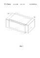
- FIG. 1 illustrates the representation of a 3-D image as displayed on a monitor in accordance with the present invention
- FIG. 2 illustrates a method for projecting a three-dimensional stereoscopic image on a monitor in accordance with the present invention
- FIG. 3 illustrates representations of specific images as implemented by the method of FIG. 2.
- FIG. 4 illustrates another set of images corresponding to the method steps of FIG. 2 .
- left and right eye images are blended in order to generate a 3-D stereoscopic image on a computer monitor.
- a mask or a stencil is used to specify which portions of a left eye image, and a right eye image are actually implemented on a data screen.
- mutually exclusive left and right eye stenciling techniques it is possible for images whether solid or linear, to be displayed in 3-D using a standard refresh rate.
- FIG. 1 illustrates a stereoscopic image, as viewed on a monitor that includes a simultaneously generated left eye image 102 and a right eye image 101 .
- the left eye image and the right eye image will be generated using different complementary colors. Generally, blue and red are used for respective individual images.
- By controlling the depth of color of these images it is possible to provide varying shades of a color.
- each eye When viewed through eye-glasses having a left and right eye lenses of complementary colors, each eye will be able to view its associated complementary color image from the screen. Thereby, the lens having the same complementary color as shape 101 will only be able to see shape 101 , and the shape 102 would not be visible to that eye. Likewise, the lens having the same color as shape 102 would only be able to perceive the shape 102 .
- FIG. 2 illustrates a method for providing the 3-D images of FIG. 1 onto a computer monitor.
- the method of FIG. 2 can be better understood with reference to the images of FIG. 3, which correspond to the specific steps of FIG. 2 .
- a left eye image of a shape (not shown) is created using one of two complementary primary colors.
- Shape 310 corresponds to providing this left eye image.
- the primary color of the left eye will generally be either blue or red.
- a right eye image is generated from a complementary primary color not used in step 201 . This image corresponds to the shape 320 of FIG. 3 .
- a first stencil is applied to the left eye image.
- the purpose of the stencil is to assure that each image is transmitted with an appropriate amount of data onto the monitor to allow for the image to be seen.
- Stencil 311 of FIG. 3 illustrates one such stencil.
- the stencil 311 has an alternating checkerboard pattern, whereby every other pixel in a horizontal or vertical orientation is active.
- An active space on the stencil 311 corresponds to a pixel location, which will allow one or more pixels to be transmitted.
- the stencil 311 as illustrated in FIG. 3 will transmit pixels through the clear locations, and would absorb pixel information in the shaded areas.
- a second stencil is used in order to generate a stenciled right eye image.
- stencil 321 illustrates a second such stencil. Note that a similar checkerboard pattern as that of stencil 311 is used. However, the stencil 321 has active locations mutually exclusive of those in stencil 311 . In other words, locations that are active in stencil 311 are inactive, or shaded, in stencil 321 . In other embodiments, it will be possible to use other stencil patterns. In addition, it would be possible to have some stencil locations overlapping. In other words, the active and inactive areas need not be completely mutually exclusive between the first and the second stencils.
- a stencil having greater overlapping than approximately 20% may reduce video quality to the extent that the overlapping will be visible to the user and thereby not practical.
- the stenciled left eye image and the stenciled right eye image are merged into a single image.
- This merged image represents a frame of data corresponding to the image of FIG. 1 .
- the image of FIG. 1, and the image created by combining the stenciled left and right eye images 312 and 322 of FIG. 3 is that the merged image of stenciled images 312 and 322 will look perforated because the stencils 311 and 321 will remove a portion of each image.
- the image when viewed with appropriate 3-D lenses, the image will look as a solid image because the image viewed by the user will have the left and right eye stenciled images coincident with one another, thereby filling the voids that occur.
- FIG. 4 corresponds to the illustrations of FIG. 3 .
- the image 410 has been shifted from image 420 by one feature size of the stencil 411 .
- a feature size of stencil 411 is the width of one of the checker board squares which mask the image.
- stencil 411 is equivalent to stencil 421 shifted by one feature size.
- the stenciled left eye image 412 and the stenciled right eye image 422 are identical images, except for the offset.
- stenciled images 413 and 423 are identical to one another.
- the result of having identical left and right-eyed images is that a flicker of the viewed stereoscopic image can occur.
- One way of resolving this situation is to base the feature size of the stencil on the image. By choosing the feature size to be different from the amount that the image is to be shifted will avoid the flicker problem.
- the feature size can also be based on a pixel size, with the smallest feature size being one pixel.
- the specific method put forth herein can be executed upon a computer system having a data processor.
- the data processor would generally execute instruction capable of implementing the images, and the stenciling of the images discussed herein.
- the data processor may include a processing module and memory.
- the processing module may be a single processing device or a plurality of processing devices.
- Such a processing device may be a microprocessor, microcontroller, digital signal processor, microcomputer, portion of the central processing unit, state machine, logic circuitry, and/or any device that manipulates signals (e.g., analog or digital) based on operational instructions.
- the memory may be a single memory device or a plurality of memory devices.
- Such a memory device may be a read-only memory, random access memory, floppy disk memory, magnetic tape memory, erasable memory, portion of system memory, and/or any device that stores operational instructions in a digital format. Note that when the processing module implements one or more of its functions via a state machine or logic circuitry, the memory storing the corresponding operational instructions is embedded within the circuitry comprising the state machine and/or logic circuitry.
- each of the left and right eye images can be generated by dedicated hardware, or specialized software instructions.
- the left and right eye images can then be combined also using specialized hardware or software in order to produce a frame capable of being rendered on a video monitor.
- the present invention discloses a method of implementing a stereoscopic 3-D image on a conventional video monitor without the need for expensive techniques or lenses.
- One of ordinary skill in the art will readily recognize that multiple variations of the present invention could be incorporated without departing from the scope of the present invention.
- various stencil patterns could be used in order to meet specific objectives of applications, and varying primary colors other than red and blue could be used.
Abstract
Description
Claims (25)
Priority Applications (1)
| Application Number | Priority Date | Filing Date | Title |
|---|---|---|---|
| US09/295,949 US6552697B1 (en) | 1999-04-21 | 1999-04-21 | Method and apparatus for generating stereoscopic three-dimensional images |
Applications Claiming Priority (1)
| Application Number | Priority Date | Filing Date | Title |
|---|---|---|---|
| US09/295,949 US6552697B1 (en) | 1999-04-21 | 1999-04-21 | Method and apparatus for generating stereoscopic three-dimensional images |
Publications (1)
| Publication Number | Publication Date |
|---|---|
| US6552697B1 true US6552697B1 (en) | 2003-04-22 |
Family
ID=23139920
Family Applications (1)
| Application Number | Title | Priority Date | Filing Date |
|---|---|---|---|
| US09/295,949 Expired - Lifetime US6552697B1 (en) | 1999-04-21 | 1999-04-21 | Method and apparatus for generating stereoscopic three-dimensional images |
Country Status (1)
| Country | Link |
|---|---|
| US (1) | US6552697B1 (en) |
Cited By (4)
| Publication number | Priority date | Publication date | Assignee | Title |
|---|---|---|---|---|
| US20050162440A1 (en) * | 2004-01-28 | 2005-07-28 | Siemens Aktiengesellschaft | Device for generating a view of a three-dimensional object |
| US20080246694A1 (en) * | 2007-04-06 | 2008-10-09 | Ronald Fischer | Personal theater display |
| US20110242282A1 (en) * | 2010-04-05 | 2011-10-06 | Sony Corporation | Signal processing device, signal processing method, display device, and program product |
| US20130083164A1 (en) * | 2011-10-03 | 2013-04-04 | EchoStar Technologies, Inc. | Active 3d to passive 3d conversion |
Citations (10)
| Publication number | Priority date | Publication date | Assignee | Title |
|---|---|---|---|---|
| US4286286A (en) * | 1979-05-02 | 1981-08-25 | Honeywell Inc. | Photo controlled stereoscopic television system |
| US4424529A (en) * | 1977-11-23 | 1984-01-03 | Roese John A | Remotely triggered portable stereoscopic viewer system |
| US4562463A (en) * | 1981-05-15 | 1985-12-31 | Stereographics Corp. | Stereoscopic television system with field storage for sequential display of right and left images |
| US4647965A (en) * | 1983-11-02 | 1987-03-03 | Imsand Donald J | Picture processing system for three dimensional movies and video systems |
| US5883739A (en) * | 1993-10-04 | 1999-03-16 | Honda Giken Kogyo Kabushiki Kaisha | Information display device for vehicle |
| US5905499A (en) * | 1995-07-05 | 1999-05-18 | Fakespace, Inc. | Method and system for high performance computer-generated virtual environments |
| US5917940A (en) * | 1996-01-23 | 1999-06-29 | Nec Corporation | Three dimensional reference image segmenting method and device and object discrimination system |
| US5933127A (en) * | 1996-12-06 | 1999-08-03 | The Rowland Institute For Science | Electronic stereoscopic display |
| US6005607A (en) * | 1995-06-29 | 1999-12-21 | Matsushita Electric Industrial Co., Ltd. | Stereoscopic computer graphics image generating apparatus and stereoscopic TV apparatus |
| US6195205B1 (en) * | 1991-12-18 | 2001-02-27 | Reveo, Inc. | Multi-mode stereoscopic imaging system |
-
1999
- 1999-04-21 US US09/295,949 patent/US6552697B1/en not_active Expired - Lifetime
Patent Citations (10)
| Publication number | Priority date | Publication date | Assignee | Title |
|---|---|---|---|---|
| US4424529A (en) * | 1977-11-23 | 1984-01-03 | Roese John A | Remotely triggered portable stereoscopic viewer system |
| US4286286A (en) * | 1979-05-02 | 1981-08-25 | Honeywell Inc. | Photo controlled stereoscopic television system |
| US4562463A (en) * | 1981-05-15 | 1985-12-31 | Stereographics Corp. | Stereoscopic television system with field storage for sequential display of right and left images |
| US4647965A (en) * | 1983-11-02 | 1987-03-03 | Imsand Donald J | Picture processing system for three dimensional movies and video systems |
| US6195205B1 (en) * | 1991-12-18 | 2001-02-27 | Reveo, Inc. | Multi-mode stereoscopic imaging system |
| US5883739A (en) * | 1993-10-04 | 1999-03-16 | Honda Giken Kogyo Kabushiki Kaisha | Information display device for vehicle |
| US6005607A (en) * | 1995-06-29 | 1999-12-21 | Matsushita Electric Industrial Co., Ltd. | Stereoscopic computer graphics image generating apparatus and stereoscopic TV apparatus |
| US5905499A (en) * | 1995-07-05 | 1999-05-18 | Fakespace, Inc. | Method and system for high performance computer-generated virtual environments |
| US5917940A (en) * | 1996-01-23 | 1999-06-29 | Nec Corporation | Three dimensional reference image segmenting method and device and object discrimination system |
| US5933127A (en) * | 1996-12-06 | 1999-08-03 | The Rowland Institute For Science | Electronic stereoscopic display |
Cited By (8)
| Publication number | Priority date | Publication date | Assignee | Title |
|---|---|---|---|---|
| US20050162440A1 (en) * | 2004-01-28 | 2005-07-28 | Siemens Aktiengesellschaft | Device for generating a view of a three-dimensional object |
| DE102004004296A1 (en) * | 2004-01-28 | 2005-08-25 | Siemens Ag | Device for generating a view with a spatial impression of a spatial object |
| US7820954B2 (en) | 2004-01-28 | 2010-10-26 | Siemens Aktiengesellschaft | Device for generating a view of a three-dimensional object |
| US20080246694A1 (en) * | 2007-04-06 | 2008-10-09 | Ronald Fischer | Personal theater display |
| US7898504B2 (en) * | 2007-04-06 | 2011-03-01 | Sony Corporation | Personal theater display |
| US20110242282A1 (en) * | 2010-04-05 | 2011-10-06 | Sony Corporation | Signal processing device, signal processing method, display device, and program product |
| US20130083164A1 (en) * | 2011-10-03 | 2013-04-04 | EchoStar Technologies, Inc. | Active 3d to passive 3d conversion |
| US9883172B2 (en) * | 2011-10-03 | 2018-01-30 | Echostar Technologies L.L.C. | Active 3D to passive 3D conversion |
Similar Documents
| Publication | Publication Date | Title |
|---|---|---|
| US6532008B1 (en) | Method and apparatus for eliminating steroscopic cross images | |
| RU2201609C2 (en) | Process of data display for users located together but intended for individual persons | |
| US8400492B2 (en) | Projection of stereoscopic images using linearly polarized light | |
| JP3978515B2 (en) | 3D image display method and apparatus | |
| RU2313191C2 (en) | Method and system for generation of a stereo image | |
| CN104539935B (en) | The adjusting method and adjusting means of brightness of image, display device | |
| US20080144967A1 (en) | Confidential Viewing System Utilizing Spatial Multiplexing | |
| US8817043B2 (en) | System and method for selective viewing of a hidden presentation within a displayed presentation | |
| CN202168171U (en) | Three-dimensional image display system | |
| GB2351866A (en) | Stereoscopic display | |
| JP2010507332A (en) | Dual ZScreen (R) projection | |
| JPH0949986A (en) | Spatial optical modulator and directional display | |
| CN102651819B (en) | Peep-proof method and 3D (three-dimensional) display device | |
| Dodgson et al. | A time‐sequential multi‐projector autostereoscopic display | |
| KR20100022653A (en) | 3-dimensional display | |
| JP2007537463A (en) | Display system that keeps images secret by spatial multiplexing | |
| US6552697B1 (en) | Method and apparatus for generating stereoscopic three-dimensional images | |
| RU2326507C1 (en) | Stereo image generation system | |
| US20070242090A1 (en) | Apparatus and method for setup frame sequencing in color sequential display systems | |
| US5691843A (en) | Enhanced depth perception in a two-dimensional image | |
| US20070024642A1 (en) | Multi-plane display for displaying overlapping images | |
| JP2001508617A (en) | Method and apparatus for creating stereoscopic images | |
| US20220020132A1 (en) | Device and method for enhancing images | |
| CN111866479B (en) | Liquid crystal polarization invisible word-drawing DLP projector system and video data processing method | |
| RU51241U1 (en) | STEREO IMAGE FORMATION SYSTEM |
Legal Events
| Date | Code | Title | Description |
|---|---|---|---|
| AS | Assignment |
Owner name: ATI INTERNATIONAL, SRL, BARBADOS Free format text: ASSIGNMENT OF ASSIGNORS INTEREST;ASSIGNOR:OLUTA, LAWRENCE J.M.;REEL/FRAME:009905/0986 Effective date: 19990420 |
|
| STCF | Information on status: patent grant |
Free format text: PATENTED CASE |
|
| FPAY | Fee payment |
Year of fee payment: 4 |
|
| AS | Assignment |
Owner name: ATI TECHNOLOGIES ULC, CANADA Free format text: ASSIGNMENT OF ASSIGNORS INTEREST;ASSIGNOR:ATI INTERNATIONAL SRL;REEL/FRAME:023574/0593 Effective date: 20091118 Owner name: ATI TECHNOLOGIES ULC,CANADA Free format text: ASSIGNMENT OF ASSIGNORS INTEREST;ASSIGNOR:ATI INTERNATIONAL SRL;REEL/FRAME:023574/0593 Effective date: 20091118 |
|
| FPAY | Fee payment |
Year of fee payment: 8 |
|
| FPAY | Fee payment |
Year of fee payment: 12 |