US6554545B1 - Framework and method of forming a support structure with interlocking of adjacent compartments - Google Patents
Framework and method of forming a support structure with interlocking of adjacent compartments Download PDFInfo
- Publication number
- US6554545B1 US6554545B1 US09/701,665 US70166500A US6554545B1 US 6554545 B1 US6554545 B1 US 6554545B1 US 70166500 A US70166500 A US 70166500A US 6554545 B1 US6554545 B1 US 6554545B1
- Authority
- US
- United States
- Prior art keywords
- compartments
- framework
- compartment
- adjacent
- support structure
- Prior art date
- Legal status (The legal status is an assumption and is not a legal conclusion. Google has not performed a legal analysis and makes no representation as to the accuracy of the status listed.)
- Expired - Fee Related
Links
Images


Classifications
-
- E—FIXED CONSTRUCTIONS
- E02—HYDRAULIC ENGINEERING; FOUNDATIONS; SOIL SHIFTING
- E02D—FOUNDATIONS; EXCAVATIONS; EMBANKMENTS; UNDERGROUND OR UNDERWATER STRUCTURES
- E02D17/00—Excavations; Bordering of excavations; Making embankments
- E02D17/20—Securing of slopes or inclines
-
- E—FIXED CONSTRUCTIONS
- E01—CONSTRUCTION OF ROADS, RAILWAYS, OR BRIDGES
- E01C—CONSTRUCTION OF, OR SURFACES FOR, ROADS, SPORTS GROUNDS, OR THE LIKE; MACHINES OR AUXILIARY TOOLS FOR CONSTRUCTION OR REPAIR
- E01C11/00—Details of pavings
- E01C11/16—Reinforcements
- E01C11/18—Reinforcements for cement concrete pavings
- E01C11/185—Reinforcements for cement concrete pavings the reinforcements extending up to the surface, e.g. anti-slip gratings
-
- E—FIXED CONSTRUCTIONS
- E01—CONSTRUCTION OF ROADS, RAILWAYS, OR BRIDGES
- E01C—CONSTRUCTION OF, OR SURFACES FOR, ROADS, SPORTS GROUNDS, OR THE LIKE; MACHINES OR AUXILIARY TOOLS FOR CONSTRUCTION OR REPAIR
- E01C3/00—Foundations for pavings
- E01C3/006—Foundations for pavings made of prefabricated single units
-
- E—FIXED CONSTRUCTIONS
- E02—HYDRAULIC ENGINEERING; FOUNDATIONS; SOIL SHIFTING
- E02D—FOUNDATIONS; EXCAVATIONS; EMBANKMENTS; UNDERGROUND OR UNDERWATER STRUCTURES
- E02D17/00—Excavations; Bordering of excavations; Making embankments
- E02D17/20—Securing of slopes or inclines
- E02D17/202—Securing of slopes or inclines with flexible securing means
-
- Y—GENERAL TAGGING OF NEW TECHNOLOGICAL DEVELOPMENTS; GENERAL TAGGING OF CROSS-SECTIONAL TECHNOLOGIES SPANNING OVER SEVERAL SECTIONS OF THE IPC; TECHNICAL SUBJECTS COVERED BY FORMER USPC CROSS-REFERENCE ART COLLECTIONS [XRACs] AND DIGESTS
- Y10—TECHNICAL SUBJECTS COVERED BY FORMER USPC
- Y10T—TECHNICAL SUBJECTS COVERED BY FORMER US CLASSIFICATION
- Y10T428/00—Stock material or miscellaneous articles
- Y10T428/24—Structurally defined web or sheet [e.g., overall dimension, etc.]
- Y10T428/24149—Honeycomb-like
- Y10T428/24157—Filled honeycomb cells [e.g., solid substance in cavities, etc.]
-
- Y—GENERAL TAGGING OF NEW TECHNOLOGICAL DEVELOPMENTS; GENERAL TAGGING OF CROSS-SECTIONAL TECHNOLOGIES SPANNING OVER SEVERAL SECTIONS OF THE IPC; TECHNICAL SUBJECTS COVERED BY FORMER USPC CROSS-REFERENCE ART COLLECTIONS [XRACs] AND DIGESTS
- Y10—TECHNICAL SUBJECTS COVERED BY FORMER USPC
- Y10T—TECHNICAL SUBJECTS COVERED BY FORMER US CLASSIFICATION
- Y10T428/00—Stock material or miscellaneous articles
- Y10T428/24—Structurally defined web or sheet [e.g., overall dimension, etc.]
- Y10T428/24273—Structurally defined web or sheet [e.g., overall dimension, etc.] including aperture
- Y10T428/24322—Composite web or sheet
-
- Y—GENERAL TAGGING OF NEW TECHNOLOGICAL DEVELOPMENTS; GENERAL TAGGING OF CROSS-SECTIONAL TECHNOLOGIES SPANNING OVER SEVERAL SECTIONS OF THE IPC; TECHNICAL SUBJECTS COVERED BY FORMER USPC CROSS-REFERENCE ART COLLECTIONS [XRACs] AND DIGESTS
- Y10—TECHNICAL SUBJECTS COVERED BY FORMER USPC
- Y10T—TECHNICAL SUBJECTS COVERED BY FORMER US CLASSIFICATION
- Y10T428/00—Stock material or miscellaneous articles
- Y10T428/24—Structurally defined web or sheet [e.g., overall dimension, etc.]
- Y10T428/24628—Nonplanar uniform thickness material
- Y10T428/24669—Aligned or parallel nonplanarities
- Y10T428/24694—Parallel corrugations
- Y10T428/24711—Plural corrugated components
Definitions
- This invention relates to a method of forming a support structure on a base, and to a framework for use in forming such a support structure.
- support structures such as roadways, canal or river or bank linings, mine packs, sea walls or the like from a material having a honeycomb structure, i.e. having a plurality of compartments or cells divided by dividing walls, each compartment or cell being filled with a suitable filler material.
- honeycomb structure i.e. having a plurality of compartments or cells divided by dividing walls, each compartment or cell being filled with a suitable filler material.
- suitable filler material HYSON-CELLS from M&S Technical Consultants & Services (Pty) Limited
- GEOWEB from Presto Products Co.
- Tenweb Tenax Corp
- ARMATER from Crow Company
- TERRACELL FROM Webtec Inc. ENVIROGRID from Akzo Nobel Geosynthetics Co.
- GEOCELLS from Kaytech.
- the walls of the compartments In making a support structure using these materials, it has generally been the practice for the walls of the compartments to be substantially planar, i.e flat, in use. This has lead to the result that the filler material, particularly when it is cement based, in certain circumstances shrinks away from the walls of the compartments during use of the support structure, thus creating gaps in the support structure and reducing any support of one compartment by adjacent compartments. This in turn results in the support structure not being able to take as great a load as may be desired.
- a method of forming a support structure on a base from a framework comprising a tube of a flexible material divided by dividing walls of a flexible material into an array of compartments or cells running the length of the tube, the compartments being arranged in rows and columns so that the tube divided by dividing walls has a honeycomb structure, a wall or walls of each compartment including one or more hollow protrusions or one or more hollow recesses, or both, which method comprises the steps of:
- each compartment is adjacent to one or more other compartments filled with the filler material to support and be supported by the adjacent compartments, and so that each hollow protrusion in a compartment wall fills with the filler material so that each compartment protrudes into or is protruded into by at least one adjacent compartment so as to interlock adjacent compartments.
- the protrusions or recesses must be of a size and shape to achieve interlocking of the filler material in one compartment with the filler material in an adjacent compartment, with the common wall between the compartment still separating the filler materials in the two compartments and thus acting as an expansion joint. In this way the overall strength of the support structure formed is increased, and there is also increased resistance against the filler material in one compartment being pushed or pulled out of that compartment.
- the protrusion of one compartment into another adjacent compartment allows any load applied to the support structure to be transferred across the support structure, and thus assists in preventing fracture or disintegration of the support structure, which in turn allows the support structure to accept greater loads.
- a wall of a first compartment adjacent to a second compartment is also a wall of that second compartment, and thus that a protrusion in this wall of the first compartment equates to a recess in this wall of the second compartment.
- the protrusions or recesses may have any suitable shape, such as for example curved or rounded shapes, a dovetail shape, a T-shape, a block shape, or a pyramidal shape or the like.
- the protrusions and recesses are curved or rounded so as to allow for a degree of rotation between adjacent compartments during filling and setting of the filler material, and to prevent any shearing of the protrusions from the remainder of the filler material in the relevant compartment on application of a load to the support structure.
- each protrusion may be shaped substantially as a hemisphere or as a section of a sphere less than a hemisphere. In other words the protrusion may be approximately dome shaped. Alternatively, each protrusion may be shaped substantially as a semi cylinder or as a section of a cylinder less than a semi cylinder. Clearly, the recesses will have the complimentary shape.
- a wall of a compartment may include one protrusion or recess, or may include two or more protrusions or two or more recesses, or a combination of protrusions and recesses.
- Each compartment may have a single wall including a protrusion or a recess, or two or more or all of the walls including a protrusion or a recess.
- each wall of each compartment includes at least one protrusion or at least one recess.
- the framework i.e the tube and the dividing walls, may be made from any suitable flexible material. Although the material must possess some degree of flexibility, the degree of flexibility may range from very flexible up to semi rigid.
- the flexible material may be for example a plastics material such as for example a co-extruded or a biaxially extruded plastics material; a plastics laminate material such as for example a laminate of a plastics material and a metallic material or a textile material; a metallic material; a woven or non-woven textile material; a paper or cardboard material; and the like.
- the flexible material is preferably a suitable plastics material.
- the filler material may be any suitable filler material such as for example an inert filler material. e.g sand or gravel or the like, or a composition comprising a filler material and a settable binder therefor.
- suitable filler material such as for example an inert filler material. e.g sand or gravel or the like, or a composition comprising a filler material and a settable binder therefor. Examples of such compositions include:
- an inert filler material such as sand or gravel or the like, and a cementitious binder, for example ordinary Portland Cement;
- a filler material such as soil treated with a suitable chemical composition such as calcium chloride, a lignin sulphonate or an ionic liquid to cause the soil to bind or set;
- a filler material such as sand or gravel or the like and a resin binder
- a resin binder for example (a) a thermosetting resin such as polyurethanes and polyesters, (b) a thermoplastic resin such as polyethylene, EVA, or PVC, and (c) a suitable wax.
- the settable composition may include a conventional foam or foaming agent so that the final set composition is a foamed composition, to reduce the weight thereof.
- the filler material is preferably a fluid or paste which sets into a strong, rigid solid conforming to the geometry of the confining compartment walls.
- the filler material preferably includes a binder such as a cementitious material, e.g the filler material may be a concrete material having a high slump value, in particular greater than 150, to which chemical additives have been added to aid setting.
- a binder such as a cementitious material
- the filler material may be a concrete material having a high slump value, in particular greater than 150, to which chemical additives have been added to aid setting.
- the framework may have any suitable height and any suitable compartment size.
- the height of the framework may range from 2 mm to 10 m inclusive, and each compartment may have a wall length of from 5 mm up to 2 m.
- compartments in the framework may have any suitable cross-section, such as square, hexagonal or octagonal, but preferably have a square cross-section. i.e each compartment is defined by four walls of substantially equal length.
- the support structure may be made from a single framework as described above, or the support structure may be made from a plurality of frameworks laid side-by-side on the base, each framework being as described above and being filled with the filler material as described above.
- the compartments along an edge of a first framework will protrude into or be protruded into by the compartments along an adjacent edge of an adjacent framework, to interlock the frameworks one to another to form the support structure.
- a framework in use in forming a support structure on a base comprising a tube of a flexible material divided by dividing walls of a flexible material into an array of compartments or cells running the length of the tube, the compartments being arranged in rows and columns so that the tube divided by dividing walls has a honeycomb structure, a wall or walls of each compartment including one or more hollow protrusions or one or more hollow recesses or both, so that, in use, when the compartments are filled with a filler material, each hollow protrusion in a compartment wall fills with the filler material so that each compartment protrudes into or is protruded into by at least one adjacent compartment to interlock adjacent compartments.
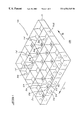
- FIG. 1 is a schematic perspective view of a framework of the invention
- FIG. 2 is a partial perspective view of a section of a further framework according to the invention.
- FIGS. 3A and 3B to 11 A and 11 B are cross sectional views of various compartment walls through the centre of the protrusions therein and side views of the same compartment walls, respectively.
- the first aspect of the invention is a method of forming a support structure on a base and this method will be described in more detail with reference to FIG. 1 .
- a framework 10 comprising a tube 12 of a flexible material divided by dividing walls 14 of a flexible material into an array of compartments 16 running the length of the tube 12 .
- the compartments 16 are arranged in rows running in the direction of the arrow B and columns running in the direction of the arrow C, so that the tube 12 divided by dividing walls 14 has a honeycomb structure as shown.
- each compartment 16 is defined by four walls.
- the compartment 16 A which is defined by walls 20 , 22 , 24 and 26 .
- the wall 20 of compartment 16 A also forms a wall of the adjacent cell 16 B
- the wall 22 of compartment 16 A also forms a wall of the compartment 16 C
- the wall 24 of compartment 16 A also forms a wall of the compartment 16 D.
- the wall 26 of compartment 16 A is an outside wall which may either be the outside wall of the support structure in use, or may abut an outside wall of an adjacent framework 10 .
- the wall 20 includes a protrusion 28 (which in turn is a recess in the compartment 16 B), the wall 22 includes a protrusion 30 (which in turn is a recess in the compartment 16 C), the wall 24 includes a recess 32 (which in turn is a protrusion in the compartment 16 D) and the wall 26 includes a recess 34 .
- the compartment 16 A When the compartment 16 A is filled with the filler material, the compartment 16 A will protrude into the compartments 16 B and 16 C and will be protruded into by compartment 16 D and any adjacent compartment of an adjacent framework 10 abutting the wall 26 .
- each compartment 16 is again defined by four walls, but only two of the four walls include protrusions or recesses 36 .
- the compartment 16 E it protrudes into the adjacent compartment 16 F and is protruded into by the adjacent compartment 16 G, but does not protrude into or is not protruded into by the adjacent compartments 16 H and 16 I. Nevertheless, the compartment 16 E is sufficiently interlocked with its neighbours to achieve the desired result, viz. an increase in the strength of the support structure of which the framework 10 forms a part.
- protrusions 28 , 30 32 , 34 36 are rounded, they allow any load applied to the support structure of which the framework 10 forms a part, to be transferred across the support structure, and thus assist in preventing fracture or disintegration of the support structure, which in turn allows the support structure to accept greater loads.
- the framework 10 is used to form a support structure on the base 18 as follows. Firstly, the framework 10 may be supported in position on the base in any suitable manner, for example by the use of flexible strings or rigid stays as is disclosed in our co-pending patent application.
- each protrusion 28 , 30 , 32 , 34 , 36 also fills with the filler material so that each compartment 16 protrudes into or is protruded into by at least one adjacent compartment 16 to interlock adjacent compartment 16 .
- each protrusion or recess is curved or rounded and each transition between the plane of the wall and the protrusion or recess is curved or rounded, this allows a degree of rotation between the blocks of filler material in adjacent compartments 16 during filling and setting of the filler material. This rotation allows the blocks of filler material in the adjacent compartment 16 to align so that the support structure so formed can receive a load which is then transferred across the support structure.
- the curved or rounded shape of each protrusion or recess and transition areas also prevents any shearing of the filler material in each protrusion or recess from the remainder of the filler material in a compartment 16 on application of a load.
- the protrusions or recesses formed in the walls of the compartment 16 may take various shapes, some of which are illustrated in FIGS. 2 to 11 .
- FIG. 2 there is illustrated two compartments 40 of a framework, wherein the walls of the compartments 40 include a plurality of hollow pockets or bubbles 42 .
- the filler material When a filler material is placed into the compartments 40 , the filler material fills the pockets 42 which then press into the adjacent compartments 40 to cause the protrusion of one compartment 40 into an adjacent compartment 40 to cause, eventually interlocking of the compartments 40 in the final support structure.
- FIGS. 3A and 3B Various other protrusion shapes are illustrated in FIGS. 3A and 3B to 7 A and 7 B.
- a wall 50 of a compartment includes a protrusion 52 which is hemispherical in shape. From FIGS. 3A and 3B, it can clearly be seen that a protrusion 52 in a wall 50 of a first compartment also constitutes a recess in a wall 50 of a second adjacent compartment. It can also be seen that the transition from the plane of the wall 50 to the protrusion 52 , illustrated at 53 , is also curved, for the reasons stated above.
- a wall 54 of a compartment includes two protrusions 56 . Again each protrusion 56 is hemispherical in shape.
- a wall 58 includes a recess 60 and a protrusion 62 . Again the protrusion 60 and the recess 62 are hemispherical in shape.
- a wall 64 includes a protrusion 66 which is shaped as a semi-cylinder which runs the width of the wall 64 .
- a wall 68 includes a protrusion 70 which is again is shaped as a semi-cylinder but which runs the height of the wall 68 .
- a wall 72 includes a protrusion 74 which is pyramidal in shape.
- a wall 76 includes a protrusion 78 which is T-shaped in cross-section.
- a wall 80 includes a protrusion 82 which is block shaped.
- a wall 84 includes a protrusion 86 which is dovetail shape.
- protrusions and recesses may be designed, provided that the protrusions and recesses are of a sufficient size to ensure protrusion of one compartment into an adjacent compartment to provide interlocking.
- the filler material in the compartment must interlock with the filler material in the adjacent compartment to increase the strength of the support structure and to provide resistance against the filler material in one compartment from being pushed or pulled out of the compartment.
- the wall between two adjacent compartments acts as an expansion joint.
- the protrusions or recesses in the walls of the compartments may be made in any suitable manner.
- the necessary protrusions or recesses may be formed by heating a suitably shaped tool and then pressing the heated tool into the plastics material, or by vacuum moulding, or by pressing.
- the flexible material of the framework is a woven or non-woven textile material
- the necessary protrusions and recesses may be formed during manufacture of the textile material.
- a support structure made using a framework of the invention i.e one including plurality of protrusions and recesses, can support a load which is up to 80% greater than an equivalent support structure made with a framework which does not include such protrusions or recesses.
- a number of frameworks will be placed side-by-side on the base, and then each framework will be filled with a filler material as described.
- adjacent compartments of one framework may interlock with adjacent edge compartments of an adjacent framework, thus providing a support structure which posseses the desired features of the invention, viz. protrusion of adjacent compartments into one another to provide for interlocking and transfer of load.
- the support structure formed according to the method of the invention may be for example a roadway or a paved area; a lining for a canal, river, drain or spillway or the like; a support for an embankment; a dam or harbour wall; or any other suitable support structure.
Abstract
A method of forming a support structure on a base from a framework uses a tube of a flexible material divided by dividing walls of flexible material into an array of compartments. Each compartment includes at least one wall including a hollow protrusion or recess. In use the framework is located on the base and the compartments are filled with the filler material so that each compartment is adjacent to one or more other compartments filled with the filler material and so that each hollow protrusion fills with the filler material so that each compartment protrudes into or is protruded into by at least one adjacent compartment so as to interlock adjacent compartment. This increases the overall strength of the support structure.
Description
This invention relates to a method of forming a support structure on a base, and to a framework for use in forming such a support structure.
It is well known to form support structures such as roadways, canal or river or bank linings, mine packs, sea walls or the like from a material having a honeycomb structure, i.e. having a plurality of compartments or cells divided by dividing walls, each compartment or cell being filled with a suitable filler material. Examples of such materials for use in these support structures are HYSON-CELLS from M&S Technical Consultants & Services (Pty) Limited, GEOWEB from Presto Products Co., Tenweb from Tenax Corp, ARMATER from Crow Company, TERRACELL FROM Webtec Inc., ENVIROGRID from Akzo Nobel Geosynthetics Co. and GEOCELLS from Kaytech.
In making a support structure using these materials, it has generally been the practice for the walls of the compartments to be substantially planar, i.e flat, in use. This has lead to the result that the filler material, particularly when it is cement based, in certain circumstances shrinks away from the walls of the compartments during use of the support structure, thus creating gaps in the support structure and reducing any support of one compartment by adjacent compartments. This in turn results in the support structure not being able to take as great a load as may be desired.
There is thus need for a method of overcoming this problem.
According to a first aspect of the invention there is provided a method of forming a support structure on a base from a framework comprising a tube of a flexible material divided by dividing walls of a flexible material into an array of compartments or cells running the length of the tube, the compartments being arranged in rows and columns so that the tube divided by dividing walls has a honeycomb structure, a wall or walls of each compartment including one or more hollow protrusions or one or more hollow recesses, or both, which method comprises the steps of:
(1) locating the framework on the base;
(2) filling the compartments with a filler material so that each compartment is adjacent to one or more other compartments filled with the filler material to support and be supported by the adjacent compartments, and so that each hollow protrusion in a compartment wall fills with the filler material so that each compartment protrudes into or is protruded into by at least one adjacent compartment so as to interlock adjacent compartments.
The protrusions or recesses must be of a size and shape to achieve interlocking of the filler material in one compartment with the filler material in an adjacent compartment, with the common wall between the compartment still separating the filler materials in the two compartments and thus acting as an expansion joint. In this way the overall strength of the support structure formed is increased, and there is also increased resistance against the filler material in one compartment being pushed or pulled out of that compartment.
The protrusion of one compartment into another adjacent compartment allows any load applied to the support structure to be transferred across the support structure, and thus assists in preventing fracture or disintegration of the support structure, which in turn allows the support structure to accept greater loads.
It is to be noted that a wall of a first compartment adjacent to a second compartment is also a wall of that second compartment, and thus that a protrusion in this wall of the first compartment equates to a recess in this wall of the second compartment.
As indicated above the protrusions or recesses may have any suitable shape, such as for example curved or rounded shapes, a dovetail shape, a T-shape, a block shape, or a pyramidal shape or the like.
For certain applications, where the support structure is intended to receive a load, the protrusions and recesses are curved or rounded so as to allow for a degree of rotation between adjacent compartments during filling and setting of the filler material, and to prevent any shearing of the protrusions from the remainder of the filler material in the relevant compartment on application of a load to the support structure.
When the protrusions and recesses are curved or rounded, each protrusion may be shaped substantially as a hemisphere or as a section of a sphere less than a hemisphere. In other words the protrusion may be approximately dome shaped. Alternatively, each protrusion may be shaped substantially as a semi cylinder or as a section of a cylinder less than a semi cylinder. Clearly, the recesses will have the complimentary shape.
In this case it is also important that the transition from the plane of the wall to the protrusion or recess be curved, again to prevent the shearing of the protrusion from the remainder of the filler material in the relevant compartment on application of a load.
A wall of a compartment may include one protrusion or recess, or may include two or more protrusions or two or more recesses, or a combination of protrusions and recesses.
Each compartment may have a single wall including a protrusion or a recess, or two or more or all of the walls including a protrusion or a recess.
Preferably, each wall of each compartment includes at least one protrusion or at least one recess.
The framework, i.e the tube and the dividing walls, may be made from any suitable flexible material. Although the material must possess some degree of flexibility, the degree of flexibility may range from very flexible up to semi rigid. The flexible material may be for example a plastics material such as for example a co-extruded or a biaxially extruded plastics material; a plastics laminate material such as for example a laminate of a plastics material and a metallic material or a textile material; a metallic material; a woven or non-woven textile material; a paper or cardboard material; and the like.
The flexible material is preferably a suitable plastics material.
The filler material may be any suitable filler material such as for example an inert filler material. e.g sand or gravel or the like, or a composition comprising a filler material and a settable binder therefor. Examples of such compositions include:
(i) an inert filler material such as sand or gravel or the like, and a cementitious binder, for example ordinary Portland Cement;
(ii) an inert filler material such as sand or gravel or the like and a bituminous binder;
(iii) a filler material such as soil treated with a suitable chemical composition such as calcium chloride, a lignin sulphonate or an ionic liquid to cause the soil to bind or set;
(iv) a filler material such as sand or gravel or the like and a resin binder, for example (a) a thermosetting resin such as polyurethanes and polyesters, (b) a thermoplastic resin such as polyethylene, EVA, or PVC, and (c) a suitable wax.
The settable composition may include a conventional foam or foaming agent so that the final set composition is a foamed composition, to reduce the weight thereof.
The filler material is preferably a fluid or paste which sets into a strong, rigid solid conforming to the geometry of the confining compartment walls.
The filler material preferably includes a binder such as a cementitious material, e.g the filler material may be a concrete material having a high slump value, in particular greater than 150, to which chemical additives have been added to aid setting.
The framework may have any suitable height and any suitable compartment size. For example, the height of the framework may range from 2 mm to 10 m inclusive, and each compartment may have a wall length of from 5 mm up to 2 m.
The compartments in the framework may have any suitable cross-section, such as square, hexagonal or octagonal, but preferably have a square cross-section. i.e each compartment is defined by four walls of substantially equal length.
The support structure may be made from a single framework as described above, or the support structure may be made from a plurality of frameworks laid side-by-side on the base, each framework being as described above and being filled with the filler material as described above. In this case, the compartments along an edge of a first framework will protrude into or be protruded into by the compartments along an adjacent edge of an adjacent framework, to interlock the frameworks one to another to form the support structure.
According to a second aspect of the invention there is provided a framework in use in forming a support structure on a base, the framework comprising a tube of a flexible material divided by dividing walls of a flexible material into an array of compartments or cells running the length of the tube, the compartments being arranged in rows and columns so that the tube divided by dividing walls has a honeycomb structure, a wall or walls of each compartment including one or more hollow protrusions or one or more hollow recesses or both, so that, in use, when the compartments are filled with a filler material, each hollow protrusion in a compartment wall fills with the filler material so that each compartment protrudes into or is protruded into by at least one adjacent compartment to interlock adjacent compartments.
FIG. 1 is a schematic perspective view of a framework of the invention;
FIG. 2 is a partial perspective view of a section of a further framework according to the invention; and
FIGS. 3A and 3B to 11A and 11B are cross sectional views of various compartment walls through the centre of the protrusions therein and side views of the same compartment walls, respectively.
The first aspect of the invention is a method of forming a support structure on a base and this method will be described in more detail with reference to FIG. 1.
Referring to FIG. 1, there is shown a framework 10 comprising a tube 12 of a flexible material divided by dividing walls 14 of a flexible material into an array of compartments 16 running the length of the tube 12. The compartments 16 are arranged in rows running in the direction of the arrow B and columns running in the direction of the arrow C, so that the tube 12 divided by dividing walls 14 has a honeycomb structure as shown.
In a first section of the framework 10, each compartment 16 is defined by four walls. To illustrate this, we refer to the compartment 16A which is defined by walls 20, 22, 24 and 26. It can be seen that the wall 20 of compartment 16A also forms a wall of the adjacent cell 16B, the wall 22 of compartment 16A also forms a wall of the compartment 16C and the wall 24 of compartment 16A also forms a wall of the compartment 16D. The wall 26 of compartment 16A is an outside wall which may either be the outside wall of the support structure in use, or may abut an outside wall of an adjacent framework 10.
For compartment 16A, the wall 20 includes a protrusion 28 (which in turn is a recess in the compartment 16B), the wall 22 includes a protrusion 30 (which in turn is a recess in the compartment 16C), the wall 24 includes a recess 32 (which in turn is a protrusion in the compartment 16D) and the wall 26 includes a recess 34. When the compartment 16A is filled with the filler material, the compartment 16A will protrude into the compartments 16B and 16C and will be protruded into by compartment 16D and any adjacent compartment of an adjacent framework 10 abutting the wall 26.
In a second section of the framework 10, each compartment 16 is again defined by four walls, but only two of the four walls include protrusions or recesses 36. Thus, considering the compartment 16E, it protrudes into the adjacent compartment 16F and is protruded into by the adjacent compartment 16G, but does not protrude into or is not protruded into by the adjacent compartments 16H and 16I. Nevertheless, the compartment 16E is sufficiently interlocked with its neighbours to achieve the desired result, viz. an increase in the strength of the support structure of which the framework 10 forms a part. Further, when the protrusions 28, 30 32, 34 36, are rounded, they allow any load applied to the support structure of which the framework 10 forms a part, to be transferred across the support structure, and thus assist in preventing fracture or disintegration of the support structure, which in turn allows the support structure to accept greater loads.
The framework 10 is used to form a support structure on the base 18 as follows. Firstly, the framework 10 may be supported in position on the base in any suitable manner, for example by the use of flexible strings or rigid stays as is disclosed in our co-pending patent application.
Once the framework 10 is in position on the base 18, the compartments 16 are filled with a filler material so that the compartments 16 are adjacent to two or more other compartments 16 filled with the filler material, to support and be supported by the adjacent compartment 16. In addition, each protrusion 28, 30, 32, 34, 36 also fills with the filler material so that each compartment 16 protrudes into or is protruded into by at least one adjacent compartment 16 to interlock adjacent compartment 16.
As has been indicated, when each protrusion or recess is curved or rounded and each transition between the plane of the wall and the protrusion or recess is curved or rounded, this allows a degree of rotation between the blocks of filler material in adjacent compartments 16 during filling and setting of the filler material. This rotation allows the blocks of filler material in the adjacent compartment 16 to align so that the support structure so formed can receive a load which is then transferred across the support structure. The curved or rounded shape of each protrusion or recess and transition areas also prevents any shearing of the filler material in each protrusion or recess from the remainder of the filler material in a compartment 16 on application of a load.
The protrusions or recesses formed in the walls of the compartment 16 may take various shapes, some of which are illustrated in FIGS. 2 to 11.
Referring to FIG. 2, there is illustrated two compartments 40 of a framework, wherein the walls of the compartments 40 include a plurality of hollow pockets or bubbles 42. When a filler material is placed into the compartments 40, the filler material fills the pockets 42 which then press into the adjacent compartments 40 to cause the protrusion of one compartment 40 into an adjacent compartment 40 to cause, eventually interlocking of the compartments 40 in the final support structure.
Various other protrusion shapes are illustrated in FIGS. 3A and 3B to 7A and 7B. Referring to FIGS. 3A and 3B, a wall 50 of a compartment includes a protrusion 52 which is hemispherical in shape. From FIGS. 3A and 3B, it can clearly be seen that a protrusion 52 in a wall 50 of a first compartment also constitutes a recess in a wall 50 of a second adjacent compartment. It can also be seen that the transition from the plane of the wall 50 to the protrusion 52, illustrated at 53, is also curved, for the reasons stated above.
Referring to FIGS. 4A and 4B, a wall 54 of a compartment includes two protrusions 56. Again each protrusion 56 is hemispherical in shape.
Referring to FIGS. 5A and 5B, a wall 58 includes a recess 60 and a protrusion 62. Again the protrusion 60 and the recess 62 are hemispherical in shape.
Referring to FIGS. 6A and 6B a wall 64 includes a protrusion 66 which is shaped as a semi-cylinder which runs the width of the wall 64.
Referring to FIGS. 7A and 7B a wall 68 includes a protrusion 70 which is again is shaped as a semi-cylinder but which runs the height of the wall 68.
Referring to FIGS. 8A and 8B a wall 72 includes a protrusion 74 which is pyramidal in shape.
Referring to FIGS. 9A and 9B a wall 76 includes a protrusion 78 which is T-shaped in cross-section.
Referring to FIGS. 10A and 10B a wall 80 includes a protrusion 82 which is block shaped.
Referring to FIGS. 11A and 11B a wall 84 includes a protrusion 86 which is dovetail shape.
It is envisaged that many other types of protrusions and recesses may be designed, provided that the protrusions and recesses are of a sufficient size to ensure protrusion of one compartment into an adjacent compartment to provide interlocking.
In other words the filler material in the compartment must interlock with the filler material in the adjacent compartment to increase the strength of the support structure and to provide resistance against the filler material in one compartment from being pushed or pulled out of the compartment. The wall between two adjacent compartments acts as an expansion joint.
The protrusions or recesses in the walls of the compartments may be made in any suitable manner. For example, when the framework is made from a flexible material which is a plastics material, the necessary protrusions or recesses may be formed by heating a suitably shaped tool and then pressing the heated tool into the plastics material, or by vacuum moulding, or by pressing. Alternatively, when the flexible material of the framework is a woven or non-woven textile material, the necessary protrusions and recesses may be formed during manufacture of the textile material.
It has been found that a support structure made using a framework of the invention, i.e one including plurality of protrusions and recesses, can support a load which is up to 80% greater than an equivalent support structure made with a framework which does not include such protrusions or recesses.
As indicated above, generally when forming a support structure, a number of frameworks will be placed side-by-side on the base, and then each framework will be filled with a filler material as described. In this way, adjacent compartments of one framework may interlock with adjacent edge compartments of an adjacent framework, thus providing a support structure which posseses the desired features of the invention, viz. protrusion of adjacent compartments into one another to provide for interlocking and transfer of load.
The support structure formed according to the method of the invention may be for example a roadway or a paved area; a lining for a canal, river, drain or spillway or the like; a support for an embankment; a dam or harbour wall; or any other suitable support structure.
Claims (11)
1. A method of forming a support structure on a base from a framework comprising a tube of a flexible material divided by dividing walls of a flexible material into an array of compartments running the length of the tube, the compartments being arranged in rows and columns so that the tube divided by dividing walls has a honeycomb structure, a wall or walls of each of the compartments including one or more hollow protrusions or one or more hollow recesses or both, the method comprising the steps of:
(1) locating the framework on the base;
(2) filling the compartments with a filler material so that each of the compartments is adjacent to two or more other compartments filled with the filler material to support and be supported by the adjacent compartments, and so that each of the hollow protrusions in each of the compartment walls fills with the filler material so that each of the compartments protrudes into or is protruded into by at least one of the adjacent compartments to interlock at least one adjacent compartment.
2. The method according to claim 1 wherein the framework is made from a flexible material selected from the group consisting of a plastics material, a plastics laminate material, a metallic material, a woven or non-woven textile material, or a paper or cardboard material.
3. The method according to claim 1 wherein the support structure is formed from a plurality of frameworks laid side-by-side on the base, the compartments along an edge of a first framework protruding into or being protruded into by the compartments along an adjacent edge of an adjacent framework, to interlock the frameworks to one another to form the support structure.
4. A framework for use in forming a support structure on a base, the framework comprising a tube of a flexible material divided by dividing walls of a flexible material into an array of compartments running the length of the tube, the compartments being arranged in rows and columns so that the tube divided by dividing walls has a honeycomb structure, a wall or walls of each of the compartments including one or more hollow protrusions or one or more hollow recesses or both, so that, in use, when the compartments are filled with a filler material, each of the hollow protrusions in each of the compartment walls fills with the filler material so that each of the compartments protrudes into or is protruded into by at least one adjacent compartment to interlock the adjacent compartments.
5. The framework according to claim 4 wherein each of the compartments has two or more of its walls including at least one protrusion or at least one recess.
6. The framework according to claim 4 wherein each of the compartments has all of its walls including at least one protrusion or at least one recess.
7. The framework according to any one of claims 4 to 6 wherein each of the protrusions or recesses is curved.
8. The framework according to claim 7 wherein each of the protrusions is shaped substantially as a hemisphere or as a section of a sphere less than a hemisphere.
9. The framework according to claim 7 wherein each of the protrusions is shaped substantially as a semi cylinder or as a section of a cylinder less than a semi cylinder.
10. The framework according to any one of claims 4 to 6 wherein each of the protrusions has a shape selected from a pyramid shape, a dovetail shape, a T-shape in cross section, and a block shape.
11. The framework according to claim 4 wherein the framework is made from a flexible material selected from the group consisting of a plastics material, a plastics laminate material, a metallic material, a woven or non-woven textile material, or a paper or cardboard material.
Applications Claiming Priority (3)
| Application Number | Priority Date | Filing Date | Title |
|---|---|---|---|
| ZA984685 | 1998-06-01 | ||
| ZA98/4685 | 1998-06-01 | ||
| PCT/IB1999/000964 WO1999063165A1 (en) | 1998-06-01 | 1999-05-28 | Method of forming a support structure with interlocking of adjacent compartments |
Publications (1)
| Publication Number | Publication Date |
|---|---|
| US6554545B1 true US6554545B1 (en) | 2003-04-29 |
Family
ID=25587045
Family Applications (3)
| Application Number | Title | Priority Date | Filing Date |
|---|---|---|---|
| US09/701,665 Expired - Fee Related US6554545B1 (en) | 1998-06-01 | 1999-05-28 | Framework and method of forming a support structure with interlocking of adjacent compartments |
| US09/701,689 Expired - Fee Related US6484473B1 (en) | 1998-06-01 | 1999-05-28 | Method of forming a support structure using strings or stays |
| US09/701,595 Expired - Fee Related US6599611B1 (en) | 1998-06-01 | 1999-05-28 | Method of making a composite structure |
Family Applications After (2)
| Application Number | Title | Priority Date | Filing Date |
|---|---|---|---|
| US09/701,689 Expired - Fee Related US6484473B1 (en) | 1998-06-01 | 1999-05-28 | Method of forming a support structure using strings or stays |
| US09/701,595 Expired - Fee Related US6599611B1 (en) | 1998-06-01 | 1999-05-28 | Method of making a composite structure |
Country Status (7)
| Country | Link |
|---|---|
| US (3) | US6554545B1 (en) |
| EP (3) | EP1084307B1 (en) |
| AT (3) | ATE291663T1 (en) |
| AU (3) | AU752113B2 (en) |
| CA (3) | CA2333952A1 (en) |
| DE (3) | DE69907177T2 (en) |
| WO (3) | WO1999063167A1 (en) |
Cited By (14)
| Publication number | Priority date | Publication date | Assignee | Title |
|---|---|---|---|---|
| WO2007074448A2 (en) | 2005-12-29 | 2007-07-05 | P.R.S. Mediterranean Ltd | Improved cellular confinement system |
| US20080131202A1 (en) * | 2005-10-05 | 2008-06-05 | Slater William B | Support grid platform for supporting vehicles over ecologically sensitive terrain |
| US20080175662A1 (en) * | 2007-01-24 | 2008-07-24 | Schmalbach Restrepo Ricardo | Portable porous pavement system and methods |
| US20090142144A1 (en) * | 2007-09-27 | 2009-06-04 | Prs Mediterranean Ltd. | Earthquake resistant earth retention system using geocells |
| US20100119766A1 (en) * | 2008-11-10 | 2010-05-13 | Senf Daniel F | Connection device for fastening expanded cell confinement structures and methods for doing the same |
| US20100296877A1 (en) * | 2007-12-26 | 2010-11-25 | Afitex International | Product including cells formed by band stapling and method and device for producing a cellular product |
| US7896306B2 (en) | 2007-01-24 | 2011-03-01 | Reynolds Consumer Products, Inc. | Clamp device for portable porous pavement system |
| US9103087B2 (en) * | 2013-03-13 | 2015-08-11 | Lightfoot Geo Solutions LLC | Method of reducing mud in an animal stable, pen, paddock, or arena |
| US20170158432A1 (en) * | 2015-12-07 | 2017-06-08 | Geo Products LLC | Water collection system |
| US10202732B2 (en) | 2013-03-05 | 2019-02-12 | Melberg Industries, Llc | Erosion prevention plank with interior lattice |
| USD994445S1 (en) | 2021-06-30 | 2023-08-08 | Reynolds Presto Products Inc. | Connector for expanded cell confinement web with curved handle |
| USD1000263S1 (en) | 2021-06-30 | 2023-10-03 | Reynolds Presto Products Inc. | Connector for expanded cell confinement web with polygon handle |
| USD1000262S1 (en) | 2021-06-30 | 2023-10-03 | Reynolds Presto Products Inc. | Connector device for expanded cell confinement web |
| US11885091B2 (en) | 2021-06-30 | 2024-01-30 | Reynolds Presto Products Inc. | Connection device for fastening expanded cell confinement structures and methods for doing the same |
Families Citing this family (33)
| Publication number | Priority date | Publication date | Assignee | Title |
|---|---|---|---|---|
| US6558085B1 (en) | 1998-09-03 | 2003-05-06 | Alethea Rosalind Melanie Hall | Mine support and method of forming the same |
| FR2848229B1 (en) * | 2002-12-09 | 2006-10-27 | Patrick Ferrari | DEVICE FOR PROVIDING THE NON-SLIP FUNCTION OF CONCRETE PAVEMENTS |
| CZ296488B6 (en) * | 2003-04-10 | 2006-03-15 | Benda Trade S. R. O. | Method of making a flat foundation for a building floor and flat foundation made by said method |
| US7470092B2 (en) * | 2005-01-19 | 2008-12-30 | Bonasso Samuel G | System and method for reinforcing aggregate particles, and structures resulting therefrom |
| CZ301884B6 (en) | 2008-03-10 | 2010-07-21 | Benda Trade S.R.O. | Hoarding performed on slope and/or having inclined surface |
| CZ301388B6 (en) * | 2008-03-10 | 2010-02-10 | Benda Trade S.R.O. | Green roof, particularly inclined green roof and method of making the same |
| GB0804487D0 (en) | 2008-03-11 | 2008-04-16 | Terram Ltd | Cellular structures |
| US20090250675A1 (en) * | 2008-03-24 | 2009-10-08 | Arthur Henry Cashin | Vehicle Barrier |
| US20090235507A1 (en) * | 2008-03-24 | 2009-09-24 | Arthur Henry Cashin | Method Of Repairing A Ballistics Barrier |
| US20090235814A1 (en) * | 2008-03-24 | 2009-09-24 | Cashin Arthur H | Mobile Reconfigurable Barricade |
| EP2151316B1 (en) * | 2008-07-31 | 2012-06-06 | E.I. Du Pont De Nemours And Company | Multi-film structures for thermal insulation |
| US8025457B2 (en) | 2008-09-29 | 2011-09-27 | Prs Mediterranean Ltd. | Geocell for load support applications |
| CA2704301A1 (en) * | 2009-06-22 | 2010-12-22 | Paul Dagesse | Method for land stabilization |
| ES2358832B1 (en) * | 2009-11-04 | 2012-03-21 | Gellar Holdings Limited | SIMPLE INSTALLATION KIT FOR CONNECTION AND UNION IN ALVEOLAR CONTAINMENT SYSTEM FOR REINFORCEMENT AND STABILIZATION. |
| JP2013011106A (en) * | 2011-06-29 | 2013-01-17 | Asahi-Kasei Geotech Kk | Method of laying honeycomb three-dimensional solid cell structure and technique for protecting slope |
| JP5719700B2 (en) * | 2011-06-29 | 2015-05-20 | 旭化成ジオテック株式会社 | Method for laying honeycomb-shaped three-dimensional cell structure block on slope |
| CN102296510B (en) * | 2011-06-29 | 2016-01-27 | 蓝派冲击压实技术开发(北京)有限公司 | Load-carrying members layer and geo-grid and manufacture method |
| GB2493007B (en) | 2011-07-21 | 2017-08-30 | Fiberweb Holdings Ltd | Confinement structures for particulate fill materials |
| JP5939635B2 (en) * | 2012-10-31 | 2016-06-22 | 公益財団法人鉄道総合技術研究所 | Construction method of tide embankment by embankment reinforced earth method using honeycomb structure and planar reinforcement |
| US8827597B2 (en) | 2013-01-22 | 2014-09-09 | Reynolds Presto Products Inc. | Load transfer or connector device for expanded cell confinement structures and methods for doing the same |
| USD731266S1 (en) | 2013-01-22 | 2015-06-09 | Reynolds Presto Products, Inc. | Device for expanded cell confinement structure |
| ITBZ20130019A1 (en) * | 2013-04-02 | 2014-10-03 | Stone Expert Srl | DRAINING AND FILTERING SUPPORT STRUCTURE FOR FLOORING. |
| RU2534840C1 (en) * | 2013-12-23 | 2014-12-10 | Общество с ограниченной ответственностью "Центральный склад N 1" | Ground module |
| RU2579090C2 (en) * | 2014-05-21 | 2016-03-27 | Общество с ограниченной ответственностью "Мики" | Innovative seamless geogrid mesh structure for soil reinforcement, method and storage for its reception |
| EA035065B1 (en) * | 2014-07-31 | 2020-04-23 | Карпи Тех Б.В. | Method for installation and laying of a waterproof liner on a bottom of a water basin or canal, waterproof liner and waterproof panel for installation on a bottom of a water basin or canal |
| JP6692135B2 (en) * | 2015-08-26 | 2020-05-13 | 旭化成アドバンス株式会社 | Construction cell structure and construction method |
| JP6645795B2 (en) * | 2015-10-13 | 2020-02-14 | ジャパンコンステック株式会社 | Connection structure of mesh |
| WO2017171267A1 (en) * | 2016-04-01 | 2017-10-05 | 주식회사 한오션 | Wave pressure and littoral current regulating system for preventing coastal erosion |
| US10323532B2 (en) | 2016-05-19 | 2019-06-18 | General Electric Company | Flow discourager and method of making same |
| KR101895915B1 (en) | 2016-11-15 | 2018-10-04 | 황광현 | Ground reinforcement apparatus |
| GB2577442B (en) * | 2017-06-27 | 2022-11-23 | Zhang Man | Geogrid and manufacturing method thereof |
| FR3073890B1 (en) * | 2017-11-21 | 2021-01-22 | Safran Aircraft Engines | ABRADABLE LABYRINTH SEAL, ESPECIALLY FOR AIRCRAFT TURBINE |
| CN108222060A (en) * | 2018-02-12 | 2018-06-29 | 中铁二院工程集团有限责任公司 | High-speed railway, highway pile foundation joist buttress type pallet subgrade support retainer structure |
Citations (23)
| Publication number | Priority date | Publication date | Assignee | Title |
|---|---|---|---|---|
| US1586326A (en) * | 1924-07-28 | 1926-05-25 | Older Clifford | Metallic expansion joint for concrete roads and the like |
| US3484835A (en) * | 1968-06-25 | 1969-12-16 | Clopay Corp | Embossed plastic film |
| US3785741A (en) * | 1972-02-28 | 1974-01-15 | A Lodige | Expansion joint construction for concrete slabs |
| US3911187A (en) * | 1973-12-26 | 1975-10-07 | Ethyl Corp | Embossed plastic film |
| US3974789A (en) * | 1974-08-05 | 1976-08-17 | Groot Sebastian J De | Floating structures including honeycomb cores formed of elongate hexagonal cells |
| US4172680A (en) * | 1976-12-30 | 1979-10-30 | Douglas Neil Foster | Armour unit for wave energy absorption |
| GB2078833A (en) * | 1980-06-25 | 1982-01-13 | Plg Res | Retaining fill in a geotechnical structure |
| US4333979A (en) * | 1980-08-18 | 1982-06-08 | Kimberly-Clark Corporation | Soft, bulky, lightweight nonwoven web and method of producing; the web has both fused spot bonds and patterned embossments |
| US4397902A (en) * | 1977-12-27 | 1983-08-09 | Ronald D. Resch | Construction-element |
| US4717283A (en) * | 1985-07-22 | 1988-01-05 | Presto Products, Incorporated | Installation frame for a grid soil confinement system |
| US4778309A (en) * | 1987-03-30 | 1988-10-18 | Presto Products, Incorporated | Stackable grid material for soil confinement |
| US4804293A (en) * | 1986-01-28 | 1989-02-14 | Comporgan Rendszerhaz K.V. | Flexible layer structure for protecting earthworks, bed walls and for delimiting embedding layers |
| EP0378309A1 (en) | 1989-01-11 | 1990-07-18 | Reynolds Consumer Products, Inc. | Vented cell material for confinement of concrete and earth materials |
| US4965097A (en) | 1989-01-11 | 1990-10-23 | Reynolds Consumer Products, Inc. | Texturized cell material for confinement of concrete and earth materials |
| US5102256A (en) * | 1988-11-07 | 1992-04-07 | Gosnell Glenn D | Containment system for paving material |
| US5201154A (en) * | 1991-08-23 | 1993-04-13 | Easy Gardener, Inc. | Landscape edging and methods of manufacturing and using same |
| EP0559969A1 (en) * | 1992-03-06 | 1993-09-15 | Sommer S.A. | Embossed fabric, process for preparing the same and devices therefor |
| US5449543A (en) * | 1993-02-18 | 1995-09-12 | Reynolds Consumer Products Inc. | Reinforced cell material |
| WO1997016604A1 (en) | 1995-11-01 | 1997-05-09 | Reynolds Consumer Products, Inc. | Cell confinement structure |
| WO1997036057A1 (en) | 1996-03-23 | 1997-10-02 | Jong Chun Kim | Reinforcement frame for structures and method of constructing building structures utilizing the same reinforcement frame |
| US5927906A (en) * | 1997-02-12 | 1999-07-27 | Reynolds Consumer Products, Inc. | Fastener arrangement and method for securing cellular confinement system |
| USD444579S1 (en) * | 2000-05-15 | 2001-07-03 | Bradley Emalfarb | Lawn edging panel |
| US6305875B1 (en) * | 1995-05-01 | 2001-10-23 | Asahi Doken Kabushiki Kaisha | Net of three-dimensional construction and vegetation method for surface of slope |
Family Cites Families (4)
| Publication number | Priority date | Publication date | Assignee | Title |
|---|---|---|---|---|
| US3379221A (en) * | 1965-12-28 | 1968-04-23 | Ashland Oil Inc | Underground conduit |
| CA2056454C (en) * | 1989-04-07 | 2001-07-03 | James Heselden | Improvements relating to building and shoring blocks |
| US5160215A (en) | 1991-04-01 | 1992-11-03 | Jensen John S | Ground surfacing and erosion control device |
| US6199334B1 (en) * | 1998-02-25 | 2001-03-13 | Michael J. Malloy | Composite cladding system |
-
1999
- 1999-05-28 US US09/701,665 patent/US6554545B1/en not_active Expired - Fee Related
- 1999-05-28 CA CA002333952A patent/CA2333952A1/en not_active Abandoned
- 1999-05-28 WO PCT/IB1999/000967 patent/WO1999063167A1/en active IP Right Grant
- 1999-05-28 CA CA002333738A patent/CA2333738A1/en not_active Abandoned
- 1999-05-28 DE DE69907177T patent/DE69907177T2/en not_active Expired - Fee Related
- 1999-05-28 US US09/701,689 patent/US6484473B1/en not_active Expired - Fee Related
- 1999-05-28 AU AU41592/99A patent/AU752113B2/en not_active Ceased
- 1999-05-28 AU AU37261/99A patent/AU754055B2/en not_active Ceased
- 1999-05-28 EP EP99921040A patent/EP1084307B1/en not_active Expired - Lifetime
- 1999-05-28 US US09/701,595 patent/US6599611B1/en not_active Expired - Fee Related
- 1999-05-28 EP EP99925214A patent/EP1082499B1/en not_active Expired - Lifetime
- 1999-05-28 AT AT99925214T patent/ATE291663T1/en not_active IP Right Cessation
- 1999-05-28 EP EP99919498A patent/EP1084306B1/en not_active Expired - Lifetime
- 1999-05-28 DE DE69924843T patent/DE69924843D1/en not_active Expired - Fee Related
- 1999-05-28 CA CA002333950A patent/CA2333950A1/en not_active Abandoned
- 1999-05-28 AT AT99921040T patent/ATE238461T1/en not_active IP Right Cessation
- 1999-05-28 WO PCT/IB1999/000964 patent/WO1999063165A1/en active IP Right Grant
- 1999-05-28 DE DE69924372T patent/DE69924372D1/en not_active Expired - Lifetime
- 1999-05-28 AU AU38411/99A patent/AU746560B2/en not_active Ceased
- 1999-05-28 WO PCT/IB1999/000965 patent/WO1999063166A1/en active IP Right Grant
- 1999-05-28 AT AT99919498T patent/ATE293722T1/en not_active IP Right Cessation
Patent Citations (25)
| Publication number | Priority date | Publication date | Assignee | Title |
|---|---|---|---|---|
| US1586326A (en) * | 1924-07-28 | 1926-05-25 | Older Clifford | Metallic expansion joint for concrete roads and the like |
| US3484835A (en) * | 1968-06-25 | 1969-12-16 | Clopay Corp | Embossed plastic film |
| US3785741A (en) * | 1972-02-28 | 1974-01-15 | A Lodige | Expansion joint construction for concrete slabs |
| US3911187A (en) * | 1973-12-26 | 1975-10-07 | Ethyl Corp | Embossed plastic film |
| US3974789A (en) * | 1974-08-05 | 1976-08-17 | Groot Sebastian J De | Floating structures including honeycomb cores formed of elongate hexagonal cells |
| US4172680A (en) * | 1976-12-30 | 1979-10-30 | Douglas Neil Foster | Armour unit for wave energy absorption |
| US4397902A (en) * | 1977-12-27 | 1983-08-09 | Ronald D. Resch | Construction-element |
| GB2078833A (en) * | 1980-06-25 | 1982-01-13 | Plg Res | Retaining fill in a geotechnical structure |
| US4333979A (en) * | 1980-08-18 | 1982-06-08 | Kimberly-Clark Corporation | Soft, bulky, lightweight nonwoven web and method of producing; the web has both fused spot bonds and patterned embossments |
| US4717283A (en) * | 1985-07-22 | 1988-01-05 | Presto Products, Incorporated | Installation frame for a grid soil confinement system |
| US4804293A (en) * | 1986-01-28 | 1989-02-14 | Comporgan Rendszerhaz K.V. | Flexible layer structure for protecting earthworks, bed walls and for delimiting embedding layers |
| US4778309A (en) * | 1987-03-30 | 1988-10-18 | Presto Products, Incorporated | Stackable grid material for soil confinement |
| US5102256A (en) * | 1988-11-07 | 1992-04-07 | Gosnell Glenn D | Containment system for paving material |
| EP0378309A1 (en) | 1989-01-11 | 1990-07-18 | Reynolds Consumer Products, Inc. | Vented cell material for confinement of concrete and earth materials |
| US4965097A (en) | 1989-01-11 | 1990-10-23 | Reynolds Consumer Products, Inc. | Texturized cell material for confinement of concrete and earth materials |
| US5201154A (en) * | 1991-08-23 | 1993-04-13 | Easy Gardener, Inc. | Landscape edging and methods of manufacturing and using same |
| EP0559969A1 (en) * | 1992-03-06 | 1993-09-15 | Sommer S.A. | Embossed fabric, process for preparing the same and devices therefor |
| US5449543A (en) * | 1993-02-18 | 1995-09-12 | Reynolds Consumer Products Inc. | Reinforced cell material |
| US6305875B1 (en) * | 1995-05-01 | 2001-10-23 | Asahi Doken Kabushiki Kaisha | Net of three-dimensional construction and vegetation method for surface of slope |
| WO1997016604A1 (en) | 1995-11-01 | 1997-05-09 | Reynolds Consumer Products, Inc. | Cell confinement structure |
| US6296924B1 (en) * | 1995-11-01 | 2001-10-02 | Reynolds Consumer Products, Inc. | System perforated cell confinement |
| WO1997036057A1 (en) | 1996-03-23 | 1997-10-02 | Jong Chun Kim | Reinforcement frame for structures and method of constructing building structures utilizing the same reinforcement frame |
| EP0889173A1 (en) | 1996-03-23 | 1999-01-07 | Jong Chun Kim | Reinforcement frame for structures and method of constructing building structures utilizing the same reinforcement frame |
| US5927906A (en) * | 1997-02-12 | 1999-07-27 | Reynolds Consumer Products, Inc. | Fastener arrangement and method for securing cellular confinement system |
| USD444579S1 (en) * | 2000-05-15 | 2001-07-03 | Bradley Emalfarb | Lawn edging panel |
Cited By (29)
| Publication number | Priority date | Publication date | Assignee | Title |
|---|---|---|---|---|
| US7527451B2 (en) * | 2005-10-05 | 2009-05-05 | Slater William B | Support grid platform for supporting vehicles over ecologically sensitive terrain |
| US20080131202A1 (en) * | 2005-10-05 | 2008-06-05 | Slater William B | Support grid platform for supporting vehicles over ecologically sensitive terrain |
| EP1962697A2 (en) * | 2005-12-29 | 2008-09-03 | P.R.S. Mediterranean Ltd | Improved cellular confinement system |
| CN101547837B (en) * | 2005-12-29 | 2011-08-17 | P.R.S.地中海有限公司 | Improved cellular confinement system |
| US20080248236A1 (en) * | 2005-12-29 | 2008-10-09 | P.R.S. Mediterranean Ltd. | Cellular Confinement System |
| WO2007074448A3 (en) * | 2005-12-29 | 2009-03-26 | P R S Mediterranean Ltd | Improved cellular confinement system |
| WO2007074448A2 (en) | 2005-12-29 | 2007-07-05 | P.R.S. Mediterranean Ltd | Improved cellular confinement system |
| JP2009526926A (en) * | 2005-12-29 | 2009-07-23 | ピー.アール.エス. メディターレイニアン リミテッド | Improved cell restraint system |
| EP1962697A4 (en) * | 2005-12-29 | 2010-04-28 | P R S Mediterranean Ltd | Improved cellular confinement system |
| US8092896B2 (en) * | 2005-12-29 | 2012-01-10 | Prs Mediterranean Ltd. | Cellular confinement system |
| US20080175662A1 (en) * | 2007-01-24 | 2008-07-24 | Schmalbach Restrepo Ricardo | Portable porous pavement system and methods |
| US7544010B2 (en) | 2007-01-24 | 2009-06-09 | Reynolds Consumer Products, Inc. | Portable porous pavement system and methods |
| US8398046B2 (en) | 2007-01-24 | 2013-03-19 | Reynolds Presto Products, Inc. | Clamp device for portable porous pavement system |
| US7896306B2 (en) | 2007-01-24 | 2011-03-01 | Reynolds Consumer Products, Inc. | Clamp device for portable porous pavement system |
| US20110150571A1 (en) * | 2007-01-24 | 2011-06-23 | Reynolds Consumer Products, Inc. | Clamp device for portable porous pavement system |
| US20090142144A1 (en) * | 2007-09-27 | 2009-06-04 | Prs Mediterranean Ltd. | Earthquake resistant earth retention system using geocells |
| US8303218B2 (en) | 2007-09-27 | 2012-11-06 | Prs Mediterranean Ltd | Earthquake resistant earth retention system using geocells |
| US7993080B2 (en) * | 2007-09-27 | 2011-08-09 | Prs Mediterranean Ltd. | Earthquake resistant earth retention system using geocells |
| US20100296877A1 (en) * | 2007-12-26 | 2010-11-25 | Afitex International | Product including cells formed by band stapling and method and device for producing a cellular product |
| US8092122B2 (en) * | 2008-11-10 | 2012-01-10 | Reynolds Consumer Products, Inc. | Connection device for fastening expanded cell confinement structures and methods for doing the same |
| US20100119766A1 (en) * | 2008-11-10 | 2010-05-13 | Senf Daniel F | Connection device for fastening expanded cell confinement structures and methods for doing the same |
| US8459903B2 (en) | 2008-11-10 | 2013-06-11 | Reynolds Presto Products Inc. | Connection device for fastening expanded cell confinement structures and methods for doing the same |
| US10202732B2 (en) | 2013-03-05 | 2019-02-12 | Melberg Industries, Llc | Erosion prevention plank with interior lattice |
| US9103087B2 (en) * | 2013-03-13 | 2015-08-11 | Lightfoot Geo Solutions LLC | Method of reducing mud in an animal stable, pen, paddock, or arena |
| US20170158432A1 (en) * | 2015-12-07 | 2017-06-08 | Geo Products LLC | Water collection system |
| USD994445S1 (en) | 2021-06-30 | 2023-08-08 | Reynolds Presto Products Inc. | Connector for expanded cell confinement web with curved handle |
| USD1000263S1 (en) | 2021-06-30 | 2023-10-03 | Reynolds Presto Products Inc. | Connector for expanded cell confinement web with polygon handle |
| USD1000262S1 (en) | 2021-06-30 | 2023-10-03 | Reynolds Presto Products Inc. | Connector device for expanded cell confinement web |
| US11885091B2 (en) | 2021-06-30 | 2024-01-30 | Reynolds Presto Products Inc. | Connection device for fastening expanded cell confinement structures and methods for doing the same |
Also Published As
| Publication number | Publication date |
|---|---|
| AU3841199A (en) | 1999-12-20 |
| EP1084307A1 (en) | 2001-03-21 |
| DE69907177T2 (en) | 2004-01-08 |
| DE69907177D1 (en) | 2003-05-28 |
| ATE238461T1 (en) | 2003-05-15 |
| CA2333950A1 (en) | 1999-12-09 |
| ATE291663T1 (en) | 2005-04-15 |
| DE69924372D1 (en) | 2005-04-28 |
| WO1999063167A1 (en) | 1999-12-09 |
| EP1082499B1 (en) | 2005-03-23 |
| AU754055B2 (en) | 2002-10-31 |
| AU3726199A (en) | 1999-12-20 |
| US6484473B1 (en) | 2002-11-26 |
| WO1999063165A1 (en) | 1999-12-09 |
| WO1999063166A1 (en) | 1999-12-09 |
| EP1084307B1 (en) | 2003-04-23 |
| CA2333738A1 (en) | 1999-12-09 |
| AU752113B2 (en) | 2002-09-05 |
| AU4159299A (en) | 1999-12-20 |
| EP1084306B1 (en) | 2005-04-20 |
| DE69924843D1 (en) | 2005-05-25 |
| ATE293722T1 (en) | 2005-05-15 |
| CA2333952A1 (en) | 1999-12-09 |
| EP1084306A1 (en) | 2001-03-21 |
| EP1082499A1 (en) | 2001-03-14 |
| AU746560B2 (en) | 2002-05-02 |
| US6599611B1 (en) | 2003-07-29 |
Similar Documents
| Publication | Publication Date | Title |
|---|---|---|
| US6554545B1 (en) | Framework and method of forming a support structure with interlocking of adjacent compartments | |
| US3421326A (en) | Constructional works | |
| US6588168B2 (en) | Construction blocks and structures therefrom | |
| CZ296340B6 (en) | Cell structure for confinement of material | |
| EP0122995B1 (en) | Strengthening a matrix | |
| RU2166025C1 (en) | Earth-consolidation framework | |
| US5106227A (en) | Reinforced asphalt concrete and structure for producing same | |
| AU779682B2 (en) | Wall lining method and system | |
| CN113638769B (en) | Goaf filling method | |
| KR101841433B1 (en) | Eco-friendly high strength gravity retaining wall block using plastic waste and inorganic powder waste | |
| WO2000014339A1 (en) | Method of constructing a wall element | |
| JPH0860663A (en) | Water permeable lightweight block | |
| JP2003041508A (en) | Civil engineering structure and method of forming the same | |
| JPS62268413A (en) | Ground improving-reinforcing work using composite material | |
| JPH11303088A (en) | Composite surface frame body for embankment | |
| JPH07102570A (en) | Sheathing unit for engineering work, and method of construction by using the sheathing unit | |
| JPH02229317A (en) | Lightweight civil engineering method |
Legal Events
| Date | Code | Title | Description |
|---|---|---|---|
| FPAY | Fee payment |
Year of fee payment: 4 |
|
| REMI | Maintenance fee reminder mailed | ||
| LAPS | Lapse for failure to pay maintenance fees | ||
| STCH | Information on status: patent discontinuation |
Free format text: PATENT EXPIRED DUE TO NONPAYMENT OF MAINTENANCE FEES UNDER 37 CFR 1.362 |
|
| FP | Lapsed due to failure to pay maintenance fee |
Effective date: 20110429 |