US6561540B1 - Seat structure having a side impact air bag apparatus - Google Patents
Seat structure having a side impact air bag apparatus Download PDFInfo
- Publication number
- US6561540B1 US6561540B1 US09/389,056 US38905699A US6561540B1 US 6561540 B1 US6561540 B1 US 6561540B1 US 38905699 A US38905699 A US 38905699A US 6561540 B1 US6561540 B1 US 6561540B1
- Authority
- US
- United States
- Prior art keywords
- air bag
- seat
- inflator
- concave portion
- accommodating
- Prior art date
- Legal status (The legal status is an assumption and is not a legal conclusion. Google has not performed a legal analysis and makes no representation as to the accuracy of the status listed.)
- Expired - Lifetime
Links
Images


Classifications
-
- B—PERFORMING OPERATIONS; TRANSPORTING
- B60—VEHICLES IN GENERAL
- B60R—VEHICLES, VEHICLE FITTINGS, OR VEHICLE PARTS, NOT OTHERWISE PROVIDED FOR
- B60R21/00—Arrangements or fittings on vehicles for protecting or preventing injuries to occupants or pedestrians in case of accidents or other traffic risks
- B60R21/02—Occupant safety arrangements or fittings, e.g. crash pads
- B60R21/16—Inflatable occupant restraints or confinements designed to inflate upon impact or impending impact, e.g. air bags
- B60R21/20—Arrangements for storing inflatable members in their non-use or deflated condition; Arrangement or mounting of air bag modules or components
- B60R21/207—Arrangements for storing inflatable members in their non-use or deflated condition; Arrangement or mounting of air bag modules or components in vehicle seats
-
- B—PERFORMING OPERATIONS; TRANSPORTING
- B60—VEHICLES IN GENERAL
- B60N—SEATS SPECIALLY ADAPTED FOR VEHICLES; VEHICLE PASSENGER ACCOMMODATION NOT OTHERWISE PROVIDED FOR
- B60N2/00—Seats specially adapted for vehicles; Arrangement or mounting of seats in vehicles
- B60N2/24—Seats specially adapted for vehicles; Arrangement or mounting of seats in vehicles for particular purposes or particular vehicles
- B60N2/42—Seats specially adapted for vehicles; Arrangement or mounting of seats in vehicles for particular purposes or particular vehicles the seat constructed to protect the occupant from the effect of abnormal g-forces, e.g. crash or safety seats
-
- B—PERFORMING OPERATIONS; TRANSPORTING
- B60—VEHICLES IN GENERAL
- B60R—VEHICLES, VEHICLE FITTINGS, OR VEHICLE PARTS, NOT OTHERWISE PROVIDED FOR
- B60R21/00—Arrangements or fittings on vehicles for protecting or preventing injuries to occupants or pedestrians in case of accidents or other traffic risks
- B60R2021/0002—Type of accident
- B60R2021/0006—Lateral collision
Definitions
- the present invention relates to a seat structure having an air bag apparatus for a side impact (hereinafter referred to as a “side impact air bag apparatus”), and more particularly to a seat structure which has aside impact air bag apparatus at a side portion of a seat back frame.
- side impact air bag apparatus an air bag apparatus for a side impact
- JP-A Japanese Patent Application Laid-Open
- U.S. Pat. No. 5,348,342 U.S. Pat. No. 5,112,079, U.S. Pat. No. 5,222,761, U.S. Pat. No. 5,251,931, U.S. Pat. No. 5,498,030, etc.
- JP-A Japanese Patent Application Laid-Open
- JP-A Japanese Patent Application Laid-Open
- 4-50052 discloses a seat structure in which a folded air bag is accommodated in a concave portion formed in a side portion of a seat base member.
- FIGS. 7 and 8 show an example of such a seat structure having a side impact air bag apparatus.
- an air bag apparatus 74 is disposed within a side portion 72 A of a seat back 72 .
- the air bag apparatus 74 has a box-like shape whose longitudinal direction coincides with the vertical direction of the vehicle, and is attached to a side frame (i.e., reinforcing member) 80 of a seat back frame 78 using screws 83 .
- a lid portion 82 A is disposed opposite to the side frame 80 with respect to an air bag case 82 .
- the lid portion 82 A opens outward in the widthwise direction of the seat (in the direction of arrow W in FIG. 7) around a hinge portion 82 B formed at the rear end in the longitudinal direction of the vehicle.
- a seat surface layer 86 is ruptured upon opening of the lid portion 82 A.
- the present invention has been accomplished in view of the above-mentioned problems, and an object of the present invention is to provide a seat structure having a side impact air bag apparatus which can increase the space within the vehicle.
- a first aspect of the present invention is a seat structure having a side impact air bag apparatus.
- the seat structure includes a seat back frame which has side frames each provided at a corresponding widthwise direction side of a seat.
- An air bag accommodating concave portion is formed in one of the side frames which opposes a vehicle door such that the concave portion extends inward from an end portion of the seat back frame in the widthwise direction of the seat.
- the air bag accommodating concave portion accommodates an inflator and a folded air bag.
- a seat pad is provided for covering the seat back frame, and a seat surface layer is provided for covering the seat pad. The seat surface layer covers the air bag accommodating concave portion and the seat pad.
- the inflator and the folded air bag are accommodated in the air bag accommodating concave portion, which is formed by depressing the side frame toward the inside of the seat, and the inflator and the air bag are covered by the seat surface layer together with the seat pad. Accordingly, both the overall width of the seat back and the thickness of the side portion of the seat back in the longitudinal direction of the vehicle can be decreased, and therefore the interior room space of the vehicle can be increased. Moreover, since a bracket for attachment of the air bag apparatus and an air bag case can be omitted, the assembly can be performed with improved workability.
- a second aspect of the present invention is a seat structure having a side impact air bag apparatus of the first aspect, wherein the seat pad has a substantially U-shaped slit formed in a side pad portion of the seat pad at a position opposing the air bag accommodating concave portion.
- the substantially U-shaped slit includes a base portion and two parallel leg portions forming a substantially U-shape, and the leg portions extends from the base portion toward the rear of the vehicle.
- an air bag cover is formed by the portion surrounded by the generally U-shaped slit formed in the side pad portion of the seat pad. Also, since the lid portion of the air bag case can be omitted, the ease of assembly can be enhanced further.
- a third aspect of the present invention is a seat structure having a side impact air bag apparatus.
- the seat structure includes a seat back frame which has side frames each provided at a corresponding widthwise direction side of a seat.
- An inflator mounting opening is formed in one of the side frames which opposes a vehicle door so as to allow an inflator and an inflator accommodating portion of the side impact air bag apparatus to pass therethrough.
- a seat pad is provided for covering the seat back frame, and a seat surface layer is provided for covering the seat pad. The seat surface layer covers the inflator mounting opening, the side impact air bag apparatus and the seat pad.
- the inflator and the inflator accommodating portion are fitted into the inflator mounting opening. Accordingly, the interior room space of the vehicle can be increased. Moreover, the inflator can be supported with increased rigidity.
- FIG. 1 is a horizontal cross-sectional view showing the side portion of a seat structure having a side impact air bag apparatus according to the a first embodiment of the present invention
- FIG. 2 is a perspective view of the seat back frame of the seat structure having a side impact air bag apparatus according to the first embodiment, as viewed diagonally from the front of the seat;
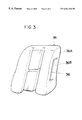
- FIG. 3 is a perspective view of the seat pad of the seat structure having a side impact air bag apparatus according to the first embodiment, as viewed diagonally from the front of the seat;
- FIG. 4 is a perspective view of a seat to which the seat structure having a side impact air bag apparatus according to the first embodiment is applied, as viewed diagonally from the front of the seat;
- FIG. 5 is a perspective view of the seat back frame of the seat structure having a side impact air bag apparatus according to a second embodiment of the present invention, as viewed diagonally from the rear of the seat;
- FIG. 6 is a horizontal cross-sectional view showing the side portion of the seat structure having a side impact air bag apparatus according to a second embodiment of the present invention.
- FIG. 7 is a horizontal cross-sectional view showing the side portion of a conventional seat structure having a side impact air bag apparatus
- FIG. 8 is a perspective view of the seat back frame of the conventional seat structure having a side impact air bag apparatus, as viewed diagonally from the front of the seat;
- FIG. 9 is a horizontal cross-sectional view showing the side portion of another conventional seat structure having a side impact air bag apparatus.
- a side impact air bag apparatus 14 having a box-like shape is disposed within a seat back 12 of a seat 10 . More specifically, the air bag apparatus 14 is disposed within a side portion 12 A formed at the outer side of the seat back 12 in the transverse direction of the vehicle such that the air bag apparatus 14 extends in the vertical direction.
- a seat back frame 16 of the seat back 12 has a pair of side frames 18 and 20 each serving as a reinforcing member and disposed at a corresponding widthwise end of the seat back frame 16 .
- the upper ends of the side frames 18 and 20 are connected to each other via an upper frame 22 which is formed of a tube material and is bent in a generally U-like shape.
- the edge portions of the side frames 18 and 22 located at the rear side of the seat are connected to each other via a plurality of seat wires 24 arranged in the longitudinal direction of the side frames 18 and 20 .
- a flange 18 A which is bent inward in the widthwise direction of the seat (i.e., in the direction IN).
- a flange 18 B which is bent inward in the widthwise direction of the seat.
- an air bag accommodating concave portion 26 At the central portion of the side frame 18 in the longitudinal direction of the vehicle is formed an air bag accommodating concave portion 26 .
- This air bag accommodating concave portion 26 is formed by depressing the central portion of the side frame 18 toward the inside of the seat in a predetermined region extending in the longitudinal direction of the seat back. At the rear end of the air bag accommodating concave portion 26 , the side frame 18 is further depressed toward the inside of the seat, thereby defining an inflator accommodating portion 26 A
- a folded air bag 28 is accommodated in the air bag accommodating concave portion 26 , and a cylindrical inflator 30 is accommodated in the inflator accommodating portion 26 A. Accordingly, the portion of the side frame 18 which forms the concave portion 26 serves as a bottom portion of an air bag case, and the air bag 28 is deployed by gas jetted from the inflator 30 .
- the air bag 28 is fixed to the side frame 18 by using fixing means such as, for example, two pieces of tape 32 and 34 provided at upper and lower portions of the side frame 18 . These pieces of tape 32 and 34 are easily peeled off from the side frame 18 when the air bag 28 is deployed.
- a U-shaped slit 38 is formed in the side pad portion 36 A of the seat pad 36 which covers the seat back frame.
- the U-shaped slit 38 is formed such that the slit 38 faces the peripheral portion of the air bag accommodating concave portion 26 (see FIG. 1 ), and the rear side of the portion surrounded by the U-shaped slit 38 closer to the back of the seat is continuous with the side pad portion 36 A.
- the portion surrounded by the slit 38 i.e., a lid portion 36 B serves as a lid of an air bag case. When the air bag 28 is deployed, the lid portion 36 B smoothly opens toward the outside of the seat.
- a seat surface layer 40 covers the outer face of the seat pad 36 .
- This seat surface layer 40 is made by sewing several covering sheets at seams 42 , 44 , 46 , etc., serving as sewn portions. Among these seams, the seam 44 faces the front edge portion of the side pad portion 36 A of the seat pad 36 . Therefore, when the air bag 28 is deployed, the seam 44 is broken so that the seat surface layer 40 can be easily ruptured there.
- the gas inflator 30 of the air bag apparatus 14 when the gas inflator 30 of the air bag apparatus 14 is operated upon occurrence of a side crash, gas is jetted from the gas inflator 30 .
- the air bag 28 is deployed from the side portion 12 A of the seat back 12 toward the front side of the seat, as indicated by an imaginary line in FIG. 1, so that the air bag 28 abuts a side portion of an occupant 40 on the seat 10 .
- the lid portion 36 B of the seat pad 36 is pressed by the air bag 28 so that it smoothly opens outward, as illustrated by an imaginary line in FIG. 1, and the seam 44 of the seat cover 40 is easily broken. Accordingly, the air bag 28 can be deployed quickly.
- the inflator 39 and the folded air bag 28 are accommodated within the air bag accommodating concave portion 26 , which is formed by depressing the side frame 18 inward in the widthwise direction of the seat, and the inflator 39 and the air bag 28 are covered together with the seat pad 36 by the seat surface layer 40 . Accordingly, the overall width of the seat back 12 becomes smaller compared to the case where an air bag apparatus is attached to the outer side surface of the side frame. This increases the room space in the vehicle.
- the seat structure of the present embodiment does not deteriorate the appearance of the seat 10 , and can be applied to seats of small vehicles.
- the portion of the side frame 18 which forms the air bag accommodating concave portion 26 serves as the bottom portion of an air bag case and the lid portion 36 B of the seat pad 36 serves as the lid portion of the air bag case, it is possible to eliminate a bracket for attaching the air bag apparatus to the side frame and an air bag case which have been used in conventional structures. Accordingly, the number of required parts can be decreased, and the assembly can be performed in a facilitated manner.
- FIGS. 5 and 6 a seat structure having a side impact air bag apparatus according to a second embodiment of the present invention will be described with reference to FIGS. 5 and 6.
- an inflator mounting opening 94 is formed in a side frame (reinforcing member) 92 of the seat back frame 16 such that the opening 94 runs in the longitudinal direction of the seat back.
- the electrical wire connected to an inflator 48 is led to the inside of the side frame 92 through the inflator mounting opening 94 .
- the inflator 48 together with the inflator accommodating portion 98 which projects toward the rear surface side of the air bag apparatus 96 , is inserted in the inflator mounting opening 94 so as to be nipped and so as project further toward the vehicle transverse direction inner side than the side frame 92 .
- the air bag apparatus 96 is directly fixed to the side frame 42 by the plurality of bolts 52 , which serve as the fixing means, being inserted from the seat back frame 16 transverse direction outer side into through-holes provided in the air bag apparatus 96 and the side frame 92 , and by the plurality of bolts 52 being screwed with nuts 54 which also serve as the fixing means.
- the air bag apparatus 96 as well as the seat pad 36 are covered by the seat surface layer 40 .
- a seam 100 which is located in the vicinity of the lid portion 36 B and serves as a sewn portion, is easily broken.
- the inflator 48 is fitted into the inflator mounting opening 94 such that the inflator 48 project inward from the side frame 92 in the transverse direction of the vehicle, and the electrical wire 50 of the inflator 48 is led to the inside of the side frame 92 through the inflator mounting opening 94 . Accordingly, it is unnecessary to separately provide a cover for protecting the electrical wire 50 , unlike the conventional structure shown in FIG. 9, in which a cover 152 is separately provided in the side portion 72 A of the seat back 72 so as to protect the electrical wire 50 .
- a portion 12 B rearwardly projecting from the side portion 12 A of the seat back 12 as indicated by an imaginary line in FIG. 6 can be made smaller, so that the freedom in designing can be increased. In addition, since the number of required parts decreases, the assembly can be performed more efficiently.
- the inflator 48 Since the inflator 48 is mounted such that it is fitted into the inflator mounting opening 94 and projects inward from the side frame 92 in the transverse direction of the vehicle, the inflator 48 can be supported with increased rigidly.
Abstract
Description
Claims (21)
Priority Applications (1)
| Application Number | Priority Date | Filing Date | Title |
|---|---|---|---|
| US09/389,056 US6561540B1 (en) | 1995-09-18 | 1999-09-02 | Seat structure having a side impact air bag apparatus |
Applications Claiming Priority (4)
| Application Number | Priority Date | Filing Date | Title |
|---|---|---|---|
| JP7-238489 | 1995-09-18 | ||
| JP07238489A JP3141747B2 (en) | 1995-09-18 | 1995-09-18 | Seat structure with side collision airbag device |
| US08/710,417 US6089594A (en) | 1995-09-18 | 1996-09-17 | Seat structure having a side impact air bag apparatus |
| US09/389,056 US6561540B1 (en) | 1995-09-18 | 1999-09-02 | Seat structure having a side impact air bag apparatus |
Related Parent Applications (1)
| Application Number | Title | Priority Date | Filing Date |
|---|---|---|---|
| US08/710,417 Division US6089594A (en) | 1995-09-18 | 1996-09-17 | Seat structure having a side impact air bag apparatus |
Publications (1)
| Publication Number | Publication Date |
|---|---|
| US6561540B1 true US6561540B1 (en) | 2003-05-13 |
Family
ID=17031012
Family Applications (2)
| Application Number | Title | Priority Date | Filing Date |
|---|---|---|---|
| US08/710,417 Expired - Lifetime US6089594A (en) | 1995-09-18 | 1996-09-17 | Seat structure having a side impact air bag apparatus |
| US09/389,056 Expired - Lifetime US6561540B1 (en) | 1995-09-18 | 1999-09-02 | Seat structure having a side impact air bag apparatus |
Family Applications Before (1)
| Application Number | Title | Priority Date | Filing Date |
|---|---|---|---|
| US08/710,417 Expired - Lifetime US6089594A (en) | 1995-09-18 | 1996-09-17 | Seat structure having a side impact air bag apparatus |
Country Status (4)
| Country | Link |
|---|---|
| US (2) | US6089594A (en) |
| EP (1) | EP0788941B1 (en) |
| JP (1) | JP3141747B2 (en) |
| DE (1) | DE69625170T2 (en) |
Cited By (38)
| Publication number | Priority date | Publication date | Assignee | Title |
|---|---|---|---|---|
| US20030146605A1 (en) * | 2002-02-07 | 2003-08-07 | Trw Occupant Restraint Systems Gmbh & Co. Kg | Vehicle seat with a gas bag module integrated in a back rest |
| FR2861351A1 (en) * | 2003-10-28 | 2005-04-29 | Cera | Vehicle interior component with cavity in foam body for airbag has textile sleeve extending along cavity walls and stuck to foam body |
| FR2861350A1 (en) * | 2003-10-28 | 2005-04-29 | Cera | Cab interior unit for use in motor vehicle seat, has air bag system exerting force on rigidifying band until tearable seam, during triggering of system, where rigidifying band extends from opening of housing to seam |
| US20070040362A1 (en) * | 2005-08-19 | 2007-02-22 | Lear Corporation | Vehicle seat frame structure and method of manufacturing same |
| US20070057493A1 (en) * | 2005-09-14 | 2007-03-15 | Recaro Gmbh & Co. Kg | Vehicle seat, in particular a sports seat |
| US20090315373A1 (en) * | 2008-06-24 | 2009-12-24 | Gm Global Technology Operations, Inc. | Vehicle Seat Side Air Bag |
| US20100244412A1 (en) * | 2009-03-27 | 2010-09-30 | Toyoda Gosei Co., Ltd. | Side airbag apparatus |
| US20130200599A1 (en) * | 2010-10-20 | 2013-08-08 | Toyota Jidosha Kabushiki Kaisha | Rear seat side airbag device |
| US8727374B1 (en) * | 2013-01-24 | 2014-05-20 | Ford Global Technologies, Llc | Vehicle seatback with side airbag deployment |
| US9434342B2 (en) | 2014-12-11 | 2016-09-06 | Toyota Jidosha Kabushiki Kaisha | Vehicle seat equipped with side airbag device |
| US9566930B2 (en) | 2015-03-02 | 2017-02-14 | Ford Global Technologies, Llc | Vehicle seat assembly with side-impact airbag deployment mechanism |
| US9649962B2 (en) | 2013-01-24 | 2017-05-16 | Ford Global Technologies, Llc | Independent cushion extension and thigh support |
| US9707870B2 (en) | 2013-01-24 | 2017-07-18 | Ford Global Technologies, Llc | Flexible seatback system |
| US9707873B2 (en) | 2013-01-24 | 2017-07-18 | Ford Global Technologies, Llc | Flexible seatback system |
| US9707917B2 (en) | 2013-11-27 | 2017-07-18 | Toyota Jidosha Kabushiki Kaisha | Vehicle seat |
| US9802512B1 (en) | 2016-04-12 | 2017-10-31 | Ford Global Technologies, Llc | Torsion spring bushing |
| US9834166B1 (en) | 2016-06-07 | 2017-12-05 | Ford Global Technologies, Llc | Side airbag energy management system |
| US9845029B1 (en) | 2016-06-06 | 2017-12-19 | Ford Global Technologies, Llc | Passive conformal seat with hybrid air/liquid cells |
| US9849817B2 (en) | 2016-03-16 | 2017-12-26 | Ford Global Technologies, Llc | Composite seat structure |
| US9849856B1 (en) | 2016-06-07 | 2017-12-26 | Ford Global Technologies, Llc | Side airbag energy management system |
| US9889773B2 (en) | 2016-04-04 | 2018-02-13 | Ford Global Technologies, Llc | Anthropomorphic upper seatback |
| US9914378B1 (en) | 2016-12-16 | 2018-03-13 | Ford Global Technologies, Llc | Decorative and functional upper seatback closeout assembly |
| US9994135B2 (en) | 2016-03-30 | 2018-06-12 | Ford Global Technologies, Llc | Independent cushion thigh support |
| US10046683B2 (en) | 2014-01-23 | 2018-08-14 | Ford Global Technologies, Llc | Suspension seat back and cushion system having an inner suspension panel |
| US10046682B2 (en) | 2015-08-03 | 2018-08-14 | Ford Global Technologies, Llc | Back cushion module for a vehicle seating assembly |
| US10065546B2 (en) | 2014-04-02 | 2018-09-04 | Ford Global Technologies, Llc | Vehicle seating assembly with manual independent thigh supports |
| US10166895B2 (en) | 2016-06-09 | 2019-01-01 | Ford Global Technologies, Llc | Seatback comfort carrier |
| US20190023216A1 (en) * | 2017-07-24 | 2019-01-24 | GM Global Technology Operations LLC | Seat assemblies including integrated airbag doors for motor vehicles |
| US10220737B2 (en) | 2016-04-01 | 2019-03-05 | Ford Global Technologies, Llc | Kinematic back panel |
| US10239431B2 (en) | 2016-09-02 | 2019-03-26 | Ford Global Technologies, Llc | Cross-tube attachment hook features for modular assembly and support |
| US10279714B2 (en) | 2016-08-26 | 2019-05-07 | Ford Global Technologies, Llc | Seating assembly with climate control features |
| US10286824B2 (en) | 2016-08-24 | 2019-05-14 | Ford Global Technologies, Llc | Spreader plate load distribution |
| US10286818B2 (en) | 2016-03-16 | 2019-05-14 | Ford Global Technologies, Llc | Dual suspension seating assembly |
| US10369905B2 (en) | 2014-10-03 | 2019-08-06 | Ford Global Technologies, Llc | Tuned flexible support member and flexible suspension features for comfort carriers |
| US10377279B2 (en) | 2016-06-09 | 2019-08-13 | Ford Global Technologies, Llc | Integrated decking arm support feature |
| US10391910B2 (en) | 2016-09-02 | 2019-08-27 | Ford Global Technologies, Llc | Modular assembly cross-tube attachment tab designs and functions |
| US10596936B2 (en) | 2017-05-04 | 2020-03-24 | Ford Global Technologies, Llc | Self-retaining elastic strap for vent blower attachment to a back carrier |
| US11458924B2 (en) | 2018-04-05 | 2022-10-04 | Adient Us Llc | Vehicle seat |
Families Citing this family (21)
| Publication number | Priority date | Publication date | Assignee | Title |
|---|---|---|---|---|
| JP3748285B2 (en) * | 1995-11-16 | 2006-02-22 | オートリブ デベロップメント アクテボラゲット | Side impact airbag device |
| FR2759957B1 (en) * | 1997-02-21 | 1999-04-30 | Peugeot | INTERCHANGEABLE MODULE FOR INFLATABLE PROTECTIVE BAG, FOR MOTOR VEHICLE SEAT |
| DE19746234A1 (en) * | 1997-10-20 | 1999-04-22 | Volkswagen Ag | Vehicle seat with airbag unit |
| DE29807644U1 (en) * | 1998-04-28 | 1998-07-02 | Trw Automotive Safety Sys Gmbh | Impact protection device |
| JP2001130363A (en) * | 1999-11-08 | 2001-05-15 | Daihatsu Motor Co Ltd | Side air bag device for automobile |
| DE10052942A1 (en) * | 2000-10-25 | 2002-05-16 | Takata Europa Vehicle Safety T | Safety device for motor vehicles |
| DE10137825C1 (en) * | 2001-08-02 | 2002-10-02 | Daimler Chrysler Ag | Modified headrest for vehicle seat fitted with crash protection airbag at side leaves gap for deployment of airbag and holds occupant's head at greater than minimum distance from airbag module |
| FR2830820B1 (en) * | 2001-10-11 | 2004-01-30 | Peugeot Citroen Automobiles Sa | MOTOR VEHICLE SEAT COMPRISING AN INFLATABLE BAG DEVICE HAVING A HOUSING FIXED ON A SIDE POST OF THE SEAT |
| GB2397047B (en) * | 2003-01-10 | 2006-02-22 | Autoliv Development Ab | Improvements in or relating to vehicle air-seats and air-bag units |
| DE10329245A1 (en) * | 2003-06-24 | 2005-02-03 | Takata-Petri (Ulm) Gmbh | Vehicle seat has airbag covered by seat cover having slit dividing cover into at least two adjacent sections with one separate from housing of airbag unit for faster deployment |
| FR2924992B1 (en) * | 2007-12-18 | 2010-10-22 | Faurecia Sieges Automobile | SEAT STRUCTURE AND ASSEMBLY COMPRISING A RECEPTION PORTION FOR GAS GENERATOR FOR INFLATABLE CUSHION |
| JP5408360B2 (en) * | 2010-09-14 | 2014-02-05 | トヨタ自動車株式会社 | Fixing structure of rear side airbag device for vehicle |
| JP5413523B2 (en) * | 2011-01-27 | 2014-02-12 | トヨタ自動車株式会社 | Car seat with side airbag device |
| DE102011117938A1 (en) * | 2011-11-08 | 2013-05-08 | GM Global Technology Operations LLC (n. d. Gesetzen des Staates Delaware) | Seat for seat assembly of motor car, has airbag module that is arranged on lateral side of seat back, and gas generator which is provided for inflating airbag |
| JP5692197B2 (en) * | 2012-10-10 | 2015-04-01 | トヨタ自動車株式会社 | Vehicle seat provided with side airbag device and method for assembling side airbag device to vehicle seat |
| US9211820B2 (en) | 2012-11-01 | 2015-12-15 | Graco Children's Products Inc. | Child safety seat with side impact energy redirection |
| JP6131826B2 (en) | 2013-10-30 | 2017-05-24 | トヨタ紡織株式会社 | Vehicle seat |
| DE102015203364B4 (en) | 2015-02-25 | 2021-03-18 | Lear Corporation | Seat cheek arrangement with an airbag |
| US10882430B2 (en) * | 2017-05-23 | 2021-01-05 | Toyota Boshoku Kabushiki Kaisha | Vehicle seat |
| JP6538783B2 (en) * | 2017-08-31 | 2019-07-03 | テイ・エス テック株式会社 | Vehicle seat |
| US10836287B1 (en) * | 2019-05-03 | 2020-11-17 | Ford Global Technologies, Llc | Vehicle seat |
Citations (18)
| Publication number | Priority date | Publication date | Assignee | Title |
|---|---|---|---|---|
| JPH0450052A (en) | 1990-06-18 | 1992-02-19 | Mazda Motor Corp | Seat structure for vehicle |
| US5112079A (en) | 1989-06-13 | 1992-05-12 | General Engineering (Netherlands ) B.V. | Arrangement for protecting an occupant of a vehicle |
| JPH04348712A (en) | 1991-05-27 | 1992-12-03 | Aisin Seiki Co Ltd | Seat back |
| US5222761A (en) | 1990-09-28 | 1993-06-29 | Ikeda Bussan Co., Ltd. | Airbag restraint system |
| US5251931A (en) | 1992-03-09 | 1993-10-12 | Trw Vehicle Safety Systems Inc. | Safety apparatus |
| US5348342A (en) | 1992-04-10 | 1994-09-20 | Ab Volvo | Air bag system for side collision protection |
| JPH07215159A (en) | 1994-02-07 | 1995-08-15 | Mazda Motor Corp | Vehicular air bag device |
| US5498030A (en) | 1995-03-28 | 1996-03-12 | General Motors Corporation | Air bag module |
| WO1996007563A1 (en) | 1994-09-08 | 1996-03-14 | Alliedsignal Deutschland Gmbh | Inflatable safety restraint for vehicle occupant protection |
| US5503428A (en) | 1995-02-03 | 1996-04-02 | Hoover Universal, Inc. | Vehicle seat with an inflatable air cushion |
| GB2296476A (en) | 1994-12-20 | 1996-07-03 | Ikeda Bussan Co | Vehicular seat with side air-bag vertically mounted in a cutout or groove in the seat side panel |
| US5556127A (en) | 1995-06-26 | 1996-09-17 | Takata, Inc. | Seat mounted side impact module |
| US5588671A (en) | 1995-09-21 | 1996-12-31 | Takata, Inc. | Resealable tear seam for seat deployed side impact air bag |
| US5601332A (en) | 1995-01-30 | 1997-02-11 | Hoover Universal, Inc. | Replaceable seat booster with an inflatable air cushion module |
| US5667243A (en) | 1996-02-29 | 1997-09-16 | General Motors Corporation | Air bag module |
| US5735572A (en) | 1997-01-16 | 1998-04-07 | Ford Global Technologies, Inc. | Vehicle seat back frame and airbag module assembly |
| US5816610A (en) | 1995-10-11 | 1998-10-06 | Toyota Jidosha Kabushiki Kaisha | Seat structure having a side impact air bag apparatus |
| US5826938A (en) | 1995-10-11 | 1998-10-27 | Araco Kabushiki Kaisha | Vehicle seat with side air bag assembly |
Family Cites Families (1)
| Publication number | Priority date | Publication date | Assignee | Title |
|---|---|---|---|---|
| US5238342A (en) * | 1993-01-06 | 1993-08-24 | Monogram Aerospace Industries, Inc. | Blind fastener with mechanical thread lock |
-
1995
- 1995-09-18 JP JP07238489A patent/JP3141747B2/en not_active Expired - Fee Related
-
1996
- 1996-09-17 DE DE69625170T patent/DE69625170T2/en not_active Expired - Lifetime
- 1996-09-17 US US08/710,417 patent/US6089594A/en not_active Expired - Lifetime
- 1996-09-17 EP EP96114893A patent/EP0788941B1/en not_active Expired - Lifetime
-
1999
- 1999-09-02 US US09/389,056 patent/US6561540B1/en not_active Expired - Lifetime
Patent Citations (19)
| Publication number | Priority date | Publication date | Assignee | Title |
|---|---|---|---|---|
| US5112079A (en) | 1989-06-13 | 1992-05-12 | General Engineering (Netherlands ) B.V. | Arrangement for protecting an occupant of a vehicle |
| JPH0450052A (en) | 1990-06-18 | 1992-02-19 | Mazda Motor Corp | Seat structure for vehicle |
| US5222761A (en) | 1990-09-28 | 1993-06-29 | Ikeda Bussan Co., Ltd. | Airbag restraint system |
| JPH04348712A (en) | 1991-05-27 | 1992-12-03 | Aisin Seiki Co Ltd | Seat back |
| US5251931A (en) | 1992-03-09 | 1993-10-12 | Trw Vehicle Safety Systems Inc. | Safety apparatus |
| US5348342A (en) | 1992-04-10 | 1994-09-20 | Ab Volvo | Air bag system for side collision protection |
| JPH07215159A (en) | 1994-02-07 | 1995-08-15 | Mazda Motor Corp | Vehicular air bag device |
| WO1996007563A1 (en) | 1994-09-08 | 1996-03-14 | Alliedsignal Deutschland Gmbh | Inflatable safety restraint for vehicle occupant protection |
| GB2296476A (en) | 1994-12-20 | 1996-07-03 | Ikeda Bussan Co | Vehicular seat with side air-bag vertically mounted in a cutout or groove in the seat side panel |
| US5651582A (en) | 1994-12-20 | 1997-07-29 | Ikeda Bussan Co., Ltd. | Vehicular seat with side air-bag |
| US5601332A (en) | 1995-01-30 | 1997-02-11 | Hoover Universal, Inc. | Replaceable seat booster with an inflatable air cushion module |
| US5503428A (en) | 1995-02-03 | 1996-04-02 | Hoover Universal, Inc. | Vehicle seat with an inflatable air cushion |
| US5498030A (en) | 1995-03-28 | 1996-03-12 | General Motors Corporation | Air bag module |
| US5556127A (en) | 1995-06-26 | 1996-09-17 | Takata, Inc. | Seat mounted side impact module |
| US5588671A (en) | 1995-09-21 | 1996-12-31 | Takata, Inc. | Resealable tear seam for seat deployed side impact air bag |
| US5816610A (en) | 1995-10-11 | 1998-10-06 | Toyota Jidosha Kabushiki Kaisha | Seat structure having a side impact air bag apparatus |
| US5826938A (en) | 1995-10-11 | 1998-10-27 | Araco Kabushiki Kaisha | Vehicle seat with side air bag assembly |
| US5667243A (en) | 1996-02-29 | 1997-09-16 | General Motors Corporation | Air bag module |
| US5735572A (en) | 1997-01-16 | 1998-04-07 | Ford Global Technologies, Inc. | Vehicle seat back frame and airbag module assembly |
Cited By (46)
| Publication number | Priority date | Publication date | Assignee | Title |
|---|---|---|---|---|
| US7178826B2 (en) * | 2002-02-07 | 2007-02-20 | Trw Occupant Restraint Systems Gmbh & Co Kg | Vehicle seat with a gas bag module integrated in a back rest |
| US20030146605A1 (en) * | 2002-02-07 | 2003-08-07 | Trw Occupant Restraint Systems Gmbh & Co. Kg | Vehicle seat with a gas bag module integrated in a back rest |
| FR2861351A1 (en) * | 2003-10-28 | 2005-04-29 | Cera | Vehicle interior component with cavity in foam body for airbag has textile sleeve extending along cavity walls and stuck to foam body |
| FR2861350A1 (en) * | 2003-10-28 | 2005-04-29 | Cera | Cab interior unit for use in motor vehicle seat, has air bag system exerting force on rigidifying band until tearable seam, during triggering of system, where rigidifying band extends from opening of housing to seam |
| US7866689B2 (en) * | 2005-08-19 | 2011-01-11 | Lear Corporation | Vehicle seat frame structure and method of manufacturing same |
| US20070040362A1 (en) * | 2005-08-19 | 2007-02-22 | Lear Corporation | Vehicle seat frame structure and method of manufacturing same |
| US20070057493A1 (en) * | 2005-09-14 | 2007-03-15 | Recaro Gmbh & Co. Kg | Vehicle seat, in particular a sports seat |
| US20090315373A1 (en) * | 2008-06-24 | 2009-12-24 | Gm Global Technology Operations, Inc. | Vehicle Seat Side Air Bag |
| US7695064B2 (en) | 2008-06-24 | 2010-04-13 | Gm Global Technology Operations, Inc. | Vehicle seat side air bag |
| US8226113B2 (en) * | 2009-03-27 | 2012-07-24 | Toyoda Gosei Co., Ltd. | Side airbag apparatus |
| US20100244412A1 (en) * | 2009-03-27 | 2010-09-30 | Toyoda Gosei Co., Ltd. | Side airbag apparatus |
| US20130200599A1 (en) * | 2010-10-20 | 2013-08-08 | Toyota Jidosha Kabushiki Kaisha | Rear seat side airbag device |
| US8651518B2 (en) * | 2010-10-20 | 2014-02-18 | Toyota Jidosha Kabushiki Kaisha | Rear seat side airbag device |
| US9873360B2 (en) | 2013-01-24 | 2018-01-23 | Ford Global Technologies, Llc | Flexible seatback system |
| US8727374B1 (en) * | 2013-01-24 | 2014-05-20 | Ford Global Technologies, Llc | Vehicle seatback with side airbag deployment |
| US9649962B2 (en) | 2013-01-24 | 2017-05-16 | Ford Global Technologies, Llc | Independent cushion extension and thigh support |
| US9707870B2 (en) | 2013-01-24 | 2017-07-18 | Ford Global Technologies, Llc | Flexible seatback system |
| US9707873B2 (en) | 2013-01-24 | 2017-07-18 | Ford Global Technologies, Llc | Flexible seatback system |
| US9873362B2 (en) | 2013-01-24 | 2018-01-23 | Ford Global Technologies, Llc | Flexible seatback system |
| US9707917B2 (en) | 2013-11-27 | 2017-07-18 | Toyota Jidosha Kabushiki Kaisha | Vehicle seat |
| US10046683B2 (en) | 2014-01-23 | 2018-08-14 | Ford Global Technologies, Llc | Suspension seat back and cushion system having an inner suspension panel |
| US10065546B2 (en) | 2014-04-02 | 2018-09-04 | Ford Global Technologies, Llc | Vehicle seating assembly with manual independent thigh supports |
| US10369905B2 (en) | 2014-10-03 | 2019-08-06 | Ford Global Technologies, Llc | Tuned flexible support member and flexible suspension features for comfort carriers |
| US9434342B2 (en) | 2014-12-11 | 2016-09-06 | Toyota Jidosha Kabushiki Kaisha | Vehicle seat equipped with side airbag device |
| US9566930B2 (en) | 2015-03-02 | 2017-02-14 | Ford Global Technologies, Llc | Vehicle seat assembly with side-impact airbag deployment mechanism |
| US10040415B2 (en) | 2015-03-02 | 2018-08-07 | Ford Global Technologies, Llc | Vehicle seat assembly with side-impact airbag deployment mechanism |
| US10046682B2 (en) | 2015-08-03 | 2018-08-14 | Ford Global Technologies, Llc | Back cushion module for a vehicle seating assembly |
| US9849817B2 (en) | 2016-03-16 | 2017-12-26 | Ford Global Technologies, Llc | Composite seat structure |
| US10286818B2 (en) | 2016-03-16 | 2019-05-14 | Ford Global Technologies, Llc | Dual suspension seating assembly |
| US9994135B2 (en) | 2016-03-30 | 2018-06-12 | Ford Global Technologies, Llc | Independent cushion thigh support |
| US10220737B2 (en) | 2016-04-01 | 2019-03-05 | Ford Global Technologies, Llc | Kinematic back panel |
| US9889773B2 (en) | 2016-04-04 | 2018-02-13 | Ford Global Technologies, Llc | Anthropomorphic upper seatback |
| US9802512B1 (en) | 2016-04-12 | 2017-10-31 | Ford Global Technologies, Llc | Torsion spring bushing |
| US9845029B1 (en) | 2016-06-06 | 2017-12-19 | Ford Global Technologies, Llc | Passive conformal seat with hybrid air/liquid cells |
| US9834166B1 (en) | 2016-06-07 | 2017-12-05 | Ford Global Technologies, Llc | Side airbag energy management system |
| US9849856B1 (en) | 2016-06-07 | 2017-12-26 | Ford Global Technologies, Llc | Side airbag energy management system |
| US10166895B2 (en) | 2016-06-09 | 2019-01-01 | Ford Global Technologies, Llc | Seatback comfort carrier |
| US10377279B2 (en) | 2016-06-09 | 2019-08-13 | Ford Global Technologies, Llc | Integrated decking arm support feature |
| US10286824B2 (en) | 2016-08-24 | 2019-05-14 | Ford Global Technologies, Llc | Spreader plate load distribution |
| US10279714B2 (en) | 2016-08-26 | 2019-05-07 | Ford Global Technologies, Llc | Seating assembly with climate control features |
| US10239431B2 (en) | 2016-09-02 | 2019-03-26 | Ford Global Technologies, Llc | Cross-tube attachment hook features for modular assembly and support |
| US10391910B2 (en) | 2016-09-02 | 2019-08-27 | Ford Global Technologies, Llc | Modular assembly cross-tube attachment tab designs and functions |
| US9914378B1 (en) | 2016-12-16 | 2018-03-13 | Ford Global Technologies, Llc | Decorative and functional upper seatback closeout assembly |
| US10596936B2 (en) | 2017-05-04 | 2020-03-24 | Ford Global Technologies, Llc | Self-retaining elastic strap for vent blower attachment to a back carrier |
| US20190023216A1 (en) * | 2017-07-24 | 2019-01-24 | GM Global Technology Operations LLC | Seat assemblies including integrated airbag doors for motor vehicles |
| US11458924B2 (en) | 2018-04-05 | 2022-10-04 | Adient Us Llc | Vehicle seat |
Also Published As
| Publication number | Publication date |
|---|---|
| JPH0976859A (en) | 1997-03-25 |
| EP0788941A3 (en) | 1999-12-08 |
| US6089594A (en) | 2000-07-18 |
| EP0788941B1 (en) | 2002-12-04 |
| DE69625170D1 (en) | 2003-01-16 |
| JP3141747B2 (en) | 2001-03-05 |
| EP0788941A2 (en) | 1997-08-13 |
| DE69625170T2 (en) | 2003-07-17 |
Similar Documents
| Publication | Publication Date | Title |
|---|---|---|
| US6561540B1 (en) | Seat structure having a side impact air bag apparatus | |
| US5651582A (en) | Vehicular seat with side air-bag | |
| EP1034989B1 (en) | Vehicle seat with an air bag deployment apparatus | |
| US6341797B1 (en) | Air bag device for side collision of automobile | |
| US5944341A (en) | Air bag apparatus for vehicle | |
| EP0842064B1 (en) | Air bag apparatus for seat of vehicle | |
| US6450528B1 (en) | Vehicle seat housing an airbag device | |
| US5636862A (en) | Air bag assembly with tether | |
| US5498030A (en) | Air bag module | |
| EP0818364B1 (en) | Airbag module with deployment chute | |
| EP0804353B1 (en) | Side impact soft pack air bag module | |
| JP3385852B2 (en) | Vehicle airbag device | |
| US5890734A (en) | Integral cover-deployment chute for side airbag module | |
| JPH09132102A (en) | Air bag device of vehicular seat | |
| WO1999056991A1 (en) | Airbag surround for seamless instrument panel | |
| US5816660A (en) | Vehicle seat side air bag trim closeout assembly | |
| JP3528704B2 (en) | Vehicle seat with built-in airbag device | |
| JP3097489B2 (en) | Seat-mounted side airbag device | |
| JPH09323609A (en) | Automobile seat with air bag device | |
| JP3303695B2 (en) | Vehicle seat structure with side airbag device | |
| JPH09290702A (en) | Air bag device | |
| JP3385853B2 (en) | Vehicle airbag device | |
| JP2856123B2 (en) | Seat structure with side collision airbag | |
| JPH09315254A (en) | Air bag device for car seat | |
| JP3414028B2 (en) | Arrangement structure of airbag device |
Legal Events
| Date | Code | Title | Description |
|---|---|---|---|
| AS | Assignment |
Owner name: TOYOTA JIDOSHA KABUSHIKI KAISHA, JAPAN Free format text: ASSIGNMENT OF ASSIGNORS INTEREST;ASSIGNORS:HASEGAWA, YASUNORI;KATO, HISAAKI;OHNO, MITSUYOSHI;AND OTHERS;REEL/FRAME:010222/0673 Effective date: 19960830 |
|
| STCF | Information on status: patent grant |
Free format text: PATENTED CASE |
|
| FEPP | Fee payment procedure |
Free format text: PAYER NUMBER DE-ASSIGNED (ORIGINAL EVENT CODE: RMPN); ENTITY STATUS OF PATENT OWNER: LARGE ENTITY Free format text: PAYOR NUMBER ASSIGNED (ORIGINAL EVENT CODE: ASPN); ENTITY STATUS OF PATENT OWNER: LARGE ENTITY |
|
| FPAY | Fee payment |
Year of fee payment: 4 |
|
| FPAY | Fee payment |
Year of fee payment: 8 |
|
| FPAY | Fee payment |
Year of fee payment: 12 |