US6569600B2 - Optical recording material - Google Patents
Optical recording material Download PDFInfo
- Publication number
- US6569600B2 US6569600B2 US09/822,057 US82205701A US6569600B2 US 6569600 B2 US6569600 B2 US 6569600B2 US 82205701 A US82205701 A US 82205701A US 6569600 B2 US6569600 B2 US 6569600B2
- Authority
- US
- United States
- Prior art keywords
- reactant
- optical recording
- recording material
- sensitizer
- substituted
- Prior art date
- Legal status (The legal status is an assumption and is not a legal conclusion. Google has not performed a legal analysis and makes no representation as to the accuracy of the status listed.)
- Expired - Fee Related, expires
Links
Classifications
-
- G—PHYSICS
- G11—INFORMATION STORAGE
- G11B—INFORMATION STORAGE BASED ON RELATIVE MOVEMENT BETWEEN RECORD CARRIER AND TRANSDUCER
- G11B7/00—Recording or reproducing by optical means, e.g. recording using a thermal beam of optical radiation by modifying optical properties or the physical structure, reproducing using an optical beam at lower power by sensing optical properties; Record carriers therefor
- G11B7/24—Record carriers characterised by shape, structure or physical properties, or by the selection of the material
- G11B7/241—Record carriers characterised by shape, structure or physical properties, or by the selection of the material characterised by the selection of the material
- G11B7/242—Record carriers characterised by shape, structure or physical properties, or by the selection of the material characterised by the selection of the material of recording layers
- G11B7/244—Record carriers characterised by shape, structure or physical properties, or by the selection of the material characterised by the selection of the material of recording layers comprising organic materials only
-
- G—PHYSICS
- G11—INFORMATION STORAGE
- G11B—INFORMATION STORAGE BASED ON RELATIVE MOVEMENT BETWEEN RECORD CARRIER AND TRANSDUCER
- G11B7/00—Recording or reproducing by optical means, e.g. recording using a thermal beam of optical radiation by modifying optical properties or the physical structure, reproducing using an optical beam at lower power by sensing optical properties; Record carriers therefor
- G11B2007/0003—Recording, reproducing or erasing systems characterised by the structure or type of the carrier
- G11B2007/0009—Recording, reproducing or erasing systems characterised by the structure or type of the carrier for carriers having data stored in three dimensions, e.g. volume storage
-
- G—PHYSICS
- G11—INFORMATION STORAGE
- G11B—INFORMATION STORAGE BASED ON RELATIVE MOVEMENT BETWEEN RECORD CARRIER AND TRANSDUCER
- G11B7/00—Recording or reproducing by optical means, e.g. recording using a thermal beam of optical radiation by modifying optical properties or the physical structure, reproducing using an optical beam at lower power by sensing optical properties; Record carriers therefor
- G11B7/004—Recording, reproducing or erasing methods; Read, write or erase circuits therefor
- G11B7/0065—Recording, reproducing or erasing by using optical interference patterns, e.g. holograms
-
- Y—GENERAL TAGGING OF NEW TECHNOLOGICAL DEVELOPMENTS; GENERAL TAGGING OF CROSS-SECTIONAL TECHNOLOGIES SPANNING OVER SEVERAL SECTIONS OF THE IPC; TECHNICAL SUBJECTS COVERED BY FORMER USPC CROSS-REFERENCE ART COLLECTIONS [XRACs] AND DIGESTS
- Y10—TECHNICAL SUBJECTS COVERED BY FORMER USPC
- Y10S—TECHNICAL SUBJECTS COVERED BY FORMER USPC CROSS-REFERENCE ART COLLECTIONS [XRACs] AND DIGESTS
- Y10S430/00—Radiation imagery chemistry: process, composition, or product thereof
- Y10S430/146—Laser beam
-
- Y—GENERAL TAGGING OF NEW TECHNOLOGICAL DEVELOPMENTS; GENERAL TAGGING OF CROSS-SECTIONAL TECHNOLOGIES SPANNING OVER SEVERAL SECTIONS OF THE IPC; TECHNICAL SUBJECTS COVERED BY FORMER USPC CROSS-REFERENCE ART COLLECTIONS [XRACs] AND DIGESTS
- Y10—TECHNICAL SUBJECTS COVERED BY FORMER USPC
- Y10T—TECHNICAL SUBJECTS COVERED BY FORMER US CLASSIFICATION
- Y10T428/00—Stock material or miscellaneous articles
- Y10T428/21—Circular sheet or circular blank
Definitions
- This invention relates to an optical recording element which is capable of storing and retrieving information.
- CD and DVD disks represent successful high volume data storage technologies.
- One major advantage of these technologies is that reading or writing of data is accomplished by shining light on the disk so there is no physical contact between the media and the optical head.
- the total storage capacity of these disks is limited by the size of the smallest marks on the surface of the media that can be read by the wavelength of light employed.
- Many attempts have been made to develop data storage systems with progressively smaller marks.
- the required equipment is prohibitively expensive, and the data access rates tend to be unacceptably slow.
- One way to increase the storage capacity of a medium is to record the information depthwise, rather than just on the surface.
- Bleaching and photoreactions e.g., photochromicity
- organic dyes has also been used as a means to record optical data, both in a single layer in writeable CD-type media, and depthwise (dissolved in a bulk piece of polymer).
- photoreactions e.g., photochromicity
- a large amount of optical power is required in these systems to produce readable marks, therefore the rate of recording of such media is slow.
- photochromic systems also tend to fade over time.
- Holographic recording has also been achieved by optically induced birefringence in suitable polymers, a process which relies on photo-alignment of the side chains within the polymers. Once again, a large amount of optical power is required, and this process is inefficient and slow. In addition, the fidelity of the recorded information may degrade with time since optically induced orientation tends to relax over time in polymers.
- JP 2000-086588 discloses a recording medium using changes in circular dichroism based on the interconversion of chiral norbornadiene and quadricyclane derivatives.
- this technique requires enantiomerically enriched compounds that are difficult to synthesize.
- this application does not disclose the use of sensitizers for photoinduced electron transfer.
- U.S. Pat. No. 5,759,721 discloses a holographic recording medium which uses a photopolymerization technique which can also be used for recording information optically in three dimensions.
- photopolymerization is usually accompanied by shrinkage of the material which is a consequence of the process of forming new chemical bonds among the constituents. Any dimensional changes that occur on writing limit the resolution that can be achieved, and reduce the data capacity of the medium.
- photopolymerization generally requires the use of low molecular weight reactants so that media made from these materials tend to be undesirably soft or sticky.
- free radical polymerization is subject to interference by atmospheric oxygen which causes undesirable inconsistencies in the process.
- an optical recording material which when exposed to actinic radiation produces a change in optical properties in the exposed regions, thereby providing a pattern of intelligence for storing and retrieving information
- the recording material comprising:
- a sensitizer capable of absorbing actinic radiation to cause an initial one electron oxidation of the reactant.
- an optical recording material is obtained which possesses several advantages over the prior art.
- the invention involves a photoinitiated chain reaction in a solid polymer that creates changes in the optical properties of the material.
- our invention relies on photoisomerization rather than photopolymerization, the dimensional changes accompanying recording are negligible. (No new bonds are formed between molecules.)
- the invention involves a recording process that is efficient in the use of light. Because the process involves a photoinitiated chain reaction, many new molecules are formed per photon absorbed (chemical amplification). A relatively large change in optical properties is obtained with only a small exposure to the recording beam.
- the material of the invention is a simple, stable polymer, which can be conveniently fabricated into films and slabs.
- the optical changes in the material of the invention are large, permanent, localized, and can easily be detected, forming the basis for an optical storage medium.
- the invention is especially suited to three dimensional optical data recording systems such as holography and two-photon optics.
- cation radical rearrangements of the invention are not sensitive to molecular oxygen, and will not be subject to the inconsistent performance which is commonly observed for free radical photopolymerizations that are currently used in the art.
- Suitable binders include a monomeric glass as defined in U.S. Pat. Nos. 4,499,165 and 4,626,361, the disclosures of which are hereby incorporated by reference, such as sucrose octaacetate; or a polymeric material such as, for example, poly(alkyl methacrylate), poly(alkyl acrylate), polystyrene, polycarbonate, cellulose acetate or poly(vinyl butyral).
- the binder should be optically transparent in the spectral region where the sensitizer absorbs, i.e., should not have significant absorption at the excitation wavelengths, and should not interfere with the chemical transformation of the reactant.
- the binder may also contain a plasticizer, a preservative, etc.
- the optical recording element of the invention may be in the form of a self-supporting slab or disk. It may also be coated on a support such as poly(ethylene terephthalate), poly(ethylene naphthoate), polystyrene, cellulose acetate, inorganic supports such as glass, quartz, silicon, etc. In a preferred embodiment, the support is a polyester or glass.
- the surface of the substrate may be treated in order to improve the adhesion of the recording layer to the support.
- the surface may be corona discharge treated prior to applying the optical recording material.
- an under-coating or subbing layer such as a layer formed from a halogenated phenol or a partially hydrolyzed vinyl chloride-vinyl acetate copolymer, can be applied to the surface of the support.
- the recording layer thickness may range from about 1 ⁇ m to about 1 cm, preferably from about 100 ⁇ m to about 1000 ⁇ m.
- the reactant used in the invention is capable of undergoing a chemical transformation upon a one electron oxidation, thus causing the change in optical properties in the exposed regions of the optical recording material.
- Such compounds undergo a photoinduced cation radical rearrangement to product species, a process which defines the recording event.
- product formation there are accompanying changes in optical characteristics such as refractive index, fluorescence properties, or absorption spectrum. No new chemical bonds are formed between individual reactant molecules, therefore, there are negligible dimensional changes in the media during the recording event.
- the reactant is usually present in a relatively high concentration.
- the reactant comprises from about 1 to about 50% by weight of said material
- the sensitizer comprises from about 0.001 to about 10% by weight of the material, with the balance being binder.
- the chemical transformation of the reactant is an isomerization including reactions such as cyclizations, cycloadditions and cycloreversions.
- reactions such as cyclizations, cycloadditions and cycloreversions.
- General examples of such transformations are the interconversion between 1a and 1b or 2a and 2b.
- R in the formulas above and below can be H; a substituted or unsubstituted alkyl or alkoxy group having from about 1 to about 12 carbon atoms, preferably 1-3 carbon atoms, such as methyl, ethyl, isopropyl, butyl, etc; a cyano or a carboxylate group; a substituted or unsubstituted aryl group having from about 6 to about 18 carbon atoms, such as phenyl, naphthyl, phenanthryl, anthryl, etc.; a substituted or unsubstituted heteroaromatic group such as furyl, thienyl, pyridyl, benzofuryl, benzotbienyl, etc.
- Substituents on the aryl or heteroaryl groups include, for example, one or more alkyl, aryl, alkoxyl, aryloxyl, thioalkyl, thioaryl groups etc.
- substituents R can be joined together to form additional ring systems.
- Examples of 1a/1b are:
- Examples of 2a/2b are:
- the reactant is selected so that its oxidation potential is less than that of its product, and that a suitably rapid isomerization can occur upon electron transfer to the sensitizer (see below).
- the compounds listed above possess these characteristics, but there may exist other (as yet unidentified) molecules that share the same properties, and that would function equally well or better than those listed.
- the sensitizer used in the invention initiates the chemical transformation of the reactant.
- the sensitizer must be capable of oxidizing the reactant to a radical cation after the sensitizer has absorbed light (i.e., photoinduced electron transfer).
- light i.e., photoinduced electron transfer
- the sensitizer upon absorption of the actinic radiation is capable of accepting an electron from the reactant.
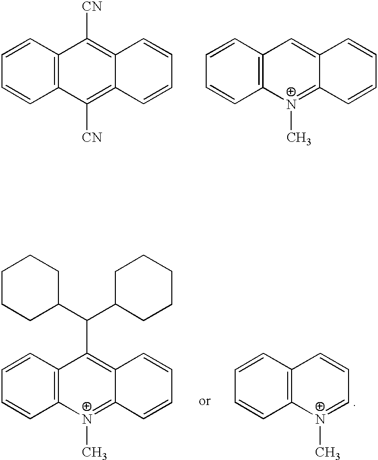
- Examples of such sensitizers include those shown in Tables 2 and 3.
- the sensitizer upon absorption of said actinic radiation fragments gives an oxidant capable of accepting an electron from the reactant.
- Examples of such sensitizers include those shown in Table 4.
- reaction energetics may be used. There are three controlling parameters in reaction energetics: the excitation energy (E S* ) and the reduction potential (E S red ) of the sensitizing electron acceptor (S) and the oxidation potential (E R ox ) of the reactant (R), an electron donor.
- E S* excitation energy
- E S red reduction potential
- E R ox oxidation potential
- the energy of the excited state should be higher or only slightly lower than the energy stored in the primary product, the radical ion pair, S ⁇ * R +* .
- the excitation energy of the sensitizer is conveniently determined from the midpoint of the normalized absorption and emission spectrum of S, if the reaction proceeds from the singlet excited state. However, if the reaction proceeds via the triplet state, then the triplet energy of S should be used as the excitation energy.
- E IP The energy of the radical ion pair, is given by Eq. 1, where ⁇ is an energy increment that depends on the medium polarity and ranges from nearly zero in highly polar media to ca. 0.3 eV in the least polar media.
- polar solvents such as acetonitrile or methylene chloride
- the energy increment ⁇ in Eq. 1 is expected to be near the maximum value, i.e., in the range of 0.2 to 0.3 eV.
- sensitizing electron acceptors with excitation energy equal to or larger than the difference between the oxidation potential of the reactant and the reduction potential of the acceptor, (E R ox ⁇ E S red ), will satisfy the energetic requirements of photoinitiating the reaction, Eq. 2.
- the algebraic sum of the excitation energy of the sensitizer and its reduction potential should be approximately equal to or larger than the oxidation potential of the reactant.
- hexamethyldewarbenzene which has an oxidation potential of 1.59 V vs. SCE
- numerous sensitizing acceptors which meet the requirement of Eq. 3, can be used.
- Table 2 are some of the compounds that meet the requirements, namely having the sum of excitation energy plus reduction potential that is equal to or exceeds 1.59 eV, and are therefore useful with hexamethyldewarbenzene reactant.
- derivatives from many different compounds can be used as electron accepting sensitizers for various reactants, provided that the energetic requirements discussed above are satisfied.
- potential sensitizers include: cyanoaromatics such as 1-cyanonaphthalene, 1,4-dicyanonaphthalene, 9,10-dicyanoanthracene, 2,9,10-tricyanoanthracene, 2,6,9,10-tetracyanoanthracene, aromatic anhydrides and imides such as 1,8-naphthylene dicarboxylic, 1,4,6,8-naphthalene tetracarboxylic, 3,4-perylene dicarboxylic, and 3,4,9,10-perylene tetracarboxylic anhydride or imide; condensed pyridinium salts such as quinolinium, isoquinolinium, phenanthridinium, acridinium salts; and pyryllium salts.
- sensitizers that involve the triplet excited state are carbonyl compounds such as quinones such as benzo-, naphtho-, anthro-quinones with electron withdrawing substituents (e.g., chloro and cyano). Ketocoumarins especially those with strong electron withdrawing moieties such as pyridinium can also be used as sensitizers.
- sensitizers examples are shown in Table 3. These sensitizers can optionally contain substituents such as methyl, ethyl, tertiary butyl, phenyl, methoxy, chloro, etc. that may be included to modify properties such as solubility, absorption spectrum, reduction potential, etc.
- the sensitizer upon absorption of actinic radiation reacts to produce a fragment radical cation, the fragment radical cation then accepts an electron from the reactant, whereby the oxidation potential of the neutral fragment is greater than that of the reactant.
- a magnetically stirred suspension of 6.16 g (46 mmol) of AlCl 3 and 30 mL freshly distilled CH 2 Cl 2 was cooled in an ice water bath.
- 5.0 g (92 mmol) of 2-butyne in 15 mL CH 2 Cl 2 was added over 20 minutes.
- the resulting solution was stirred for an addition 30 minutes after the addition was complete.
- This solution of the tetramethylcyclobutadiene aluminum chloride complex was transferred to another flask, which contained a stirred solution of 5.90 g (34 mmol) of ethyl phenylpropiolate in 30 mL CH 2 Cl 2 in an ice water bath, via a double tipped needle under positive nitrogen pressure.
- a heavy-walled glass tube was charged with ethyl phenylpropiolate (5.0 g, 29 mmol), 2.85 g (43 mmol) of freshly distilled cyclopentadiene, 5 mL of xylenes, and 20 mg of 3,3′-di-t-butyl-4,4′-dihydroxy-6,6′-dimethyl diphenyl sulfide, and sealed under argon. The tube was heated for 48 h at 175° C., and then cooled.
- Ethyl 2-phenylnorbornadiene-1-carboxylate (1.24 g, 5.2 mmol) was dissolved in 50 mL of acetonitrile and irradiated in a Rayonet photochemical reactor using 350 nm light for 24 h at room temperature to produce ethyl 2-phenylquadricyclane-1-carboxylate in quantitative yield.
- the product was characterized by NMR.
- the intermediate product (3.10 g, 15 mmol) was dissolved in 60 mL of acetonitrile and placed in a tall glass tube. This solution was irradiated in a Rayonet photochemical reactor for 108 h with UV light of wavelength 340-360 nm. After the solvent was removed, the product was obtained as a gold oil.
- 1 H NMR (CDCl 3 ) ⁇ 2.15 (m, 1 H), 2.33 (m, 3 H), 2.50 (m, 2 H), 3.68 (s, 6 H).
- the intermediate product 2,3-diphenylnorbornadiene was prepared as follows: A solution of 2,3-bis(tert-butylsulfonyl)norbornadiene (prepared according to the procedure of Riera, et al. Tetrahedron Letters 1990, volume 31, page 2173) (5.50 g, 19 mmol) in dry tetrahydrofuran (50 mL) was treated with 95 mmol of phenyl lithium at ⁇ 78° C. under an argon atmosphere. After allowing the reaction mixture to gradually warm to room temperature overnight, methanol (25 mL) was added, and the solution was partially concentrated at reduced pressure.
- 2,3-Diphenylnorbornadiene (0.50 g, 2.0 mmol) was dissolved in 25 mL of chloroform, deaerated by bubbling nitrogen through the solution for 5 minutes, and placed in a tall glass tube. This solution was irradiated in a Rayonet photochemical reactor for 18 h with UV light of wavelength 340-360 nm. After the solvent was removed, the product 1,5-diphenyl quadricyclane was obtained as a tan oil.
- 1 H NMR (CDCl 3 ) ⁇ 1.89 (m, 2 H), 2.20 (m, 2 H), 2.42 (m, 1 H), 7.0-7-2 (m, 10 H).
- This element is the same as Optical Recording Element 1 except that the sensitizer was S-26.
- This element is the same as Optical Recording Element 1 except that the sensitizer was S-4.
- An experimental apparatus consisting of a UV interferometer to write a holographic grating in a sample element and a rotation stage and probe beam to measure the angular spectrum of the grating.
- the light source for the UV interferometer was an argon-ion laser beam at a wavelength of 3507 ⁇ . This laser beam was spatially filtered with a 10 ⁇ UV microscope objective and a 5 ⁇ m pinhole before being collimated in a 7.5 mm diameter beam by a 50 mm focal length fused silica lens. This UV beam defined the optical axis of the apparatus.
- a phase mask with a period of 1070 nm dispersed the UV beam according to the grating equation. The zero-order beam was blocked so that it could not reach the sample plane.
- the first-order diffracted beams which define the plane of incidence, each propagated away from the grating at an angle of 19.15° with respect to the optical axis.
- Two plane mirrors positioned approximately 23 cm. from the phase mask as measured along the optical axis, directed the first-order diffracted beams to the film plane where they intersected at an angle of 32.19°.
- the sample plane was positioned 50 cm. from the phase mask, as measured along the optical axis.
- the optical axis was normal to the film plane and bisected the 32.19° angle made by the interfering UV beams.
- the fringe pattern formed by the interfering UV beams was sinusoidal with a period of 633 nm.
- the light source for the probe beam was a helium-neon laser beam at a wavelength of 6328 ⁇ .
- the probe beam was polarized perpendicularly to the plane of incidence. This laser beam was spatially filtered with a 10 ⁇ microscope objective and a 25 ⁇ m pinhole before being collimated in a 3.0 mm diameter beam by a 5 ⁇ microscope objective.
- the probe beam was modulated at 1400 Hz by a chopper wheel so that a lock-in amplifier could be used for low noise detection.
- the probe beam intersected the sample plane at an angle of 30.00° with respect to the optical axis. This angle satisfied the Bragg condition for maximum diffraction efficiency.
- the sample was mounted on a rotation stage so that the diffraction efficiency of the holographic grating could be measured as a function of angular detuning from the Bragg angle.
- a measurement of the exposure characteristics of a sample element began with an alignment check of the apparatus.
- a microscope slide was placed in the sample plane and the back-reflections from its surface were used to verify that the sample plane was normal to the optical axis, that the probe beam was incident at 30.00°, that the UV beams were intersecting at an angle of 32.19°, and that the optical axis bisected the angle made by the UV beams.
- the argon-ion laser power was adjusted such that the power in each of the interfering UV beams was 3.0 mW.
- the power of the probe beam was measured in Volts by the lock-in amplifier so that the diffraction efficiency measurements could be normalized.
- the writing procedure was as follows. The UV beams were blocked with a shutter while the sample was clamped in position. The apparatus was allowed to relax for a minimum of 60 sec so that the mechanical and thermal disturbances caused by the alignment procedure could decay. The sample was then exposed to the interfering UV beams for a predetermined length of time while a computer recorded the power of the diffracted probe beam. At the end of the exposure, the UV beams were blocked and the power of the diffracted probe beam was measured as a function of angular detuning from the Bragg angle. From these two sets of data, the angular spectrum of the grating, diffraction efficiency vs. time, and index modulation vs. time curves could be generated. The results are listed below.
- the exposure to the recording beam as described above creates a diffraction grating in the material due to the creation of a pattern of refractive index changes.
- the diffraction efficiency listed in the tables below is a measurement of the pattern of refractive index change recorded and any number greater than zero is desirable.
- the procedure was identical to Optical Recording Procedure 1, except that a Krypton ion laser was employed, with an output wavelength of 406 nm, and the power in each of the interfering beams was 8 mW.
- the results are listed below.
- sensitizers S-2, S-26 and S-4 are all effective sensitizers for the isomerization reaction.
- This element was the same as Optical Recording Element 1 except that the binder was Bisphenol A polycarbonate.
- This element was prepared the same as Optical Recording Element 1 except that the reactant was ethyl pentamethyldewarbenzoate (R-2).
- This element was prepared the same as Optical Recording Element 1 except that the reactant was 2-phenyl-3,4,5,6-tetraamethyldewarbenzoate (R-3).
- This element was prepared the same as Optical Recording Element 1 except that the reactant was ethyl 2-phenylquadricyclane-1-carboxylate (R-8)
- This element was prepared the same as Optical Recording Element 1 except that the reactant was 3,4-diphenyl-1,2-cyclobutanedicarboxylic acid, cyclic trimethylene ester (R-12), which was prepared by the procedure of Freedman, et al. (Organic Preparations and Procedures International, 1969, volume 1, page 267).
- This element was prepared the same as Optical Recording Element 1 except that the reactant was 2,5-dimethyl-3,4-diphenyl-pentacyclo[4.4.0.02,5.03,8.04,7]decane) (R-13), which was prepared by the procedure of Hasegawa, et al. (Journal of Organic Chemistry, volume 56, page 2170).
- This element was prepared the same as Optical Recording Element 1 except that the reactant was 2,3-diphenylquadricyclane (R-10), and the amount of reactant employed was 5 wt. %.
- This element was prepared the same as Optical Recording Element 1 except that the reactant was ethyl 2-phenyl-3,4,5,6-tetraamethyldewarbenzoate (R-3).
- This element was prepared the same as Optical Recording Element 1 except that the reactant was ethyl 2-(4-methoxyphenyl)-3,4,5,6-tetraamethyldewarbenzoate (R-5).
- This element was prepared the same as Optical Recording Element 2 except that the amount of reactant employed was 5 wt. % and the sensitizer was S-25.
- This element was prepared the same as Optical Recording Element 6 except that no reactant was used and the amount of sensitizer employed was doubled.
- This element was prepared the same as Optical Recording Element 6 except that no sensitizer was used.
- the diffraction efficiency of Optical Recording Element 1 was measured and found to be 0.118%. After storing the element at 22° C. for 106 days, the diffraction efficiency was remeasured and found to be 0.115%. The results show that a permanent, stable pattern of refractive index change can be recorded.
Abstract
Description


| TABLE 1 | ||
| Reactants | ||
| R-1 |
 |
||
| R-2 |
 |
||
| R-3 |
 |
||
| R-4 |
 |
||
| R-5 |
 |
||
| R-6 |
 |
||
| R-7 |
 |
||
| R-8 |
 |
||
| R-9 |
 |
||
| R-10 |
 |
||
| R-11 |
 |
||
| R-12 |
 |
||
| R-13 |
 |
||

| TABLE 2 | ||||
| Electron Transfer Sensitizers | ES* | ES red | ||
| S-1 |
 |
3.85 | −1.88 |
| S-2 |
 |
2.90 | −0.91 |
| S-3 |
 |
3.53 | −0.85 |
| S-4 |
 |
2.77 | −0.48 |
| S-5 |
 |
2.84 | −0.40 |
| TABLE 3 | ||
| Electron Transfer Sensitizers | ||
| S-6 |
 |
||
| S-7 |
 |
||
| S-8 |
 |
||
| S-9 |
 |
||
| S-10 |
 |
||
| S-11 |
 |
||
| S-13 |
 |
||
| S-14 |
 |
||
| S-15 |
 |
||
| S-16 |
 |
||
| S-17 |
 |
||
| S-18 |
 |
||
| S-19 |
 |
||
| S-20 |
 |
||
| S-21 |
 |
||
| S-22 |
 |
||
| S-23 |
 |
||
| S-24 |
 |
||

| TABLE 4 | ||
| Radical Cation-Generating Sensitizers | ||
| S-25 |
 |
| S-26 |
 |
| S-27 |
 |
| S-28 |
 |
| S-29 |
 |
| S-30 |
 |
| Where R = alkyl, substituted alkyl, aryl, or acyl. | |
| TABLE 5 | ||||||
| Optical | Diffrac- | |||||
| Optical | Optical | density at | tion | Width of | ||
| Record- | Record- | recording | Effi- | Angular | Change in | |
| ing | ing | wave- | Time | ciency | Spectrum | Refractive |
| Element | Procedure | length | (sec) | (%) | (deg.) | Index |
| 1 | 1 | 0.14 | 10 | 0.023 | ||
| 1 | 1 | 0.14 | 40 | 0.081 | ||
| 1 | 1 | 0.14 | 150 | 0.170 | 4.2 | 4.8 × 10⁻⁴ |
| 2 | 1 | 0.20 | 10 | 0.019 | ||
| 2 | 1 | 0.20 | 40 | 0.035 | 7.5 | 2.2 × 10⁻⁴ |
| 3 | 1 | 0.26 | 10 | 0.010 | ||
| 3 | 1 | 0.26 | 40 | 0.023 | ||
| 3 | 1 | 0.26 | 100 | 0.034 | 6.5 | 2.2 × 10⁻⁴ |
| TABLE 6 | ||||||
| Optical | Diffrac- | |||||
| Optical | Optical | density at | tion | Width of | ||
| Record- | Record- | recording | Effi- | Angular | Change in | |
| ing | ing | wave- | Time | ciency | Spectrum | Refractive |
| Element | Procedure | length | (sec) | (%) | (deg.) | Index |
| 1 | 1 | 0.14 | 10 | 0.023 | ||
| 1 | 1 | 0.14 | 40 | 0.081 | ||
| 1 | 1 | 0.14 | 150 | 0.170 | 4.2 | 4.8 × 10⁻⁴ |
| 4 | 1 | 0.06 | 10 | 0.0048 | ||
| 4 | 1 | 0.06 | 40 | 0.021 | ||
| 4 | 1 | 0.06 | 150 | 0.051 | ||
| 4 | 1 | 0.06 | 250 | 0.060 | 7.4 | 2.9 × 10⁻⁴ |
| TABLE 7 | ||||||
| Optical | Diffrac- | |||||
| Optical | Optical | density at | tion | Width of | ||
| Record- | Record- | recording | Effi- | Angular | Change in | |
| ing | ing | wave- | Time | ciency | Spectrum | Refractive |
| Element | Procedure | length | (sec) | (%) | (deg.) | Index |
| 1 | 1 | 0.14 | 10 | 0.023 | ||
| 1 | 1 | 0.14 | 40 | 0.081 | ||
| 1 | 1 | 0.14 | 150 | 0.170 | 4.2 | 4.8 × 10⁻⁴ |
| 5 | 3 | 0.20 | 20 | 0.66 | ||
| 6 | 2 | 0.20 | 240 | 0.57 | ||
| 6 | 3 | 0.20 | 20 | 1.1 | ||
| 7 | 2 | 0.20 | 15 | 0.09 | ||
| 8 | 2 | 0.20 | 0.0015 | |||
| 9 | 1 | 0.08 | 10 | 0.00076 | ||
| 9 | 1 | 0.08 | 40 | 0.0016 | ||
| 9 | 1 | 0.08 | 150 | 0.0025 | 4.8 | 5.7 × 10⁻⁵ |
| 10 | 2 | 0.20 | 15 | 0.020 | ||
| 11 | 2 | 0.20 | 240 | 0.024 | ||
| 12 | 2 | 0.20 | 240 | 0.0020 | ||
| TABLE 8 | |||||
| Optical | Diffraction | ||||
| Optical Recording | Recording | Time | Efficiency | ||
| Element | Procedure | (min/) | (%) | ||
| 13 | 1 | 20 | 0.094 | ||
| C-1 | 1 | 30 | 0 | ||
| C-2 | 1 | 30 | 0 | ||
Claims (19)


Priority Applications (3)
| Application Number | Priority Date | Filing Date | Title |
|---|---|---|---|
| US09/822,057 US6569600B2 (en) | 2001-03-30 | 2001-03-30 | Optical recording material |
| EP02076044A EP1246179A3 (en) | 2001-03-30 | 2002-03-18 | Optical recording material |
| JP2002094797A JP2002318433A (en) | 2001-03-30 | 2002-03-29 | Optical recording material |
Applications Claiming Priority (1)
| Application Number | Priority Date | Filing Date | Title |
|---|---|---|---|
| US09/822,057 US6569600B2 (en) | 2001-03-30 | 2001-03-30 | Optical recording material |
Publications (2)
| Publication Number | Publication Date |
|---|---|
| US20030072250A1 US20030072250A1 (en) | 2003-04-17 |
| US6569600B2 true US6569600B2 (en) | 2003-05-27 |
Family
ID=25235004
Family Applications (1)
| Application Number | Title | Priority Date | Filing Date |
|---|---|---|---|
| US09/822,057 Expired - Fee Related US6569600B2 (en) | 2001-03-30 | 2001-03-30 | Optical recording material |
Country Status (3)
| Country | Link |
|---|---|
| US (1) | US6569600B2 (en) |
| EP (1) | EP1246179A3 (en) |
| JP (1) | JP2002318433A (en) |
Cited By (5)
| Publication number | Priority date | Publication date | Assignee | Title |
|---|---|---|---|---|
| US20040038146A1 (en) * | 2002-08-19 | 2004-02-26 | Eastman Kodak Company | Optical recording material |
| US20050095390A1 (en) * | 2003-11-04 | 2005-05-05 | Eastman Kodak Company | In-situ polymerized matrix for isomerized optical recording article |
| US20050136357A1 (en) * | 2003-12-19 | 2005-06-23 | Farid Samir Y. | Optical recording media with triplet-sensitzed isomerization |
| US20090104561A1 (en) * | 2007-10-19 | 2009-04-23 | Hawker Craig J | High performance, crosslinked polymeric material for holographic data storage |
| US20100035176A1 (en) * | 2008-08-11 | 2010-02-11 | Robello Douglas R | Imaging element and method using differential light scattering |
Families Citing this family (6)
| Publication number | Priority date | Publication date | Assignee | Title |
|---|---|---|---|---|
| US8119041B2 (en) * | 2001-09-05 | 2012-02-21 | Fujifilm Corporation | Non-resonant two-photon absorption induction method and process for emitting light thereby |
| JP4683553B2 (en) * | 2005-11-21 | 2011-05-18 | 株式会社リコー | Light source unit, light detection unit, optical pickup device, and optical disk device |
| WO2007125937A1 (en) * | 2006-04-28 | 2007-11-08 | Mitsubishi Chemical Corporation | Photoreactive composition, optical material, optical recording material, volume hologram recording material, optical recording medium, and optical recording method therefor |
| US8778568B2 (en) * | 2010-12-14 | 2014-07-15 | General Electric Company | Optical data storage media and methods for using the same |
| CN104798134B (en) * | 2012-11-19 | 2017-06-09 | 日立民用电子株式会社 | Device for optical information recording, optical information recording/reproducing device, light information recording method, optical information recording/reproducing method and optical element |
| US9822320B1 (en) * | 2015-03-31 | 2017-11-21 | The United States Of America As Represented By The Secretary Of The Navy | Hybrid metallized organic fuels |
Citations (9)
| Publication number | Priority date | Publication date | Assignee | Title |
|---|---|---|---|---|
| US3658526A (en) * | 1969-08-25 | 1972-04-25 | Du Pont | Hologram recording in photopolymerizable layers |
| US4298678A (en) * | 1980-08-14 | 1981-11-03 | E. I. Du Pont De Nemours And Company | Photosensitive compositions and elements containing substituted hydroxylamine |
| US4491432A (en) * | 1982-12-30 | 1985-01-01 | International Business Machines Corporation | Chemical heat amplification in thermal transfer printing |
| US4707430A (en) * | 1983-10-13 | 1987-11-17 | Hiroshi Ozawa | Optical recording medium |
| US4780393A (en) * | 1986-01-25 | 1988-10-25 | Hoechst Aktiengesellschaft | Photopolymerizable composition and photopolymerizable recording material containing same |
| US5185233A (en) * | 1986-04-11 | 1993-02-09 | Canon Kabushiki Kaisha | Method of optical recording employing free radicals |
| US5759721A (en) | 1995-10-06 | 1998-06-02 | Polaroid Corporation | Holographic medium and process for use thereof |
| JP2000086588A (en) | 1998-09-14 | 2000-03-28 | Japan Science & Technology Corp | Norbonadiene-quadricyclane derivative and optical recording medium |
| US6221536B1 (en) * | 1998-07-01 | 2001-04-24 | Lucent Technologies Inc. | Material exhibiting compensation for polymerization-induced shrinkage and recording medium formed therefrom |
Family Cites Families (5)
| Publication number | Priority date | Publication date | Assignee | Title |
|---|---|---|---|---|
| US4693915A (en) * | 1984-04-20 | 1987-09-15 | Canon Kabushiki Kaisha | Film forming method, recording medium formed thereby and recording method therewith |
| JPH04195738A (en) * | 1990-11-26 | 1992-07-15 | Sanyo Electric Co Ltd | Optical recording medium, optical recording method, and optical recorder |
| JP3243864B2 (en) * | 1992-11-24 | 2002-01-07 | ソニー株式会社 | Photosensitive recording material |
| US5645964A (en) * | 1993-08-05 | 1997-07-08 | Kimberly-Clark Corporation | Digital information recording media and method of using same |
| JP2000248274A (en) * | 1999-03-01 | 2000-09-12 | Daikin Ind Ltd | Material for storing light energy and converting light energy to thermal energy |
-
2001
- 2001-03-30 US US09/822,057 patent/US6569600B2/en not_active Expired - Fee Related
-
2002
- 2002-03-18 EP EP02076044A patent/EP1246179A3/en not_active Withdrawn
- 2002-03-29 JP JP2002094797A patent/JP2002318433A/en active Pending
Patent Citations (9)
| Publication number | Priority date | Publication date | Assignee | Title |
|---|---|---|---|---|
| US3658526A (en) * | 1969-08-25 | 1972-04-25 | Du Pont | Hologram recording in photopolymerizable layers |
| US4298678A (en) * | 1980-08-14 | 1981-11-03 | E. I. Du Pont De Nemours And Company | Photosensitive compositions and elements containing substituted hydroxylamine |
| US4491432A (en) * | 1982-12-30 | 1985-01-01 | International Business Machines Corporation | Chemical heat amplification in thermal transfer printing |
| US4707430A (en) * | 1983-10-13 | 1987-11-17 | Hiroshi Ozawa | Optical recording medium |
| US4780393A (en) * | 1986-01-25 | 1988-10-25 | Hoechst Aktiengesellschaft | Photopolymerizable composition and photopolymerizable recording material containing same |
| US5185233A (en) * | 1986-04-11 | 1993-02-09 | Canon Kabushiki Kaisha | Method of optical recording employing free radicals |
| US5759721A (en) | 1995-10-06 | 1998-06-02 | Polaroid Corporation | Holographic medium and process for use thereof |
| US6221536B1 (en) * | 1998-07-01 | 2001-04-24 | Lucent Technologies Inc. | Material exhibiting compensation for polymerization-induced shrinkage and recording medium formed therefrom |
| JP2000086588A (en) | 1998-09-14 | 2000-03-28 | Japan Science & Technology Corp | Norbonadiene-quadricyclane derivative and optical recording medium |
Non-Patent Citations (3)
| Title |
|---|
| Gassman, Paul G., "Strained Hydrocabons" in "Photoinduced Electron Transfer, Part C. Photoinduced Electron Transfer Reactions:Organic Substrates", Chapter 4.2 pp. 70-87 (1988). * |
| Machine translation of JP 2000-086588.* * |
| Renge et al., "Inhomogeneous Broadening and pressure shifts of the optical spectra in organic glasses at low temperatures", J. Luminesc., vol. 86 (2000) pp. 241-247.* * |
Cited By (10)
| Publication number | Priority date | Publication date | Assignee | Title |
|---|---|---|---|---|
| US20040038146A1 (en) * | 2002-08-19 | 2004-02-26 | Eastman Kodak Company | Optical recording material |
| US6969578B2 (en) * | 2002-08-19 | 2005-11-29 | Eastman Kodak Company | Optical recording material |
| US20050095390A1 (en) * | 2003-11-04 | 2005-05-05 | Eastman Kodak Company | In-situ polymerized matrix for isomerized optical recording article |
| US7022392B2 (en) * | 2003-11-04 | 2006-04-04 | Eastman Kodak Company | In-situ polymerized matrix for isomerized optical recording article |
| US20050136357A1 (en) * | 2003-12-19 | 2005-06-23 | Farid Samir Y. | Optical recording media with triplet-sensitzed isomerization |
| US7459263B2 (en) | 2003-12-19 | 2008-12-02 | Eastman Kodak Company | Optical recording media with triplet-sensitized isomerization |
| US20090104561A1 (en) * | 2007-10-19 | 2009-04-23 | Hawker Craig J | High performance, crosslinked polymeric material for holographic data storage |
| US8187770B2 (en) * | 2007-10-19 | 2012-05-29 | The Regents Of The University Of California | High performance, crosslinked polymeric material for holographic data storage |
| US20100035176A1 (en) * | 2008-08-11 | 2010-02-11 | Robello Douglas R | Imaging element and method using differential light scattering |
| US8119328B2 (en) | 2008-08-11 | 2012-02-21 | Eastman Kodak Company | Imaging element and method using differential light scattering |
Also Published As
| Publication number | Publication date |
|---|---|
| EP1246179A3 (en) | 2003-11-12 |
| JP2002318433A (en) | 2002-10-31 |
| EP1246179A2 (en) | 2002-10-02 |
| US20030072250A1 (en) | 2003-04-17 |
Similar Documents
| Publication | Publication Date | Title |
|---|---|---|
| Lukyanov et al. | Spiropyrans: synthesis, properties, and application. | |
| US6267913B1 (en) | Two-photon or higher-order absorbing optical materials and methods of use | |
| US6969578B2 (en) | Optical recording material | |
| WO1998021521A1 (en) | Two-photon or higher-order absorbing optical materials and methods of use | |
| CA1247862A (en) | Binder-mixtures for optical recording layers and elements | |
| US6569600B2 (en) | Optical recording material | |
| JP5679627B2 (en) | Compositions and methods for holographic data storage | |
| US7459263B2 (en) | Optical recording media with triplet-sensitized isomerization | |
| EP2601556A1 (en) | Photorefractive composition responsive to multiple laser wavelengths across the visible light spectrum | |
| EP0502506B1 (en) | A photochromic material and an optical storage medium using the same | |
| EP0344891A2 (en) | Tetraazaporphin, process for producing the same, as well as optical recording media using the same and production processes thereof | |
| JPS62124986A (en) | Optical recording medium | |
| JP2000112074A (en) | Optical recording material and optical recording medium using the same | |
| KR100257893B1 (en) | Organic optical recording medium | |
| JPH05204102A (en) | Photomemory element and recording method therefor | |
| JPS60192691A (en) | Recording medium | |
| JPS613794A (en) | Optical information recording medium | |
| JPS63119036A (en) | Optical recording medium | |
| JPH09208560A (en) | Optical recording material | |
| Barachevsky | Organic storage media for holographic optical memory: State-of-the-art and future | |
| JPH0816199B2 (en) | Naphthoquinone methide compounds | |
| JPH0313382A (en) | Optical recording medium | |
| JPH0291076A (en) | Photochromic compound and production thereof | |
| JPS62233288A (en) | Optical information recording medium | |
| Sun et al. | Two-photon-induced fluorescence of diarylethene molecule |
Legal Events
| Date | Code | Title | Description |
|---|---|---|---|
| AS | Assignment |
Owner name: EASTMAN KODAK COMPANY, NEW YORK Free format text: ASSIGNMENT OF ASSIGNORS INTEREST;ASSIGNORS:DINNOCENZO, JOSEPH P.;FARID, SAMIR Y.;ROBELLO, DOUGLAS R.;AND OTHERS;REEL/FRAME:011705/0680;SIGNING DATES FROM 20010329 TO 20010330 |
|
| CC | Certificate of correction | ||
| FEPP | Fee payment procedure |
Free format text: PAYOR NUMBER ASSIGNED (ORIGINAL EVENT CODE: ASPN); ENTITY STATUS OF PATENT OWNER: LARGE ENTITY |
|
| FPAY | Fee payment |
Year of fee payment: 4 |
|
| FPAY | Fee payment |
Year of fee payment: 8 |
|
| AS | Assignment |
Owner name: CITICORP NORTH AMERICA, INC., AS AGENT, NEW YORK Free format text: SECURITY INTEREST;ASSIGNORS:EASTMAN KODAK COMPANY;PAKON, INC.;REEL/FRAME:028201/0420 Effective date: 20120215 |
|
| AS | Assignment |
Owner name: WILMINGTON TRUST, NATIONAL ASSOCIATION, AS AGENT, Free format text: PATENT SECURITY AGREEMENT;ASSIGNORS:EASTMAN KODAK COMPANY;PAKON, INC.;REEL/FRAME:030122/0235 Effective date: 20130322 Owner name: WILMINGTON TRUST, NATIONAL ASSOCIATION, AS AGENT, MINNESOTA Free format text: PATENT SECURITY AGREEMENT;ASSIGNORS:EASTMAN KODAK COMPANY;PAKON, INC.;REEL/FRAME:030122/0235 Effective date: 20130322 |
|
| AS | Assignment |
Owner name: BANK OF AMERICA N.A., AS AGENT, MASSACHUSETTS Free format text: INTELLECTUAL PROPERTY SECURITY AGREEMENT (ABL);ASSIGNORS:EASTMAN KODAK COMPANY;FAR EAST DEVELOPMENT LTD.;FPC INC.;AND OTHERS;REEL/FRAME:031162/0117 Effective date: 20130903 Owner name: BARCLAYS BANK PLC, AS ADMINISTRATIVE AGENT, NEW YORK Free format text: INTELLECTUAL PROPERTY SECURITY AGREEMENT (SECOND LIEN);ASSIGNORS:EASTMAN KODAK COMPANY;FAR EAST DEVELOPMENT LTD.;FPC INC.;AND OTHERS;REEL/FRAME:031159/0001 Effective date: 20130903 Owner name: JPMORGAN CHASE BANK, N.A., AS ADMINISTRATIVE, DELAWARE Free format text: INTELLECTUAL PROPERTY SECURITY AGREEMENT (FIRST LIEN);ASSIGNORS:EASTMAN KODAK COMPANY;FAR EAST DEVELOPMENT LTD.;FPC INC.;AND OTHERS;REEL/FRAME:031158/0001 Effective date: 20130903 Owner name: BARCLAYS BANK PLC, AS ADMINISTRATIVE AGENT, NEW YO Free format text: INTELLECTUAL PROPERTY SECURITY AGREEMENT (SECOND LIEN);ASSIGNORS:EASTMAN KODAK COMPANY;FAR EAST DEVELOPMENT LTD.;FPC INC.;AND OTHERS;REEL/FRAME:031159/0001 Effective date: 20130903 Owner name: JPMORGAN CHASE BANK, N.A., AS ADMINISTRATIVE, DELA Free format text: INTELLECTUAL PROPERTY SECURITY AGREEMENT (FIRST LIEN);ASSIGNORS:EASTMAN KODAK COMPANY;FAR EAST DEVELOPMENT LTD.;FPC INC.;AND OTHERS;REEL/FRAME:031158/0001 Effective date: 20130903 Owner name: PAKON, INC., NEW YORK Free format text: RELEASE OF SECURITY INTEREST IN PATENTS;ASSIGNORS:CITICORP NORTH AMERICA, INC., AS SENIOR DIP AGENT;WILMINGTON TRUST, NATIONAL ASSOCIATION, AS JUNIOR DIP AGENT;REEL/FRAME:031157/0451 Effective date: 20130903 Owner name: EASTMAN KODAK COMPANY, NEW YORK Free format text: RELEASE OF SECURITY INTEREST IN PATENTS;ASSIGNORS:CITICORP NORTH AMERICA, INC., AS SENIOR DIP AGENT;WILMINGTON TRUST, NATIONAL ASSOCIATION, AS JUNIOR DIP AGENT;REEL/FRAME:031157/0451 Effective date: 20130903 |
|
| REMI | Maintenance fee reminder mailed | ||
| LAPS | Lapse for failure to pay maintenance fees | ||
| STCH | Information on status: patent discontinuation |
Free format text: PATENT EXPIRED DUE TO NONPAYMENT OF MAINTENANCE FEES UNDER 37 CFR 1.362 |
|
| FP | Lapsed due to failure to pay maintenance fee |
Effective date: 20150527 |
|
| AS | Assignment |
Owner name: KODAK PHILIPPINES, LTD., NEW YORK Free format text: RELEASE BY SECURED PARTY;ASSIGNOR:JP MORGAN CHASE BANK, N.A., AS ADMINISTRATIVE AGENT;REEL/FRAME:049814/0001 Effective date: 20190617 Owner name: PAKON, INC., NEW YORK Free format text: RELEASE BY SECURED PARTY;ASSIGNOR:JP MORGAN CHASE BANK, N.A., AS ADMINISTRATIVE AGENT;REEL/FRAME:049814/0001 Effective date: 20190617 Owner name: QUALEX, INC., NEW YORK Free format text: RELEASE BY SECURED PARTY;ASSIGNOR:JP MORGAN CHASE BANK, N.A., AS ADMINISTRATIVE AGENT;REEL/FRAME:049814/0001 Effective date: 20190617 Owner name: KODAK AVIATION LEASING LLC, NEW YORK Free format text: RELEASE BY SECURED PARTY;ASSIGNOR:JP MORGAN CHASE BANK, N.A., AS ADMINISTRATIVE AGENT;REEL/FRAME:049814/0001 Effective date: 20190617 Owner name: CREO MANUFACTURING AMERICA LLC, NEW YORK Free format text: RELEASE BY SECURED PARTY;ASSIGNOR:JP MORGAN CHASE BANK, N.A., AS ADMINISTRATIVE AGENT;REEL/FRAME:049814/0001 Effective date: 20190617 Owner name: FPC, INC., NEW YORK Free format text: RELEASE BY SECURED PARTY;ASSIGNOR:JP MORGAN CHASE BANK, N.A., AS ADMINISTRATIVE AGENT;REEL/FRAME:049814/0001 Effective date: 20190617 Owner name: KODAK PORTUGUESA LIMITED, NEW YORK Free format text: RELEASE BY SECURED PARTY;ASSIGNOR:JP MORGAN CHASE BANK, N.A., AS ADMINISTRATIVE AGENT;REEL/FRAME:049814/0001 Effective date: 20190617 Owner name: KODAK IMAGING NETWORK, INC., NEW YORK Free format text: RELEASE BY SECURED PARTY;ASSIGNOR:JP MORGAN CHASE BANK, N.A., AS ADMINISTRATIVE AGENT;REEL/FRAME:049814/0001 Effective date: 20190617 Owner name: KODAK REALTY, INC., NEW YORK Free format text: RELEASE BY SECURED PARTY;ASSIGNOR:JP MORGAN CHASE BANK, N.A., AS ADMINISTRATIVE AGENT;REEL/FRAME:049814/0001 Effective date: 20190617 Owner name: NPEC, INC., NEW YORK Free format text: RELEASE BY SECURED PARTY;ASSIGNOR:JP MORGAN CHASE BANK, N.A., AS ADMINISTRATIVE AGENT;REEL/FRAME:049814/0001 Effective date: 20190617 Owner name: LASER PACIFIC MEDIA CORPORATION, NEW YORK Free format text: RELEASE BY SECURED PARTY;ASSIGNOR:JP MORGAN CHASE BANK, N.A., AS ADMINISTRATIVE AGENT;REEL/FRAME:049814/0001 Effective date: 20190617 Owner name: KODAK AMERICAS, LTD., NEW YORK Free format text: RELEASE BY SECURED PARTY;ASSIGNOR:JP MORGAN CHASE BANK, N.A., AS ADMINISTRATIVE AGENT;REEL/FRAME:049814/0001 Effective date: 20190617 Owner name: EASTMAN KODAK COMPANY, NEW YORK Free format text: RELEASE BY SECURED PARTY;ASSIGNOR:JP MORGAN CHASE BANK, N.A., AS ADMINISTRATIVE AGENT;REEL/FRAME:049814/0001 Effective date: 20190617 Owner name: FAR EAST DEVELOPMENT LTD., NEW YORK Free format text: RELEASE BY SECURED PARTY;ASSIGNOR:JP MORGAN CHASE BANK, N.A., AS ADMINISTRATIVE AGENT;REEL/FRAME:049814/0001 Effective date: 20190617 Owner name: KODAK (NEAR EAST), INC., NEW YORK Free format text: RELEASE BY SECURED PARTY;ASSIGNOR:JP MORGAN CHASE BANK, N.A., AS ADMINISTRATIVE AGENT;REEL/FRAME:049814/0001 Effective date: 20190617 |
|
| AS | Assignment |
Owner name: FPC INC., NEW YORK Free format text: RELEASE BY SECURED PARTY;ASSIGNOR:BARCLAYS BANK PLC;REEL/FRAME:052773/0001 Effective date: 20170202 Owner name: KODAK AMERICAS LTD., NEW YORK Free format text: RELEASE BY SECURED PARTY;ASSIGNOR:BARCLAYS BANK PLC;REEL/FRAME:052773/0001 Effective date: 20170202 Owner name: NPEC INC., NEW YORK Free format text: RELEASE BY SECURED PARTY;ASSIGNOR:BARCLAYS BANK PLC;REEL/FRAME:052773/0001 Effective date: 20170202 Owner name: QUALEX INC., NEW YORK Free format text: RELEASE BY SECURED PARTY;ASSIGNOR:BARCLAYS BANK PLC;REEL/FRAME:052773/0001 Effective date: 20170202 Owner name: KODAK PHILIPPINES LTD., NEW YORK Free format text: RELEASE BY SECURED PARTY;ASSIGNOR:BARCLAYS BANK PLC;REEL/FRAME:052773/0001 Effective date: 20170202 Owner name: KODAK REALTY INC., NEW YORK Free format text: RELEASE BY SECURED PARTY;ASSIGNOR:BARCLAYS BANK PLC;REEL/FRAME:052773/0001 Effective date: 20170202 Owner name: FAR EAST DEVELOPMENT LTD., NEW YORK Free format text: RELEASE BY SECURED PARTY;ASSIGNOR:BARCLAYS BANK PLC;REEL/FRAME:052773/0001 Effective date: 20170202 Owner name: EASTMAN KODAK COMPANY, NEW YORK Free format text: RELEASE BY SECURED PARTY;ASSIGNOR:BARCLAYS BANK PLC;REEL/FRAME:052773/0001 Effective date: 20170202 Owner name: KODAK (NEAR EAST) INC., NEW YORK Free format text: RELEASE BY SECURED PARTY;ASSIGNOR:BARCLAYS BANK PLC;REEL/FRAME:052773/0001 Effective date: 20170202 Owner name: LASER PACIFIC MEDIA CORPORATION, NEW YORK Free format text: RELEASE BY SECURED PARTY;ASSIGNOR:BARCLAYS BANK PLC;REEL/FRAME:052773/0001 Effective date: 20170202 |