US6571532B1 - Continuous motion case packing apparatus and method - Google Patents
Continuous motion case packing apparatus and method Download PDFInfo
- Publication number
- US6571532B1 US6571532B1 US09/301,394 US30139499A US6571532B1 US 6571532 B1 US6571532 B1 US 6571532B1 US 30139499 A US30139499 A US 30139499A US 6571532 B1 US6571532 B1 US 6571532B1
- Authority
- US
- United States
- Prior art keywords
- articles
- gripper
- pick
- article
- spring
- Prior art date
- Legal status (The legal status is an assumption and is not a legal conclusion. Google has not performed a legal analysis and makes no representation as to the accuracy of the status listed.)
- Expired - Fee Related
Links
- 230000033001 locomotion Effects 0.000 title claims abstract description 80
- 238000012856 packing Methods 0.000 title claims abstract description 79
- 238000000034 method Methods 0.000 title description 30
- 230000007246 mechanism Effects 0.000 claims abstract description 93
- 238000012546 transfer Methods 0.000 claims abstract description 89
- 241000237858 Gastropoda Species 0.000 claims abstract description 30
- 230000004323 axial length Effects 0.000 claims abstract description 10
- 239000011159 matrix material Substances 0.000 claims abstract description 8
- 230000000717 retained effect Effects 0.000 claims abstract description 6
- 239000007787 solid Substances 0.000 claims description 9
- 230000006835 compression Effects 0.000 claims description 8
- 238000007906 compression Methods 0.000 claims description 8
- 230000001360 synchronised effect Effects 0.000 claims description 5
- 238000009434 installation Methods 0.000 claims description 3
- 230000002159 abnormal effect Effects 0.000 claims description 2
- 238000000429 assembly Methods 0.000 abstract description 13
- 230000000712 assembly Effects 0.000 abstract description 13
- 238000012545 processing Methods 0.000 abstract description 4
- 210000003739 neck Anatomy 0.000 description 19
- 125000004122 cyclic group Chemical group 0.000 description 13
- 238000010276 construction Methods 0.000 description 6
- 241000282472 Canis lupus familiaris Species 0.000 description 5
- 230000001133 acceleration Effects 0.000 description 5
- 238000000151 deposition Methods 0.000 description 5
- 238000005192 partition Methods 0.000 description 5
- 125000006850 spacer group Chemical group 0.000 description 5
- 230000008878 coupling Effects 0.000 description 3
- 238000010168 coupling process Methods 0.000 description 3
- 238000005859 coupling reaction Methods 0.000 description 3
- 230000000994 depressogenic effect Effects 0.000 description 3
- 230000006870 function Effects 0.000 description 3
- 238000003780 insertion Methods 0.000 description 3
- 230000037431 insertion Effects 0.000 description 3
- 230000004044 response Effects 0.000 description 3
- 239000011435 rock Substances 0.000 description 3
- XAGFODPZIPBFFR-UHFFFAOYSA-N aluminium Chemical compound [Al] XAGFODPZIPBFFR-UHFFFAOYSA-N 0.000 description 2
- 229910052782 aluminium Inorganic materials 0.000 description 2
- 239000011521 glass Substances 0.000 description 2
- 230000005484 gravity Effects 0.000 description 2
- 230000006872 improvement Effects 0.000 description 2
- 238000004519 manufacturing process Methods 0.000 description 2
- 239000004033 plastic Substances 0.000 description 2
- 230000008569 process Effects 0.000 description 2
- 230000002441 reversible effect Effects 0.000 description 2
- 238000000926 separation method Methods 0.000 description 2
- 230000007704 transition Effects 0.000 description 2
- 244000043261 Hevea brasiliensis Species 0.000 description 1
- 229910000831 Steel Inorganic materials 0.000 description 1
- 230000009471 action Effects 0.000 description 1
- 238000013459 approach Methods 0.000 description 1
- 230000008901 benefit Effects 0.000 description 1
- 235000013361 beverage Nutrition 0.000 description 1
- 230000015572 biosynthetic process Effects 0.000 description 1
- 230000008859 change Effects 0.000 description 1
- 230000001627 detrimental effect Effects 0.000 description 1
- 229920001971 elastomer Polymers 0.000 description 1
- 230000007257 malfunction Effects 0.000 description 1
- 239000000463 material Substances 0.000 description 1
- 238000012986 modification Methods 0.000 description 1
- 230000004048 modification Effects 0.000 description 1
- 229920003052 natural elastomer Polymers 0.000 description 1
- 229920001194 natural rubber Polymers 0.000 description 1
- 238000004806 packaging method and process Methods 0.000 description 1
- 230000036316 preload Effects 0.000 description 1
- 238000012163 sequencing technique Methods 0.000 description 1
- 239000010959 steel Substances 0.000 description 1
- 238000006467 substitution reaction Methods 0.000 description 1
- 229920003051 synthetic elastomer Polymers 0.000 description 1
- 238000011144 upstream manufacturing Methods 0.000 description 1
- 238000003466 welding Methods 0.000 description 1
Images


Classifications
-
- B—PERFORMING OPERATIONS; TRANSPORTING
- B65—CONVEYING; PACKING; STORING; HANDLING THIN OR FILAMENTARY MATERIAL
- B65B—MACHINES, APPARATUS OR DEVICES FOR, OR METHODS OF, PACKAGING ARTICLES OR MATERIALS; UNPACKING
- B65B21/00—Packaging or unpacking of bottles
- B65B21/02—Packaging or unpacking of bottles in or from preformed containers, e.g. crates
- B65B21/14—Introducing or removing groups of bottles, for filling or emptying containers in one operation
- B65B21/18—Introducing or removing groups of bottles, for filling or emptying containers in one operation using grippers engaging bottles, e.g. bottle necks
- B65B21/183—Introducing or removing groups of bottles, for filling or emptying containers in one operation using grippers engaging bottles, e.g. bottle necks the grippers moving in an endless path
Definitions
- the invention relates to an apparatus and method for packing articles into cases using an apparatus and method having a continuous motion, and particularly, to improvements in article grippers for article depacking and packing, and improvements in a metering section for segregating successive slugs or groups of moving articles which are continuously picked up and transferred.
- Case packing apparatus has been generally categorized as either intermittent case packing or continuous case packing. Most recently, attention has been directed to continuous case packing in order to increase production. However, the continuous case packing has brought increased problems with handling the processed articles without damage.
- articles conveyed in at least one row of articles are divided up into slugs or groups of articles which are fed to a pick-up position.
- the slugs of articles are picked up at the pick-up position by article grippers carried by an orbital handling conveyor.
- the slugs are transferred to a case loading position where the grippers release the slug of articles into a case.
- the articles can be released either simultaneously or sequentially as the case is conveyed beneath the slug of articles.
- Apparatus of this type may be either of the “drop packer” type or “placement packer type.”
- the drop packer type the articles are allowed to drop at least a small distance into the case after release.
- the placement packer type the drop, if any, is minimal and the articles are essentially placed gently onto the bottom of the case.
- U.S. Pat. No. 4,457,121 discloses a continuous motion bottle packer wherein a plurality of grids are mounted individually on spokes of a vertical wheel so that each grid moves through an article infeed position where groups of articles are fed into the grid without interrupting the forward speed.
- the wheel moves the grids and articles to a lower discharge position where the groups of articles are dropped into a case without interrupting the motion of the articles in the direction of a case conveyor which indexes the cases.
- this bottle packer generally of the drop packer type wherein the bottles are dropped into the case through resilient fingers.
- Continuous motion case packers having a vertical rotating wheel which carries a plurality of arms which include two articulating links.
- a set of article grippers is carried on the ends of the articulating arms.
- the relative angular positions of the articulating links are controlled to place the article grippers over a slug of articles at a pick-up position, positively grip the slug, and lower the slug to a case packing position where moving cases are indexed with the moving gripper sets.
- both horizontal and vertical accelerations are encountered by the articles which are gripped only at their tops or necks.
- 5,313,764 discloses a continuous motion case packer wherein the articles and cases are indexed and conveyed on parallel conveyors arranged one above the other. Steering bars which correspond to the bars of a parallelogram move a gripper set, in the same general direction as the article and case conveyance, between the pick-up and case packing positions. However, again, horizontal and vertical accelerations are produced on the pick-up head and the articles, and timing becomes a problem.
- Continuous case packers are also known in which a horizontal rotary carousel is used to move vertically reciprocating gripper sets in a horizontal plane.
- the reciprocating gripper sets pick up a slug of articles at one position and transfer the slug of articles to a second position where the gripper set is lowered to deposit the articles into a case.
- the disposition of the rotary carousel in a horizontal plane requires an inconvenient floor lay-out which also occupies a large amount of floor space.
- parallel conveyor arrangements are needed for the articles and the cases adding to the floor space problem.
- the path of the gripper sets between the slug pick-up position and the case packing position is also typically curved producing angular accelerations and forces on the articles, and the curved article path intersects the path of the conveyed case only for a brief interval.
- it is known to deposit the articles by lowering the articles, already gripped by the gripper set, through resilient fingers that guide the articles into partitioned cases.
- Case packers generally of the intermittent type, are shown in U.S. Pat. Nos. 3,553,932 and 3,505,787 which also disclose using combinations of a lifting head having suction cups and bottle grids having pockets for picking up containers and depositing them into cases.
- the containers and the cases are conveyed on parallel conveyors rather than in-line conveyors, and the transfer from the pick-up position to the case loading position is lateral, or transverse, to the flow of containers and cases.
- U.S. Pat. No. 2,277,688 discloses another case packer using an arrangement of a gripper set and a bottle guide set to package the containers into a case.
- These type of case packers are generally non-continuous as compared to the continuous motion in-line transfer case packers described above where neither the flow of articles nor the flow of the cases is stopped during operation of the packer.
- an object of the invention is to provide an improved continuous motion case packing apparatus and method which can be used for case packing or depacking.
- Another object of the invention is to provide a continuous motion apparatus and method in which slugs of articles are picked up, transferred, and deposited in a reliable, continuous manner without damage to the articles or their contents.
- Another object of the invention is to provide a continuous motion case packing apparatus and method having a slug feeder which can be adjusted to change over the size of the slug in a quick and easy manner without the need of extensive machine down time and substitution and reassembling of mechanical parts.
- Another object of the invention is to provide a continuous motion case packing apparatus and method in which slugs of articles are picked up and transferred to a case packing station over a horizontal linear transfer path in which the horizontal speed of the slug is constant, and depositing into a case is done in a gentle vertical motion.
- Still another object of the invention is to provide a continuous motion case packing apparatus and method having a grid head which includes a matrix of gripper tubes which picks up articles from overhead, yet yields when an inverted article is engaged so that the remaining upright articles may be gripped and retained for transfer and deposit i a reliable and continuous manner.
- Yet another object of the invention is to provide a continuous motion case packing apparatus and method in which a revolving carriage moves a plurality of transfer arms having reciprocating article pick-up heads in a vertical plane, closed curve path in a manner that the slugs of articles conveyed in the same plane are picked up, transferred, and deposited onto a conveyor in a reliable, continuous manner.
- a carriage carries a plurality of transfer arms; and a plurality of article pick-up heads are carried by the transfer arms for picking up a slug of articles at a pick-up or release station for transferring the slug of articles for future processing.
- the slug feeder comprises a slug metering section for continuously receiving articles from the infeed conveyor.
- a revolving pin bar mechanism is carried in the slug metering section having a plurality of revolving pin bar assemblies to assist in forming the articles into successive slugs of articles.
- the pin bar assemblies include spaced upstanding pins which are received in crevices between rear articles in a first slug and front articles in a second slug of articles to separate the articles into slugs for processing.
- a slug metering member is carried across the slug metering section which moves in and out of a path of conveyance of the articles in a cyclic manner in synchronism with said revolving pin bar mechanism.
- a metering distance is defined between the metering member and the revolving pin bar assemblies which determines the number of articles in a row and the size of the slug.
- a drive mechanism drives the metering member in the cyclic movements in and out of the article conveyance path.
- the revolving pin bar mechanism includes a revolving mechanism; and each pin bar assembly includes a pin bar carrier pivotally carried by the revolving mechanism, a pin bar carried by the pin bar carrier, and the upstanding pins are affixed to said pin bar.
- a detachable mount detachably affixes the pin bar to the pin bar carrier so that the pin bar may be removed and a new pin bar may be affixed to the pin bar carrier having differently spaced pins for accommodating articles with different dimensions.
- the detachable mount includes a first attachment element carried by the pin bar carrier and a second attachment element carried by the pin bar cooperating with the first attachment element for removably affixing the pin bar and pin bar carrier together.
- the upstanding pins are arranged in pairs on the pin bar and a distance between the pins in each pair corresponds to a dimension of the articles for effectively engaging and separating the articles into slugs.
- the pin bar assemblies include at least one cam yoke carried by the pin bar carrier.
- An infeed cam plate is carried at an infeed end of the metering section having a first cam surface for engaging the cam yoke along a radial cam path.
- the cam plate has a second cam surface engaged by the cam yoke to move the pins from a first, non-contacting position to a second, contacting position wherein the pins are received in said crevices to contact the articles.
- a second cam plate cooperates with the first cam plate to define the radial path, and the second cam plate includes a third cam surface for urging the cam yoke toward the second cam surface of the first cam plate.
- a pair of vertically spaced top cam bars define a linear path along the metering section for guiding the cam yoke whereby the pins are positioned in a second position along the linear path.
- a bottom cam bar defines a bottom linear guide for guiding the cam yoke along a generally linear bottom path of the metering section.
- the top cam bars comprise an upper cam bar and a lower cam bar, the upper cam bar prevents the pin bar assembly from rotating clockwise as the pin bar assembly contacts the article in the second position, and the lower cam bar prevents the pin bar from falling downwardly under the force of gravity.
- the cam yoke may be carried by a carrier arm of the pin bar carrier which secures the pin bar carrier to the flight bars, wherein opposing ends of the flight bars are secured to a drive chain of the revolving mechanism.
- the pin bar carrier is pivotally carried on the flight bar by means of the carrier arm to define a pivot, and the cam yoke is affixed to the carrier arm at a position which is displaced above and forward of the pivot relative to the direction of travel of the pin bar assembly so that proper pivotal movements are imparted to the pin bar assembly during slug separation.
- the metering member when used as a packing machine, is carried by an adjustable carrier by which the metering distance between the metering member and the revolving pin bar assemblies may be adjusted to determine the number of articles in a row and the slug size.
- the drive mechanism includes a timing cam carried by the adjustable carrier for guiding the metering member in the cyclic motions which include reciprocating horizontal and pivotal motions.
- a first linkage is connected between the timing cam and the metering member for actuating the metering member in pivotal motions, and a second linkage connected to the timing cam and to the metering member for moving the metering member in linear movements.
- the first linkage carries a cam follower which is received in a first cam slot of the timing cam
- the second linkage carries a cam follower received in a second cam slot of the timing cam.
- the first linkage comprises an actuator link connected by means of a pivot to the metering member for rocking the metering member up and down in cyclic motions; and the second linkage includes a reciprocating bar for reciprocating the metering member.
- the metering member advantageously comprises a metering bar extending across the metering section, and a plurality of upstanding posts arranged in spaced pairs carried across the metering bar, and the posts are rocked in and out of the path of the articles in cyclic movements for metering the number of articles in the slug.
- a constant motion apparatus for continuously transferring a slug of articles from a pick-up station to a release station.
- the apparatus includes a revolving carriage which carries a plurality of article transfer arms; and a plurality of article pick-up heads carried by the transfer arms which reciprocate in a linear motion relative to the transfer arms for picking up the articles at the pick-up station in the form of a group or slug of articles.
- a plurality of article gripper tubes is carried by each article pick-up head, and arranged in a matrix corresponding to the slug of articles.
- the gripper tubes having a grip position in which the articles are retained by the pick-up head at the pick-up station for transfer, and the actuator has a release position in which the articles are released from the pick-up head at the release station.
- the gripper tubes having a first effective axial length for picking up articles at the pick-up station when the articles are in an upright configuration, and the gripper tubes having a second effective axial length which is shortened relative to the first axial length for engaging an article at the pick-up station in an inverted configuration.
- An actuator is associated with the pick-up heads for actuating the gripper tubes between the grip and release positions.
- the gripper tubes include a first part and a second part being axially movable relative to each other; and a gripper carried near an end of the second part.
- the first part of the gripper tubes may include a slip collar, and the second part includes an inner tube slidably received in the slip collar.
- a reciprocating mechanism is carried within the slip collar which acts as a solid member until an inverted article is engaged and the retracting mechanism is compressed.
- the retracting mechanism may include a spring assembly for biasing and maintaining the inner tube in the first axial configuration.
- the reciprocating mechanism may include a first spring which is in a compressed state when the gripper tube is in the second axial configuration.
- An article gripper is carried by the remote end of the gripper tubes which may include a second spring connected between the reciprocating mechanism and the grippers wherein the first spring rate is greater than the second spring rate so that the first spring mechanism acts as a solid elongated member until a sufficient load is placed on it which occurs as the gripper tube encounters the inverted article.
- FIG. 1 is a perspective view illustrating a continuous motion case packing apparatus and method according to the invention
- FIG. 2A is a front elevation of a continuous motion case packing apparatus and method according to the invention.
- FIG. 2B is a side elevation of an infeed end of a continuous motion case packing apparatus and method according to the invention illustrating a laner for feeding articles into longitudinal lanes formed by side rails wherein the laner is disposed above a lower case indexing conveyor and flap opening station;
- FIG. 2C is a schematic elevation illustrating a continuous motion case packing apparatus and method according to the invention illustrating the relative positions of an article transfer arm having gripper and grid heads, a slug of articles, and indexed case prior to article pick-up;
- FIG. 2D is a schematic elevation illustrating a continuous motion case packing apparatus and method according to the invention illustrating the relative positions of an article transfer arm having gripper and grid heads, a slug of articles, and indexed case prior to article pick-up;
- FIG. 2E is a schematic elevation illustrating a continuous motion case packing apparatus and method according to the invention illustrating the relative positions of an article transfer arm having gripper and grid heads, a slug of articles, and indexed case at a slug pick-up station;
- FIG. 2F is a schematic elevation illustrating a continuous motion case packing apparatus and method according to the invention illustrating the relative positions of an article transfer arm having gripper and grid heads, a slug of articles, and indexed case leaving the slug pick-up station;
- FIG. 2G is a schematic elevation illustrating a continuous motion case packing apparatus and method according to the invention illustrating the relative positions of an article transfer arm having gripper and grid heads, a slug of articles, and indexed case at a case packing station;
- FIG. 2H is a schematic elevation illustrating a continuous motion case packing apparatus and method according to the invention illustrating the relative positions of an article transfer arm having gripper and grid heads, a slug of articles, and indexed case after depositing the slug of articles in a case;
- FIG. 2I is a schematic view of a vertical plane, curved path of the article transfer arm of FIGS. 2C-2H traveled during a complete cycle of the arm according to the invention
- FIG. 3A is a top plan view illustrating a continuous motion case packing apparatus and method according to the invention wherein a slug feeder, slug pick-up station, case packing station, and linear transfer section are illustrated;
- FIG. 3B is a top plan view taken along line 3 of FIG. 2B;
- FIG. 4A is a sectional view taken along line 4 A— 4 A of FIG. 3A of the position of a metered slug of articles prior to reaching a slug pick-up station;
- FIG. 4B is a sectional view taken along line 4 B— 4 B of FIG. 3A of a slug pick-up station according to the invention.
- FIG. 4C is a sectional view taken along line 4 C— 4 C of FIG. 3A of a case packing station according to the invention.
- FIG. 5 is a perspective view of an article transfer arm and a reciprocating grid head having a matrix of grid chutes which fit over a slug of articles to capture and retaining the articles for transfer and case packing in a continuous motion apparatus and method according to the invention
- FIG. 6 is a sectional view taken along lines 6 — 6 of FIG. 5;
- FIG. 7 is a sectional view taken along line 7 — 7 of FIG. 5;
- FIG. 8A is a sectional view of the grid head of FIG. 5 illustrating open grid chutes according to the invention for being place over the tops of articles contained in a slug;
- FIG. 8B is a sectional view taken across a slug pick-up station according to the invention wherein open grid chutes are received over the articles contained in the slug;
- FIG. 8C is a sectional view taken across the slug pick-up station of FIG. 8B wherein the grid chutes of the grid head are closed to retain the articles in the grid chutes for transfer to a case packing station;
- FIG. 9 is a sectional view of gripper tubes having grippers for engaging necks of articles in a continuous motion case packing apparatus and method wherein the articles may be placement packed;
- FIG. 10 is an enlarged, partial view of a grid head having a plurality of corner grid fingers defining grid chutes according to the invention for picking up articles and transferring articles in a continuous motion apparatus and method according to the invention for being deposited in a partitioned case and the like;
- FIG. 10A is a sectional view taken along line 10 A— 10 A of FIG. 10 illustrating a grid chute having four corners formed by fixed corner fingers according to the invention whereby the chute may be maintained open for a reliable fit over a slug;
- FIG. 11 is an enlarged partial section view illustrating the opening and closing of gripper elements on a gripper tube according to the invention for gripping the necks of articles conveyed on a continuous motion apparatus according to the invention;
- FIG. 11A is an elevation illustrating an alternate embodiment for a gripper according to the invention.
- FIGS. 11B-11E illustrate another alternate embodiment for a gripper head according to the invention
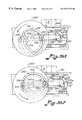
- FIG. 12 is a perspective view of a slug feeder and a slug pick-up station according to the invention for use with a continuous motion case packing apparatus and method in accordance with the invention
- FIG. 13A is a front elevation of an adjustable metering and drive mechanism for varying the number of articles formed into a slug according to a slug feeder of the invention wherein a metering block is illustrated in a first reciprocating position;
- FIG. 13B is a front elevation of an adjustable metering and drive mechanism the metering block is in a second reciprocating position
- FIG. 13C is a front elevation illustrating an adjustable metering and drive mechanism carrier for an adjustable metering device according to the invention wherein the metering block is in a third reciprocating position below the level of support skids on which rows of articles are conveyed;
- FIG. 13D is a schematic view of the cyclic, reciprocating path of the metering block of FIGS. 13A-13C;
- FIGS. 14A-14D are a series of elevational views illustrating the dividing of a continuous flow of articles into slugs of articles in the slug metering section according to the invention wherein the slug contains a prescribed number of articles;
- FIG. 15 is a perspective view illustrating a synchronized drive arrangement for a continuous motion case packing apparatus and method according to the invention for synchronizing the drives of a revolving carriage and article transfer arms/pick-up heads, a slug feeder, and a case indexing conveyor so that article pick-up heads, indexed slugs of articles, and indexed cases are delivered in a synchronized manner at the same delivery rate for case packing;
- FIG. 16 is a sectional view taken along line 16 — 16 of FIG. 12;
- FIG. 17 is a sectional view taken along line 17 — 17 of FIG. 16;
- FIG. 18 is a perspective view illustrating adjustable lanes and bottom support skids for a slug metering section according to the invention in order to adjust the widths and number of lanes in a slug feeder;
- FIG. 19 is a view taken along line 19 — 19 of FIG. 4A illustrating a continuous motion case packing apparatus and method according to the invention wherein only a reciprocating grid set, shown in a chute open position, is used on an article transfer arm as a drop packer according to the invention;
- FIG. 20 is a view taken along line 20 — 20 of FIG. 4B illustrating a continuous motion case packing apparatus and method according to the invention wherein only a reciprocating grid set, shown in a chute closed position for article pick-up, is used on an article transfer arm as a drop packer according to the invention;
- FIG. 21 is a perspective view illustrating a flap unfolding station for continuously unfolding the flaps of indexed cases being continuously conveyed on a continuous motion case packing apparatus according to the invention
- FIG. 22 is a sectional view illustrating an adjustable slug metering section according to the invention.
- FIG. 23 is a perspective view of corner grid fingers and orthogonal chute forming members which form four common corners of adjacent grid chutes according to the invention.
- FIG. 24 is a perspective view with parts separated of an adjustable timing cam coupling for an adjustable metering block mechanism according to the invention.
- FIG. 25 is a perspective view illustrating a metering section and revolving pin bar assemblies for segregating articles into a group or slug of articles in accordance with an alternate embodiment of the invention
- FIG. 26A is a perspective view with parts separated showing an individual pin bar assembly of the revolving pin bar mechanism of FIG. 25;
- FIG. 26B is a partial elevation illustrating a pin bar carrier having a pivot about which the pin bar assembly rotates and a pivot for a cam yoke which positions the pin bar in pivotal movements;
- FIG. 27 is an elevation of a metering section according to the invention with paired pins of the pin bar assembly engaging articles in a last row in a group of articles to segregate the articles from oncoming articles;
- FIG. 28A is a side elevation illustrating a linear path and a radial cam path for a cam of a pivoting pin bar assembly according to the present invention
- FIG. 28B is an enlarged elevation of a pin bar assembly according to the invention entering the radial cam path at the entrance of a metering section according to the invention
- FIG. 28C is a partial end view of a radial cam path at the entrance of a metering section wherein a cam yoke which positions the pin bar is engaging a curved cam surface;
- FIG. 28D is an enlarged elevation of an entrance of a metering section wherein a pin bar for segregating the articles has moved into an operational position
- FIG. 28E is an end view at the entrance of a metering section wherein a cam yoke of a pin bar assembly has engaged a second cam surface to pivot the pin bar forward so they may be received in a crevice between articles for segregating the articles into groups or slugs;
- FIG. 28F is an elevation of an entrance of a metering section wherein pins of a pin bar assembly have been moved into crevices between articles to segregate articles by means of a cam yoke which is shown riding on linear cam bars;
- FIG. 28G is a schematic view illustrating a revolving pin bar mechanism of a metering section which includes a plurality of individual pin bar assemblies and the linear and radial cam paths for the pin bar assemblies;
- FIG. 29 is a prospective view of a metering section according to the invention wherein an alternate embodiment of a metering member is shown having upstanding posts;
- FIG. 30A is an elevation of a timing cam wheel for timing and imparting positional movements of a metering member in a metering section according to the invention with the metering member in an engaging position with respect to a front row of articles in a metered group of articles;
- FIG. 30B is an elevation of the metering section with the timing cam in a position wherein the metering member has reached its left most position
- FIG. 30C is an elevation of a metering section of the invention wherein the timing cam has moved so that the metering member has pivoted out of the path of conveyance of the articles;
- FIG. 30D is an elevation of a metering section wherein the timing cam has moved to return the metering member to the right to begin a new metering cycle;
- FIG. 30E is an elevation illustrating the metering section wherein the timing cam wheel has moved to position the metering member further to the right in readiness for the upward movement of the metering member;
- FIG. 30F is an elevation illustrating the metering section with the timing wheel moved so that the metering member has traveled further to the right;
- FIG. 30G is an elevation of the metering section wherein the cam wheel has turned and the metering member has begun to pivot clockwise to engage the articles needed to begin a new metering operation;
- FIG. 31 is an elevation showing actuation of improved gripper tubes according to the invention.
- FIG. 32A is an enlarged elevation illustrating a pick-up head actuator in a non-actuator position
- FIG. 32B is an enlarged elevation illustrating the pick-up head actuator in a actuating position for releasing articles
- FIG. 32C is a partial elevation with parts cut away illustrating a retracting mechanism according to the invention which acts as a solid member to grip an upright article but allows the gripper end of the gripper tube to yield upon engagement with an inverted article;
- FIG. 32D is an illustration of the gripper end of a gripper tube according to the invention with parts cut away prior to gripping an article;
- FIG. 32E is a partial elevation of the gripper end of a gripper tube according to the invention with parts cut away showing the gripper jaws in an actuated, open position prior to pick up;
- FIG. 32F is an elevation with parts cut away illustrating the gripper end of a gripper tube according to the invention with the gripper jaws in a spring-biased closed, grip position;
- FIG. 33 is an elevation of a front row of gripper tubes of a pick-up head according to the invention illustrating the two axial positions of the gripper tubes, a first axial position in which the gripper tubes have a standard length for gripping articles in an upright configuration and a second axial position in which the effective length of the gripper tube is shortened upon engagement with an inverted article;
- FIG. 34A is a prospective view of the button actuator of a gripper tube according to the invention with the pick-up head actuator in an actuating position to open the gripper jaws when the pick-up head is actuated by an unloading cam;
- FIG. 34B is a partial elevation with parts cut away showing the retracting mechanism wherein a spring of the retracting mechanism is compressed
- FIG. 34C is a partial elevation with parts cut away of a gripper according to the invention showing the gripper jaws spread open when the actuator button is depressed as in FIG. 34A prior to gripping;
- FIG. 35 is an elevation of a one piece spring assembly for a retracting mechanism according to the invention.
- FIG. 36A is an elevation with parts removed of an actuator button and an end cap for a spring assembly according to the invention.
- FIG. 36B is an elevation of a wire travel movement limiter
- FIG. 36C is a side elevation of a compression spring for a gripper actuator according to the invention.
- the apparatus includes a slug feeder, designated generally as B which includes a slug feed conveyor 10 and a slug metering section 12 .
- Slug feeder B receives a continuous flow of articles which are conveyed in at least one longitudinal row from a laner section, designated generally as 14 .
- Slug feeder B continuously forms slugs containing a predetermined number of articles, as metered by slug metering sections 12 , and continuously feeds the slugs to a slug pick-up station, designated generally as 16 .
- the slugs of articles are picked up at the pick-up station and transferred to a case packing station, designated generally as 18 .
- a revolving carriage, designated generally as C carries a plurality of article transfer arms 20 .
- a plurality of article pick-up heads in the form of stacked grid heads and gripper heads, designated generally as 22 , 24 , respectively, are slidably carried on the transfer arms and reciprocate in a linear motion for picking up the slug of articles at pick-up station 16 .
- revolving carriage C carries transfer arms 20 and the article pick-up heads in a curved path which includes a linear transfer section 26 which includes the illustrated horizontal distance between pick-up station 16 and case packing station 18 over which the pick-up heads are lowered vertically to gently deposit the articles into a case.
- a case indexing conveyor designated generally as D, is disposed below the slug feeder and revolving transfer arms to provide a continuous flow of indexed cases 28 to the case packing station 18 where the articles are gently deposited into the case.
- an interval “L” is provided which spaces the continuous, successive slugs 15 , transfer arms 20 and indexed cases 28 so that the case packing process occurs in a synchronized and continuous manner. It is also pointed out, and will be explained fully later, that the rate of delivery, or horizontal speed, of the slugs, transfer arms, and indexed cases is the same.
- the center-line in the direction of conveyance for article pick-up heads 22 , 24 , slugs 15 , and indexed cases 28 lie in a common vertical plane within linear transfer section 26 .
- the horizontal speed of transfer arms 20 and article pick-up heads over the linear transfer section is constant. This enables the pick-up heads and cases to track one another accurately for article transfer and case packing. This also provides reliable insertion of the pick-up heads and release of the articles into the case since only a vertical motion is necessary due to the pick-up heads and cases being parallel and vertically aligned for a linear distance within the linear transfer section.
- the size of slug 15 is determined by the number of longitudinal rows 30 (FIG. 3B) and the number of articles in the longitudinal row. In the example illustrated in the drawings, a slug the size of twelve articles is illustrated. This includes four longitudinal rows 30 containing three articles in a row. As determined by the slug metering section 12 (FIG. 3 A). The size of the interval “L” in the illustrated embodiment may be 30 inches, for example. This provides sufficient space between successive slugs and indexed cases such that most standard slug and case sizes used in case packers may be accommodated. In particular, large cases with flaps folded to a horizontal position can be accommodated.
- each transfer arm 20 includes a steel beam 32 having chain connectors connected to the top and bottom of the beam designated generally as 34 , 36 .
- Top chain connector 34 includes a plate 34 a affixed to beam 32 by any suitable means such as welding, and four legs 34 b extending up from plate 34 .
- Each leg 34 b includes a roller 34 c.
- Also affixed to plate 34 a is a block 36 having a pair of link plates 36 a, 36 b attached to a carriage chain 38 as the two inside links.
- carriage C includes a front carriage plate 40 and a rear carriage plate 42 , spaced apart from each other.
- rollers 34 c of transfer arm connector 34 ride on tracks 40 a and 42 a of the respective carriage plates.
- carriage chain 38 moves the transfer arms along a curved path which will be described in conjunction with FIG. 21 .
- side rollers 34 d carried by plate 34 a roll against the interior sides of carriage plates 40 , 42 .
- Lower transfer arm connector 36 includes a plate 36 a having a pair of bottom rollers 36 b (FIG. 5 ).
- a pair of horizontal connector plates 36 c are affixed to plate 36 and are engaged by a bar 46 affixed to a lower transfer arm drive chain 48 .
- Upper and lower chains 38 , 48 are driven in the same direction and hold the opposing connector ends of transfer arms 20 in a fixed, vertical position as the chains run parallel and horizontal across the transfer section of the carriage (FIG. 15 ). In this position, transfer arms 20 will be connected between a lower run 38 a of carriage chain 38 and an upper run 48 a of bottom drive chain 48 . Both ends of the transfer arm are thus positively conveyed during the pick-up, transfer, and depositing operations. This provides stability and reliability to these operations as the article pick-up heads reciprocate on the transfer arms.
- Carriage plates 40 , 42 may be supported on any suitable frame which includes a pair of vertical standards 50 a, 50 b affixed to the carriage plates and bolted to a base or floor surface.
- pick-up head 22 includes a grid head and pick-up head 24 includes a gripper head. While in the preferred embodiment, both heads 22 , 24 are slidably carried on the transfer arms, it is to be understood that the heads may also be used alone in certain applications.
- grid head 22 includes a plurality of grid closing elements in the form of grid fingers 52 which form an array of grid chutes in a matrix corresponding to the three-by-four matrix of articles 13 in slug 15 .
- the grid chutes, formed by four of the grid fingers, are designated generally as 54 . It is preferred that there is a corner grid finger in each corner of the chute so that the finger surfaces 52 c define a generally rectangular chute (FIG. 23 ).
- grid head 22 may be a suitable grid head such as that shown in U.S. Pat. No. 4,215,521, incorporated here by reference, with the below described modifications.
- grid fingers mounted on the sides of the chutes with suitable actuators may be used instead of the corner mounted fingers as illustrated.
- articles are lowered into such grid sets or heads from the tops of the grid fingers.
- the grid head is designed so that grid chutes 54 are open, and held open in a positive manner, so that the open grid chutes may be received over the articles, i.e. the articles enter the grid head from the bottom of the grid.
- a locking head, designated generally as 56 is provided which includes a plurality of spaced support bars 56 a having locking elements 58 carried on the bars (FIG. 10 ).
- Locking grid 56 includes a rectangular frame 60 by which support bars 56 a are carried.
- Frame 60 is affixed to grid head 24 by means of adjustable brackets 62 .
- a compression spring 64 is affixed between frame 60 and a frame 66 of grid head 64 . This causes a downward force on frame 60 as shown by arrow 65 . This urges an apex portion 58 a of locking elements 58 into a recess formed by the four upper ends 52 d of a set of fingers 52 which form adjacent corners of adjacent chutes. This urges each finger inwardly into the corner of the adjacent chutes whereby the four fingers defining each chute are held in a chute open position for fitting over the individual articles in the slug for pick-up (FIG. 23 ).
- a caming arm 70 which opens and closes the fingers, which have perpendicular backsides 52 a, 52 b.
- Caming arms 70 engage a first backside of the fingers and include a cam 71 having converging surfaces 71 a and 71 b, which intersect at ninety degrees, to wedge behind a second, intersecting backside of the fingers as described in detail in the above referenced grid set patent.
- the caming arm When the caming arm is vertical, the fingers are closed and the chute is open.
- the caming arm is rotated ninety degrees or more (past center), the fingers open from their corner positions into and towards a center line 54 a of chutes 54 to close the chutes.
- Grid fingers 52 pivot about a pivot defined by a retainer ring 72 which also affixes four of the fingers 52 to lateral spacer bars 74 which are spaced across the grid head (FIG. 23 ), all of which may be more fully seen in the above referenced patent.
- Each chute corner is formed by two perpendicular, chute forming surfaces so that the corner fingers are maintained truly vertical and correctly positioned for fitting over articles, as can best be seen in FIG. 10 A.
- camming bar 70 forms one surface for each finger.
- bracing rings 73 surrounding and perpendicular to the caming bars 70 , which form the second surface against which each finger is biased by locking elements 58 in the open chute position.
- a lower chute end 68 is provided which is open for receiving articles and which is closed for retaining articles.
- a grid head actuator is provided for opening and closing the grid elements or fingers 52 , which includes caming arms 70 and cams 71 , and a linkage bar 76 connected to the caming arms.
- Linkage bar 76 is connected to an actuator rod 76 a which in turn is connected to an actuator post 76 b by a slidable connector 76 c.
- Actuator post 76 b is rotatably jornaled in connector plate 36 a at a lower end and to connector plate 34 a at an upper end so that it may swivel and actuate caming arms 70 to open and close grid chutes 54 .
- Forked arm 78 includes a first arm 78 a and a second arm 78 b.
- Both abutments may be adjusted to ensure the correct timing of the actuator in closing and opening of the grid chutes.
- a backup abutment may be provided for each (FIG. 2C) for redundancy to assure operation.
- the first abutment 80 is shown adjustably mounted to rear carriage plate 42 and second abutment 82 is shown adjustably affixed to front carriage plate 40 . The operation of the grid head and actuator will be described more fully hereinafter.
- bearing block 86 includes a cam roller 86 a which rides on a first cam track 88 .
- Rack arm 84 a is affixed to an opposite side of bearing block 86 .
- grid head 22 slides and reciprocates linearly on transfer arm 20 in response to the shape of cam track 88 .
- bearing block 86 includes four corner bearings 86 a affixed within the corners of a hollow interior 86 b of bearing blocks 86 .
- Transfer arm beam 32 slidably engages the bearings for relative sliding movement there between.
- gripper head 24 it too is slidably carried on transfer arm beams 32 .
- FIG. 4B there is a second bearing block 90 disposed above bearing block 86 which slidably receives beam 32 in a similar construction described above with reference to bearing block 86 .
- a rubber pad 92 is carried by a top perimeter of lower bearing block 86 to cushion the nesting of bearing block 90 on top of bearing block 86 . So that the heads may be nested or stacked upon one another along their return path, and at various other stages of operation, rack arms 84 a, 84 b are offset wide on bearing block 86 to accommodate bearing block 90 nesting within the arms.
- a horizontal arm 90 a which is wider than bearing block 90 extends across the front of the bearing block and carries a pair of vertical bars 90 b which support a back frame 94 which supports rack arms 94 a, 94 b.
- Gripper head 24 sits in rack 94 in direct alignment with grid head 22 , as can best be seen in FIGS. 4A-4C. The weights of the gripper head and grid head maintain them in their respective racks.
- Bearing block 90 includes a cam roller 90 c which rides on a second cam track 96 .
- Cam tracks 88 and 96 include plastic bushings affixed to the main frame of carriage C by means of aluminum contoured strips having the desired contour of the cam track. The plastic bushings extend part the aluminum retaining strip to engage the cam rollers of the bearing blocks.
- gripper head 24 includes a frame 98 which holds an array of gripper tubes 99 affixed thereto in a manner that can best be seen in FIG. 11 .
- gripper tubes 99 include attachment ends 99 a affixed to frame plates 98 a as shown.
- a gripper head actuator includes a reciprocating rod 99 b carried within gripper tubes 99 is affixed to a beveled follower 99 c having a downwardly and outwardly beveled edge 99 d.
- Gripper elements 100 pivoted at 100 a include upper arms 100 b received within gripper tube 99 .
- winged jaws 106 When actuator rod 99 b is forced downwardly, beveled camming surface 99 d forces ends 100 b of the gripper elements inwardly to spread them apart to an open position shown in dotted lines at 102 .
- a spring 104 urges gripper ends 100 b away from each other with a sufficient force to lock opposing gripper jaws 106 about a neck 13 a of article 13 .
- Winged jaws 106 also provide a centering device for centering the articles in grid chutes 54 as will become apparent. It is noted that winged jaws 106 include a pair of downwardly and outwardly diverging wings 106 a (FIG. 4 A).
- a gripper actuator mechanism, designated generally as 108 includes a pivotal arm 108 b which pivots about a pivot 108 c.
- a fixed abutment 66 a is shown attached to the frame 66 of grid head 22 .
- Abutment 66 a is affixed to a post 66 b whose lower portion is attached to frame 66 .
- abutment 66 a urges actuator arm 108 a to the horizontal dotted line position shown.
- FIG. 11A illustrates another embodiment for a gripper element may be had which includes a resilient gripper element 107 constructed from a polymeric material, or synthetic or natural rubber.
- the gripper element includes resilient jaws 107 a and 107 b having interior ledges 107 c which grip underneath the article head and around the neck as shown. It is not necessary to open the jaws to receive the article, and to release the article only requires downward actuation of actuator rod 99 b. While the head 24 is referred to as a “gripper” head and the gripper elements have been illustrated as mechanical and resilient gripper jaws, it is to be understood, of course, that any element which attaches to the articles such as suction, or otherwise, may be used on the ends of tubes 99 .
- FIGS. 11B-11E illustrate another alternate embodiment for a gripper head 24 ′ and grid finger head 22 ′.
- the gripper element includes a profiled body which engages the fingers to move the fingers away from the center of the grid chute to the corners of the chutes, as done previously in the operation of grid head 22 .
- gripper head frame 98 and actuator mechanism designated generally as 108 , are the same as disclosed previously.
- a gripper actuator tube 109 a which moves through a gripper tube 109 b when the actuator tube is engaged and moved downwardly by actuator bar 108 d.
- a roll pin 109 c compresses a spring 109 d which is seated on a seated 109 n machined in the interior of gripper head tube 109 b.
- a gripper finger actuator 109 e is also pushed downward causing a surface 109 m to engage finger abutments 109 l and move a pair of gripper fingers 109 f apart.
- gripper fingers are spread apart so that a bottle can be accessed for gripping, or released.
- spring 109 d is compressed so that when actuator bar 108 d is raised back up, actuator tube 109 a also moves upwardly under the force of the compressed spring against roll pin 109 c.
- gripper finger actuator 109 e is also raised upwardly causing gripper fingers 109 f to close around the neck of the bottle due to engagement of finger abutments 109 J with a tapering surface 109 L formed on gripper actuator 109 e.
- the gripper elements include a profiled body 109 h.
- This profiled body engages the grid fingers 52 of modified grid head 22 ′, as can best be seen in FIGS. 11D and 11E.
- profiled body 109 h engages the fingers on the downward decent of the gripper head through the grid head.
- the profiled bodies 109 h move the fingers into their corner positions to allow gripping of the bottle necks, described in the previous paragraph.
- the articles Upon gripping of the bottle necks, and raising of the gripper head, the articles are pulled through the grid fingers whereupon the grid fingers are allowed to close beneath the bottles under a spring force, as is typically used.
- the spring return grid head shown in U.S. Pat. No. 4,215,521 may be utilized without the need of forked actuator 78 (FIG. 5 ).
- the profiled body of the gripper element has a diameter generally equal to the diameter of the base of the bottle which is being gripped and passed through the grid fingers. To accommodate different bottle diameters, the profiled body of the gripper elements may be replaced likewise.
- the grid fingers, and grid chutes defined thereby are fully opened to the equivalent diameter of the bottles. Accordingly, after the bottles are gripped and pulled upwards through the grid fingers, the profiled bodies hold the grid fingers open until the bottles have passed well up into the fingers. The bottles are held above the pivot point of the grid fingers in the grid head. The same opening of the grid chutes occurs as the gripper tubes descend at the case packing station for slug release. The bottles and then the profiled bodies push the fingers into the corners of the grid chutes and box partitions at the case packing station.
- the need to support the bottles on cantilevered knife blades 133 at pick-up station 16 is eliminated because it is no longer necessary for the grid fingers to descend so far past the bottom of the bottles during slug pick up.
- the ends of the grid fingers do not need to pass between the blades in order to descend past the lower ends of the bottles during pick-up as in FIGS. 4B and 8C.
- the profiled body urges the grid fingers to the corner position wherein the chutes are open.
- the necks or tops of the bottles are gripper elements and pulled through the lower open ends of the open grid chutes as the gripper head ascends, with or without relative vertical movement of the grid head.
- the gripper head pull the articles through the open grid chutes and that lowering of the grid head is minimized. This reduces the amount of vertical movement of the grid and gripper heads during the pick up operation, which can be controlled by modifying the cam tracks 88 and/or 96 .
- a laner assembly 110 counts the articles and directs them to a longitudinal rows 30 in order to keep the rows filled (FIGS. 2 B and 3 B). Any suitable laner assembly may be utilized such as that disclosed in U.S. Pat. No. 4,723,649, incorporated by reference herein.
- a laner includes a pivoting guide chute 110 a which swings back and forth across a conveyor to discharge a predetermined number of articles into parallel lanes in which the longitudinal rows or articles are formed. Articles may be fed to the pivoting chute either in single file, or scrambled.
- the lanes are defined by spaced side rails 112 a - 112 e. In the illustrated embodiment, there are five such side rails to define four lanes since the exemplary slug is three-by-four. However, it is to be understood that any number of lanes may be utilized in conventional packers depending on the application being made. At least one lane is needed such as in the packing of large, round containers of beverages and food.
- the spaced side rails extend through the slug feed conveyor 10 and the slug metering section 12 , as can best be seen in FIG. 3 A.
- the lateral spacing between the side rails may be adjusted so that the number and width of the lanes may be adjusted. This may be done in a conventional manner by suspending the side rails from above on transverse bars spaced above the conveyors wherein removable spacers 113 are fitted over the bars to space the side rails to provide the desired spacing (FIG. 12 ).
- variable speed conveyor 114 is utilized in slug conveyor section 10 . Any conventional conveyor belting may be utilized driven in an endless manner.
- a counter finger 115 may be provided for each lane to count the number of articles in the lane. In the event that an article is not counted, the laner may be directed to direct an additional article to that lane where the article is missing.
- slug conveyor 114 terminates at the slug metering section (FIG. 3A) and feeds articles to the slug metering section over a transition plate 116 (FIG. 2 A).
- the articles then move over a support floor defined by a plurality of adjustable bottom skids 118 which are centered in the lanes.
- the bottom skids are adjustable so that they may be made to correspond to the side rail spacing when adjusted.
- an adjustable skid mechanism includes transverse rods 120 (a drive shaft to be described later) which are provided removable spacer blocks 120 a are fitted between adjacent bottom skids 118 .
- the skids may be spring loaded to force them inwardly against the spacer blocks.
- Slug metering section B includes a revolving flight bar mechanism 122 which provides a revolving abutment in the form of flight bars 122 a for separating the continuous stream of articles into discrete slugs.
- flight bars 122 a are spaced at an interval “L” apart.
- the flight bars revolve upwards to divide the articles, and engage the last article 13 c in a slug for conveying the slug of articles forward through the metering section (FIG. 14 D).
- the flight bars are carried on an endless chain 122 b driven by a drive sprocket 122 c and various other idler sprockets 122 d.
- Drive sprocket 122 c is driven by a shaft 123 which in turn is driven by a drive sprocket 123 a.
- Drive sprocket 123 a is driven by a drive chain 123 b in synchronism with the transfer arms 20 and index case conveyor chain 138 , to be described in conjunction with FIG. 15 .
- slug metering section B further includes an adjustable slug metering mechanism which includes a metering block 124 disposed in centrally in each lane which moves in and out of the conveyance path of the articles in a cyclic manner to meter the number of articles in the slug.
- a metering distance d 1 defined between metering block 124 and flight bar 122 a, determines the number of articles in the row and the size of the slug (FIG. 14 D).
- Drive mechanism 126 includes a cam plate 128 having a pair of drive cam slots 128 a and cam pins 128 b. There is a drive rod 128 c (FIG. 12) carried by cam plate 128 on which metering blocks 124 are carried. The metering blocks include a slot 124 a which receives bottom skids 118 so that the metering blocks reciprocate in and out of the conveyance paths of articles supported on the skids centered in the lane (FIG. 12 ).
- Cam plate 128 is affixed to a drive plate 128 c by means of two bolts 128 d.
- Drive plate 128 c includes a drive slot 128 e which slides on at least one drive pin 128 f.
- timing cam 130 is driven off of the same drive which drives flight bar chain 122 b by means of a drive chain 131 connected to a drive sprocket 131 a, idler sprocket 131 b, and timing cam drive sprocket 130 e affixed to drive shaft 120 which is also affixed to timing cam shaft 130 f.
- Drive sprocket 131 a is driven off of shaft 120 to which driven sprocket 122 d of the revolving flight bar mechanism is attached.
- the drive mechanism just described for metering blocks 124 is mounted on a movable carrier plate 132 which includes a gear rack 132 a which meshes with a gear 132 b that is rotatable by a handle 132 c.
- Carrier plate 132 may be affixed to each side frame 12 a and 12 b of the slug metering section by spaced lock bolts with handles 132 d extending through adjustment slots 132 e. By loosening lock bolts 132 d, the carrier plate may be shifted left and right to vary the distance d 1 between the metering block and the flight bars.
- the size of the slug may be advantageously varied, or the metering section may be adjusted to handle different sized articles regardless of the slug size.
- the changeover of slug size or container size required much time and effort in changing out the drive chain and other parts of the metering section to which divider fingers were fixed.
- the timing cam 130 must also be adjusted in its relative position to timing cam drive shaft 130 f.
- timing cam 130 is mounted on drive shaft 130 f by an adjustable coupling, designated generally as 129 , between the timing cam wheel and the shaft, as can best be seen in FIG. 24 .
- the timing cam wheel may be manually turned so that the relative positions of the timing cam slot 130 a and a follower pin 130 d may be adjusted and the timing of the metering blocks and their cyclic motion is correct for the new distance d 1 .
- follower pin 130 d is affixed to drive plate 128 c and received in camming slot 130 a.
- adjustable coupling 129 includes a female spline 129 a formed in an end of shaft 130 f, and a male spline 129 b formed on the end of a stub shaft affixed to timing cam 130 .
- the timing cam 130 may be rotated relative to shaft 130 f to vary their relative positions. This sets the timing cam in the correct position for the new metering distance d 1 and slug size. This can be done by visually setting the cam wheel at the same position relative to pin 130 d or using indexing indicia when provided as illustrated.
- the threaded rod is then backed off bringing the male and female splines back into driving engagement with each other.
- the metering block is reciprocated under the drive of the timing cam which is driven in synchronism with the flight bar chain and entire packer.
- the cam plates include a straight cam slot and a vertically inclined cam slot.
- the meter block moves longitudinally when the cam pins are in the straight portion of the cam slots. This moves the metering block longitudinally.
- the metered block slides up and down.
- the timing cam controls the timing of the meter block movement.
- FIGS. 13A-13C The cyclic movement of metering block 124 will now be described by referring to FIGS. 13A-13C.
- the metering block is to the right and up, extending above the surface of the bottom skids to abut a front a first article 13 a in the row of articles contained in the slug.
- metering block 124 is moved to the left and up.
- the metering block is to the left and down, i.e it has dropped below the bottom skid 118 .
- the articles are conveyed past the metering block forward to the slug pick-up station 16 (FIG. 12 ).
- An article counter mechanism 133 g may be utilized to shut down the packer in the event that certain conditions exist in the counting of articles. For example, if three articles are not counted in the correct position in the slug, that is an indication that a bottle may be lying down in the lane, or missing, which could cause a significant malfunction condition at the slug pick-up station, requiring packer shut down to be described in conjunction with FIG. 15 .
- FIGS. 14A-14D the operation of the slug metering section will now be described.
- articles 13 are conveyed by the slug feed conveyor onto the bottom skids 118 of the slug metering section. Regardless of the number of lanes or rows, in each row, the first article in the slug is 13 a, the second articles is 13 b, and the last article is 13 c. The first article in the next slug will be 13 d.
- the articles continue to be fed at a desired speed by variable speed slug conveyor 114 onto the support skids.
- the metering block is up and the flight bar begins to revolve up to divide the articles.
- metering block 124 is up and first article 13 a engages metering block 124 .
- flight bar 122 a rises underneath article 13 d to divide the continuous flow of articles. It will be pointed out that as long as metering block 124 is up, articles 13 will be conveyed at a sufficiently fast speed by conveyor 114 to maintain the articles in contact, as shown.
- metering block 124 begins to drop, as can best be seen in FIG.
- slug feed conveyor 114 will momentarily slow down so that the slug 15 is quickly conveyed away by the revolving flight bar, leaving article 13 d behind, and forming a separated slug of articles, with a gap between the next slug. It is important to note that a fast conveyor speed of conveyor 114 will keep articles 13 snugly against each other as long as metering block 124 is up. This enables flight bar 122 a, which is above the bottom surface of the articles to lift up first article 13 d in the second slug being formed and tilt it rearwardly to divide the articles into slugs.
- the relative speeds of the revolving flight bar, metering block, and slug conveyor may be controlled using any suitable arrangement, such as that shown in conjunction with FIG. 15 .
- Transition plate 116 facilitates transfer from the slug feed conveyor to the bottom skids.
- a case indexing station/conveyor D is disposed vertically below laner 14 and slug feeder B, and the conveyor continues through case packing station 18 .
- Empty cases, with or without partitions are fed into and indexed at the station.
- the indexing conveyor includes a driven belt conveyor 136 having two spaced belt runs 136 a, 136 b with a center drive chain 138 which is separate and independent.
- Drive chain 138 carries a plurality of case engaging dogs 138 a for conveying indexed cases to the case packing station.
- the indexed cases may be with or without flaps. If the indexed cases have flaps, a suitable flap opening station may be provided.
- a flap opening station designated generally as F, may be provided as shown in FIG. 21 .
- Flap opening station F may include a pair of suction heads 140 a, 140 b which pivot from a vertical to a horizontal position under the control of a suitable reciprocating drive arrangement shown to include a cam 141 which rocks 180 degrees and drives the suction head through a chain 141 a. In the horizontal position, suction is applied and major flaps 142 a, 142 b of a case 142 are opened to a vertical position.
- the case with major flaps held vertical is conveyed underneath a horizontal plow 144 having diverging wings and diverging sides.
- the diverging plow sides fold the vertical flaps over from the vertical position to a horizontal position.
- the horizontal flaps are engaged by guide wires 146 on both sides of the plow which hold the major flaps horizontal.
- the case is conveyed underneath a suspended pivot finger 148 with a hook end 148 a which engages a rear flap 142 c, and folds it open to a horizontal position.
- a rocker arm 150 having a freely pivoting pivot finger 150 a reciprocates and engages a front minor flap 142 d and opens it horizontal.
- Pivot finger 150 a pivots freely in a counter-clockwise direction so that on the return stroke of the rock arm, the pivot finger returns to a home position in which it is generally vertical.
- a reciprocating, horizontal wiper arm 152 pivots forward to wipe over the rear and front minor flaps to ensure they are horizontal before they enter a center angle arm 154 which holds the flaps horizontal.
- a middle guide wire 154 a continues to hold the flaps horizontal as indexed cases move continuously through the conveying process. Outside guide wires 146 and center wire 154 a hold the flaps open for case is packing through the case packing station.
- a suitable drive and control arrangement may be provided for the above described flap opening elements as, for example, disclosed in U.S. Pat. No. 4,587,792.
- a synchronized drive arrangement is provided for driving carriage C, slug feeder B, and case indexing conveyor D in synchronization and at the same speed so that the article pick-up heads, slugs, and cases are conveyed in intervals “L” for accurate timing of slug pick up and deposit.
- There is an electric drive motor 160 which drives a system drive shaft 162 through a pulley 162 a and clutch 164 , which may be any suitable electromagnetic clutch for starting and stopping the case packer operation.
- Clutch 164 may be actuated and deactuated manually, and in response to a controller 165 .
- Upper gear box 166 drives top carriage chain 38
- lower gear box 168 drives the lower carriage chain 48 through a drive sprocket 48 a, and drives indexing conveyor chain 138 through a common drive shaft 170 and drive sprocket 172 .
- Revolving flight bar mechanism 122 is driven through drive sprockets 123 a and 122 c, which are driven off of drive chain 123 and shaft 123 (FIG. 12 ).
- Drive chain 123 is driven off of a indexing conveyor chain and shaft 138 , 170 a in unison therewith, through a drive sprocket 138 b.
- the drive for metering block mechanism 126 has been explained previously in conjunction with the slug feeder.
- Variable speed slug feed conveyor 114 is driven by a variable speed motor and controller 114 a as described in the operation section below.
- a conventional safety clutch 172 is provided through which the slug feed conveyor and revolving flight bar are driven.
- a programmable limit switch (PLS) 174 may be provided for use with one example of a controller for the apparatus, and is driven off of shaft 170 a and clutch 172 .
- PLS 172 provides sequencing of several events over the cycle interval “L” in order that several control functions may be had as described above.
- the PLS is divided into 300 increments so that the interval “L” is divided into increments of 0.1 inches for the example where “L” is thirty inches. At prescribed increments, or ranges of increments, certain control functions may be looked at.
- signals from photo cells may be processed by controller 165 over a desired increment range to assure that the case will be in a correct position a the case packing station.
- Photo cells may also be positioned over the cases to look into the cells and detect whether all cells are empty, a flap is closed, or a case is missing.
- the PLS is used to vary the speed of slug feed conveyor 114 . That is, over a desired increment range, the conveyor is speeded up to keep articles in tight contact in the slug metering section while the metering block is up during slug formation, as described above.
- Controller may be any programmable controller or computer, the provision of a which would be well within the purview of a skilled artisan in the control art, having been taught the principles of the invention.
- first cam track 88 and bearing block 86 ; and second cam track 96 and bearing block 90 provide a vertical motion mechanism by which grid head 22 and gripper head 24 , respectively, are caused to slide over transfer arms 20 in reciprocating linear movements to be described in reference to FIGS. 2C-2G. These movements will first be described by referring to FIG. 2C, and locations 1 through 9 on the cam tracks and across the linear path of transfer arm 20 as it is carried by carriage C.
- grid head 22 and gripper head 24 are positioned directly above and in alignment with a slug 15 , as can best be seen in FIG. 2 D. Both the grid chutes and the gripper jaws are open. The gripper jaws are open because gripper actuator arm 108 a is still engaged by abutment 66 a, as can best be seen in FIG. 4 A. However, as soon as grid head 22 begins its descent over cam track portion 88 a, abutment 66 a moves downwardly to release gripper actuator arm 108 a causing the gripper jaws to close around the necks of articles 13 . From locations 2 - 4 , the grid set descends to its lower most position at slug pick-up station 16 (FIG. 2 E).
- the gripper jaws grip the articles.
- the articles 13 have entered the open ends of the grid chutes 54 and the grid fingers defining the chutes have descended a sufficient distance past the bottoms of cantilevered blades 133 to enclose articles 13 .
- grid actuator arm 78 a engages abutment 80 moving all of the grid fingers toward the center of the chutes to close off the chutes and positively retain the articles in the chutes (FIG. 4 B).
- both the grid head and the gripper head begin their descent to case packing station 18 over cam track portions 88 c and 96 b, respectively.
- grid set 22 and gripper head 24 are at the case packing position.
- the closed grid fingers of grid head 22 have penetrated into the case at their lowest point (FIG. 4 C).
- the closed grid fingers easily enter the individual cells of the partitioned case due to their converging configuration.
- the gripper tubes, grid chutes, slugs, and cells defined by the partitions in the cases are arranged in a corresponding matrix.
- second actuator arm 78 b strikes second abutment 82 to open the grid chutes. This causes the grid fingers to move away from the center of the chute into the corners of the case cells, or against the chute forming surfaces 70 , 73 against which the corner fingers are urged in the chute open position (FIG. 10A) when cases without partitions are being packed. For purposes of clarity, the partitions have been omitted from FIG. 4 C. As the gripper head reaches its lowest point of descent somewhere near the end of cam track portion 96 b, gripper actuator arm 108 a is again engaged by abutment 66 a causing the gripper jaws to open.
- bearing block 90 which carries gripper head 24 rests on top of bearing block 86 which carries grid head 24 .
- the nested heads are now in a position to be lifted out of the case for their return trip back to slug pick-up station 16 . This occurs between locations 8 and 9 over cam track portion 88 e, FIG. 2H, whereupon grid head 22 travels upwardly to begin its return trip.
- carriage C moves the transfer arm and pick-up heads in a closed, vertical plane curve 160 which includes a linear path 160 , which also includes linear transfer section 126 , and a curvilinear return path 162 .
- the curvilinear return path may also be considered as including a portion of path 160 in excess of the linear transfer section.
- Slug metering section 12 ′ includes a revolving pin bar mechanism 198 which provides a revolving article separator for separating the continuous stream of articles into discrete slugs. (FIG. 28 G).
- the revolving pin bar mechanism includes a plurality of pin bar assemblies, designated generally as 206 , spaced at an interval “L” apart (FIGS. 25 and 28 G).
- Each pin bar assembly 206 includes a flight bar 200 having a pin bar carrier 208 rotatably carried thereon. Flight bars 200 are carried on an endless chain 204 driven by a drive sprocket 123 a, 123 c and various other idler sprockets as described in the previous embodiment (FIGS. 12 and 15 ). Other means for pivotally mounting the pin bar assemblies to a continuously revolving mechanism may also be utilized.
- Pin bar assembly 206 includes pin bar 210 carried by pin bar carrier 208 .
- Pin bar carrier 208 includes an elongated carrier bar 208 a and a plurality of carrier arms 208 b between which are carried a plurality of skid plate support rollers 212 which rotate on flight bars 200 .
- Skid plate support rollers 212 roll underneath and support skid plates 196 which extend longitudinally in each lane and support the articles (FIG. 25 ).
- Pin bar 210 includes pairs of pins 214 wherein each pair includes spaced pins 214 a and 214 b. The spacing between 214 a and 214 b is determined by the diameter of the bottle or width of the package being processed.
- Pin bar 210 is preferably a one-piece manufacture. Different pin bars may be manufactured having different pin spacings to accommodate different article dimensions. The pin bars may be interchanged easily by means of a detachable mount in the form of a keyhole connector 218 which includes a keyhole 218 a (first attachment element) formed in pin bar 210 and a key bolt 218 b (second attachment element) carried by carrier bar 208 a (FIG. 26 A). Means for locking the pin bar in place including a ball indent arrangement 209 .
- cam yoke 220 fixed to a shaft 222 which in return is fixed to the end carrier arm 208 b of pin bar carrier 208 .
- pin bar carrier 208 pivots about flight bar 200 in operation at a pivot 224 .
- Shaft 222 of cam yoke 220 is offset forward and upward with respect to flight bar pivot 224 in the direction of travel 223 , as can best be seen in the dotted line position of FIG. 26 B.
- cam yoke 208 is contained within a cam bar mechanism 226 which includes an upper cam bar 226 a and a lower cam bar 226 b during its linear travel underneath skid plates 196 .
- Lower cam bar 226 b prevents the pin bar from falling under the force of gravity and upper cam bar 226 a prevents the pin bar from rotating backwards as it bears against the bottles.
- Cam yoke 220 rests against a bottom cam bar 228 on its return path. In between the linear cam paths defined along cam bars 226 and 228 , cam yoke 220 travels in a radial cam path, designated generally as 230 , as can best be seen in FIG. 28 A.
- Radial cam path 230 is defined by a cam block, designed generally as 232 , and an outer cam plate 234 .
- cam plates 234 There are two cam plates 234 , one at the infeed end as shown at 234 a and the second at the outfeed end which is shown at 234 b (FIG. 28 G).
- Cam block 232 is mounted to an idler shaft 236 carried by the frame.
- a locking bolt 238 tightens cam block 232 on shaft 236 .
- Cam plate 234 includes a cam surface 240 against which cam yoke 220 bears initially as it enters radial cam path 230 . At its upper portion, namely 240 a, cam surface 240 insures that cam yoke 220 engages a cam surface 242 of cam block 232 .
- Cam surface 242 causes pin bar 210 to be rotated by cam yoke 220 so that pins 214 engage the bottles at the proper time and position.
- cam surface 240 assures that cam yoke 220 is urged against cam surface 242 to provide reliable operation. It is important at this phase of operation, that cam yoke 26 pivots pins 214 in the proper position for reliable upright insertion between bottles (FIG. 28 F).
- pins 214 engage between bottles 13 to separate them into slugs along with a metering bar 246 (FIG. 29 ).
- pins 214 are aligned directly with an entrance 244 which defines a crevice between adjacent bottles.
- pins 214 is raised upwardly in the crevice between bottles by cam surface 242 .
- Cam surface 242 a imparts a slight forward rock to the pin bar and pins 214 .
- pin carrier assembly 206 is moving at a higher speed than conveyor 114 which is bringing bottles 13 into the metering section so that the bottles between pins 214 and a metering bar assembly 245 are separated and conveyed away as a slug.
- metering bar assembly As can best be seen in FIGS. 29 and 30 A- 30 G, metering bar assembly, designated generally as 245 , operates in synchronization with pin carrier assembly 206 much like metering block 124 and flight bar 122 a of the embodiment of FIGS. 13A-13D and 14 A- 14 D.
- Metering bar assembly 245 is disposed across each lane and includes a metering bar 246 a having spaced pairs of posts 246 which move (pivot) in and out of the conveyance path of the articles in a cyclic manner to meter the number of articles in the slug along with pin bar assembly 206 .
- Metering bar 246 a is driven by a drive mechanism in cyclic movements in and out of the conveyance path independent of the revolving pin bar assembly 206 in any suitable manner such as by a drive mechanism disclosed in the embodiment of FIGS. 13 and 14. Since such a drive mechanism has already been described in detail, only so much of the drive mechanism as is necessary to understand the alternate embodiment will be referred to.
- the metering bar is reciprocated in synchronism with the drive of flight bar chain 204 , and entire packer.
- the drive mechanism for metering bar 246 a is mounted on a movable carrier plate 132 ′ like the embodiment in FIG. 13 .
- the carrier plate may be shifted left and right using gear handle 132 c ′ to vary the distance between metering bar and the pin bar assembly.
- the size of the slug may be advantageously varied, or the metering section may be adjusted to handle different sized articles regardless of the slug size.
- timing cam plate 260 is carried on cam plate carrier 132 ′ and includes an outer cam slot 252 and an inner cam slot 254 (FIG. 30 A).
- An actuator linkage includes a link 256 having a longitudinal slot 258 which slides about a pivot 258 a which secures actuator 256 to the adjustable cam carrier.
- Affixed to actuator link 256 is a cam follower or pin 270 which rides in cam slot 252 .
- There is a second cam follower or pin 272 which rides in second cam slot 254 .
- Cam pin 272 is affixed to a reciprocating linkage in the form of a bar 274 which reciprocates in linear movement.
- Reciprocating bar 274 slides between guide blocks 275 a, 275 b, which are affixed to carrier 132 ′, as the bar reciprocates.
- actuator link 256 At the end of actuator link 256 is carried a rod eye 276 having a pivot 276 a secured to a crank arm 278 that is affixed to metering bar 246 .
- Crank arm 278 is affixed to a bar 246 a by means of a bolt 280 .
- a vertical standard 284 is affixed by means of bolts 286 to reciprocating bar 274 .
- Standard 284 provides a pivot support for crank arm 278 and metering bar 246 . The entire assembly thus described moves with timing cam carrier 132 ′, as described above, to adjust the distance “L”.
- metering bar 246 reciprocates in linear movement between guide blocks 275 a and 275 b under control of cam pin 272 as it rides in cam slot 254 .
- actuator link 256 undergoes angular and linear motion as cam pin 270 rides in cam slot 252 .
- cam slot 252 is formed on the front of timing cam 260 while cam slot 254 is formed in the back side of the timing cam.
- metering posts 246 are in a first, up position in which they engage the front articles in a slug of articles.
- reciprocating bar 274 has moved to it forward most left position and at that time, metering bar (posts) 246 is pivoted to a second, down position in FIG. 30 C.
- FIG. 30C the reciprocating bar has reached its left limit position and the reciprocating bar begins to travel to the right as shown in FIG. 30 D.
- metering posts 246 are still in the down position.
- the slug of articles is conveyed to the left in FIG. 30E while the metering bar, in down position, continues to travel to the right so that posts 246 engage the front articles of another slug of articles.
- FIG. 30E The slug of articles is conveyed to the left in FIG. 30E while the metering bar, in down position, continues to travel to the right so that posts 246 engage the front articles of another slug of articles.
- reciprocating bar 274 reaches its right most position and the metering bar is about to the pivoted to the first, up position, as shown in FIG. 38, as a reciprocating bar against its travel to the left.
- the metering bar has moved in synchronization with the pin bar assembly 260 so that the pin bar parts engage the front of a slug of articles as the pins 214 of the pin bar begin to insert behind the back row of the articles in a slug for separation of the slug from the stream of articles upstream.
- the operation and synchronization of the metering bar and pin bar assembly are to be carried out in the same manner as the metering block and flight bars described in the first embodiment of the invention.
- the continuous motion apparatus of the present invention can be used for unpacking bottles or other articles from cases as well as packing bottles and articles into cases.
- the machine When used as an unpacking or depacking continuous motion apparatus the machine is reversed in its operation. When the apparatus is run in the reverse direction, minor adjustments need to be made to the apparatus as will be well within the purview of one skilled in the art having been taught the advantageous and features of the present invention.
- revolving carriage C and transfer arms 20 revolve in a counterclockwise direction.
- Article pick-up heads 2 , 24 are lowered into a case having empty bottles, grip the necks of the bottles, lift the bottles out of the case, and place the empty bottles on a conveyor at a station 16 which is a deposit station rather than a pick-up station.
- an index conveyor such as illustrated in FIG. 2A, will be used to convey the cases and empty bottles beneath the pick-up heads in synchronization.
- the empty bottles will be deposited and released upon a conventional outfeed conveyor at the release station.
- the empty bottlers will be conveyed away for further processing in a conventional manner.
- cam tracks 88 , 96 will be replaced with modified cam tracks to provide proper positioning and timing of the pick-up heads for depacking, as is well within the purview of the average artisan.
- the entire apparatus is operated in a reverse direction with minor adjustments.
- the means for presenting the articles in the form of a slug or group of articles at the pick-up station will be the case-contained group of empty bottles or articles.
- FIGS. 32A through 36C another embodiment of an article gripper or gripper tube 300 is illustrated which has particular utility when the machine is operated in a depacking mode, but may also be used for packing.
- gripper head 24 includes frame 98 which holds an array of gripper elements or tubes 300 affixed thereto in a manner that can best be seen in FIG. 33 .
- gripper tubes 300 include attachment ends 300 a affixed to frame plates 98 a as shown.
- a gripper tube actuator includes a reciprocating mechanism, designated generally as 300 b, carried within gripper tubes 300 .
- the reciprocating mechanism is comprised of a non-compressible rod 99 b or 109 a in the previously disclosed embodiments of FIGS. 11-11E
- reciprocating mechanism 300 b is illustrated now as a compressed spring mechanism which acts as a solid, non-compressible member until a sufficient load is placed on it.
- Article gripper 300 includes a tube slip collar 302 which is slidably received over an inner tube 304 .
- reciprocating mechanism 300 b includes a spring 306 having a first end which abuts a flange 308 a of an actuator button 308 .
- Actuator button 308 is actuated by an actuator bar 108 a of FIGS. 11-11E.
- actuator bar 108 a be actuated by a loading cam for gripping and an unloading cam for releasing in the form of abutments such as 80 and 82 properly place along the cam track of the pick up head.
- actuator bar 108 a In operation, when actuator bar 108 a is activated, actuator button 308 is depressed causing spring 306 to exert downwardly on jaw actuator 310 . In return, spring 312 pushes down on jaw hooks 314 a, 314 b causing jaws 314 , 316 to open (FIG. 32 E). After profiled body 318 is received over neck 317 of the bottle, actuator bar 108 a is retracted causing jaws 314 , 316 to close under the spring release force of 312 , and the engagement of upper ends 314 b, 316 b of the jaws with a locking taper 320 which holds the jaws closed around the neck of the bottle (FIG. 32 F).
- the continuous motion apparatus will operate in the depacking mode without any problem.
- the gripper head of the present embodiment will operate as follows.
- the gripper head 24 ′ and article tubes 300 will operate as follows.
- the left most article gripper 300 has assumed the following position. Profile body 318 has encountered and struck the bottom of inverted bottle 317 a. This has caused spring 306 to be sufficiently loaded to compress and inner tube 304 slides within slip collar 302 .
- the end of inner tube 304 has abutted the end of slip collar 302 , as seen in FIG. 33 .
- compression of spring 306 has taken place.
- the spring rate of spring 306 is greater than the spring rate of spring 312 ; about 7 pounds per inch and about 4.8 pounds per inch, respectively. This allows spring 312 to normally compress without any compression of spring 306 for gripper jaw actuation in normal operation. However when an inverted bottle is encountered by an article gripper, spring 306 is compressed allowing the remaining article grippers to operate normally as described above.
- spring 306 may have a spring rate of 7, and spring 312 may have a spring rate of 4.
- the gripper tube compresses to a shortened axial length when encountering an abnormal condition such as when striking an inverted article, an out of position article, or any other miscellaneous obstruction like broken glass.
- FIGS. 35-36C show an alternate arrangement for a reciprocating mechanism 330 of a gripper head actuator which is particularly advantageous as a one-piece construction which is pre-compressed and ready for installation.
- Reciprocating mechanism 330 may be used in lieu of reciprocating mechanism 300 b.
- the mechanism is completely self-contained and preloaded, whereas in the embodiment of mechanism 300 b, washers or spacers may be needed between flange 308 a and the end of spring 306 to preload the spring at a desired compression (FIG. 34 A).
- the unitary construction of mechanism 330 includes an integral actuator button 332 having a thin insert rod 332 a.
- An actuator button on cap 332 b is embedded or carried on the opposing end of the mechanism.
- FIG. 36 B There are a pair of spring loops 334 and 336 having their bends interlooped (FIG. 36 B). Opposing ends of the loop springs include hooks at 334 a and 336 a, respectively.
- a compression spring 340 is received over the looped spring construction. Hooks 334 a are fixed in actuator button 332 , and hooks 336 a are affixed to end cap 332 b.
- the reciprocating mechanism is one piece and preloaded. Again reciprocating mechanism 330 acts as a solid member until an upside down bottle is encountered whereupon loop springs 334 , 336 are allowed to move relative to each other allowing spring 340 to press. In this manner the remaining article grippers are allowed to descend and grip the right bottles.
- a advantageous construction can be had for a continuous case packing and depacking apparatus can be had according to the invention wherein, in a packing mode, articles may be positively held by article pick-up heads for reliable transfer from a pick-up position over a linear section in which no horizontal acceleration occurs, and a vertical descent for case packing is smooth and gentle.
- the apparatus may be operated in a depacking mode wherein the problem of inverted bottles is overcome in a reliable manner.
- a slug feeder B and adjustable metering mechanism are provided which facilitate a quick and easy changeover to the packaging of different sizes of articles and slugs without the time consuming replacing of parts and down time.
Abstract
Description
Claims (33)
Priority Applications (6)
| Application Number | Priority Date | Filing Date | Title |
|---|---|---|---|
| US09/301,394 US6571532B1 (en) | 1994-11-10 | 1999-04-28 | Continuous motion case packing apparatus and method |
| US09/418,619 US6729103B1 (en) | 1994-11-10 | 1999-10-15 | Continuous circular motion case packing and depacking apparatus and method |
| US10/068,601 US6748725B2 (en) | 1994-11-10 | 2002-02-05 | Continuous circular motion case packing and depacking apparatus and method |
| US10/223,398 US20030106288A1 (en) | 1994-11-10 | 2002-08-19 | Continuous circular motion case packing and closure apparatus and method |
| US10/232,550 US6722101B2 (en) | 1994-11-10 | 2002-08-29 | Continuous circular motion case packing and closure apparatus and method |
| US10/637,740 US6883296B2 (en) | 1994-11-10 | 2003-08-08 | Case tab-lock slitting and flap sealer in combination with a continuous radial motion case packing apparatus and method |
Applications Claiming Priority (4)
| Application Number | Priority Date | Filing Date | Title |
|---|---|---|---|
| US08/338,026 US5588282A (en) | 1994-11-10 | 1994-11-10 | Continuous motion case packing apparatus and method |
| US08/736,376 US5797249A (en) | 1994-11-10 | 1996-10-24 | Continuous motion case packing apparatus and method |
| US13732798A | 1998-08-20 | 1998-08-20 | |
| US09/301,394 US6571532B1 (en) | 1994-11-10 | 1999-04-28 | Continuous motion case packing apparatus and method |
Related Parent Applications (1)
| Application Number | Title | Priority Date | Filing Date |
|---|---|---|---|
| US13732798A Continuation-In-Part | 1994-11-10 | 1998-08-20 |
Related Child Applications (2)
| Application Number | Title | Priority Date | Filing Date |
|---|---|---|---|
| US09148619 Continuation-In-Part | 1999-10-15 | ||
| US09/418,619 Continuation-In-Part US6729103B1 (en) | 1994-11-10 | 1999-10-15 | Continuous circular motion case packing and depacking apparatus and method |
Publications (1)
| Publication Number | Publication Date |
|---|---|
| US6571532B1 true US6571532B1 (en) | 2003-06-03 |
Family
ID=27384997
Family Applications (1)
| Application Number | Title | Priority Date | Filing Date |
|---|---|---|---|
| US09/301,394 Expired - Fee Related US6571532B1 (en) | 1994-11-10 | 1999-04-28 | Continuous motion case packing apparatus and method |
Country Status (1)
| Country | Link |
|---|---|
| US (1) | US6571532B1 (en) |
Cited By (25)
| Publication number | Priority date | Publication date | Assignee | Title |
|---|---|---|---|---|
| US20040003574A1 (en) * | 1994-11-10 | 2004-01-08 | Hartness Thomas Patterson | Continuous circular motion case packing and depacking apparatus and method |
| US6722101B2 (en) | 1994-11-10 | 2004-04-20 | Hartness International, Inc. | Continuous circular motion case packing and closure apparatus and method |
| US20040079051A1 (en) * | 2002-10-25 | 2004-04-29 | Lippman Glenn W. | Semi-automatic vial closing apparatus |
| US20040112714A1 (en) * | 2002-02-09 | 2004-06-17 | Emmanuel Davaillon | Article grouping mechanism |
| US20040237469A1 (en) * | 2001-10-29 | 2004-12-02 | Pedro Serras Vila | Machine for the automatic dispensing of protective, separation dividers for groups of bottles which is intended for bottle packaging lines |
| US20050045244A1 (en) * | 2003-08-28 | 2005-03-03 | Hartness Thomas P. | Circular motion filling machine and method |
| US6883296B2 (en) | 1994-11-10 | 2005-04-26 | Hartness International, Inc. | Case tab-lock slitting and flap sealer in combination with a continuous radial motion case packing apparatus and method |
| US6983577B2 (en) | 1999-10-15 | 2006-01-10 | Hartness International, Inc. | Circular motion filling machine for processing parallel rows of containers and method |
| US20060207220A1 (en) * | 2004-09-02 | 2006-09-21 | Graphic Packaging International, Inc. | Packaging system having loading carousel |
| US7392630B2 (en) | 2004-09-02 | 2008-07-01 | Graphic Packaging International, Inc. | Packaging system having loading carousel |
| US20090110525A1 (en) * | 2007-05-23 | 2009-04-30 | Tim Criswell | Automatic Case Loader and Method for Use of Same |
| US20110173930A1 (en) * | 2008-07-04 | 2011-07-21 | Benoit Poutot | Packaging machine and method of packaging articles |
| WO2011153487A1 (en) | 2010-06-04 | 2011-12-08 | Allfast Fastening Systems, Inc. | A metal part coated with a first non - hexavalent chromium chemical conversion coating and a second sol gel coating and a process for its production |
| US20120324840A1 (en) * | 2011-06-27 | 2012-12-27 | Multivac Sepp Haggenmuller Gmbh & Co. Kg | Packaging arrangement with transport device |
| US20150027084A1 (en) * | 2012-03-15 | 2015-01-29 | Nissin Foods Holdings Co., Ltd. | Container filling apparatus |
| CN104443500A (en) * | 2014-11-27 | 2015-03-25 | 佛山市嘉荣智能机械有限公司 | Automatic boxing method and device for bottles |
| US20160016683A1 (en) * | 2014-07-17 | 2016-01-21 | Pacwell Ip Pty Ltd | Carton packing apparatus |
| US9434558B2 (en) | 2013-01-20 | 2016-09-06 | Wynright Corporation | Automated truck unloader for unloading/unpacking product from trailers and containers |
| WO2016196278A1 (en) * | 2015-05-29 | 2016-12-08 | Graphic Packaging International, Inc. | Packaging system |
| US20190084700A1 (en) * | 2017-09-21 | 2019-03-21 | Yamato Corporation | Depositor apparatus |
| WO2020020523A1 (en) * | 2018-07-24 | 2020-01-30 | Krones Aktiengesellschaft | Handling and/or packaging apparatus and method for packaging articles |
| EP3686113A1 (en) * | 2018-12-14 | 2020-07-29 | Krones Aktiengesellschaft | Handling and/or packaging device and method for repacking item groups |
| US11198528B2 (en) * | 2018-02-13 | 2021-12-14 | Krones Aktiengesellschaft | Packaging device and method for fitting an external package with a dividing element |
| WO2022224276A1 (en) * | 2021-04-22 | 2022-10-27 | Abhijit Salpe | Dual lane, premade pouch packaging machine |
| CN115258240A (en) * | 2022-08-05 | 2022-11-01 | 江苏泗阳协力轻工机械有限公司 | Boxing machine |
Citations (38)
| Publication number | Priority date | Publication date | Assignee | Title |
|---|---|---|---|---|
| US1481259A (en) | 1923-01-19 | 1924-01-22 | James E Harrison | Fishing tool |
| US1538406A (en) | 1924-06-19 | 1925-05-19 | Chalmer D Mccarty | Well-fishing tool |
| US1583767A (en) | 1925-10-21 | 1926-05-11 | Merrill I Akins | Fishing tool |
| US2277688A (en) | 1938-07-08 | 1942-03-31 | Edward Ermold Co | Packaging machine |
| US2350692A (en) | 1943-12-28 | 1944-06-06 | Alexander Healy Jr | Fishing tool |
| US2730279A (en) | 1951-11-23 | 1956-01-10 | Graham Enock Mfg Company Ltd | Bottle crating and decrating machines |
| US2760316A (en) | 1952-08-12 | 1956-08-28 | Okulitch George Joseph | Automatic case filling machine |
| US2890553A (en) * | 1953-11-16 | 1959-06-16 | Crown Cork & Seal Co | Case filling machine |
| US2921425A (en) * | 1957-04-04 | 1960-01-19 | Seval Andre Amand Etienne | Very high capacity boxing machine |
| US3012811A (en) | 1960-03-21 | 1961-12-12 | Sandrock Raymond James | Gripping tool |
| US3505787A (en) | 1968-03-04 | 1970-04-14 | Lodge & Shipley Co | Case packer |
| US3553932A (en) | 1969-02-05 | 1971-01-12 | Lodge & Shipley Co | Case packer having floating guides |
| US3553927A (en) | 1968-03-13 | 1971-01-12 | Carlos Anglade Jr | Apparatus and method for packing articles in containers |
| US3555770A (en) | 1969-01-28 | 1971-01-19 | Lodge & Shipley Co | Case packer |
| US3555773A (en) | 1969-06-23 | 1971-01-19 | Lodge & Shipley Co | Four-head carriage for case packer |
| US3648427A (en) | 1970-08-11 | 1972-03-14 | Emhart Corp | Apparatus for loading frangible containers |
| US3727366A (en) | 1970-10-19 | 1973-04-17 | Fmc Corp | Casing machine |
| US3805476A (en) | 1971-02-25 | 1974-04-23 | Mitsubishi Heavy Ind Ltd | Method and apparatus for encasing of articles |
| US3864890A (en) * | 1973-01-08 | 1975-02-11 | Huntingdon Ind Inc | Bottle packaging machine and method |
| US3938847A (en) * | 1972-11-13 | 1976-02-17 | Industrial Automation Corporation | Gripper means |
| US3944058A (en) * | 1973-04-19 | 1976-03-16 | Indian Head Inc. | Bottle conveyor system including adjustable height continuous belt conveyor and positive lock spray shielded rotatable bottle carrier |
| US3971190A (en) | 1975-02-20 | 1976-07-27 | A-T-O Inc. | Article transfer apparatus having releasable rods |
| US4055943A (en) | 1976-06-09 | 1977-11-01 | Abc Packaging Machine Corporation | Bottle loading machine |
| US4169621A (en) * | 1977-10-25 | 1979-10-02 | A-T-O, Inc. | Bottle gripping device |
| US4215521A (en) | 1978-09-07 | 1980-08-05 | Hartness Thomas Signor | Article retarding device for case loading machine |
| US4294057A (en) | 1978-04-12 | 1981-10-13 | A-T-O, Inc. | Case packer apparatus including velocity compensator assembly |
| US4300330A (en) | 1979-11-13 | 1981-11-17 | Hartness International, Inc. | Bottle loading machine |
| US4446672A (en) | 1981-08-31 | 1984-05-08 | Standard-Knapp, Inc. | Method for drop packing small unstable articles |
| US4457121A (en) | 1982-09-27 | 1984-07-03 | Standard-Knapp, Inc. | Continuous motion bottle packer |
| US4541524A (en) | 1983-03-11 | 1985-09-17 | Figgie International | Case packer |
| US4587792A (en) | 1984-08-06 | 1986-05-13 | Hartness International, Inc. | Apparatus for opening box flaps on an article loading machine |
| US4723649A (en) | 1986-07-21 | 1988-02-09 | Hartness International | Apparatus for aligning articles in parallel rows |
| US5174430A (en) * | 1990-10-11 | 1992-12-29 | Tetra Alfa Holdings Sa | Distributing and collecting device for conveyed products |
| US5212930A (en) | 1991-11-26 | 1993-05-25 | Standard-Knapp, Inc. | Continuous motion packer for loading parallel columns of upright containers into partitioned packing cases |
| US5257888A (en) | 1990-11-13 | 1993-11-02 | Hermann Kronseder | Apparatus for crating and uncrating containers |
| US5313764A (en) | 1990-07-31 | 1994-05-24 | Hermann Kronseder | Packing apparatus |
| US5487257A (en) | 1992-12-19 | 1996-01-30 | Krones Ag | Packing and unpacking machine |
| US5588282A (en) * | 1994-11-10 | 1996-12-31 | Hartness International, Inc. | Continuous motion case packing apparatus and method |
-
1999
- 1999-04-28 US US09/301,394 patent/US6571532B1/en not_active Expired - Fee Related
Patent Citations (39)
| Publication number | Priority date | Publication date | Assignee | Title |
|---|---|---|---|---|
| US1481259A (en) | 1923-01-19 | 1924-01-22 | James E Harrison | Fishing tool |
| US1538406A (en) | 1924-06-19 | 1925-05-19 | Chalmer D Mccarty | Well-fishing tool |
| US1583767A (en) | 1925-10-21 | 1926-05-11 | Merrill I Akins | Fishing tool |
| US2277688A (en) | 1938-07-08 | 1942-03-31 | Edward Ermold Co | Packaging machine |
| US2350692A (en) | 1943-12-28 | 1944-06-06 | Alexander Healy Jr | Fishing tool |
| US2730279A (en) | 1951-11-23 | 1956-01-10 | Graham Enock Mfg Company Ltd | Bottle crating and decrating machines |
| US2760316A (en) | 1952-08-12 | 1956-08-28 | Okulitch George Joseph | Automatic case filling machine |
| US2890553A (en) * | 1953-11-16 | 1959-06-16 | Crown Cork & Seal Co | Case filling machine |
| US2921425A (en) * | 1957-04-04 | 1960-01-19 | Seval Andre Amand Etienne | Very high capacity boxing machine |
| US3012811A (en) | 1960-03-21 | 1961-12-12 | Sandrock Raymond James | Gripping tool |
| US3505787A (en) | 1968-03-04 | 1970-04-14 | Lodge & Shipley Co | Case packer |
| US3553927A (en) | 1968-03-13 | 1971-01-12 | Carlos Anglade Jr | Apparatus and method for packing articles in containers |
| US3555770A (en) | 1969-01-28 | 1971-01-19 | Lodge & Shipley Co | Case packer |
| US3553932A (en) | 1969-02-05 | 1971-01-12 | Lodge & Shipley Co | Case packer having floating guides |
| US3555773A (en) | 1969-06-23 | 1971-01-19 | Lodge & Shipley Co | Four-head carriage for case packer |
| US3648427A (en) | 1970-08-11 | 1972-03-14 | Emhart Corp | Apparatus for loading frangible containers |
| US3727366A (en) | 1970-10-19 | 1973-04-17 | Fmc Corp | Casing machine |
| US3805476A (en) | 1971-02-25 | 1974-04-23 | Mitsubishi Heavy Ind Ltd | Method and apparatus for encasing of articles |
| US3938847A (en) * | 1972-11-13 | 1976-02-17 | Industrial Automation Corporation | Gripper means |
| US3864890A (en) * | 1973-01-08 | 1975-02-11 | Huntingdon Ind Inc | Bottle packaging machine and method |
| US3944058A (en) * | 1973-04-19 | 1976-03-16 | Indian Head Inc. | Bottle conveyor system including adjustable height continuous belt conveyor and positive lock spray shielded rotatable bottle carrier |
| US3971190A (en) | 1975-02-20 | 1976-07-27 | A-T-O Inc. | Article transfer apparatus having releasable rods |
| US4055943A (en) | 1976-06-09 | 1977-11-01 | Abc Packaging Machine Corporation | Bottle loading machine |
| US4169621A (en) * | 1977-10-25 | 1979-10-02 | A-T-O, Inc. | Bottle gripping device |
| US4294057A (en) | 1978-04-12 | 1981-10-13 | A-T-O, Inc. | Case packer apparatus including velocity compensator assembly |
| US4215521A (en) | 1978-09-07 | 1980-08-05 | Hartness Thomas Signor | Article retarding device for case loading machine |
| US4300330A (en) | 1979-11-13 | 1981-11-17 | Hartness International, Inc. | Bottle loading machine |
| US4446672A (en) | 1981-08-31 | 1984-05-08 | Standard-Knapp, Inc. | Method for drop packing small unstable articles |
| US4457121A (en) | 1982-09-27 | 1984-07-03 | Standard-Knapp, Inc. | Continuous motion bottle packer |
| US4541524A (en) | 1983-03-11 | 1985-09-17 | Figgie International | Case packer |
| US4587792A (en) | 1984-08-06 | 1986-05-13 | Hartness International, Inc. | Apparatus for opening box flaps on an article loading machine |
| US4723649A (en) | 1986-07-21 | 1988-02-09 | Hartness International | Apparatus for aligning articles in parallel rows |
| US5313764A (en) | 1990-07-31 | 1994-05-24 | Hermann Kronseder | Packing apparatus |
| US5174430A (en) * | 1990-10-11 | 1992-12-29 | Tetra Alfa Holdings Sa | Distributing and collecting device for conveyed products |
| US5257888A (en) | 1990-11-13 | 1993-11-02 | Hermann Kronseder | Apparatus for crating and uncrating containers |
| US5212930A (en) | 1991-11-26 | 1993-05-25 | Standard-Knapp, Inc. | Continuous motion packer for loading parallel columns of upright containers into partitioned packing cases |
| US5487257A (en) | 1992-12-19 | 1996-01-30 | Krones Ag | Packing and unpacking machine |
| US5588282A (en) * | 1994-11-10 | 1996-12-31 | Hartness International, Inc. | Continuous motion case packing apparatus and method |
| US5797249A (en) * | 1994-11-10 | 1998-08-25 | Hartness International, Inc. | Continuous motion case packing apparatus and method |
Cited By (58)
| Publication number | Priority date | Publication date | Assignee | Title |
|---|---|---|---|---|
| US20040003574A1 (en) * | 1994-11-10 | 2004-01-08 | Hartness Thomas Patterson | Continuous circular motion case packing and depacking apparatus and method |
| US6722101B2 (en) | 1994-11-10 | 2004-04-20 | Hartness International, Inc. | Continuous circular motion case packing and closure apparatus and method |
| US6748725B2 (en) | 1994-11-10 | 2004-06-15 | Hartness International, Inc. | Continuous circular motion case packing and depacking apparatus and method |
| US6883296B2 (en) | 1994-11-10 | 2005-04-26 | Hartness International, Inc. | Case tab-lock slitting and flap sealer in combination with a continuous radial motion case packing apparatus and method |
| US6983577B2 (en) | 1999-10-15 | 2006-01-10 | Hartness International, Inc. | Circular motion filling machine for processing parallel rows of containers and method |
| US20040237469A1 (en) * | 2001-10-29 | 2004-12-02 | Pedro Serras Vila | Machine for the automatic dispensing of protective, separation dividers for groups of bottles which is intended for bottle packaging lines |
| US20040112714A1 (en) * | 2002-02-09 | 2004-06-17 | Emmanuel Davaillon | Article grouping mechanism |
| US6889485B2 (en) * | 2002-02-09 | 2005-05-10 | Meadwestvaco Packaging Systems, Llc | Article grouping mechanism |
| US20040079051A1 (en) * | 2002-10-25 | 2004-04-29 | Lippman Glenn W. | Semi-automatic vial closing apparatus |
| US20050045244A1 (en) * | 2003-08-28 | 2005-03-03 | Hartness Thomas P. | Circular motion filling machine and method |
| US20060207220A1 (en) * | 2004-09-02 | 2006-09-21 | Graphic Packaging International, Inc. | Packaging system having loading carousel |
| US7392630B2 (en) | 2004-09-02 | 2008-07-01 | Graphic Packaging International, Inc. | Packaging system having loading carousel |
| US7401453B2 (en) | 2004-09-02 | 2008-07-22 | Graphic Packaging International, Inc. | Packaging system having loading carousel |
| US20080229713A1 (en) * | 2004-09-02 | 2008-09-25 | Graphic Packaging International, Inc. | Packaging System Having Loading Carousel |
| US20080245035A1 (en) * | 2004-09-02 | 2008-10-09 | Graphic Packaging International, Inc. | Packaging System Having Loading Carousel |
| US7806250B2 (en) | 2004-09-02 | 2010-10-05 | Graphic Packaging International, Inc. | Packaging system having loading carousel |
| US7631474B2 (en) | 2004-09-02 | 2009-12-15 | Graphic Packaging International, Inc. | Packaging system having loading carousel |
| US20100018156A1 (en) * | 2004-09-02 | 2010-01-28 | Ford Colin P | Packaging System Having Loading Carousel |
| US7779606B2 (en) | 2004-09-02 | 2010-08-24 | Graphic Packaging International, Inc. | Method of packaging articles using a packaging system having a loading carousel |
| WO2007136512A3 (en) * | 2006-05-19 | 2008-01-17 | Graphic Packaging Int Inc | Packaging system having loading carousel |
| AU2007254447B2 (en) * | 2006-05-19 | 2011-03-10 | Graphic Packaging International, Llc | Packaging system having loading carousel |
| US20090110525A1 (en) * | 2007-05-23 | 2009-04-30 | Tim Criswell | Automatic Case Loader and Method for Use of Same |
| US20090110522A1 (en) * | 2007-05-23 | 2009-04-30 | Tim Criswell | System and Method for Automated Truck Loading |
| US7967543B2 (en) | 2007-05-23 | 2011-06-28 | Wynright Corporation | Automatic case loader and method for use of same |
| US8562277B2 (en) | 2007-05-23 | 2013-10-22 | Wynright Corporation | System and method for automated truck loading |
| US9694994B2 (en) | 2007-05-23 | 2017-07-04 | Wynright Corporation | System and method for automated truck loading |
| US11261038B2 (en) | 2007-05-23 | 2022-03-01 | Wynright Corporation | System and method for automated truck loading |
| US9132975B2 (en) | 2007-05-23 | 2015-09-15 | Wynright Corporation | System and method for automated truck loading |
| US10875727B2 (en) | 2007-05-23 | 2020-12-29 | Wynright Corporation | System and method for automated truck loading |
| US10343855B2 (en) | 2007-05-23 | 2019-07-09 | Wymight Corporation | System and method for automated truck loading |
| US20110173930A1 (en) * | 2008-07-04 | 2011-07-21 | Benoit Poutot | Packaging machine and method of packaging articles |
| WO2011153487A1 (en) | 2010-06-04 | 2011-12-08 | Allfast Fastening Systems, Inc. | A metal part coated with a first non - hexavalent chromium chemical conversion coating and a second sol gel coating and a process for its production |
| US20120324840A1 (en) * | 2011-06-27 | 2012-12-27 | Multivac Sepp Haggenmuller Gmbh & Co. Kg | Packaging arrangement with transport device |
| US20150027084A1 (en) * | 2012-03-15 | 2015-01-29 | Nissin Foods Holdings Co., Ltd. | Container filling apparatus |
| US9828122B2 (en) * | 2012-03-15 | 2017-11-28 | Nissin Foods Holdings Co., Ltd. | Container filling apparatus |
| US10556761B2 (en) | 2013-01-20 | 2020-02-11 | Wynright Corporation | Automated truck unloader for unloading/unpacking product from trailers and containers |
| US9533841B1 (en) | 2013-01-20 | 2017-01-03 | Wynright Corporation | Automated truck unloader for unloading/unpacking product from trailers and containers |
| US9701492B2 (en) | 2013-01-20 | 2017-07-11 | Wynright Corporation | Automated truck unloader for unloading/unpacking product from trailers and containers |
| US9828195B1 (en) | 2013-01-20 | 2017-11-28 | Wynright Corporation | Automated truck unloader for unloading/unpacking product from trailers and containers |
| US10035667B2 (en) | 2013-01-20 | 2018-07-31 | Wynright Corporation | Automated truck unloader for unloading/unpacking product from trailers and containers |
| US10266351B2 (en) | 2013-01-20 | 2019-04-23 | Wynright Corporation | Automated truck unloader for unloading/unpacking product from trailers and containers |
| US9434558B2 (en) | 2013-01-20 | 2016-09-06 | Wynright Corporation | Automated truck unloader for unloading/unpacking product from trailers and containers |
| US10894621B2 (en) * | 2014-07-17 | 2021-01-19 | Pacwell Ip Pty Ltd | Carton packing apparatus |
| US20160016683A1 (en) * | 2014-07-17 | 2016-01-21 | Pacwell Ip Pty Ltd | Carton packing apparatus |
| CN104443500A (en) * | 2014-11-27 | 2015-03-25 | 佛山市嘉荣智能机械有限公司 | Automatic boxing method and device for bottles |
| US11814199B2 (en) * | 2015-05-29 | 2023-11-14 | Graphic Packaging International, Llc | Packaging system |
| US10414528B2 (en) * | 2015-05-29 | 2019-09-17 | Graphic Packaging International, Llc | Packaging system |
| EP3303146A4 (en) * | 2015-05-29 | 2019-05-15 | Graphic Packaging International, LLC | Packaging system |
| WO2016196278A1 (en) * | 2015-05-29 | 2016-12-08 | Graphic Packaging International, Inc. | Packaging system |
| US10723492B2 (en) * | 2017-09-21 | 2020-07-28 | Yamato Corporation | Depositor apparatus |
| US20190084700A1 (en) * | 2017-09-21 | 2019-03-21 | Yamato Corporation | Depositor apparatus |
| US11198528B2 (en) * | 2018-02-13 | 2021-12-14 | Krones Aktiengesellschaft | Packaging device and method for fitting an external package with a dividing element |
| WO2020020523A1 (en) * | 2018-07-24 | 2020-01-30 | Krones Aktiengesellschaft | Handling and/or packaging apparatus and method for packaging articles |
| EP3686113A1 (en) * | 2018-12-14 | 2020-07-29 | Krones Aktiengesellschaft | Handling and/or packaging device and method for repacking item groups |
| US11530060B2 (en) * | 2018-12-14 | 2022-12-20 | Krones Aktiengesellschaft | Handling apparatus and/or packaging apparatus and method used to package article groups in outer packaging |
| WO2022224276A1 (en) * | 2021-04-22 | 2022-10-27 | Abhijit Salpe | Dual lane, premade pouch packaging machine |
| CN115258240A (en) * | 2022-08-05 | 2022-11-01 | 江苏泗阳协力轻工机械有限公司 | Boxing machine |
| CN115258240B (en) * | 2022-08-05 | 2023-10-24 | 江苏泗阳协力轻工机械有限公司 | Boxing machine |
Similar Documents
| Publication | Publication Date | Title |
|---|---|---|
| US6571532B1 (en) | Continuous motion case packing apparatus and method | |
| US5588282A (en) | Continuous motion case packing apparatus and method | |
| KR100444887B1 (en) | Packing machine for multi-packs | |
| EP0631555B1 (en) | Continuous motion cartoner assembly | |
| EP1318089B1 (en) | Conveying device for transfering batches of laminar articles standing on edge | |
| US6748725B2 (en) | Continuous circular motion case packing and depacking apparatus and method | |
| JPH06211213A (en) | Method and device for processing article | |
| US6092979A (en) | Method and apparatus for taking over and piling articles supplied in a plurality of rows and for conveying obtained piles of articles to a packaging line | |
| JPH04251022A (en) | Device for formation of article group, and for transferring same | |
| US3455085A (en) | Case packing machine for tiered articles | |
| US4678074A (en) | Apparatus for separating objects (packages) from a continuous row of objects | |
| US5320478A (en) | Palletizing apparatus and method for packaged containers | |
| KR100600927B1 (en) | Article grouping mechanism | |
| US4835943A (en) | Apparatus for applying container lids | |
| WO1994014685A2 (en) | Method and apparatus for feeding, grouping and orientating articles | |
| US5341913A (en) | Device for forming piles of articles, particularly for automatic packaging plants | |
| US3481108A (en) | Case packing apparatus | |
| US4369612A (en) | Automatic confection packaging machine | |
| US6883296B2 (en) | Case tab-lock slitting and flap sealer in combination with a continuous radial motion case packing apparatus and method | |
| US5511364A (en) | Apparatus for packing products in preformed bags | |
| US6711877B2 (en) | Food product handling machine | |
| US5829954A (en) | Rotary motion feeder | |
| US4558555A (en) | Feeder e.g. for soap tablets to wrapping machine | |
| CA1130250A (en) | Automatic confection packaging machine | |
| US3889445A (en) | Wagon wheel package loader |
Legal Events
| Date | Code | Title | Description |
|---|---|---|---|
| AS | Assignment |
Owner name: HARTNESS INTERNATIONAL, INC., SOUTH CAROLINA Free format text: ASSIGNMENT OF ASSIGNORS INTEREST;ASSIGNORS:WIERNICKI, RICHARD M.;HARTNESS, THOMAS PATTERSON;COOLEY, DAVID NELSON;REEL/FRAME:009939/0408 Effective date: 19990427 |
|
| FPAY | Fee payment |
Year of fee payment: 4 |
|
| FEPP | Fee payment procedure |
Free format text: PAT HOLDER NO LONGER CLAIMS SMALL ENTITY STATUS, ENTITY STATUS SET TO UNDISCOUNTED (ORIGINAL EVENT CODE: STOL); ENTITY STATUS OF PATENT OWNER: LARGE ENTITY |
|
| AS | Assignment |
Owner name: ILLINOIS TOOL WORKS INC.,ILLINOIS Free format text: ASSIGNMENT OF ASSIGNORS INTEREST;ASSIGNOR:HARTNESS INTERNATIONAL, INC.;REEL/FRAME:024235/0821 Effective date: 20091029 Owner name: ILLINOIS TOOL WORKS INC., ILLINOIS Free format text: ASSIGNMENT OF ASSIGNORS INTEREST;ASSIGNOR:HARTNESS INTERNATIONAL, INC.;REEL/FRAME:024235/0821 Effective date: 20091029 |
|
| FPAY | Fee payment |
Year of fee payment: 8 |
|
| REMI | Maintenance fee reminder mailed | ||
| LAPS | Lapse for failure to pay maintenance fees | ||
| STCH | Information on status: patent discontinuation |
Free format text: PATENT EXPIRED DUE TO NONPAYMENT OF MAINTENANCE FEES UNDER 37 CFR 1.362 |
|
| FP | Lapsed due to failure to pay maintenance fee |
Effective date: 20150603 |