US6572774B2 - Waste treatment method and apparatus with integral clarifier - Google Patents
Waste treatment method and apparatus with integral clarifier Download PDFInfo
- Publication number
- US6572774B2 US6572774B2 US09/784,032 US78403201A US6572774B2 US 6572774 B2 US6572774 B2 US 6572774B2 US 78403201 A US78403201 A US 78403201A US 6572774 B2 US6572774 B2 US 6572774B2
- Authority
- US
- United States
- Prior art keywords
- aeration basin
- clarifier
- mixed liquor
- sludge
- waste
- Prior art date
- Legal status (The legal status is an assumption and is not a legal conclusion. Google has not performed a legal analysis and makes no representation as to the accuracy of the status listed.)
- Expired - Lifetime, expires
Links
Images


Classifications
-
- C—CHEMISTRY; METALLURGY
- C02—TREATMENT OF WATER, WASTE WATER, SEWAGE, OR SLUDGE
- C02F—TREATMENT OF WATER, WASTE WATER, SEWAGE, OR SLUDGE
- C02F3/00—Biological treatment of water, waste water, or sewage
- C02F3/02—Aerobic processes
- C02F3/08—Aerobic processes using moving contact bodies
- C02F3/082—Rotating biological contactors
-
- C—CHEMISTRY; METALLURGY
- C02—TREATMENT OF WATER, WASTE WATER, SEWAGE, OR SLUDGE
- C02F—TREATMENT OF WATER, WASTE WATER, SEWAGE, OR SLUDGE
- C02F3/00—Biological treatment of water, waste water, or sewage
- C02F3/02—Aerobic processes
- C02F3/12—Activated sludge processes
- C02F3/1236—Particular type of activated sludge installations
- C02F3/1242—Small compact installations for use in homes, apartment blocks, hotels or the like
-
- Y—GENERAL TAGGING OF NEW TECHNOLOGICAL DEVELOPMENTS; GENERAL TAGGING OF CROSS-SECTIONAL TECHNOLOGIES SPANNING OVER SEVERAL SECTIONS OF THE IPC; TECHNICAL SUBJECTS COVERED BY FORMER USPC CROSS-REFERENCE ART COLLECTIONS [XRACs] AND DIGESTS
- Y02—TECHNOLOGIES OR APPLICATIONS FOR MITIGATION OR ADAPTATION AGAINST CLIMATE CHANGE
- Y02W—CLIMATE CHANGE MITIGATION TECHNOLOGIES RELATED TO WASTEWATER TREATMENT OR WASTE MANAGEMENT
- Y02W10/00—Technologies for wastewater treatment
- Y02W10/10—Biological treatment of water, waste water, or sewage
Definitions
- the invention relates to biological treatment of waste through activated sludge and fixed film processes.
- Activated sludge is the semi-liquid biomass removed from the liquid flow of waste, particularly from the liquid flow of wastewater. Before it is fully decomposed by aerobic microbial decomposition, activated sludge is put into aeration tanks to facilitate and further undergo aerobic microbial decomposition.
- Fixed film processes use biological aerators that rotate around a central horizontal shaft, which is submerged in the wastewater. As the aerators reemerge from the surface of the wastewater, they catch air in specially profiled cells.
- a typical activated sludge or fixed film apparatus uses an aeration tank, also referred to as an aeration basin or biotank, and a separate settling tank or gravity clarifier, also referred to as a settling tank or gravity separator.
- aeration tank also referred to as an aeration basin or biotank
- a separate settling tank or gravity clarifier also referred to as a settling tank or gravity separator.
- the purpose of the clarifier is to remove the suspended solid particles in the wastewater.
- the solid particles range in size from microscopically fine to rather coarse, and consist primarily of undissolved or unoxidized material, spent bacteria and other microorganisms.
- the clarifier can be one of a number of types, including circular, hopper bottom or rectangular. In the prior art, however, they are all separate from the aeration tank.
- the solid particles settle to the bottom of the clarifier to form a sludge.
- the sludge is then returned to the aeration basin by a return sludge pump.
- the sludge which contains viable bacteria and other microorganisms, reacts with the wastewater in the aeration basin to further the activated sludge process.
- the rate of return can vary widely in proportion to the rate of influent flow. Typical rates are 25-100 percent of the influent flow.
- the present invention comprises a waste treatment apparatus and method.
- the apparatus includes an aeration basin (e.g., an aeration tank or bio-tank), an aerating device (e.g., a fixed film aerator or rotating biological contact aerator), a clarifier and, optionally, a mounting frame.
- the aeration basin substantially contains sludge and waste, the mixture of which is referred to as mixed liquor.
- the aeration basin has an inlet for receiving waste, such as an influent conduit or valve.
- the aerating device aerates the mixed liquor in the aeration basin.
- the clarifier solid particles separate from the mixed liquor, resulting in recycled sludge and discharge water.
- the solid particles precipitate out, leaving supernatant discharge water.
- the clarifier has an outlet, such as an effluent conduit or overflow weir, for discharging the supernatant.
- an opening or conduit through which either mixed liquor from the aeration basin may flow into the clarifier or sludge from the clarifier may flow into the aeration basin.
- both types of flow occur, sequentially or simultaneously. In at least one case, the flow proceeds substantially without the assistance of a pump.
- both types of flow occur through a single opening or conduit and both types of flow proceed substantially without need of a pump.
- the clarifier is structurally or functionally integral with the aeration basin.
- the clarifier is structurally integral, for example, when the clarifier and aeration basin are partitioned from each other along their mutual boundary by a partition that creates an incomplete seal between them.
- the seal is incomplete where, inter alia, the partition has an opening or conduit near the floor of the aeration basin.
- this opening or conduit is just large enough to allow the flow of waste into the clarifier and the flow of sludge into the aeration basin to proceed at rates sufficient to achieve the optimum amount of sludge required in the aeration basin.
- the aeration basin and clarifier may reside in a single main tank separated only by the partition, or may be contained within a single main tank body.
- the apparatus uses a hybrid of activated sludge and fixed film processes to treat the mixed liquor.
- the aerating device preferably comprises a rotating fixed film aerator with biological contact aerator cell segments.
- a most preferred type of fixed film aerator known as a “Bio-WheelTM” (a trademark of Wastewater Technology Inc., Monterey, Va.), lacks external aerators, such as diffusers, that are present on typical fixed film aerators. Rather, the aerators are part and parcel of the Bio-WheelTM.
- the Bio-WheelTM also includes a paddle to agitate the mixed liquor, most preferably a single paddle in a fixed position.
- the paddle helps force lighter aerated mixed liquor down near the opening or conduit and some of that aerated mixed liquor travels through the opening into the clarifier.
- the portion of the partition near the opening may be inclined, forming a partition lip, preferably inclined toward the clarifier.
- the waste treatment apparatus may have one clarifier or a plurality of clarifiers.
- the waste treatment apparatus includes a mounting frame for mounting the aerating device within the aeration basin, wherein the mounting frame is fastened to the aeration basin at a point at or above the surface level of the mixed liquor regularly contained within the aeration basin. This is facilitated where the mounting frame has a lip that engages the top of a wall of the aeration basin.
- the mounting frame includes a lifting means, preferably near the top, whereby the aerating device may be lifted out of the aeration basin by lifting the mounting frame.
- the mounting frame is in the shape of an inverted “A” and a point of attachment for the aerating device is located near the apex of the mounting frame.
- the aerating device has an axle and wheel bearings that attach to the frame at the frame's point of attachment.
- the method of the invention includes the steps of directing waste into an aeration basin through an inlet; substantially containing sludge and the waste in the aeration basin, in which the sludge and waste form a mixed liquor; aerating the mixed liquor in the aeration basin with an aeration device; directing aerated mixed liquor in the aeration basin into a clarifier, removing solid particles from the mixed liquor in the clarifier to form recycled sludge and discharge water; discharging the discharge water through an outlet; and directing the recycled sludge into the aeration basin.
- either or both the aerated mixed liquor in the aeration basin and the recycled sludge in the clarifier are directed to the clarifier and aeration basin, respectively, through an opening between the clarifier and the aeration basin.
- Directing the aerated mixed liquor and/or the recycled sludge involves either directing the mixed liquor from the aeration basin into the clarifier substantially without the means of a pump, directing of the recycled sludge from the clarifier into the aeration basin substantially without the means of a pump, and/or a simultaneous combination thereof.
- the clarifier is structurally integral to the aeration basin in that the clarifier and aeration basin are contained within a single main tank. Also, preferably the clarifier and aeration basin are separated from each other along their mutual boundary by a partition in which the aforementioned opening is formed. More preferably, the method substantially facilitates both fixed film and activated sludge processes in the main tank. Still more preferably, the method includes the steps of mounting the aerating device on a mounting frame; placing the mounting frame and mounted aerating device into the aeration basin; and fastening the mounting frame to the aeration basin at a point at or above the surface level of the mixed liquor regularly contained within the aeration basin. This allows the aerating device to be lifted out of the aeration basin by lifting the mounting frame out of the aeration basin. The method also includes all of the preferred embodiments that were described above in reference to the apparatus.
- FIG. 1 is a cross-sectional side view of an embodiment of the apparatus with an integral clarifier at one end.
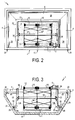
- FIG. 2 is a top view of an embodiment of the apparatus with an integral clarifier at one end and at both sides.
- FIG. 3 is a cross-sectional end on view of an embodiment of the apparatus with an integral clarifier at both sides.
- FIG. 4 is a side view of a mounting frame of the present invention.
- FIG. 5 is a cross-sectional side view of a rotating aerator mounted on a mounting frame inside an embodiment of the apparatus.
- FIG. 1 depicts a cross-sectional side view of waste treatment apparatus 1 (hereinafter “apparatus 1 ”) including aeration basin 2 with integral clarifier 4 at one end.
- Aeration basin 2 comprises rear wall 6 , floor 8 , influent valve 10 and rotating aerator 12 .
- Motor 5 sits atop aeration basin 2 .
- Aeration basin 2 is substantially filled with mixed liquor 14 , which primarily comprises a mixture of influent, sludge and air.
- Clarifier 4 comprises effluent outlet 20 , partition 22 , partition lip 23 , back wall 24 and narrow opening 26 .
- Clarifier 4 contains supernatant 28 and precipitate sludge 30 .
- Motor 5 drives rotating aerator 12 , causing it to rotate.
- Motor 5 is preferably a variable speed electric gear motor, which turns rotating aerator 12 with a chain drive.
- the speed of rotation can be controlled by varying the speed of motor 5 .
- Paddle 17 which extends almost to floor 8 of aeration basin 2 when at the six o'clock position, agitates heavier nonaerated mixed liquor 14 H and sludge that would otherwise collect on floor 8 of aeration basin 2 .
- paddle 17 On its forward downstroke, paddle 17 forces lighter aerated mixed liquor 14 L down toward floor 8 and partition 22 . Some of mixed liquor 14 L enters clarifier 4 through the top portion of narrow opening 26 . The solid particles in that mixed liquor 14 L then settle out to form precipitated sludge 30 . The remaining supernatant water 28 exits through effluent outlet 20 . Precipitated sludge 30 slides down back wall 24 and into aeration basin 2 through the bottom of narrowing opening 26 . Precipitated sludge 30 is eventually moved upwards toward the surface of mixed liquor 14 by force of the rearward upstroke of paddle 17 .
- FIG. 2 is a top view of an embodiment of the apparatus with an integral clarifier 4 at one end and at both sides.
- partition 22 extends around three sides of aeration basin 2 .
- FIG. 2 additionally shows axle 32 , spokes 34 , brackets 35 and mounting frame 36 attached to rotating aerator 12 .
- FIG. 3 is a cross-sectional end on view of an embodiment of the apparatus with an integral clarifier 4 at both sides.
- FIG. 3 shows that each clarifier 4 , or each side of one continuous clarifier 4 , may have a narrow opening 26 .
- FIG. 4 is a side view of a mounting frame 36 A of the present invention.
- Mounting frame 36 A comprises girders 38 attached so as to form an inverted “A.”
- the bearing point 40 for the bearing of rotating aerator 12 (not shown) is located near the lower apex of the inverted “A.”
- the upper edge of the inverted “A” contains a lip 42 that overlaps the top a wall of aeration basin 2 (not shown).
- Fastenings (not shown) maintain mounting frame 36 A in position during revolution of rotating aerator 12 .
- mounting frame 36 A is made of steel and there are two for each rotating aerator 12 (not shown), one on each side.
- Each mounting frame 36 A has one or more lifting points 44 to facilitate the attachment of a sling, hoist or other means of lifting.
- FIG. 5 is a cross-sectional side view of rotating aerator 12 mounted on mounting frames 36 A inside an embodiment of aeration basin 2 .
- FIG. 5 additionally depicts wheel bearings 46 of rotating aerator 12 .
- the invention preferably operates and is further described as follows.
- the apparatus and method can be operated as a hybrid of activated sludge and fixed film processes. Typically, 75-80 percent of the treatment takes place in the activated sludge component and 20-25 percent takes place in the fixed film component.
- the integral clarifier is substantially partitioned from the aeration basin by a partition.
- the partition stops short of the floor, leaving a narrow opening between the clarifier and the aeration basin.
- the back wall of the clarifier that is, the wall opposite the aeration basin, slopes so that the solids and sludge in the clarifier slide toward the bottom of the narrowing opening and into the aeration basin.
- some lighter aerated mixed liquor in the aeration basin enters the clarifier through the top of the narrow opening.
- the narrow opening preferably acts as a two-way door, with sludge going one way through the bottom of the opening and aerated liquor going the other way through the top of the opening. Agitation by the paddle on the rotating aerator forces lighter aerated liquor down near the bottom of the aeration basin. Some of that aerated liquor enters the opening between the aeration basin and clarifier, passing over incoming sludge as it does so. In the clarifier, where there is much less agitation, the solids in the aerated liquor settle to the bottom of the clarifier to form sludge that slides down to the narrow opening and back into the aeration basin. The supernatant liquor or discharge water exits through an outlet or effluent weir, preferably located near the top of the clarifier away from the sludge, and is often further treated with chlorination or oxidation.
- multiple integral clarifiers and hence partitions may be on either or both sides or ends of the aeration basin.
- one clarifier and partition may extend continuously as one piece around all or part of the aeration basin.
- the opening is narrow enough to prevent excessive migration of the mixed liquor from the aeration basin into the clarifier.
- the partition lip inclines toward the clarifier, most preferably at an angle of about 35 degrees. The partition lip helps prevent the paths of the entering mixed liquor and the exiting sludge from conflicting and facilitates a laminar flow of the sludge.
- the partition lip tends to stiffen the partition, which is preferably not supported along its bottom edge.
- the back wall of the clarifier slope at an angle steep enough to direct the sludge through the opening, such as an angle of about 50-65 degrees, most preferably 60 degrees.
- an oxygen probe in the aeration basin may regulate the speed of the rotating aerator to maintain a constant oxygen level.
- the rotating aerator is supported by a mounting frame fastened to the top of the aeration basin.
- a mounting frame fastened to the top of the aeration basin about 70 percent of the rotating aerator, and 100 percent of the mountings and bearings for the central axle, are submersed under the surface of the mixed liquor.
- the rotating aerator and the mountings and bearings for the central axle when mounted on the mounting frame in the aeration basin, the rotating aerator and the mountings and bearings for the central axle are still submersed in the mixed liquor, but the frame itself is fastened to the top of the aeration basin.
- the frame and attached rotating aerator may be removed easily from the aeration basin by a crane or hoist, without removing the mixed liquor from the aeration basin or stopping flow through the plant.
- the rotating aerator may be reinstalled and reattached to the top of the aeration basin.
- the frame is shaped as an inverted “A” with the bearing of the wheel located at the lower apex of the “A.”
- the upper edge of the inverted “A” contains a lip that overlaps the top of the aeration basin.
- Sufficient fastenings, most preferably bolts, must maintain the “A-Frame” in position during revolution of the rotating aerator.
- these frames are made of steel and there are two for each wheel.
- each frame has one or more lifting points to facilitate the attachment of a sling, hoist or other means of lifting the frame from its position on the upper edge of the aeration basin.
- Each pair of frames should be lifted simultaneously to maintain a horizontal position of the rotating aerator during its removal.
- the rotating aerator may even be constructed or erected inside the aeration basin by using the A-frames to support the bearings, or the wheel may be preassembled on the job site or elsewhere. If the rotating aerator is constructed outside of the aeration basin, the A frames can be attached and the rotating aerator lifted into place in the aeration basin.
- Applications of the invention typically include: treatment of domestic and municipal wastewater from 2,000 gallons per day (GPD) to 2 million gallons per day (MPD); treatment of domestic wastewater containing industrial and manufacturing wastes; treatment and pretreatment of high strength organic industrial wastewater; treatment of land fill leachate; combination with septic tanks and lagoons for improved nitrification and biological phosphorous removal; treatment of liquid manure in hog farms, feed lots and animal processing facilities; food processing operations; aerobic sludge stabilization; and aquaculture including fish farming in closed circuit systems.
- GPS gallons per day
- MPD 2 million gallons per day
- the aerating device may not be a rotating aerator-type device.
- an air pump may simply pump air into the aeration basin, thus causing aeration and agitation.
- a fluid pump or propeller might aerate the mixed liquor by throwing it up into the air above the aeration basin.
- the integral clarifier aspect of the invention it is possible to have openings near the middle or top of the partition as well as or instead of at its bottom. In such a case, it is likely that aerated mixed liquor would enter from all openings while sludge would only exit through the bottom opening.
- the clarifier is not structurally integral with the aeration basin, i.e., they do not abut each other or reside in a single main tank body. Rather, they may be only functionally integral. In other words, merely creating a space between the clarifier and aeration basin so that they do not abut one another would not in itself escape the essence of the clarifier feature.
- the clarifier would be functionally integral if a conduit(s) or pipe(s) joining the clarifier and aeration basin allowed the flow of either aerated mixed liquor or sludge, without the means of a pump.
- a conduit(s) or pipe(s) joining the clarifier and aeration basin allowed the flow of either aerated mixed liquor or sludge, without the means of a pump.
- an apparatus or method were substantially the same as the preferred embodiment except that the aerated mixed liquor was pumped from the aeration basin into the clarifier, that apparatus or method would still manifest the inventive clarifier feature.
- an apparatus or method were substantially the same as the preferred embodiment except that the settled sludge was pumped from the clarifier into the aeration basin, it would manifest the inventive clarifier feature.
- nongravity clarifiers may be used.
- the clarifier could use a rotation means to rotate the water and separate the sludge from the discharge water by centrifugal force. In such a case, the sludge could precipitate out against the walls of the clarifier and then slide down the walls toward the opening near the bottom.
Abstract
Description
Claims (21)
Priority Applications (1)
| Application Number | Priority Date | Filing Date | Title |
|---|---|---|---|
| US09/784,032 US6572774B2 (en) | 2001-02-16 | 2001-02-16 | Waste treatment method and apparatus with integral clarifier |
Applications Claiming Priority (1)
| Application Number | Priority Date | Filing Date | Title |
|---|---|---|---|
| US09/784,032 US6572774B2 (en) | 2001-02-16 | 2001-02-16 | Waste treatment method and apparatus with integral clarifier |
Publications (2)
| Publication Number | Publication Date |
|---|---|
| US20020113010A1 US20020113010A1 (en) | 2002-08-22 |
| US6572774B2 true US6572774B2 (en) | 2003-06-03 |
Family
ID=25131135
Family Applications (1)
| Application Number | Title | Priority Date | Filing Date |
|---|---|---|---|
| US09/784,032 Expired - Lifetime US6572774B2 (en) | 2001-02-16 | 2001-02-16 | Waste treatment method and apparatus with integral clarifier |
Country Status (1)
| Country | Link |
|---|---|
| US (1) | US6572774B2 (en) |
Cited By (7)
| Publication number | Priority date | Publication date | Assignee | Title |
|---|---|---|---|---|
| US6949191B1 (en) | 2004-04-29 | 2005-09-27 | Jrj Holdings, Llc | Packaged wastewater treatment unit |
| US7011745B1 (en) * | 2002-07-11 | 2006-03-14 | Moulton Patrick L | Rotating perforated cylinder treatment system |
| US20070084769A1 (en) * | 2002-07-11 | 2007-04-19 | Moulton Patrick L | Rotating perforated cylinder treatment system |
| US7276155B1 (en) | 2006-05-04 | 2007-10-02 | Wastewater Technology, Inc. | Waste treatment apparatus with integral membrane apparatus |
| US20100116734A1 (en) * | 2007-08-01 | 2010-05-13 | Wiemers Reginald A | Biological wastewater treatment apparatus and methods using moving belt contractor |
| US20110180473A1 (en) * | 2008-09-03 | 2011-07-28 | AQ-WISE -WIse Water Technologies Ltd. | Integrated biological wastewater treatment and clarification |
| US9758404B2 (en) | 2014-09-26 | 2017-09-12 | Westech Engineering, Inc. | Methods and apparatuses for adjustable air capture and release |
Families Citing this family (7)
| Publication number | Priority date | Publication date | Assignee | Title |
|---|---|---|---|---|
| KR100428047B1 (en) * | 2001-12-26 | 2004-04-28 | 박석균 | A Waste Water Purifier Using Overflow Sediment and Method |
| US8568593B1 (en) * | 2009-06-02 | 2013-10-29 | Entex Technologies, Inc. | Anoxic system screen scour |
| US10106445B2 (en) * | 2010-02-01 | 2018-10-23 | Jerry L. McKinney | Aerobic treatment/clarifier system for use in an aerobic wastewater treatment system |
| CN104261562B (en) * | 2014-10-13 | 2016-04-27 | 一流清(上海)环保科技有限公司 | Biological bed treatment unit and method under a kind of 360 degree of rotating waters |
| CN107321221B (en) * | 2017-07-11 | 2018-09-07 | 泰州市申泰船业有限公司 | A kind of environmental protection coating material device |
| JP7178808B2 (en) * | 2018-06-25 | 2022-11-28 | 株式会社竹中土木 | Organic wastewater treatment method and treatment system |
| CN112678972B (en) * | 2021-03-11 | 2021-05-28 | 潍坊市市政公用事业服务中心 | Sewage treatment plant is used in municipal administration |
Citations (10)
| Publication number | Priority date | Publication date | Assignee | Title |
|---|---|---|---|---|
| US3339741A (en) * | 1965-01-07 | 1967-09-05 | Degremont | Apparatus for the biological purification of waste water |
| US3385444A (en) * | 1960-04-28 | 1968-05-28 | Dufournet Raymond Edmond | Apparatus for treating sewage |
| US3415378A (en) * | 1966-02-10 | 1968-12-10 | Fukuda Fukuichi | Sewage treatment system |
| US4035290A (en) * | 1973-05-29 | 1977-07-12 | Autotrol Corporation | Method for the treatment of wastewater |
| US4211657A (en) * | 1977-02-16 | 1980-07-08 | Etlin Vladimir N | Means for biological treatment of water |
| US4224155A (en) * | 1975-01-06 | 1980-09-23 | Milne George A | Sewage treatment apparatus |
| US4421648A (en) * | 1981-06-01 | 1983-12-20 | Ferdinand Besik | Apparatus and a method for biological treatment of waste waters |
| US4505813A (en) * | 1982-06-14 | 1985-03-19 | Norwalk Wastewater Equipment Company | Wastewater treatment plant |
| US5316668A (en) * | 1992-12-22 | 1994-05-31 | Jet, Inc. | Wastewater treatment plant and apparatus |
| US6039873A (en) | 1996-02-02 | 2000-03-21 | Staehler; Theo | Process for the thoroughgoing aerobic biological purification of waste water |
-
2001
- 2001-02-16 US US09/784,032 patent/US6572774B2/en not_active Expired - Lifetime
Patent Citations (10)
| Publication number | Priority date | Publication date | Assignee | Title |
|---|---|---|---|---|
| US3385444A (en) * | 1960-04-28 | 1968-05-28 | Dufournet Raymond Edmond | Apparatus for treating sewage |
| US3339741A (en) * | 1965-01-07 | 1967-09-05 | Degremont | Apparatus for the biological purification of waste water |
| US3415378A (en) * | 1966-02-10 | 1968-12-10 | Fukuda Fukuichi | Sewage treatment system |
| US4035290A (en) * | 1973-05-29 | 1977-07-12 | Autotrol Corporation | Method for the treatment of wastewater |
| US4224155A (en) * | 1975-01-06 | 1980-09-23 | Milne George A | Sewage treatment apparatus |
| US4211657A (en) * | 1977-02-16 | 1980-07-08 | Etlin Vladimir N | Means for biological treatment of water |
| US4421648A (en) * | 1981-06-01 | 1983-12-20 | Ferdinand Besik | Apparatus and a method for biological treatment of waste waters |
| US4505813A (en) * | 1982-06-14 | 1985-03-19 | Norwalk Wastewater Equipment Company | Wastewater treatment plant |
| US5316668A (en) * | 1992-12-22 | 1994-05-31 | Jet, Inc. | Wastewater treatment plant and apparatus |
| US6039873A (en) | 1996-02-02 | 2000-03-21 | Staehler; Theo | Process for the thoroughgoing aerobic biological purification of waste water |
Cited By (13)
| Publication number | Priority date | Publication date | Assignee | Title |
|---|---|---|---|---|
| US7011745B1 (en) * | 2002-07-11 | 2006-03-14 | Moulton Patrick L | Rotating perforated cylinder treatment system |
| US20070084769A1 (en) * | 2002-07-11 | 2007-04-19 | Moulton Patrick L | Rotating perforated cylinder treatment system |
| US7491324B2 (en) | 2002-07-11 | 2009-02-17 | Ionic Water Technologies, Inc. | Rotating perforated cylinder treatment system |
| US6949191B1 (en) | 2004-04-29 | 2005-09-27 | Jrj Holdings, Llc | Packaged wastewater treatment unit |
| US20050247623A1 (en) * | 2004-04-29 | 2005-11-10 | Petrone Richard J | Packaged wastewater treatment unit |
| US7077959B2 (en) | 2004-04-29 | 2006-07-18 | Jrj Holding Llc | Packaged wastewater treatment unit |
| US20080017575A1 (en) * | 2006-05-04 | 2008-01-24 | Wastewater Technology, Inc. | Waste treatment method and apparatus with integral membrane apparatus |
| US7276155B1 (en) | 2006-05-04 | 2007-10-02 | Wastewater Technology, Inc. | Waste treatment apparatus with integral membrane apparatus |
| US20100116734A1 (en) * | 2007-08-01 | 2010-05-13 | Wiemers Reginald A | Biological wastewater treatment apparatus and methods using moving belt contractor |
| US8257592B2 (en) * | 2007-08-01 | 2012-09-04 | Rockwater Resource, LLC | Biological wastewater treatment apparatus and methods using moving belt contractor |
| US20110180473A1 (en) * | 2008-09-03 | 2011-07-28 | AQ-WISE -WIse Water Technologies Ltd. | Integrated biological wastewater treatment and clarification |
| US8753511B2 (en) | 2008-09-03 | 2014-06-17 | AQ-WISE—Wise Water Technologies Ltd. | Integrated biological wastewater treatment and clarification |
| US9758404B2 (en) | 2014-09-26 | 2017-09-12 | Westech Engineering, Inc. | Methods and apparatuses for adjustable air capture and release |
Also Published As
| Publication number | Publication date |
|---|---|
| US20020113010A1 (en) | 2002-08-22 |
Similar Documents
| Publication | Publication Date | Title |
|---|---|---|
| US6572774B2 (en) | Waste treatment method and apparatus with integral clarifier | |
| US5874003A (en) | Wastewater treatment apparatus with floating clarifier | |
| US6773593B2 (en) | Continuous flow reactor wastewater treatment plant | |
| US3173866A (en) | Apparatus for the treatment of sewage | |
| FI61019C (en) | BIOLOGISKT FILTER FOER BEHANDLING AV BIOLOGISKT NEDBRYTBARA AVFALLSPRODUKTER INNEHAOLLANDE VAETSKA OCH ANVAENDANDE AV DETSAMMA TILL RENING AV AVFALLSVATTEN | |
| US3788477A (en) | Treatment apparatus | |
| KR101097139B1 (en) | Anoxic/anaerobic bioreactor embedded ciliary ball media | |
| CN1137058C (en) | Biological treating appts. for tannery waste water and for reduction of its sludge | |
| US6613229B2 (en) | Waste treatment method and apparatus with denitrification chamber | |
| JP4002851B2 (en) | Sewage treatment equipment | |
| US4353800A (en) | Method and an apparatus for biological treatment of waste waters | |
| US4940545A (en) | Aerobic waste sludge digester-thickener orbital system and method | |
| US4175041A (en) | Apparatus for degassing floating sludge | |
| US20030183572A1 (en) | Activated sludge method and device for the treatment of effluent with nitrogen and phosphorus removal | |
| KR101192174B1 (en) | Plants for advanced treatment of wastewater | |
| KR101019092B1 (en) | Advanced water-treating apparatus and method for removing phosphorus | |
| JP3802883B2 (en) | Granular sludge production apparatus and production method | |
| US20040045901A1 (en) | Method and apparatus for enhancing wastewater treatment in lagoons | |
| JPH1110193A (en) | Method and apparatus for shared carrier nitrification denitrification reaction | |
| JPH04310298A (en) | Biological nitrogen removing unit | |
| JP7016622B2 (en) | Membrane separation activated sludge treatment equipment and membrane separation activated sludge treatment method | |
| KR100302266B1 (en) | Treatment method of sewage and wastewater using biofilm process and equipment thereof | |
| JPH09253687A (en) | Anaerobic and aerobic treatment apparatus for waste water | |
| KR102315897B1 (en) | Apparatus for treatmenting of Wastewater using semi-batchand | |
| SU931719A1 (en) | Apparatus for biochemically purifying effluents |
Legal Events
| Date | Code | Title | Description |
|---|---|---|---|
| AS | Assignment |
Owner name: WASTEWATER TECHNOLOGY, INC., VIRGINIA Free format text: ASSIGNMENT OF ASSIGNORS INTEREST;ASSIGNOR:RICKETTS, DONALD D.;REEL/FRAME:011559/0045 Effective date: 20010213 |
|
| STCF | Information on status: patent grant |
Free format text: PATENTED CASE |
|
| FPAY | Fee payment |
Year of fee payment: 4 |
|
| AS | Assignment |
Owner name: BANQUE NATIONALE DE CANADA, CANADA Free format text: SECURITY AGREEMENT;ASSIGNOR:WASTEWATER TECHNOLOGY, INC.;REEL/FRAME:021489/0702 Effective date: 20080814 |
|
| AS | Assignment |
Owner name: NATIONAL BANK OF CANADA, CANADA Free format text: SECURITY AGREEMENT;ASSIGNOR:WASTEWATER TECHNOLOGY, INC.;REEL/FRAME:023449/0027 Effective date: 20091002 |
|
| AS | Assignment |
Owner name: MEMBRANE SYSTEMS, INC., CANADA Free format text: MERGER;ASSIGNORS:WASTEWATER TECHNOLOGY, INC.;ITASCA SYSTEMS, INC.;MEMBRANE SYSTEMS, INC.;REEL/FRAME:024672/0248 Effective date: 20100629 |
|
| AS | Assignment |
Owner name: H2O INNOVATION INC., CANADA Free format text: CHANGE OF NAME;ASSIGNOR:MEMBRANE SYSTEMS, INC.;REEL/FRAME:024678/0909 Effective date: 20100629 |
|
| AS | Assignment |
Owner name: H2O INNOVATION USA, INC., CANADA Free format text: CORRECTIVE ASSIGNMENT TO CORRECT THE ASSIGNEE PREVIOUSLY RECORDED ON REEL 024678 FRAME 0909. ASSIGNOR(S) HEREBY CONFIRMS THE ASSIGNEE SHOULD READ "H2O INNOVATION USA, INC.";ASSIGNOR:MEMBRANE SYSTEMS, INC.;REEL/FRAME:024686/0816 Effective date: 20100629 |
|
| FPAY | Fee payment |
Year of fee payment: 8 |
|
| AS | Assignment |
Owner name: NATIONAL BANK OF CANADA, CANADA Free format text: SECURITY AGREEMENT;ASSIGNOR:H20 INNOVATION USA, INC.;REEL/FRAME:033812/0272 Effective date: 20140922 |
|
| FPAY | Fee payment |
Year of fee payment: 12 |
|
| AS | Assignment |
Owner name: BANK OF MONTREAL, CANADA Free format text: SECURITY INTEREST;ASSIGNOR:H2O INNOVATION USA, INC.;REEL/FRAME:035509/0712 Effective date: 20150421 |
|
| AS | Assignment |
Owner name: NATIONAL BANK OF CANADA, CANADA Free format text: RELEASE BY SECURED PARTY;ASSIGNOR:H2O INNOVATION USA, INC.;REEL/FRAME:037890/0412 Effective date: 20160129 |
|
| AS | Assignment |
Owner name: EXPORT DEVELOPMENT CANADA, ONTARIO Free format text: PATENT COLLATERAL AGREEMENT;ASSIGNOR:H2O INNOVATION USA, INC.;REEL/FRAME:039425/0734 Effective date: 20160718 |
|
| AS | Assignment |
Owner name: H2O INNOVATION USA, INC., CANADA Free format text: RELEASE BY SECURED PARTY;ASSIGNOR:BANK OF MONTREAL;REEL/FRAME:049795/0587 Effective date: 20181219 |
|
| FEPP | Fee payment procedure |
Free format text: ENTITY STATUS SET TO UNDISCOUNTED (ORIGINAL EVENT CODE: BIG.); ENTITY STATUS OF PATENT OWNER: LARGE ENTITY |