US6589262B1 - Locking catheter introducing system - Google Patents
Locking catheter introducing system Download PDFInfo
- Publication number
- US6589262B1 US6589262B1 US09/540,712 US54071200A US6589262B1 US 6589262 B1 US6589262 B1 US 6589262B1 US 54071200 A US54071200 A US 54071200A US 6589262 B1 US6589262 B1 US 6589262B1
- Authority
- US
- United States
- Prior art keywords
- dilator
- sheath
- bore
- recited
- introducing apparatus
- Prior art date
- Legal status (The legal status is an assumption and is not a legal conclusion. Google has not performed a legal analysis and makes no representation as to the accuracy of the status listed.)
- Expired - Lifetime
Links
Images


Classifications
-
- A—HUMAN NECESSITIES
- A61—MEDICAL OR VETERINARY SCIENCE; HYGIENE
- A61M—DEVICES FOR INTRODUCING MEDIA INTO, OR ONTO, THE BODY; DEVICES FOR TRANSDUCING BODY MEDIA OR FOR TAKING MEDIA FROM THE BODY; DEVICES FOR PRODUCING OR ENDING SLEEP OR STUPOR
- A61M25/00—Catheters; Hollow probes
- A61M25/01—Introducing, guiding, advancing, emplacing or holding catheters
- A61M25/06—Body-piercing guide needles or the like
- A61M25/0662—Guide tubes
- A61M25/0668—Guide tubes splittable, tear apart
-
- A—HUMAN NECESSITIES
- A61—MEDICAL OR VETERINARY SCIENCE; HYGIENE
- A61M—DEVICES FOR INTRODUCING MEDIA INTO, OR ONTO, THE BODY; DEVICES FOR TRANSDUCING BODY MEDIA OR FOR TAKING MEDIA FROM THE BODY; DEVICES FOR PRODUCING OR ENDING SLEEP OR STUPOR
- A61M29/00—Dilators with or without means for introducing media, e.g. remedies
Definitions
- the present invention relates generally to an introducer and dilator for insertion of medical devices into a patient. More particularly, it pertains to an introducer and dilator which lock together.
- Introducer devices are employed for inserting catheters, guide wires, or other medical devices into patients.
- a typical procedure provides for insertion of a needle into the vasculature of a patient. After insertion of the needle, a guide wire is inserted through the needle, and the needle is removed. The dilator and the sheath are inserted over the guidewire, and the dilator may be removed leaving the sheath protruding from the patient's vein.
- a diagnostic or therapeutic catheter e.g. a central venous access catheter
- guide wire or other medical device is then inserted through the sheath into the patient.
- the dilator and sheath are inserted over the guidewire, and the medical technician is attempting to drive the dilator through the skin, subcutaneous tissue and the wall of the vein, there is a tendency for the dilator to retract toward the sheath.
- the retraction of the dilator can result in trauma to the patient, and can also make the implanting process awkward and imprecise for the medical technician.
- the dilator recedes to a position where the distal end of the dilator is within the sheath, the relatively large sheath causes a puncture at the entry site which is painfully traumatic to the patient. In addition, there are risks of tearing of the tissue adjacent to the entry site.
- U.S. Pat. No. 5,879,333 which relates to a catheter which is snap-fitted with a cannula.
- this type of device allows for the cannula to pop out of the catheter unexpectedly, requiring the medical technician to manually hold the dilator and the sheath together during the insertion process despite the presence of the locking device.
- Another type of locking device is a threaded rotational locking device which locks a dilator to a sheath.
- the threaded fastener is rotated, the dilator also rotates, resulting in complications and/or distraction to the medical technician during the implant procedure. Other distractions can occur when the medical technician uses a device for a first time, and when damage occurs to the device as a result of misuse.
- a locking introducer and dilator which do not become easily and/or unintentionally unlocked from one another during or after insertion into a patient.
- a locking introducer and dilator which do not distract the physician or medical technician during implant.
- An introducing apparatus includes an elongate tubular sheath having an external diameter small enough to be readily insertable in a selected vein.
- the sheath has a bore which receives therein a dilator such that a distal end of the dilator projects from out from the distal end of the sheath.
- a rotatable fastener is rotatably coupled with the dilator, and couples the sheath with the dilator and prevents axial movement therebetween.
- a means of selectively rotating the dilator relative to the sheath includes an anti-rotation member which is associated with the dilator and/or the sheath. The anti-rotation member resists rotational movement of the dilator relative to the sheath as the rotatable fastener is rotated.
- an introducing apparatus in another embodiment, includes an elongate tubular sheath having an external diameter small enough to be readily insertable in a selected vein.
- the sheath has a bore which receives therein a dilator such that a distal end of the dilator projects from out from the distal end of the sheath.
- a rotatable fastener is rotatably coupled with the dilator, and couples the sheath with the dilator and prevents axial movement therebetween.
- a hub of the dilator includes an elliptical cross-section which corresponds to the cross-section of the sheath which resists relative rotational movement between the dilator and the sheath.
- the introducer assembly allows for the medical technician or physician to rotatably lock the sheath and the dilator to one another without unintentionally rotating one relative to the other during the procedure or during the implant. This improves the implanting process and reduces potential pain or damage to the vasculature of the patient. In addition, the medical technician or physician will not become distracted by components inadvertently rotating or by the components separating from each other. A further benefit includes the ability of the introducer apparatus to withstand damage or separation of the sheath should the medical technician apply excessive torque to the dilator, whether intentional or unintentional. Furthermore, the introducer apparatus allows for the dilator to selectively rotatable without any damage occurring to the sheath and/or the dilator.
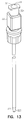
- FIG. 1 is a side elevational view illustrating an introducer apparatus constructed in accordance with one embodiment.
- FIG. 2 is a top plan view illustrating a sheath of the introducer apparatus constructed in accordance with one embodiment.
- FIG. 3 is a cross-sectional view illustrating a sheath of the introducer apparatus constructed in accordance with one embodiment.
- FIG. 4 is a perspective view illustrating a dilator of the introducer apparatus constructed in accordance with one embodiment.
- FIG. 5 is a side elevational view illustrating a portion of the dilator of the introducer apparatus constructed in accordance with one embodiment.
- FIG. 6 is a top plan view illustrating a portion of the dilator of the introducer apparatus constructed in accordance with one embodiment.
- FIG. 7 is a side elevational view illustrating a portion of the dilator of the introducer apparatus constructed in accordance with one embodiment.
- FIG. 8 is a cross-sectional view illustrating a dilator coupled with a sheath constructed in accordance with one embodiment.
- FIG. 9 is a cross-sectional view illustrating a dilator coupled with a sheath constructed in accordance with one embodiment.
- FIG. 10 is a cross-sectional view illustrating a dilator coupled with a sheath constructed in accordance with one embodiment.
- FIG. 11 is a cross-sectional view illustrating a dilator coupled with a sheath constructed in accordance with one embodiment.
- FIG. 12 is a side elevational view illustrating an introducer apparatus constructed in accordance with one embodiment.
- FIG. 13 is a perspective view illustrating a dilator of the introducer apparatus constructed in accordance with one embodiment.
- FIG. 14 is a side elevational view illustrating a portion of the dilator of the introducer apparatus constructed in accordance with one embodiment.
- FIG. 15 is a cross-sectional view illustrating a dilator coupled with a sheath constructed in accordance with one embodiment.
- FIG. 16 is a cross-sectional view illustrating a dilator coupled with a sheath constructed in accordance with one embodiment.
- FIG. 17 is a cross-sectional view illustrating a dilator coupled with a sheath constructed in accordance with one embodiment.
- FIG. 18 is a cross-sectional view illustrating a dilator coupled with a sheath constructed in accordance with one embodiment.
- FIG. 19 is a cross-sectional view illustrating a dilator coupled with a sheath constructed in accordance with one embodiment.
- An introducer assembly 100 as shown in FIG. 1, is described herein which includes generally a sheath 140 and a dilator 120 .
- the dilator 120 allows for the introducer assembly 100 to be introduced into a vein of a patient, for instance, over a guidewire.
- the dilator 120 extends from a distal end 122 to a proximal end 124 , where the distal end 122 is insertable into a patient.
- the distal end 122 optionally ends in a tapered end 123 .
- a hub 126 having a bore 128 therethrough. Extending from the hub 126 to the distal end 122 is a generally cylindrical portion 130 .
- the dilator 120 also includes a passage 121 therethrough, aligned with the bore 128 , which allows the dilator 120 to be inserted over a guidewire or a catheter.
- the dilator 120 is sized to be received by the sheath 140 therein.
- the sheath 140 allows for additional instruments to be inserted therethrough and inserted into the patient.
- the sheath 140 includes various types of sheaths, for instance, the sheath 140 can comprise a sheath which has a strengthening braid of material. Alternatively, the sheath 140 includes those which are modified to prevent bends in the elongate sheath.
- the sheath 140 extends from a distal end 142 to a proximal end 148 , where the distal end 142 is first inserted into the patient and the proximal end 148 remains outside of the patient. Near the distal end 142 is a tapered portion 144 which provides a transition to a cylindrical portion 146 .
- the sheath 140 also includes a passage therethrough which allows for the introduction of the dilator 120 therein.
- the sheath 140 includes at least one tab 210 which extends radially outward from the sheath 140 .
- the sheath 140 includes two tabs 220 which are disposed 180 degrees from each other. Disposed between the two tabs 220 are tab break lines 222 .
- the sheath 140 is splittable such that the sheath 140 is separable into two or more components.
- the sheath 140 is separable or splittable which prevents disruption to or removal of instruments or devices which have been inserted through the sheath 140 .
- the splittable sheath 140 is splittable in a number of manners such as including at least one score line 141 .
- the sheath 140 is externally scored, and optionally two scores 141 are 180 degrees from each other.
- the scores 141 are aligned with the tab break lines 222 such that the tab break lines 222 and the scores 141 are disposed between the two tabs 220 .
- the sheath 140 is splittable using a slitting device, a rip cord or strengthening strip running along the longitudinal length of the sheath, a weakening which allows the introducer to be ripped apart, or other techniques which are also to those skilled in the art.
- the sheath 140 includes anti-rotation features which prevent the dilator 120 from rotating relative to the sheath 140 .
- the anti-rotation features include at least one flat 150 disposed within an inner diameter 146 of the sheath 140 , as shown in FIGS. 2 and 3.
- the anti-rotation features include two flats 152 .
- the two flats 152 are sized and positioned to be optionally placed adjacent to anti-rotation features.
- Other variations on the anti-rotation features are discussed below.
- At the proximal end 148 of the sheath 140 is a sheath hub 160 to which the dilator 120 is coupled, as further discussed below.
- the sheath hub 160 includes a lip 162 which facilitates coupling of the dilator 120 thereto.
- the anti-rotation features of the sheath 140 are disposed only within the sheath hub 160 .
- the dilator 120 includes a rotatable fastener 134 (shown in a cut-away view) rotatably coupled therewith.
- the rotatable fastener 134 allows for coupling of the dilator 120 to the sheath 140 such that axial movement between the dilator 120 and sheath 140 is prevented.
- the rotatable fastener 134 includes a threaded portion which threadingly engages with the lip 162 of the sheath hub 160 .
- the dilator 120 also shown in FIGS. 4-7, includes a dilator hub 126 .
- the dilator 120 also includes anti-rotation features.
- the anti-rotation features are disposed on a coupling portion 129 of the dilator 120 .
- the anti-rotation features include a flat 136 on the coupling portion 129 of the dilator 120 , as shown in FIGS. 5-7.
- two flats 137 are included on the coupling portion 129 of the dilator 120 .
- the two flats 137 are disposed adjacent to the sheath flats 152 of the introducer apparatus 100 such that, when assembled, the dilator 120 does not rotate relative to the sheath 140 .
- FIGS. 8-11 Other embodiments of the anti-rotation features of the sheath 140 and/or the dilator 120 are shown in FIGS. 8-11, where a cross-section is shown of the coupling portion 129 of the dilator 120 disposed within the sheath hub 160 of the sheath 140 .
- FIG. 8 illustrates a dilator 120 having a single dilator flat 170 and a sheath 140 having a single sheath flat 172 .
- the dilator flat 170 is disposed adjacent the sheath flat 172 .
- FIG. 9 illustrates a dilator 120 having two dilator flats 174 and a sheath 140 having two sheath flats 176 .
- the two dilator flats 174 are disposed adjacent the two sheath flats 176 . It should be noted that more than two flats can be used and is considered within the scope of the invention.
- FIG. 10 illustrates another embodiment which includes a coupling portion of the dilator 120 having an elliptical cross-section 180 disposed within a sheath 140 , where the inner diameter 182 of the sheath has an elliptical cross-section 184 .
- FIG. 11 illustrates yet another alternative.
- the dilator 120 includes at least one projection 188 , for instance the dilator 120 includes two projections 190 which project outward from an external surface 192 of the dilator 120 .
- the sheath 140 includes at least one recess 194 , for instance, two recesses 196 .
- the recesses are sized and positioned on the inner diameter 182 of the sheath 140 to receive therein the two projections 190 of the dilator 120 .
- the two projections 190 of the dilator 120 are disposed within the recesses 196 of the sheath 140 .
- the distal end 122 of the dilator 120 is disposed within the sheath 140 until the dilator hub 126 is proximate to the proximal end 148 of the sheath 140 .
- the rotatable fastener 134 is pressed against the lip 162 of the sheath 140 and the rotatable fastener 134 is rotated.
- the fastener 134 is rotated, the dilator 120 becomes further inserted into the sheath 140 , and becomes axially fixed to the sheath 140 as the threads engage the lip 162 of the sheath 140 .
- the anti-rotation features of the dilator 120 and/or the sheath 140 become seated such that further rotation of the rotatable fastener 134 does not cause rotation of the dilator 120 relative to the sheath 140 , even when the fastener 134 is rotated to remove the axial fixation of the dilator 120 relative to the sheath 140 .
- FIG. 12 illustrates another embodiment which shows an introducer assembly 300 including generally a sheath 340 and a dilator 320 .
- a user can selectively choose whether the sheath 340 and the dilator 320 rotate relative to one another, for instance, as a rotatable fastener is rotated.
- the dilator 320 as shown in more detail in FIG. 13, allows for the introducer assembly 300 to be introduced into a vein of a patient, for instance, over a guidewire.
- the dilator 320 extends from a distal end 322 to a proximal end 324 , where the distal end 322 is insertable into a patient.
- the distal end 322 optionally ends in a tapered end 323 .
- a hub 326 having a bore 328 therethrough. Extending from the hub 326 to the distal end 322 is a generally cylindrical portion 330 .
- the dilator 320 also includes a passage 321 therethrough, aligned with the bore 328 , which allows the dilator 320 to be inserted over a guidewire or a catheter.
- the dilator 320 is sized to be received by the sheath 340 therein.
- the sheath 340 includes various types of sheaths, for instance, the sheath 340 can comprise a sheath which has a strengthening braid of material. Alternatively, the sheath 340 includes those which are modified to prevent bends in the elongate sheath.
- the sheath 340 extends from a distal end 342 to a proximal end 348 , where the distal end 342 is first inserted into the patient and the proximal end 348 remains outside of the patient. Near the distal end 342 of the sheath 340 is a tapered portion 344 which provides a transition to a cylindrical portion 346 .
- the sheath 340 also includes a passage therethrough which allows for the introduction of the dilator 320 therein. After the introducer assembly 300 has been inserted into a patient, and the dilator 320 is removed, other medical instruments can be easily inserted into and through the sheath 340 , and introduced into the patient.
- the sheath 340 includes at least one tab 410 which extends radially outward from the sheath 340 .
- the sheath 340 includes two tabs 420 which are optionally disposed 180 degrees from each other. Disposed between the two tabs 420 are tab break lines 422 .
- the sheath 340 is splittable such that the sheath 340 is separable into two or more components.
- the sheath 340 is separable or splittable which prevents disruption to or removal of instruments or devices which have been inserted through the sheath 340 .
- the splittable sheath 340 is splittable in a number of manners such as including at least one score line 341 .
- the sheath 340 is externally scored, and optionally two scores 341 are 180 degrees from each other.
- the scores 341 are aligned with the tab break lines 422 such that the tab break lines 422 and the scores 341 are disposed between the two tabs 420 .
- the sheath 340 is splittable using a slitting device, a rip cord or strengthening strip running along the longitudinal length of the sheath, a weakening which allows the introducer to be ripped apart, or other techniques which are also to those skilled in the art.
- the sheath 340 includes anti-rotation features which resist and optionally prevent the dilator 320 from rotating relative to the sheath 340 .
- additional features allow for the anti-rotation features to be overcome, such that the user can selectively rotate the dilator 320 or can selectively lock the rotational movement of the dilator 320 .
- the anti-rotation features include at least one flat 350 disposed within an inner diameter of the sheath 340 , as shown in FIG. 15, which illustrates a cross-section of the dilator 320 coupled with the sheath 340 .
- the anti-rotation features include two flats.
- the dilator 320 also includes at least one flat 352 , which is disposed adjacent to the sheath flat 350 when the sheath 340 and dilator 320 are locked.
- the dilator 320 includes rounded edges 354 on the flats 352 .
- the sheath 340 includes rounded corners 356 .
- the rounded edges 354 and the rounded corners 356 allow for a user to overcome the anti-rotation feature without damage to the sheath 340 or the dilator 320 or without unintentional separation of the sheath portions.
- the rounded portions of the dilator and/or sheath could alternatively include tapered edges. Other variations on the anti-rotation features are discussed below.
- a sheath hub 360 to which the dilator 320 is coupled, as further discussed below.
- the sheath hub 360 includes a lip 362 which facilitates coupling of the dilator 320 thereto, such that the dilator 320 can be locked to prevent axial movement between the dilator 320 and the sheath 340 .
- the anti-rotation features of the sheath 340 are disposed only within the sheath hub 360 .
- the dilator 320 includes a rotatable fastener 334 (shown in a cut-away view) rotatably coupled therewith.
- the rotatable fastener 334 allows for coupling of the dilator 320 to the sheath 340 such that axial movement between the dilator 320 and sheath 340 is prevented.
- the rotatable fastener 334 includes a threaded portion which threadingly engages with the lip 362 of the sheath hub 360 .
- the dilator 320 also shown in FIGS. 13 and 14, includes a dilator hub 326 .
- the dilator 320 also includes anti-rotation features.
- the anti-rotation features are optionally disposed only on the hub 329 of the dilator 320 .
- the hub 329 has an elliptical shape (FIG. 10) which corresponds to the shape of the sheath 340 .
- FIGS. 15-19 Other embodiments of the anti-rotation features of the sheath 340 and/or the dilator 320 are shown in FIGS. 15-19, where a cross-section is shown of the hub 326 of the dilator 320 disposed within the sheath hub 360 of the sheath 340 .
- dilator 320 having a single dilator flat 352 and a sheath 340 having a single sheath flat 350 .
- the dilator flat 352 is disposed adjacent the sheath flat 350 . It should be noted that more than two flats can be used and is considered within the scope of the invention.
- FIG. 16 illustrates another embodiment.
- the dilator 320 includes at least one projection 388 , for instance the dilator 320 includes two projections 390 which project outward from an external surface 392 of the dilator 320 .
- the projections 390 are adapted to fold about a hinge point 391 , such that a selection can be made whether to have the dilator 320 remain in an anti-rotative position or not.
- the sheath 340 includes at least one recess 394 , for instance, two recesses 396 .
- the recesses are sized and positioned on the inner diameter 382 of the sheath 340 to receive therein the two projections 390 of the dilator 320 .
- the projections 390 include a tapered edge 387 and the recesses 396 include a tapered edge 389 .
- the two projections 390 of the dilator 320 are disposed within the recesses 396 of the sheath 340 .
- FIGS. 17 and 18 illustrate another embodiment.
- the dilator 320 includes projections 390 similar to that discussed above, although in addition to or in alternative to the hinge point, the projections 390 are collapsible.
- the projections 390 are formed of collapsible material such as foam.
- FIG. 17 illustrates the projections 390 disposed within the recesses 396 of the sheath 340 in an uncollapsed position. Should the medical technician choose to selectively override these anti-rotation features, the technician applies additional torque which forces the projections to compress, as shown in FIG. 18 .
- FIG. 19 illustrates another embodiment of the introducer apparatus.
- the dilator 320 includes projections 390 similar to that discussed above, although in addition to or in alternative to the hinge point, the projections 390 are adapted to break away from the dilator 320 .
- the projections 390 break away from the external surface 392 of the dilator 320 along a break line 399 .
- the break line 399 can be formed by a score line, for example, or a perforated line.
- FIG. 19 illustrates the projections 390 disposed within the recesses 396 of the sheath 340 , prior to the projections 390 being broken away from the dilator 320 . Should the medical technician choose to selectively override these anti-rotation features, the technician applies additional torque which forces the projections 390 to break away from the dilator 320 .
- the distal end 322 of the dilator 320 is disposed within the sheath 340 until the dilator hub 326 is proximate to the proximal end 348 of the sheath 340 .
- the rotatable fastener 334 is pressed against the lip 362 of the sheath 340 and the rotatable fastener 334 is rotated.
- the fastener 334 is rotated, the dilator 320 becomes further inserted into the sheath 340 , and becomes axially fixed to the sheath 340 as the threads engage the lip 362 of the sheath 340 .
- the anti-rotation features of the dilator 320 and/or the sheath 340 become seated such that further rotation of the rotatable fastener 334 does not cause rotation of the dilator 320 relative to the sheath 340 , even when the fastener 334 is rotated to remove the axial fixation of the dilator 320 relative to the sheath 340 .
- the technician further rotates the dilator 320 relative to the sheath 340 by applying additional torque to unseat the anti rotation features.
- the introducer assembly allows for the medical technician or physician to rotatably lock the sheath and the dilator to one another without inadvertently rotating one relative to the other during the procedure or during the implant.
- This improves the implanting process and reduces potential pain or damage to the vasculature of the patient.
- the medical technician or physician will not become distracted by components inadvertently rotating or by the components inadvertently separating from each other.
- the medical technician can optionally rotate the dilator should they choose to do so without distraction, or without any damage to the sheath or the dilator, or without inadvertently separating a severable sheath.
Abstract
Description
Claims (20)
Priority Applications (1)
| Application Number | Priority Date | Filing Date | Title |
|---|---|---|---|
| US09/540,712 US6589262B1 (en) | 2000-03-31 | 2000-03-31 | Locking catheter introducing system |
Applications Claiming Priority (1)
| Application Number | Priority Date | Filing Date | Title |
|---|---|---|---|
| US09/540,712 US6589262B1 (en) | 2000-03-31 | 2000-03-31 | Locking catheter introducing system |
Publications (1)
| Publication Number | Publication Date |
|---|---|
| US6589262B1 true US6589262B1 (en) | 2003-07-08 |
Family
ID=24156616
Family Applications (1)
| Application Number | Title | Priority Date | Filing Date |
|---|---|---|---|
| US09/540,712 Expired - Lifetime US6589262B1 (en) | 2000-03-31 | 2000-03-31 | Locking catheter introducing system |
Country Status (1)
| Country | Link |
|---|---|
| US (1) | US6589262B1 (en) |
Cited By (106)
| Publication number | Priority date | Publication date | Assignee | Title |
|---|---|---|---|---|
| US20030055483A1 (en) * | 2001-08-23 | 2003-03-20 | Gumm Darrell C. | Rotating stent delivery system for side branch access and protection and method of using same |
| US6712789B1 (en) * | 2000-07-13 | 2004-03-30 | Medamicus, Inc. | Introducer having a movable valve assembly with removable side port |
| US20040098020A1 (en) * | 2002-08-29 | 2004-05-20 | Medical Components, Inc. | Releasably locking dilator and sheath assembly |
| US20040172119A1 (en) * | 2003-02-27 | 2004-09-02 | Scimed Life Systems, Inc. | Rotating balloon expandable sheath bifurcation delivery |
| US20040172121A1 (en) * | 2003-02-27 | 2004-09-02 | Tracee Eidenschink | Rotating balloon expandable sheath bifurcation delivery |
| US20050038494A1 (en) * | 2003-08-15 | 2005-02-17 | Scimed Life Systems, Inc. | Clutch driven stent delivery system |
| US20050049628A1 (en) * | 2002-08-29 | 2005-03-03 | Medical Components, Inc. | Releasably locking dilator and sheath assembly |
| US20050149161A1 (en) * | 2003-12-29 | 2005-07-07 | Tracee Eidenschink | Edge protection and bifurcated stent delivery system |
| US20050154442A1 (en) * | 2004-01-13 | 2005-07-14 | Tracee Eidenschink | Bifurcated stent delivery system |
| US20050182473A1 (en) * | 2004-02-18 | 2005-08-18 | Tracee Eidenschink | Multi stent delivery system |
| US20050192608A1 (en) * | 2003-10-17 | 2005-09-01 | Miguel Moreno | Surgical access device and manufacture thereof |
| US20050245874A1 (en) * | 2002-11-20 | 2005-11-03 | Vygon | Device for locoregional anesthesia and method for making the cannula of said device |
| US20050267487A1 (en) * | 2004-04-30 | 2005-12-01 | Christensen Mark A | Valved sheath introducer for venous cannulation |
| US20050273149A1 (en) * | 2004-06-08 | 2005-12-08 | Tran Thomas T | Bifurcated stent delivery system |
| US20050277909A1 (en) * | 2004-06-14 | 2005-12-15 | Mcdaniel Benjamin D | Catheter grip |
| US20060004398A1 (en) * | 2004-07-02 | 2006-01-05 | Binder Lawrence J Jr | Sequential dilator system |
| US20060058738A1 (en) * | 2004-09-14 | 2006-03-16 | Ponzi Dean M | Catheter clamp |
| US20060217664A1 (en) * | 2004-11-15 | 2006-09-28 | Hattler Brack G | Telescoping vascular dilator |
| US20070050006A1 (en) * | 2005-08-31 | 2007-03-01 | Cook Ireland Limited | Coaxial dilatation method for stent implantation |
| US20070078446A1 (en) * | 2005-08-31 | 2007-04-05 | Cook Ireland Limited And Cook Incorporated | Stent for implantation |
| EP1786493A2 (en) * | 2004-08-17 | 2007-05-23 | Arrow International, Inc. | Over-the- needle peel-away sheath catheter introducer |
| US20070276466A1 (en) * | 2005-08-31 | 2007-11-29 | Vance Products Inc., D/B/A/ Cook Urological Inc. | Stent for implantation |
| WO2009002828A2 (en) * | 2007-06-22 | 2008-12-31 | Medical Components, Inc. | Tearaway sheath assembly with hemostasis valve |
| US20090088771A1 (en) * | 2007-09-19 | 2009-04-02 | William Cook Europe, Aps | Implant deployment device |
| US20090143739A1 (en) * | 2007-09-18 | 2009-06-04 | Medical Components, Inc | Tearaway sheath assembly with split hemostasis valve |
| US20090234290A1 (en) * | 2008-03-14 | 2009-09-17 | Medical Components, Inc. | Tearaway Introducer Sheath with Hemostasis Valve |
| WO2009157927A1 (en) * | 2008-06-25 | 2009-12-30 | I-Flow Corporation | Soft tissue tunneling device |
| US20100010445A1 (en) * | 2004-03-18 | 2010-01-14 | C. R. Bard, Inc. | Connector system for a proximally trimmable catheter |
| US7744619B2 (en) | 2004-02-24 | 2010-06-29 | Boston Scientific Scimed, Inc. | Rotatable catheter assembly |
| CN101128158B (en) * | 2004-09-29 | 2010-10-13 | 新特斯有限责任公司 | Less invasive surgical system and methods |
| US7854731B2 (en) | 2004-03-18 | 2010-12-21 | C. R. Bard, Inc. | Valved catheter |
| US7875019B2 (en) | 2005-06-20 | 2011-01-25 | C. R. Bard, Inc. | Connection system for multi-lumen catheter |
| US7922740B2 (en) | 2004-02-24 | 2011-04-12 | Boston Scientific Scimed, Inc. | Rotatable catheter assembly |
| US20110230859A1 (en) * | 2008-07-14 | 2011-09-22 | Lumen Biomedical, Inc. | Aspiration catheters for thrombus removal |
| US8083728B2 (en) | 2004-03-18 | 2011-12-27 | C. R. Bard, Inc. | Multifunction adaptor for an open-ended catheter |
| US8133199B2 (en) | 2008-08-27 | 2012-03-13 | Boston Scientific Scimed, Inc. | Electroactive polymer activation system for a medical device |
| US8177771B2 (en) | 2004-03-18 | 2012-05-15 | C. R. Bard, Inc. | Catheter connector |
| US8177770B2 (en) | 2004-04-01 | 2012-05-15 | C. R. Bard, Inc. | Catheter connector system |
| US8216295B2 (en) | 2008-07-01 | 2012-07-10 | Endologix, Inc. | Catheter system and methods of using same |
| US8235942B2 (en) | 2005-05-04 | 2012-08-07 | Olympus Endo Technology America Inc. | Rotate-to-advance catheterization system |
| US8317678B2 (en) | 2005-05-04 | 2012-11-27 | Olympus Endo Technology America Inc. | Rotate-to-advance catheterization system |
| US8333003B2 (en) | 2008-05-19 | 2012-12-18 | Boston Scientific Scimed, Inc. | Bifurcation stent crimping systems and methods |
| US8337484B2 (en) | 2009-06-26 | 2012-12-25 | C. R. Band, Inc. | Proximally trimmable catheter including pre-attached bifurcation and related methods |
| US8343040B2 (en) | 2005-05-04 | 2013-01-01 | Olympus Endo Technology America Inc. | Rotate-to-advance catheterization system |
| US8366674B2 (en) | 2005-05-04 | 2013-02-05 | Olympus Endo Technology America Inc. | Rotate-to-advance catheterization system |
| US8377041B2 (en) | 2005-02-28 | 2013-02-19 | Olympus Endo Technology America Inc. | Rotate-to-advance catheterization system |
| US8403890B2 (en) | 2004-11-29 | 2013-03-26 | C. R. Bard, Inc. | Reduced friction catheter introducer and method of manufacturing and using the same |
| US8414477B2 (en) | 2005-05-04 | 2013-04-09 | Olympus Endo Technology America Inc. | Rotate-to-advance catheterization system |
| US8435229B2 (en) | 2006-02-28 | 2013-05-07 | Olympus Endo Technology America Inc. | Rotate-to-advance catheterization system |
| US20130190783A1 (en) * | 2007-03-15 | 2013-07-25 | Insighlra Medical, Inc. | Fibrotic band interrupter and implant introducing device |
| US20130226094A1 (en) * | 2012-02-28 | 2013-08-29 | Cook Medical Technologies Llc | Introducer assembly |
| US8574220B2 (en) | 2006-02-28 | 2013-11-05 | Olympus Endo Technology America Inc. | Rotate-to-advance catheterization system |
| US8608702B2 (en) | 2007-10-19 | 2013-12-17 | C. R. Bard, Inc. | Introducer including shaped distal region |
| US8672889B2 (en) | 2006-05-05 | 2014-03-18 | Kimberly-Clark Worldwide, Inc. | Soft tissue tunneling device |
| US8764631B2 (en) | 1997-02-10 | 2014-07-01 | Olympus Endo Technology America Inc. | Rotate to advance catheterization system |
| US8777841B2 (en) | 2007-05-18 | 2014-07-15 | Olympus Endo Technology America Inc. | Rotate-to-advance catheterization system |
| US8926564B2 (en) | 2004-11-29 | 2015-01-06 | C. R. Bard, Inc. | Catheter introducer including a valve and valve actuator |
| US8932260B2 (en) | 2004-11-29 | 2015-01-13 | C. R. Bard, Inc. | Reduced-friction catheter introducer and method of manufacturing and using the same |
| US9220395B2 (en) | 1999-09-27 | 2015-12-29 | James J. Frassica | Rotate-to-advance catheterization system |
| US9289232B2 (en) | 2006-05-05 | 2016-03-22 | Avent, Inc. | Soft tissue tunneling device |
| US9387009B2 (en) | 2007-10-05 | 2016-07-12 | DePuy Synthes Products, Inc. | Dilation system and method of using the same |
| US9498356B2 (en) | 2012-12-19 | 2016-11-22 | Cook Medical Technologies, LLC | Flexible stent and delivery system |
| US9522254B2 (en) | 2013-01-30 | 2016-12-20 | Vascular Pathways, Inc. | Systems and methods for venipuncture and catheter placement |
| US9549835B2 (en) | 2011-03-01 | 2017-01-24 | Endologix, Inc. | Catheter system and methods of using same |
| US9597483B2 (en) | 2004-11-29 | 2017-03-21 | C. R. Bard, Inc. | Reduced-friction catheter introducer and method of manufacturing and using the same |
| US9616201B2 (en) | 2011-01-31 | 2017-04-11 | Vascular Pathways, Inc. | Intravenous catheter and insertion device with reduced blood spatter |
| US9675784B2 (en) | 2007-04-18 | 2017-06-13 | Vascular Pathways, Inc. | Intravenous catheter insertion and blood sample devices and method of use |
| US9713695B2 (en) | 2013-05-30 | 2017-07-25 | Intermountain Invention Management, Llc | Devices for creation of multiple vascular access sites |
| US9763814B2 (en) | 2014-10-24 | 2017-09-19 | Cook Medical Technologies Llc | Elongate medical device |
| US9820761B2 (en) | 2014-03-21 | 2017-11-21 | Route 92 Medical, Inc. | Rapid aspiration thrombectomy system and method |
| US9861792B2 (en) | 2011-02-25 | 2018-01-09 | C. R. Bard, Inc. | Medical component insertion device including a retractable needle |
| US9872971B2 (en) | 2010-05-14 | 2018-01-23 | C. R. Bard, Inc. | Guidewire extension system for a catheter placement device |
| US9950139B2 (en) | 2010-05-14 | 2018-04-24 | C. R. Bard, Inc. | Catheter placement device including guidewire and catheter control elements |
| WO2019027966A1 (en) * | 2017-07-31 | 2019-02-07 | Boston Scientific Scimed, Inc. | Dilator with engagement region |
| US10213582B2 (en) | 2013-12-23 | 2019-02-26 | Route 92 Medical, Inc. | Methods and systems for treatment of acute ischemic stroke |
| US10220191B2 (en) | 2005-07-06 | 2019-03-05 | Vascular Pathways, Inc. | Intravenous catheter insertion device and method of use |
| US10232146B2 (en) | 2014-09-05 | 2019-03-19 | C. R. Bard, Inc. | Catheter insertion device including retractable needle |
| US10384039B2 (en) | 2010-05-14 | 2019-08-20 | C. R. Bard, Inc. | Catheter insertion device including top-mounted advancement components |
| US10420919B2 (en) | 2015-04-24 | 2019-09-24 | Cook Medical Technologies Llc | Introducer with dynamic dilator and methods of using the same |
| US10426931B2 (en) | 2010-05-14 | 2019-10-01 | C. R. Bard, Inc. | Catheter placement device and method |
| US10456555B2 (en) | 2015-02-04 | 2019-10-29 | Route 92 Medical, Inc. | Rapid aspiration thrombectomy system and method |
| US10478535B2 (en) | 2017-05-24 | 2019-11-19 | Mivi Neuroscience, Inc. | Suction catheter systems for applying effective aspiration in remote vessels, especially cerebral arteries |
| US10493262B2 (en) | 2016-09-12 | 2019-12-03 | C. R. Bard, Inc. | Blood control for a catheter insertion device |
| US20200147351A1 (en) * | 2007-04-18 | 2020-05-14 | Asspv, Llc | Access device |
| US10716915B2 (en) | 2015-11-23 | 2020-07-21 | Mivi Neuroscience, Inc. | Catheter systems for applying effective suction in remote vessels and thrombectomy procedures facilitated by catheter systems |
| USD903101S1 (en) | 2011-05-13 | 2020-11-24 | C. R. Bard, Inc. | Catheter |
| USD903100S1 (en) | 2015-05-01 | 2020-11-24 | C. R. Bard, Inc. | Catheter placement device |
| US11020133B2 (en) | 2017-01-10 | 2021-06-01 | Route 92 Medical, Inc. | Aspiration catheter systems and methods of use |
| USD921884S1 (en) | 2018-07-27 | 2021-06-08 | Bard Access Systems, Inc. | Catheter insertion device |
| US11040176B2 (en) | 2015-05-15 | 2021-06-22 | C. R. Bard, Inc. | Catheter placement device including an extensible needle safety component |
| US11065019B1 (en) | 2015-02-04 | 2021-07-20 | Route 92 Medical, Inc. | Aspiration catheter systems and methods of use |
| US11129737B2 (en) | 2015-06-30 | 2021-09-28 | Endologix Llc | Locking assembly for coupling guidewire to delivery system |
| US11224449B2 (en) | 2015-07-24 | 2022-01-18 | Route 92 Medical, Inc. | Anchoring delivery system and methods |
| US11229770B2 (en) | 2018-05-17 | 2022-01-25 | Route 92 Medical, Inc. | Aspiration catheter systems and methods of use |
| US11229445B2 (en) | 2016-10-06 | 2022-01-25 | Mivi Neuroscience, Inc. | Hydraulic displacement and removal of thrombus clots, and catheters for performing hydraulic displacement |
| US11234723B2 (en) | 2017-12-20 | 2022-02-01 | Mivi Neuroscience, Inc. | Suction catheter systems for applying effective aspiration in remote vessels, especially cerebral arteries |
| USRE49056E1 (en) | 2007-01-24 | 2022-05-03 | Smiths Medical Asd, Inc. | Access device |
| US11389626B2 (en) | 2018-03-07 | 2022-07-19 | Bard Access Systems, Inc. | Guidewire advancement and blood flashback systems for a medical device insertion system |
| US11400260B2 (en) | 2017-03-01 | 2022-08-02 | C. R. Bard, Inc. | Catheter insertion device |
| US11471647B2 (en) | 2014-11-07 | 2022-10-18 | C. R. Bard, Inc. | Connection system for tunneled catheters |
| US11559665B2 (en) | 2019-08-19 | 2023-01-24 | Becton, Dickinson And Company | Midline catheter placement device |
| US11617865B2 (en) | 2020-01-24 | 2023-04-04 | Mivi Neuroscience, Inc. | Suction catheter systems with designs allowing rapid clearing of clots |
| US11813418B2 (en) | 2019-08-22 | 2023-11-14 | Becton, Dickinson And Company | Echogenic balloon dilation catheter and balloon thereof |
| US11871944B2 (en) | 2011-08-05 | 2024-01-16 | Route 92 Medical, Inc. | Methods and systems for treatment of acute ischemic stroke |
| US11896782B2 (en) | 2017-08-23 | 2024-02-13 | C. R. Bard, Inc. | Priming and tunneling system for a retrograde catheter assembly |
| US11925779B2 (en) | 2010-05-14 | 2024-03-12 | C. R. Bard, Inc. | Catheter insertion device including top-mounted advancement components |
Citations (28)
| Publication number | Priority date | Publication date | Assignee | Title |
|---|---|---|---|---|
| US4233974A (en) | 1978-09-05 | 1980-11-18 | Baxter Travenol Laboratories, Inc. | Spinal needle assembly |
| US4345606A (en) | 1977-12-13 | 1982-08-24 | Littleford Philip O | Split sleeve introducers for pacemaker electrodes and the like |
| US4596559A (en) | 1984-11-02 | 1986-06-24 | Fleischhacker John J | Break-away handle for a catheter introducer set |
| US4682981A (en) * | 1984-08-07 | 1987-07-28 | Terumo Kabushiki Kaisha | Medical device |
| US4772266A (en) * | 1987-05-04 | 1988-09-20 | Catheter Technology Corp. | Catheter dilator/sheath assembly and method |
| US4929236A (en) | 1988-05-26 | 1990-05-29 | Shiley Infusaid, Inc. | Snap-lock fitting catheter for an implantable device |
| US4966588A (en) | 1986-07-25 | 1990-10-30 | H. G. Wallace Limited | Device suitable for the administration of a therapeutic substance |
| US5064414A (en) | 1989-07-28 | 1991-11-12 | Angeion Corporation | Locking clip with sheath and dilator |
| US5098392A (en) | 1991-06-28 | 1992-03-24 | Fleischhacker John J | Locking dilator for peel away introducer sheath |
| US5141497A (en) | 1989-06-06 | 1992-08-25 | Becton, Dickinson And Company | Apparatus and method for an introducer |
| US5160323A (en) | 1989-05-26 | 1992-11-03 | Andrew Daniel E | Method and system for inserting spinal catheters |
| US5171222A (en) | 1988-03-10 | 1992-12-15 | Scimed Life Systems, Inc. | Interlocking peel-away dilation catheter |
| US5250033A (en) | 1992-10-28 | 1993-10-05 | Interventional Thermodynamics, Inc. | Peel-away introducer sheath having proximal fitting |
| US5255691A (en) | 1991-11-13 | 1993-10-26 | Medtronic, Inc. | Percutaneous epidural lead introducing system and method |
| US5275583A (en) * | 1992-10-05 | 1994-01-04 | Lawrence Crainich | Trocar assembly with independently acting shield means |
| US5279597A (en) | 1992-01-13 | 1994-01-18 | Arrow International Investment Corp. | Catheter compression clamp |
| US5290294A (en) | 1990-04-17 | 1994-03-01 | Brian Cox | Method and apparatus for removal of a foreign body cavity |
| US5304142A (en) | 1992-08-04 | 1994-04-19 | Medamicus, Inc. | Dilator - Introducer locking hub and sheath valve apparatus |
| US5320602A (en) | 1993-05-14 | 1994-06-14 | Wilson-Cook Medical, Inc. | Peel-away endoscopic retrograde cholangio pancreatography catheter and a method for using the same |
| US5391152A (en) * | 1993-03-12 | 1995-02-21 | C. R. Bard, Inc. | Catheter interlock assembly |
| US5437645A (en) | 1993-10-08 | 1995-08-01 | United States Surgical Corporation | Surgical instrument positioning device |
| US5454790A (en) * | 1994-05-09 | 1995-10-03 | Innerdyne, Inc. | Method and apparatus for catheterization access |
| US5741233A (en) | 1995-10-20 | 1998-04-21 | Tfx Medical, Incorporated | Introducer device and methods of use thereof |
| US5782807A (en) | 1995-10-20 | 1998-07-21 | Tfx Medical Incorporated | Releasably locking introducer devices |
| US5827227A (en) * | 1996-07-17 | 1998-10-27 | Delago; Augustin J. | Catheter having a radially adjustable sheath |
| US5879333A (en) | 1995-04-24 | 1999-03-09 | Microcatheters Pty Ltd | Catheter with body locking into cannula hub |
| US5885217A (en) * | 1995-01-20 | 1999-03-23 | Tyco Group S.A.R.L. | Catheter introducer |
| US6120494A (en) | 1998-01-23 | 2000-09-19 | Medtronic, Inc. | Method of placing a cannula |
-
2000
- 2000-03-31 US US09/540,712 patent/US6589262B1/en not_active Expired - Lifetime
Patent Citations (28)
| Publication number | Priority date | Publication date | Assignee | Title |
|---|---|---|---|---|
| US4345606A (en) | 1977-12-13 | 1982-08-24 | Littleford Philip O | Split sleeve introducers for pacemaker electrodes and the like |
| US4233974A (en) | 1978-09-05 | 1980-11-18 | Baxter Travenol Laboratories, Inc. | Spinal needle assembly |
| US4682981A (en) * | 1984-08-07 | 1987-07-28 | Terumo Kabushiki Kaisha | Medical device |
| US4596559A (en) | 1984-11-02 | 1986-06-24 | Fleischhacker John J | Break-away handle for a catheter introducer set |
| US4966588A (en) | 1986-07-25 | 1990-10-30 | H. G. Wallace Limited | Device suitable for the administration of a therapeutic substance |
| US4772266A (en) * | 1987-05-04 | 1988-09-20 | Catheter Technology Corp. | Catheter dilator/sheath assembly and method |
| US5171222A (en) | 1988-03-10 | 1992-12-15 | Scimed Life Systems, Inc. | Interlocking peel-away dilation catheter |
| US4929236A (en) | 1988-05-26 | 1990-05-29 | Shiley Infusaid, Inc. | Snap-lock fitting catheter for an implantable device |
| US5160323A (en) | 1989-05-26 | 1992-11-03 | Andrew Daniel E | Method and system for inserting spinal catheters |
| US5141497A (en) | 1989-06-06 | 1992-08-25 | Becton, Dickinson And Company | Apparatus and method for an introducer |
| US5064414A (en) | 1989-07-28 | 1991-11-12 | Angeion Corporation | Locking clip with sheath and dilator |
| US5290294A (en) | 1990-04-17 | 1994-03-01 | Brian Cox | Method and apparatus for removal of a foreign body cavity |
| US5098392A (en) | 1991-06-28 | 1992-03-24 | Fleischhacker John J | Locking dilator for peel away introducer sheath |
| US5255691A (en) | 1991-11-13 | 1993-10-26 | Medtronic, Inc. | Percutaneous epidural lead introducing system and method |
| US5279597A (en) | 1992-01-13 | 1994-01-18 | Arrow International Investment Corp. | Catheter compression clamp |
| US5304142A (en) | 1992-08-04 | 1994-04-19 | Medamicus, Inc. | Dilator - Introducer locking hub and sheath valve apparatus |
| US5275583A (en) * | 1992-10-05 | 1994-01-04 | Lawrence Crainich | Trocar assembly with independently acting shield means |
| US5250033A (en) | 1992-10-28 | 1993-10-05 | Interventional Thermodynamics, Inc. | Peel-away introducer sheath having proximal fitting |
| US5391152A (en) * | 1993-03-12 | 1995-02-21 | C. R. Bard, Inc. | Catheter interlock assembly |
| US5320602A (en) | 1993-05-14 | 1994-06-14 | Wilson-Cook Medical, Inc. | Peel-away endoscopic retrograde cholangio pancreatography catheter and a method for using the same |
| US5437645A (en) | 1993-10-08 | 1995-08-01 | United States Surgical Corporation | Surgical instrument positioning device |
| US5454790A (en) * | 1994-05-09 | 1995-10-03 | Innerdyne, Inc. | Method and apparatus for catheterization access |
| US5885217A (en) * | 1995-01-20 | 1999-03-23 | Tyco Group S.A.R.L. | Catheter introducer |
| US5879333A (en) | 1995-04-24 | 1999-03-09 | Microcatheters Pty Ltd | Catheter with body locking into cannula hub |
| US5741233A (en) | 1995-10-20 | 1998-04-21 | Tfx Medical, Incorporated | Introducer device and methods of use thereof |
| US5782807A (en) | 1995-10-20 | 1998-07-21 | Tfx Medical Incorporated | Releasably locking introducer devices |
| US5827227A (en) * | 1996-07-17 | 1998-10-27 | Delago; Augustin J. | Catheter having a radially adjustable sheath |
| US6120494A (en) | 1998-01-23 | 2000-09-19 | Medtronic, Inc. | Method of placing a cannula |
Cited By (225)
| Publication number | Priority date | Publication date | Assignee | Title |
|---|---|---|---|---|
| US8764631B2 (en) | 1997-02-10 | 2014-07-01 | Olympus Endo Technology America Inc. | Rotate to advance catheterization system |
| US9220395B2 (en) | 1999-09-27 | 2015-12-29 | James J. Frassica | Rotate-to-advance catheterization system |
| US6712789B1 (en) * | 2000-07-13 | 2004-03-30 | Medamicus, Inc. | Introducer having a movable valve assembly with removable side port |
| US20040176744A1 (en) * | 2000-07-13 | 2004-09-09 | Medamicus, Inc. | Introducer having a movable valve assembly with removable side port |
| US8211137B2 (en) | 2001-08-23 | 2012-07-03 | Gumm Darrel C | Rotating stent delivery system for side branch access and protection and method of using same |
| US20030055483A1 (en) * | 2001-08-23 | 2003-03-20 | Gumm Darrell C. | Rotating stent delivery system for side branch access and protection and method of using same |
| US7563270B2 (en) | 2001-08-23 | 2009-07-21 | Gumm Darrel C | Rotating stent delivery system for side branch access and protection and method of using same |
| US9248261B2 (en) | 2002-08-29 | 2016-02-02 | Medical Components, Inc. | Releasably locking dilator and sheath assembly |
| US20050049628A1 (en) * | 2002-08-29 | 2005-03-03 | Medical Components, Inc. | Releasably locking dilator and sheath assembly |
| US7422571B2 (en) | 2002-08-29 | 2008-09-09 | Medical Components, Inc. | Releasably locking dilator and sheath assembly |
| US6796991B2 (en) * | 2002-08-29 | 2004-09-28 | Medical Components, Inc. | Releasably locking dilator and sheath assembly |
| US20040098020A1 (en) * | 2002-08-29 | 2004-05-20 | Medical Components, Inc. | Releasably locking dilator and sheath assembly |
| US20050245874A1 (en) * | 2002-11-20 | 2005-11-03 | Vygon | Device for locoregional anesthesia and method for making the cannula of said device |
| US20040172121A1 (en) * | 2003-02-27 | 2004-09-02 | Tracee Eidenschink | Rotating balloon expandable sheath bifurcation delivery |
| US20040172119A1 (en) * | 2003-02-27 | 2004-09-02 | Scimed Life Systems, Inc. | Rotating balloon expandable sheath bifurcation delivery |
| US8784472B2 (en) | 2003-08-15 | 2014-07-22 | Boston Scientific Scimed, Inc. | Clutch driven stent delivery system |
| US20050038494A1 (en) * | 2003-08-15 | 2005-02-17 | Scimed Life Systems, Inc. | Clutch driven stent delivery system |
| US20050192608A1 (en) * | 2003-10-17 | 2005-09-01 | Miguel Moreno | Surgical access device and manufacture thereof |
| US7892170B2 (en) | 2003-10-17 | 2011-02-22 | Tyco Healthcare Group Lp | Surgical access device and manufacture thereof |
| US8708898B2 (en) | 2003-10-17 | 2014-04-29 | Covidien Lp | Surgical access device and manufacture thereof |
| US20110174425A1 (en) * | 2003-10-17 | 2011-07-21 | Tyco Healthcare Group Lp | Surgical access device and manufacture thereof |
| US20050149161A1 (en) * | 2003-12-29 | 2005-07-07 | Tracee Eidenschink | Edge protection and bifurcated stent delivery system |
| US7686841B2 (en) | 2003-12-29 | 2010-03-30 | Boston Scientific Scimed, Inc. | Rotating balloon expandable sheath bifurcation delivery system |
| US7922753B2 (en) | 2004-01-13 | 2011-04-12 | Boston Scientific Scimed, Inc. | Bifurcated stent delivery system |
| US20050154442A1 (en) * | 2004-01-13 | 2005-07-14 | Tracee Eidenschink | Bifurcated stent delivery system |
| US8012192B2 (en) | 2004-02-18 | 2011-09-06 | Boston Scientific Scimed, Inc. | Multi-stent delivery system |
| US20050182473A1 (en) * | 2004-02-18 | 2005-08-18 | Tracee Eidenschink | Multi stent delivery system |
| US7744619B2 (en) | 2004-02-24 | 2010-06-29 | Boston Scientific Scimed, Inc. | Rotatable catheter assembly |
| US7922740B2 (en) | 2004-02-24 | 2011-04-12 | Boston Scientific Scimed, Inc. | Rotatable catheter assembly |
| US8333784B2 (en) | 2004-02-24 | 2012-12-18 | Boston Scientific Scimed, Inc. | Rotatable catheter assembly |
| US8083728B2 (en) | 2004-03-18 | 2011-12-27 | C. R. Bard, Inc. | Multifunction adaptor for an open-ended catheter |
| US7883502B2 (en) | 2004-03-18 | 2011-02-08 | C. R. Bard, Inc. | Connector system for a proximally trimmable catheter |
| US8523840B2 (en) | 2004-03-18 | 2013-09-03 | C. R. Bard, Inc. | Connector system for a proximally trimmable catheter |
| US8177771B2 (en) | 2004-03-18 | 2012-05-15 | C. R. Bard, Inc. | Catheter connector |
| US20100010445A1 (en) * | 2004-03-18 | 2010-01-14 | C. R. Bard, Inc. | Connector system for a proximally trimmable catheter |
| US7854731B2 (en) | 2004-03-18 | 2010-12-21 | C. R. Bard, Inc. | Valved catheter |
| US8177770B2 (en) | 2004-04-01 | 2012-05-15 | C. R. Bard, Inc. | Catheter connector system |
| US9108033B2 (en) | 2004-04-30 | 2015-08-18 | C. R. Bard, Inc. | Valved sheath introducer for venous cannulation |
| US8720065B2 (en) | 2004-04-30 | 2014-05-13 | C. R. Bard, Inc. | Valved sheath introducer for venous cannulation |
| US20050267487A1 (en) * | 2004-04-30 | 2005-12-01 | Christensen Mark A | Valved sheath introducer for venous cannulation |
| US7637893B2 (en) * | 2004-04-30 | 2009-12-29 | C. R. Bard, Inc. | Valved sheath introducer for venous cannulation |
| US10307182B2 (en) | 2004-04-30 | 2019-06-04 | C. R. Bard, Inc. | Valved sheath introducer for venous cannulation |
| US20050273149A1 (en) * | 2004-06-08 | 2005-12-08 | Tran Thomas T | Bifurcated stent delivery system |
| US20080119923A1 (en) * | 2004-06-08 | 2008-05-22 | Scimed Life Systems, Inc. | Bifurcated stent delivery system |
| US7628783B2 (en) * | 2004-06-14 | 2009-12-08 | Biosense Webster, Inc. | Catheter grip |
| US20050277909A1 (en) * | 2004-06-14 | 2005-12-15 | Mcdaniel Benjamin D | Catheter grip |
| US20060267063A1 (en) * | 2004-06-14 | 2006-11-30 | Biosense Webster, Inc. | Catheter grip |
| US7104982B2 (en) | 2004-06-14 | 2006-09-12 | Biosense Webster Inc | Catheter grip |
| US20060004398A1 (en) * | 2004-07-02 | 2006-01-05 | Binder Lawrence J Jr | Sequential dilator system |
| EP1786493A4 (en) * | 2004-08-17 | 2010-03-31 | Arrow Int Inc | Over-the- needle peel-away sheath catheter introducer |
| EP1786493A2 (en) * | 2004-08-17 | 2007-05-23 | Arrow International, Inc. | Over-the- needle peel-away sheath catheter introducer |
| US7776017B2 (en) | 2004-09-14 | 2010-08-17 | Biosense Webster, Inc. | Catheter clamp |
| US20060058738A1 (en) * | 2004-09-14 | 2006-03-16 | Ponzi Dean M | Catheter clamp |
| CN101128158B (en) * | 2004-09-29 | 2010-10-13 | 新特斯有限责任公司 | Less invasive surgical system and methods |
| US20060217664A1 (en) * | 2004-11-15 | 2006-09-28 | Hattler Brack G | Telescoping vascular dilator |
| US9283351B2 (en) | 2004-11-29 | 2016-03-15 | C. R. Bard, Inc. | Reduced friction catheter introducer and method of manufacturing and using the same |
| US8926564B2 (en) | 2004-11-29 | 2015-01-06 | C. R. Bard, Inc. | Catheter introducer including a valve and valve actuator |
| US10398879B2 (en) | 2004-11-29 | 2019-09-03 | C. R. Bard, Inc. | Reduced-friction catheter introducer and method of manufacturing and using the same |
| US8403890B2 (en) | 2004-11-29 | 2013-03-26 | C. R. Bard, Inc. | Reduced friction catheter introducer and method of manufacturing and using the same |
| US9597483B2 (en) | 2004-11-29 | 2017-03-21 | C. R. Bard, Inc. | Reduced-friction catheter introducer and method of manufacturing and using the same |
| US9278188B2 (en) | 2004-11-29 | 2016-03-08 | C. R. Bard, Inc. | Catheter introducer including a valve and valve actuator |
| US9101737B2 (en) | 2004-11-29 | 2015-08-11 | C. R. Bard, Inc. | Reduced friction catheter introducer and method of manufacturing and using the same |
| US9078998B2 (en) | 2004-11-29 | 2015-07-14 | C. R. Bard, Inc. | Catheter introducer including a valve and valve actuator |
| US8932260B2 (en) | 2004-11-29 | 2015-01-13 | C. R. Bard, Inc. | Reduced-friction catheter introducer and method of manufacturing and using the same |
| US8377041B2 (en) | 2005-02-28 | 2013-02-19 | Olympus Endo Technology America Inc. | Rotate-to-advance catheterization system |
| US8317678B2 (en) | 2005-05-04 | 2012-11-27 | Olympus Endo Technology America Inc. | Rotate-to-advance catheterization system |
| US8747300B2 (en) | 2005-05-04 | 2014-06-10 | Olympus Endo Technology America Inc. | Rotate-to-advance catheterization system |
| US8414477B2 (en) | 2005-05-04 | 2013-04-09 | Olympus Endo Technology America Inc. | Rotate-to-advance catheterization system |
| US8235942B2 (en) | 2005-05-04 | 2012-08-07 | Olympus Endo Technology America Inc. | Rotate-to-advance catheterization system |
| US8366674B2 (en) | 2005-05-04 | 2013-02-05 | Olympus Endo Technology America Inc. | Rotate-to-advance catheterization system |
| US8343040B2 (en) | 2005-05-04 | 2013-01-01 | Olympus Endo Technology America Inc. | Rotate-to-advance catheterization system |
| US8852168B2 (en) | 2005-06-20 | 2014-10-07 | C. R. Bard, Inc. | Connection system for multi-lumen catheter |
| US8617138B2 (en) | 2005-06-20 | 2013-12-31 | C. R. Bard, Inc. | Connection system for multi-lumen catheter |
| US8206376B2 (en) | 2005-06-20 | 2012-06-26 | C. R. Bard, Inc. | Connection system for multi-lumen catheter |
| US7875019B2 (en) | 2005-06-20 | 2011-01-25 | C. R. Bard, Inc. | Connection system for multi-lumen catheter |
| US10220191B2 (en) | 2005-07-06 | 2019-03-05 | Vascular Pathways, Inc. | Intravenous catheter insertion device and method of use |
| US10912930B2 (en) | 2005-07-06 | 2021-02-09 | Vascular Pathways, Inc. | Intravenous catheter insertion device and method of use |
| US10806906B2 (en) | 2005-07-06 | 2020-10-20 | Vascular Pathways, Inc. | Intravenous catheter insertion device and method of use |
| US11925778B2 (en) | 2005-07-06 | 2024-03-12 | Vascular Pathways, Inc. | Intravenous catheter insertion device |
| US11020571B2 (en) | 2005-07-06 | 2021-06-01 | Vascular Pathways, Inc. | Intravenous catheter insertion device and method of use |
| US11577054B2 (en) | 2005-07-06 | 2023-02-14 | Vascular Pathways, Inc. | Intravenous catheter insertion device and method of use |
| US7789915B2 (en) | 2005-08-31 | 2010-09-07 | Vance Products Incorporated | Stent for implantation |
| US20070078446A1 (en) * | 2005-08-31 | 2007-04-05 | Cook Ireland Limited And Cook Incorporated | Stent for implantation |
| US20070276466A1 (en) * | 2005-08-31 | 2007-11-29 | Vance Products Inc., D/B/A/ Cook Urological Inc. | Stent for implantation |
| US20070050006A1 (en) * | 2005-08-31 | 2007-03-01 | Cook Ireland Limited | Coaxial dilatation method for stent implantation |
| US7550012B2 (en) | 2005-08-31 | 2009-06-23 | Cook Ireland Limited | Stent for implantation |
| US8435229B2 (en) | 2006-02-28 | 2013-05-07 | Olympus Endo Technology America Inc. | Rotate-to-advance catheterization system |
| US8574220B2 (en) | 2006-02-28 | 2013-11-05 | Olympus Endo Technology America Inc. | Rotate-to-advance catheterization system |
| US9289232B2 (en) | 2006-05-05 | 2016-03-22 | Avent, Inc. | Soft tissue tunneling device |
| US8672889B2 (en) | 2006-05-05 | 2014-03-18 | Kimberly-Clark Worldwide, Inc. | Soft tissue tunneling device |
| USRE49056E1 (en) | 2007-01-24 | 2022-05-03 | Smiths Medical Asd, Inc. | Access device |
| US20170281924A1 (en) * | 2007-03-15 | 2017-10-05 | Giuseppe Amato | Fibrotic band interrupter and implant introducing device |
| US20130190783A1 (en) * | 2007-03-15 | 2013-07-25 | Insighlra Medical, Inc. | Fibrotic band interrupter and implant introducing device |
| US9757540B2 (en) | 2007-04-18 | 2017-09-12 | Vascular Pathways, Inc. | Intravenous catheter insertion and blood sample devices and method of use |
| US9675784B2 (en) | 2007-04-18 | 2017-06-13 | Vascular Pathways, Inc. | Intravenous catheter insertion and blood sample devices and method of use |
| US11291804B2 (en) | 2007-04-18 | 2022-04-05 | Smiths Medical Asd, Inc. | Access device |
| US20200147351A1 (en) * | 2007-04-18 | 2020-05-14 | Asspv, Llc | Access device |
| US10525236B2 (en) | 2007-05-07 | 2020-01-07 | Vascular Pathways, Inc. | Intravenous catheter insertion and blood sample devices and method of use |
| US10799680B2 (en) | 2007-05-07 | 2020-10-13 | Vascular Pathways, Inc. | Intravenous catheter insertion and blood sample devices and method of use |
| US10086171B2 (en) | 2007-05-07 | 2018-10-02 | Vascular Pathways, Inc. | Intravenous catheter insertion and blood sample devices and method of use |
| US8870755B2 (en) | 2007-05-18 | 2014-10-28 | Olympus Endo Technology America Inc. | Rotate-to-advance catheterization system |
| US8777841B2 (en) | 2007-05-18 | 2014-07-15 | Olympus Endo Technology America Inc. | Rotate-to-advance catheterization system |
| US8298189B2 (en) | 2007-06-22 | 2012-10-30 | Medical Components, Inc. | Hemostasis valve |
| US20100234807A1 (en) * | 2007-06-22 | 2010-09-16 | Medical Components, Inc. | Hemostasis valve |
| US20100241083A1 (en) * | 2007-06-22 | 2010-09-23 | Medical Components, Inc. | Hub for tearaway sheath assembly |
| US7744571B2 (en) | 2007-06-22 | 2010-06-29 | Medical Components, Inc. | Tearaway sheath assembly with hemostasis valve |
| WO2009002828A3 (en) * | 2007-06-22 | 2009-02-19 | Medical Components Inc | Tearaway sheath assembly with hemostasis valve |
| US8147456B2 (en) | 2007-06-22 | 2012-04-03 | Medical Components, Inc. | Hub for tearaway sheath assembly |
| US20090018508A1 (en) * | 2007-06-22 | 2009-01-15 | Medical Components, Inc. | Tearaway Sheath Assembly with Hemostasis Valve |
| WO2009002828A2 (en) * | 2007-06-22 | 2008-12-31 | Medical Components, Inc. | Tearaway sheath assembly with hemostasis valve |
| US8523822B2 (en) | 2007-09-18 | 2013-09-03 | Medical Components, Inc. | Tearaway sheath assembly with split hemostasis valve seal |
| US20090143739A1 (en) * | 2007-09-18 | 2009-06-04 | Medical Components, Inc | Tearaway sheath assembly with split hemostasis valve |
| US8273059B2 (en) | 2007-09-18 | 2012-09-25 | Medical Components, Inc. | Tearaway sheath assembly with split hemostasis valve seal |
| US8382715B2 (en) | 2007-09-18 | 2013-02-26 | Medical Components, Inc. | Tearaway sheath assembly with split hemostasis valve seal |
| US20100292647A1 (en) * | 2007-09-18 | 2010-11-18 | Medical Components, Inc. | Valve-Retaining Cap for Tearaway Sheath Assembly and Method of Assembly |
| US20100292646A1 (en) * | 2007-09-18 | 2010-11-18 | Medical Components, Inc. | Tearaway Sheath Assembly with Split Hemostasis Valve Seal |
| US20090088771A1 (en) * | 2007-09-19 | 2009-04-02 | William Cook Europe, Aps | Implant deployment device |
| US9044266B2 (en) * | 2007-09-19 | 2015-06-02 | Cook Medical Technologies Llc | Implant deployment device |
| US11737743B2 (en) | 2007-10-05 | 2023-08-29 | DePuy Synthes Products, Inc. | Dilation system and method of using the same |
| US10925594B2 (en) | 2007-10-05 | 2021-02-23 | DePuy Synthes Products, Inc. | Dilation system and method of using the same |
| US9974533B2 (en) | 2007-10-05 | 2018-05-22 | DePuy Synthes Products, Inc. | Dilation system and method of using the same |
| US9387009B2 (en) | 2007-10-05 | 2016-07-12 | DePuy Synthes Products, Inc. | Dilation system and method of using the same |
| US10194895B2 (en) | 2007-10-05 | 2019-02-05 | DePuy Synhes Products, Inc. | Dilation system and method of using the same |
| US9737290B2 (en) | 2007-10-05 | 2017-08-22 | DePuy Synthes Products, Inc. | Dilation system and method of using the same |
| US8608702B2 (en) | 2007-10-19 | 2013-12-17 | C. R. Bard, Inc. | Introducer including shaped distal region |
| US20090234290A1 (en) * | 2008-03-14 | 2009-09-17 | Medical Components, Inc. | Tearaway Introducer Sheath with Hemostasis Valve |
| US20100331784A1 (en) * | 2008-03-14 | 2010-12-30 | Medical Components, Inc. | Tearaway Introducer Sheath with Hemostasis Valve |
| US8105287B2 (en) | 2008-03-14 | 2012-01-31 | Medical Components, Inc. | Tearaway introducer sheath with hemostasis valve |
| US7938806B2 (en) | 2008-03-14 | 2011-05-10 | Medical Components, Inc. | Tearaway introducer sheath with hemostasis valve |
| US8333003B2 (en) | 2008-05-19 | 2012-12-18 | Boston Scientific Scimed, Inc. | Bifurcation stent crimping systems and methods |
| WO2009157927A1 (en) * | 2008-06-25 | 2009-12-30 | I-Flow Corporation | Soft tissue tunneling device |
| US8216295B2 (en) | 2008-07-01 | 2012-07-10 | Endologix, Inc. | Catheter system and methods of using same |
| US9700701B2 (en) | 2008-07-01 | 2017-07-11 | Endologix, Inc. | Catheter system and methods of using same |
| US10512758B2 (en) | 2008-07-01 | 2019-12-24 | Endologix, Inc. | Catheter system and methods of using same |
| US9662129B2 (en) | 2008-07-14 | 2017-05-30 | Medtronic Inc. | Aspiration catheters for thrombus removal |
| US9532792B2 (en) | 2008-07-14 | 2017-01-03 | Medtronic, Inc. | Aspiration catheters for thrombus removal |
| US8070694B2 (en) | 2008-07-14 | 2011-12-06 | Medtronic Vascular, Inc. | Fiber based medical devices and aspiration catheters |
| US10058339B2 (en) | 2008-07-14 | 2018-08-28 | Medtronic, Inc. | Aspiration catheters for thrombus removal |
| US10952757B2 (en) | 2008-07-14 | 2021-03-23 | Medtronic, Inc. | Aspiration catheters for thrombus removal |
| US20110230859A1 (en) * | 2008-07-14 | 2011-09-22 | Lumen Biomedical, Inc. | Aspiration catheters for thrombus removal |
| US8133199B2 (en) | 2008-08-27 | 2012-03-13 | Boston Scientific Scimed, Inc. | Electroactive polymer activation system for a medical device |
| US8337484B2 (en) | 2009-06-26 | 2012-12-25 | C. R. Band, Inc. | Proximally trimmable catheter including pre-attached bifurcation and related methods |
| US10688280B2 (en) | 2010-05-14 | 2020-06-23 | C. R. Bard, Inc. | Catheter placement device including guidewire and catheter control elements |
| US11278702B2 (en) | 2010-05-14 | 2022-03-22 | C. R. Bard, Inc. | Guidewire extension system for a catheter placement device |
| US10688281B2 (en) | 2010-05-14 | 2020-06-23 | C. R. Bard, Inc. | Catheter placement device including guidewire and catheter control elements |
| US10384039B2 (en) | 2010-05-14 | 2019-08-20 | C. R. Bard, Inc. | Catheter insertion device including top-mounted advancement components |
| US9950139B2 (en) | 2010-05-14 | 2018-04-24 | C. R. Bard, Inc. | Catheter placement device including guidewire and catheter control elements |
| US11000678B2 (en) | 2010-05-14 | 2021-05-11 | C. R. Bard, Inc. | Catheter placement device and method |
| US10426931B2 (en) | 2010-05-14 | 2019-10-01 | C. R. Bard, Inc. | Catheter placement device and method |
| US10722685B2 (en) | 2010-05-14 | 2020-07-28 | C. R. Bard, Inc. | Catheter placement device including guidewire and catheter control elements |
| US9872971B2 (en) | 2010-05-14 | 2018-01-23 | C. R. Bard, Inc. | Guidewire extension system for a catheter placement device |
| US11925779B2 (en) | 2010-05-14 | 2024-03-12 | C. R. Bard, Inc. | Catheter insertion device including top-mounted advancement components |
| US11135406B2 (en) | 2010-05-14 | 2021-10-05 | C. R. Bard, Inc. | Catheter insertion device including top-mounted advancement components |
| US11202886B2 (en) | 2011-01-31 | 2021-12-21 | Vascular Pathways, Inc. | Intravenous catheter and insertion device with reduced blood spatter |
| US9616201B2 (en) | 2011-01-31 | 2017-04-11 | Vascular Pathways, Inc. | Intravenous catheter and insertion device with reduced blood spatter |
| US10328239B2 (en) | 2011-01-31 | 2019-06-25 | Vascular Pathways, Inc. | Intravenous catheter and insertion device with reduced blood spatter |
| US11123524B2 (en) | 2011-02-25 | 2021-09-21 | C. R. Bard, Inc. | Medical component insertion device including a retractable needle |
| US9861792B2 (en) | 2011-02-25 | 2018-01-09 | C. R. Bard, Inc. | Medical component insertion device including a retractable needle |
| US11931534B2 (en) | 2011-02-25 | 2024-03-19 | C. R. Bard, Inc. | Medical component insertion device including a retractable needle |
| US10660775B2 (en) | 2011-03-01 | 2020-05-26 | Endologix, Inc. | Catheter system and methods of using same |
| US9687374B2 (en) | 2011-03-01 | 2017-06-27 | Endologix, Inc. | Catheter system and methods of using same |
| US9549835B2 (en) | 2011-03-01 | 2017-01-24 | Endologix, Inc. | Catheter system and methods of using same |
| USD903101S1 (en) | 2011-05-13 | 2020-11-24 | C. R. Bard, Inc. | Catheter |
| US11871944B2 (en) | 2011-08-05 | 2024-01-16 | Route 92 Medical, Inc. | Methods and systems for treatment of acute ischemic stroke |
| EP2633828A3 (en) * | 2012-02-28 | 2014-08-27 | Cook Medical Technologies LLC | Introducer assembly |
| US20130226094A1 (en) * | 2012-02-28 | 2013-08-29 | Cook Medical Technologies Llc | Introducer assembly |
| US9498356B2 (en) | 2012-12-19 | 2016-11-22 | Cook Medical Technologies, LLC | Flexible stent and delivery system |
| US10265507B2 (en) | 2013-01-30 | 2019-04-23 | Vascular Pathways, Inc. | Systems and methods for venipuncture and catheter placement |
| US9522254B2 (en) | 2013-01-30 | 2016-12-20 | Vascular Pathways, Inc. | Systems and methods for venipuncture and catheter placement |
| US9713695B2 (en) | 2013-05-30 | 2017-07-25 | Intermountain Invention Management, Llc | Devices for creation of multiple vascular access sites |
| US10213582B2 (en) | 2013-12-23 | 2019-02-26 | Route 92 Medical, Inc. | Methods and systems for treatment of acute ischemic stroke |
| US11534575B2 (en) | 2013-12-23 | 2022-12-27 | Route 92 Medical, Inc. | Methods and systems for treatment of acute ischemic stroke |
| US10471233B2 (en) | 2013-12-23 | 2019-11-12 | Route 92 Medical, Inc. | Methods and systems for treatment of acute ischemic stroke |
| US11318282B2 (en) | 2013-12-23 | 2022-05-03 | Route 92 Medical, Inc. | Methods and systems for treatment of acute ischemic stroke |
| US10864351B2 (en) | 2013-12-23 | 2020-12-15 | Route 92 Medical, Inc. | Methods and systems for treatment of acute ischemic stroke |
| US10569049B2 (en) | 2013-12-23 | 2020-02-25 | Route 92 Medical, Inc. | Methods and systems for treatment of acute ischemic stroke |
| US9820761B2 (en) | 2014-03-21 | 2017-11-21 | Route 92 Medical, Inc. | Rapid aspiration thrombectomy system and method |
| US10232146B2 (en) | 2014-09-05 | 2019-03-19 | C. R. Bard, Inc. | Catheter insertion device including retractable needle |
| US11033719B2 (en) | 2014-09-05 | 2021-06-15 | C. R. Bard, Inc. | Catheter insertion device including retractable needle |
| US11565089B2 (en) | 2014-09-05 | 2023-01-31 | C. R. Bard, Inc. | Catheter insertion device including retractable needle |
| US9763814B2 (en) | 2014-10-24 | 2017-09-19 | Cook Medical Technologies Llc | Elongate medical device |
| US11471647B2 (en) | 2014-11-07 | 2022-10-18 | C. R. Bard, Inc. | Connection system for tunneled catheters |
| US11793972B2 (en) | 2015-02-04 | 2023-10-24 | Route 92 Medical, Inc. | Rapid aspiration thrombectomy system and method |
| US11633571B2 (en) | 2015-02-04 | 2023-04-25 | Route 92 Medical, Inc. | Rapid aspiration thrombectomy system and method |
| US11224450B2 (en) | 2015-02-04 | 2022-01-18 | Route 92 Medical, Inc. | Aspiration catheter systems and methods of use |
| US11806032B2 (en) | 2015-02-04 | 2023-11-07 | Route 92 Medical, Inc. | Aspiration catheter systems and methods of use |
| US11224721B2 (en) | 2015-02-04 | 2022-01-18 | Route 92 Medical, Inc. | Rapid aspiration thrombectomy system and method |
| US11793529B2 (en) | 2015-02-04 | 2023-10-24 | Route 92 Medical, Inc. | Aspiration catheter systems and methods of use |
| US10456555B2 (en) | 2015-02-04 | 2019-10-29 | Route 92 Medical, Inc. | Rapid aspiration thrombectomy system and method |
| US11633570B2 (en) | 2015-02-04 | 2023-04-25 | Route 92 Medical, Inc. | Rapid aspiration thrombectomy system and method |
| US10485952B2 (en) | 2015-02-04 | 2019-11-26 | Route 92 Medical, Inc. | Rapid aspiration thrombectomy system and method |
| US11065019B1 (en) | 2015-02-04 | 2021-07-20 | Route 92 Medical, Inc. | Aspiration catheter systems and methods of use |
| US11305094B2 (en) | 2015-02-04 | 2022-04-19 | Route 92 Medical, Inc. | Rapid aspiration thrombectomy system and method |
| US11185664B2 (en) | 2015-02-04 | 2021-11-30 | Route 92 Medical, Inc. | Rapid aspiration thrombectomy system and method |
| US11395903B2 (en) | 2015-02-04 | 2022-07-26 | Route 92 Medical, Inc. | Rapid aspiration thrombectomy system and method |
| US11383064B2 (en) | 2015-02-04 | 2022-07-12 | Route 92 Medical, Inc. | Rapid aspiration thrombectomy system and method |
| US11576691B2 (en) | 2015-02-04 | 2023-02-14 | Route 92 Medical, Inc. | Aspiration catheter systems and methods of use |
| US10420919B2 (en) | 2015-04-24 | 2019-09-24 | Cook Medical Technologies Llc | Introducer with dynamic dilator and methods of using the same |
| USD903100S1 (en) | 2015-05-01 | 2020-11-24 | C. R. Bard, Inc. | Catheter placement device |
| US11040176B2 (en) | 2015-05-15 | 2021-06-22 | C. R. Bard, Inc. | Catheter placement device including an extensible needle safety component |
| US11129737B2 (en) | 2015-06-30 | 2021-09-28 | Endologix Llc | Locking assembly for coupling guidewire to delivery system |
| US11224449B2 (en) | 2015-07-24 | 2022-01-18 | Route 92 Medical, Inc. | Anchoring delivery system and methods |
| US10716915B2 (en) | 2015-11-23 | 2020-07-21 | Mivi Neuroscience, Inc. | Catheter systems for applying effective suction in remote vessels and thrombectomy procedures facilitated by catheter systems |
| US11786699B2 (en) | 2015-11-23 | 2023-10-17 | Mivi Neuroscience, Inc. | Catheter systems for applying effective suction in remote vessels and thrombectomy procedures facilitated by catheter systems |
| US10493262B2 (en) | 2016-09-12 | 2019-12-03 | C. R. Bard, Inc. | Blood control for a catheter insertion device |
| US11759618B2 (en) | 2016-09-12 | 2023-09-19 | C. R. Bard, Inc. | Blood control for a catheter insertion device |
| US11229445B2 (en) | 2016-10-06 | 2022-01-25 | Mivi Neuroscience, Inc. | Hydraulic displacement and removal of thrombus clots, and catheters for performing hydraulic displacement |
| US11399852B2 (en) | 2017-01-10 | 2022-08-02 | Route 92 Medical, Inc. | Aspiration catheter systems and methods of use |
| US11020133B2 (en) | 2017-01-10 | 2021-06-01 | Route 92 Medical, Inc. | Aspiration catheter systems and methods of use |
| US11400260B2 (en) | 2017-03-01 | 2022-08-02 | C. R. Bard, Inc. | Catheter insertion device |
| US11771867B2 (en) | 2017-05-24 | 2023-10-03 | Mivi Neuroscience, Inc. | Suction catheter systems for applying effective aspiration in remote vessels, especially cerebral arteries |
| US10478535B2 (en) | 2017-05-24 | 2019-11-19 | Mivi Neuroscience, Inc. | Suction catheter systems for applying effective aspiration in remote vessels, especially cerebral arteries |
| US11191927B2 (en) | 2017-07-31 | 2021-12-07 | Boston Scientific Scimed, Inc. | Dilator with engagement region |
| WO2019027966A1 (en) * | 2017-07-31 | 2019-02-07 | Boston Scientific Scimed, Inc. | Dilator with engagement region |
| US11896782B2 (en) | 2017-08-23 | 2024-02-13 | C. R. Bard, Inc. | Priming and tunneling system for a retrograde catheter assembly |
| US11234723B2 (en) | 2017-12-20 | 2022-02-01 | Mivi Neuroscience, Inc. | Suction catheter systems for applying effective aspiration in remote vessels, especially cerebral arteries |
| US11389626B2 (en) | 2018-03-07 | 2022-07-19 | Bard Access Systems, Inc. | Guidewire advancement and blood flashback systems for a medical device insertion system |
| US11229770B2 (en) | 2018-05-17 | 2022-01-25 | Route 92 Medical, Inc. | Aspiration catheter systems and methods of use |
| US11607523B2 (en) | 2018-05-17 | 2023-03-21 | Route 92 Medical, Inc. | Aspiration catheter systems and methods of use |
| US11925770B2 (en) | 2018-05-17 | 2024-03-12 | Route 92 Medical, Inc. | Aspiration catheter systems and methods of use |
| USD921884S1 (en) | 2018-07-27 | 2021-06-08 | Bard Access Systems, Inc. | Catheter insertion device |
| US11559665B2 (en) | 2019-08-19 | 2023-01-24 | Becton, Dickinson And Company | Midline catheter placement device |
| US11883615B2 (en) | 2019-08-19 | 2024-01-30 | Becton, Dickinson And Company | Midline catheter placement device |
| US11813418B2 (en) | 2019-08-22 | 2023-11-14 | Becton, Dickinson And Company | Echogenic balloon dilation catheter and balloon thereof |
| US11617865B2 (en) | 2020-01-24 | 2023-04-04 | Mivi Neuroscience, Inc. | Suction catheter systems with designs allowing rapid clearing of clots |
Similar Documents
| Publication | Publication Date | Title |
|---|---|---|
| US6589262B1 (en) | Locking catheter introducing system | |
| EP0522735B1 (en) | Locking dilator for peel away introducer sheath | |
| US5885217A (en) | Catheter introducer | |
| US6645178B1 (en) | Apparatus for inserting medical device | |
| CA1223829A (en) | Sheath | |
| JP7321174B2 (en) | Guide wire retainer | |
| US6592553B2 (en) | Introducer assembly and method therefor | |
| US8100884B2 (en) | Catheter tunneler adapter | |
| AU652891B2 (en) | Lead introducer with mechanical opening valve | |
| US7014626B2 (en) | Dual-lumen peel-away sheath introducer | |
| JP3889053B2 (en) | Introducer system with splittable anti-kink sheath | |
| US5328480A (en) | Vascular wire guiode introducer and method of use | |
| EP1003586B1 (en) | Catheter introducer | |
| EP0652782B1 (en) | Catheter emplacement apparatus | |
| US6719772B2 (en) | Retaining device for axially restraining movement between tubular elements of a medical device | |
| US6641564B1 (en) | Safety introducer apparatus and method therefor | |
| EP2491283B1 (en) | Locking assembly for a drainage catheter | |
| US20060217664A1 (en) | Telescoping vascular dilator | |
| US20050137527A1 (en) | Graduated sheath and dilator assembly | |
| JP2003525093A (en) | Medical introduction device | |
| JP2007521088A (en) | Small gauge needle catheter insertion device | |
| WO1999022804A1 (en) | Introducing device with flared sheath end | |
| WO1982003778A1 (en) | Peelable catheter introduction device | |
| EP0556618B1 (en) | Surgical dilator | |
| US20030109828A1 (en) | Removable sleeve |
Legal Events
| Date | Code | Title | Description |
|---|---|---|---|
| AS | Assignment |
Owner name: MEDAMICUS, INC., MINNESOTA Free format text: ASSIGNMENT OF ASSIGNORS INTEREST;ASSIGNORS:HONEBRINK, BRIAN;KRAUS, MARK C.;CHAMPEAU, EUGENE;REEL/FRAME:010956/0322;SIGNING DATES FROM 20000518 TO 20000522 |
|
| STCF | Information on status: patent grant |
Free format text: PATENTED CASE |
|
| AS | Assignment |
Owner name: ENPATH MEDICAL, INC., MINNESOTA Free format text: CHANGE OF NAME;ASSIGNOR:MEDAMICUS, INC.;REEL/FRAME:015328/0301 Effective date: 20040124 |
|
| FEPP | Fee payment procedure |
Free format text: PAT HOLDER NO LONGER CLAIMS SMALL ENTITY STATUS, ENTITY STATUS SET TO UNDISCOUNTED (ORIGINAL EVENT CODE: STOL); ENTITY STATUS OF PATENT OWNER: LARGE ENTITY |
|
| FPAY | Fee payment |
Year of fee payment: 4 |
|
| AS | Assignment |
Owner name: MANUFACTURERS AND TRADERS TRUST COMPANY (M&T), NEW Free format text: SECURITY INTEREST;ASSIGNOR:ENPATH MEDICAL, INC.;REEL/FRAME:020525/0515 Effective date: 20070709 |
|
| AS | Assignment |
Owner name: QUAN EMERTEQ CORP., MINNESOTA Free format text: ASSIGNMENT OF ASSIGNORS INTEREST;ASSIGNOR:ENPATH MEDICAL, INC.;REEL/FRAME:020617/0788 Effective date: 20080310 |
|
| AS | Assignment |
Owner name: GREATBATCH LTD., NEW YORK Free format text: ASSIGNMENT OF ASSIGNORS INTEREST;ASSIGNOR:QUAN EMERTEQ CORP.;REEL/FRAME:022062/0011 Effective date: 20081230 |
|
| FPAY | Fee payment |
Year of fee payment: 8 |
|
| FPAY | Fee payment |
Year of fee payment: 12 |
|
| AS | Assignment |
Owner name: MANUFACTURERS AND TRADERS TRUST COMPANY, NEW YORK Free format text: SECURITY INTEREST;ASSIGNORS:GREATBATCH, INC.;GREATBATCH LTD.;ELECTROCHEM SOLUTIONS, INC.;AND OTHERS;REEL/FRAME:036980/0482 Effective date: 20151027 |
|
| AS | Assignment |
Owner name: MICRO POWER ELECTRONICS, INC., NEW YORK Free format text: RELEASE BY SECURED PARTY;ASSIGNOR:MANUFACTURERS AND TRADERS TRUST COMPANY (AS ADMINISTRATIVE AGENT);REEL/FRAME:060938/0069 Effective date: 20210903 Owner name: PRECIMED INC., NEW YORK Free format text: RELEASE BY SECURED PARTY;ASSIGNOR:MANUFACTURERS AND TRADERS TRUST COMPANY (AS ADMINISTRATIVE AGENT);REEL/FRAME:060938/0069 Effective date: 20210903 Owner name: GREATBATCH-GLOBE TOOL, INC., NEW YORK Free format text: RELEASE BY SECURED PARTY;ASSIGNOR:MANUFACTURERS AND TRADERS TRUST COMPANY (AS ADMINISTRATIVE AGENT);REEL/FRAME:060938/0069 Effective date: 20210903 Owner name: NEURONEXUS TECHNOLOGIES, INC., NEW YORK Free format text: RELEASE BY SECURED PARTY;ASSIGNOR:MANUFACTURERS AND TRADERS TRUST COMPANY (AS ADMINISTRATIVE AGENT);REEL/FRAME:060938/0069 Effective date: 20210903 Owner name: ELECTROCHEM SOLUTIONS, INC., NEW YORK Free format text: RELEASE BY SECURED PARTY;ASSIGNOR:MANUFACTURERS AND TRADERS TRUST COMPANY (AS ADMINISTRATIVE AGENT);REEL/FRAME:060938/0069 Effective date: 20210903 Owner name: GREATBATCH LTD., NEW YORK Free format text: RELEASE BY SECURED PARTY;ASSIGNOR:MANUFACTURERS AND TRADERS TRUST COMPANY (AS ADMINISTRATIVE AGENT);REEL/FRAME:060938/0069 Effective date: 20210903 Owner name: GREATBATCH, INC., NEW YORK Free format text: RELEASE BY SECURED PARTY;ASSIGNOR:MANUFACTURERS AND TRADERS TRUST COMPANY (AS ADMINISTRATIVE AGENT);REEL/FRAME:060938/0069 Effective date: 20210903 |
|
| AS | Assignment |
Owner name: MICRO POWER ELECTRONICS, INC., NEW YORK Free format text: RELEASE BY SECURED PARTY;ASSIGNOR:MANUFACTURERS AND TRADERS TRUST COMPANY (AS ADMINISTRATIVE AGENT);REEL/FRAME:061659/0858 Effective date: 20210903 Owner name: PRECIMED INC., NEW YORK Free format text: RELEASE BY SECURED PARTY;ASSIGNOR:MANUFACTURERS AND TRADERS TRUST COMPANY (AS ADMINISTRATIVE AGENT);REEL/FRAME:061659/0858 Effective date: 20210903 Owner name: GREATBATCH-GLOBE TOOL, INC., NEW YORK Free format text: RELEASE BY SECURED PARTY;ASSIGNOR:MANUFACTURERS AND TRADERS TRUST COMPANY (AS ADMINISTRATIVE AGENT);REEL/FRAME:061659/0858 Effective date: 20210903 Owner name: NEURONEXUS TECHNOLOGIES, INC., NEW YORK Free format text: RELEASE BY SECURED PARTY;ASSIGNOR:MANUFACTURERS AND TRADERS TRUST COMPANY (AS ADMINISTRATIVE AGENT);REEL/FRAME:061659/0858 Effective date: 20210903 Owner name: ELECTROCHEM SOLUTIONS, INC., NEW YORK Free format text: RELEASE BY SECURED PARTY;ASSIGNOR:MANUFACTURERS AND TRADERS TRUST COMPANY (AS ADMINISTRATIVE AGENT);REEL/FRAME:061659/0858 Effective date: 20210903 Owner name: GREATBATCH LTD., NEW YORK Free format text: RELEASE BY SECURED PARTY;ASSIGNOR:MANUFACTURERS AND TRADERS TRUST COMPANY (AS ADMINISTRATIVE AGENT);REEL/FRAME:061659/0858 Effective date: 20210903 Owner name: GREATBATCH, INC., NEW YORK Free format text: RELEASE BY SECURED PARTY;ASSIGNOR:MANUFACTURERS AND TRADERS TRUST COMPANY (AS ADMINISTRATIVE AGENT);REEL/FRAME:061659/0858 Effective date: 20210903 |