US6611569B1 - Down/up-conversion apparatus and method - Google Patents
Down/up-conversion apparatus and method Download PDFInfo
- Publication number
- US6611569B1 US6611569B1 US09/165,644 US16564498A US6611569B1 US 6611569 B1 US6611569 B1 US 6611569B1 US 16564498 A US16564498 A US 16564498A US 6611569 B1 US6611569 B1 US 6611569B1
- Authority
- US
- United States
- Prior art keywords
- signal
- component
- mixer
- digital
- complex
- Prior art date
- Legal status (The legal status is an assumption and is not a legal conclusion. Google has not performed a legal analysis and makes no representation as to the accuracy of the status listed.)
- Expired - Lifetime
Links
Images


Classifications
-
- H—ELECTRICITY
- H03—ELECTRONIC CIRCUITRY
- H03D—DEMODULATION OR TRANSFERENCE OF MODULATION FROM ONE CARRIER TO ANOTHER
- H03D7/00—Transference of modulation from one carrier to another, e.g. frequency-changing
- H03D7/16—Multiple-frequency-changing
- H03D7/165—Multiple-frequency-changing at least two frequency changers being located in different paths, e.g. in two paths with carriers in quadrature
- H03D7/166—Multiple-frequency-changing at least two frequency changers being located in different paths, e.g. in two paths with carriers in quadrature using two or more quadrature frequency translation stages
-
- H—ELECTRICITY
- H03—ELECTRONIC CIRCUITRY
- H03D—DEMODULATION OR TRANSFERENCE OF MODULATION FROM ONE CARRIER TO ANOTHER
- H03D1/00—Demodulation of amplitude-modulated oscillations
- H03D1/22—Homodyne or synchrodyne circuits
- H03D1/24—Homodyne or synchrodyne circuits for demodulation of signals wherein one sideband or the carrier has been wholly or partially suppressed
-
- H—ELECTRICITY
- H03—ELECTRONIC CIRCUITRY
- H03D—DEMODULATION OR TRANSFERENCE OF MODULATION FROM ONE CARRIER TO ANOTHER
- H03D2200/00—Indexing scheme relating to details of demodulation or transference of modulation from one carrier to another covered by H03D
- H03D2200/0041—Functional aspects of demodulators
- H03D2200/0054—Digital filters
-
- H—ELECTRICITY
- H03—ELECTRONIC CIRCUITRY
- H03D—DEMODULATION OR TRANSFERENCE OF MODULATION FROM ONE CARRIER TO ANOTHER
- H03D2200/00—Indexing scheme relating to details of demodulation or transference of modulation from one carrier to another covered by H03D
- H03D2200/0041—Functional aspects of demodulators
- H03D2200/0066—Mixing
- H03D2200/0072—Mixing by complex multiplication
-
- H—ELECTRICITY
- H03—ELECTRONIC CIRCUITRY
- H03D—DEMODULATION OR TRANSFERENCE OF MODULATION FROM ONE CARRIER TO ANOTHER
- H03D7/00—Transference of modulation from one carrier to another, e.g. frequency-changing
- H03D7/16—Multiple-frequency-changing
- H03D7/161—Multiple-frequency-changing all the frequency changers being connected in cascade
-
- H—ELECTRICITY
- H03—ELECTRONIC CIRCUITRY
- H03D—DEMODULATION OR TRANSFERENCE OF MODULATION FROM ONE CARRIER TO ANOTHER
- H03D7/00—Transference of modulation from one carrier to another, e.g. frequency-changing
- H03D7/16—Multiple-frequency-changing
- H03D7/165—Multiple-frequency-changing at least two frequency changers being located in different paths, e.g. in two paths with carriers in quadrature
Definitions
- the present invention relates to a down/up-converter and a down/up-conversion method for high/low frequency signals.
- Down- and up-conversion is used in, for example, single sideband demodulators and modulators.
- a common technique for demodulation involves a mixer, which multiplies the incoming signal with two 90° phase-shifted sinusoidal signals, and a Hilbert filter for one of the resulting components (in-phase or quadrature component). The output signal from the Hilbert filter is then added or subtracted to or from the other component, depending on whether the lower or upper sideband is desired. Modulation is performed by using the same elements in the reverse order.
- a drawback of this technique is that it is very difficult to design a lowpass Hilbert filter both in analog and digital form. Furthermore, in practice it may be difficult to perform the down-conversion to or up-conversion from baseband in one step (for example, cellular telephony systems often operate with carrier frequencies of the order of 1 GHz).
- An object of the present invention is to provide an apparatus and method that avoids Hilbert filters.
- Another object is to perform the down- or up-conversion in several mixing steps.
- the present invention is based on the insight that complex filters automatically provide a 90° phase-shift between real and imaginary components of a complex signal. This feature, when combined with a second mixer, may be used to eliminate the undesirable Hilbert filter of the prior art. At the same time a two step conversion involving two mixers is obtained.
- FIG. 1 is a block diagram of a simple FIR filter
- FIG. 2 is a block diagram of an embodiment of a corresponding complex FIR filter
- FIG. 3 is a block diagram of another embodiment of a complex FIR filter
- FIG. 4 is a block diagram illustrating complex multiplication performed by the filters in FIGS. 2 and 3;
- FIG. 5 is a block diagram of a real bilinear digital ladder filter (BDLF filter).
- FIG. 6 is a block diagram of an embodiment of a corresponding complex BDLF filter
- FIG. 7 is an embodiment of a complex switched capacitor bandpass filter
- FIG. 8 is a block diagram of a prior art up-converter
- FIG. 9 is a block diagram of a prior art down-converter
- FIGS. 10-12 illustrate the operation of the down-converter of FIG. 9 in the frequency domain
- FIG. 13 is an embodiment of a down-converter in accordance with the present invention.
- FIGS. 14-18 illustrate the operation of the down-converter of FIG. 14 in the frequency domain
- FIGS. 19-21 are block diagrams of other embodiments of the down-converter in accordance with the present invention.
- FIGS. 22-27 are block diagrams of different embodiments of the up-converter in accordance with the present invention.
- FIG. 28 is a flow chart illustrating the down-conversion method in accordance with the present invention.
- FIG. 29 is a flow chart illustrating the up-conversion method in accordance with the present invention.
- FIG. 1 illustrates a simple FIR filter having two delay elements denoted z ⁇ 1 and filter coefficients a 0 , a 1 , and a 2 .
- An essential component of the present invention is a complex bandpass filter.
- a complex bandpass filter is designed by designing a low-pass filter prototype having all the desired properties, i.e. passband ripple, transmission band and cut off frequency, and by frequency translating this low-pass filter into a complex bandpass filter. This frequency translation is done by substituting z 0 ⁇ z for z in the low-pass filter prototype transfer function.
- z 0 is a point on the unit circle defined by
- ⁇ 0 is the center (angular) frequency of the passband of the translated complex filter and T is the sampling period.
- the corresponding complex bandpass filter may be of the form shown in FIG. 2 .
- a multiplication by a factor z 0 ⁇ 1 is associated with each delay element z ⁇ 1 .
- the signal paths have been provided with double arrow heads in order to emphasize that the signals may be complex valued.
- FIG. 3 shows an equivalent complex filter, in which the complex multiplication has been combined with the filter coefficients instead, thereby reducing the number of required multipliers.
- the transfer functions of the filters in FIGS. 2 and 3 are the same.
- FIG. 4 illustrates a possible implementation of a multiplication of a complex input signal a by a complex coefficient z 0 for obtaining a complex output signal B. As may be seen from FIG. 4 this is accomplished by splitting the signals A and B and the multiplication coefficient z 0 into their respective real and imaginary components and performing 4 real multiplications and 2 real additions.
- BDLF filters bilinear digital ladder filters
- WDF filters wave digital filters
- cascade coupled biquads with respect to coefficient quantization and signal quantization noise levels.
- WDF filters wave digital filters
- cascade coupled biquads with respect to coefficient quantization and signal quantization noise levels.
- WDF filters wave digital filters
- cascade coupled biquads with respect to coefficient quantization and signal quantization noise levels.
- FIG. 5 shows a block diagram of a real fifth order BDLF low-pass filter.
- the same designations have been used as in [2].
- the delay elements z ⁇ 1 are supplemented by a multiplication by z 0 ⁇ 1 this low-pass filter may be transformed into a complex bandpass filter as the filters of FIGS. 2 and 3.
- Such a complex BDLF bandpass filter is illustrated in the block diagram of FIG. 6 .
- complex BDLF filters are preferred is that they maintain the excellent properties of real BDLF filters mentioned above.
- complex bandpass filter Another type of complex bandpass filter that may be used is a complex switched capacitor filter.
- the complex filter may be obtained by frequency shifting the basic B, I, T and C elements of a real switched capacitor lowpass filter.
- FIG. 7 An example of such a filter is shown in FIG. 7, in which a third order complex switched capacitor bandpass filter based on an analog elliptic lowpass prototype filter is illustrated.
- the numbered connection points 2 - 7 and 9 - 14 are assumed to be connected in pairs 2 — 2 , 3 — 3 , etc. This assumption facilitates the drawing.
- FIG. 8 illustrates the process of up-converting a digital baseband signal a D (n) in a single sideband up-converter.
- the digital signal is converted into an analog signal a(t) in a D/A converter 10 .
- Signal a(t) is then divided into two branches. One of the branches is connected to a Hilbert filter 12 for forming the Hilbert transform â(t) of signal a(t).
- the two branches are thereafter forwarded to a mixer 14 , 16 .
- the resulting components are added in an adder 18 (one of the components may be inverted before addition, depending on whether the upper or lower sideband will be retained).
- the modulated signal is of the form:
- the single sideband down-converter illustrated in FIG. 9 receives a high frequency input signal x(t) having this form.
- a(t) is the (deterministic) information containing baseband part that is to be reconstructed.
- This signal is forwarded to a mixer 20 , 22 , which forms a composite signal having the following in-phase and quadrature components:
- Equation (3) The mixing process of equation (3) is illustrated in the frequency domain in FIG. 10 .
- F ⁇ denotes Fourier transformation
- * denotes convolution.
- dashed lines indicate pure imaginary Fourier transforms. From equation (3) and FIG. 10 it may be seen that the result of the mixing step is to split the spectrum of the high frequency signal into a signal having sum/difference frequency bands.
- One of the components (in-phase or quadrature component) of the composite signal is forwarded to a Hilbert filter 24 .
- a Hilbert filter 24 has the transfer function (with the sign convention used in [3]):
- the baseband signal a(t) may be recovered if ⁇ C is chosen equal to ⁇ 0 .
- the demodulated signal may be digitized in an A/D converter 28 .
- FIG. 13 is a block diagram illustrating an embodiment of a down-converter in accordance with the present invention.
- a high frequency signal x(t) in accordance with equation (2) is forwarded to a first mixer 30 , 32 , which forms a composite signal u(t) having the following in-phase and quadrature components:
- Equation (8) The mixing process of equation (8) is illustrated in the frequency domain in FIG. 14 .
- F ⁇ denotes Fourier transformation
- * denotes convolution.
- dashed lines indicate pure imaginary Fourier transforms.
- the down-converter in accordance with the present invention forwards the in-phase and quadrature components u 1 (t), u 2 (t) of composite signal u(t) to a complex bandpass filter 34 .
- H BP ( ⁇ ) H LP ( ⁇ )* ⁇ [ ⁇ ( ⁇ 0 ⁇ A + ⁇ G )] (10)
- This frequency shifting process is illustrated in FIG. 15 .
- the frequency shift is ⁇ 0 ⁇ A + ⁇ G since the upper sideband is to be down-converted. If the lower sideband were to be down-converter, the required frequency shift would have been ⁇ 0 ⁇ A ⁇ G instead.
- the effect of the bandpass filter is to block the frequency band around ⁇ ( ⁇ 0 + ⁇ A ) as illustrated in FIG. 16 .
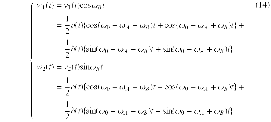
- the result is:
- v 1 (t) and v 2 (t) may be identified as:
- v 1 ( t ) 1 ⁇ 2 a ( t )cos(( ⁇ 0 ⁇ A ) t )+1 ⁇ 2 â ( t )sin(( ⁇ 0 ⁇ A ) t )
- the second mixing step is also illustrated in FIG. 17 .
- the components of the intermediate signal are added in an adder 40 , which produces the low frequency signal:
- FIG. 13 is mostly analog. By moving the A/D conversion further into the block diagram more and more digital implementations are possible.
- FIG. 19 illustrates an embodiment of the down-converter in accordance with the present invention in which two A/D converters 44 , 46 have been provided between the bandpass filter and the second mixer.
- This embodiment may utilize a complex switched capacitor bandpass filter 34 SC, for example the filter illustrated in FIG. 7 . Note that in this case the output v 1 (n), v 2 (n) from the filter is already in discrete-time form, only the actual digitalization has to be performed by the AND converters.
- mixer 36 D, 38 D will now be 30 characterized by a normalized digital frequency ⁇ B instead of the analog frequency ⁇ B .
- the complex bandpass filter may be digital, for example a BDLF filter 34 D.
- elements to the right of A/D converters 44 , 46 are digital.
- an A/D converter 44 may be applied directly to the high frequency signal, as in the embodiment of FIG. 21 . Depending on the application this may, however, require an A/D converter capable of handling very high frequency signals.
- elements to the right of A/D converter 44 are digital.
- both mixers are digital, and are characterized by normalized digital frequencies ⁇ A and ⁇ B , respectively.
- a complex bandpass filter may also be used to implement an up-converter (in accordance with the well known transposition theorem). Different embodiments of such an up-converter will now be described with reference to FIGS. 22-27.
- a digital signal a D (n) is converted into an analog signal a(t) in a D/A converter 50 (D/A converters are assumed to include appropriate anti-imaging filters).
- a first mixer 30 , 32 (in the following description first mixers in FIGS. 22-27 are assumed to include necessary lowpass filters) characterized by the frequency ⁇ A mixes the analog signal to a composite signal having an in-phase component and a quadrature component.
- a complex bandpass filter 34 filters this signal into a bandwidth limited signal. Depending on the location of the bandpass filter the upper or lower sideband will be selected.
- a second mixer 36 , 38 characterized by the frequency ⁇ B mixes this bandwidth limited signal into an intermediate signal having in-phase and quadrature components.
- an adder 40 forms the sum between the components of this intermediate signal.
- an optional multiplier 42 may be provided to account for the factor 1 ⁇ 2 introduced by the two mixers (instead of only one mixer in the prior art illustrated in FIG. 8 ).
- the up-converter may, as the down-converter, be more or less digital, depending on the location of the D/A conversion step.
- D/A converters 50 , 52 have been provided between the first mixer and the complex bandpass filter.
- mixer 30 D, 32 D will be digital.
- the D/A conversion has been moved behind the complex filter, which is now a digital filter 34 D, for example a complex digital BDLF bandpass filter.
- a digital filter 34 D for example a complex digital BDLF bandpass filter.
- the second mixer and the adder may be analog (FIG. 24) or digital (FIG. 25 ). It is also possible to perform the D/A conversion immediately before an analog addition.
- the up-converter may also be implemented with a complex switched capacitor bandpass filter 34 SC as illustrated in FIGS. 26 and 27. Since a switched capacitor filter requires an analog input signal D/A converters 54 , 56 are provided in front of the filter (naturally the D/A conversion may be performed earlier, as in the embodiment of FIG. 22 ). Furthermore, since the output signal of a switched capacitor filter is a discrete-time signal, a further D/A conversion is performed, either directly after the filter (FIG. 26) or after the second mixer (FIG. 27 ).
- the components of the intermediate signal are added. This requires that the mixers have different phase relations (“ ⁇ sin” and “sin”). If the mixers have the same phase relation, the components may be subtracted from each other instead to compensate for this.
- FIG. 28 is a flow chart illustrating the down-conversion method in accordance with the present invention.
- the process starts in step 100 .
- the high frequency signal is mixed into a composite signal having an in-phase component and a quadrature component.
- the composite signal is bandwidth limited, in a complex bandpass filter, into a bandwidth limited signal having an in-phase component and a quadrature component.
- the bandwidth limited signal is mixed into an intermediate signal having an in-phase component and a quadrature component.
- one component of the intermediate signal is added (subtracted) to (from) the other component. This ends the process in step 110 .
- FIG. 29 is a flow chart illustrating the up-conversion method in accordance with the present invention.
- the process starts in step 200 .
- the low frequency signal is mixed into a composite signal having an in-phase component and a quadrature component.
- the composite signal is bandwidth limited, in a complex bandpass filter, into a bandwidth limited signal having an in-phase component and a quadrature component.
- the bandwidth limited signal is mixed into an intermediate signal having an in-phase component and a quadrature component.
- one component of the intermediate signal is added (subtracted) to (from ) to) the other component. This ends the process in step 210 .
- an essential part of the present invention is the reconstruction (generation) of a low (high) frequency signal from a composite signal having an in-phase component and a quadrature component.
- the invention uses a complex bandpass filter and a mixer. Since this part of the invention has already been described in detail with reference to and is embedded in the down- and up-converters, a further description is not necessary.
- the present invention has been described with reference to single sideband amplitude modulation.
- complex bandpass filters may also be used in other types of amplitude modulation, such as double sideband modulation, to eliminate Hilbert filters.
- the present invention may be applied to modulation in general (amplitude, frequency, phase), both digital and analog, and to deterministic as well as stochastic signals.
Abstract
Description


Claims (10)
Applications Claiming Priority (2)
| Application Number | Priority Date | Filing Date | Title |
|---|---|---|---|
| SE9703617 | 1997-10-03 | ||
| SE9703617A SE514795C2 (en) | 1997-10-03 | 1997-10-03 | Device and method for up and down conversion |
Publications (1)
| Publication Number | Publication Date |
|---|---|
| US6611569B1 true US6611569B1 (en) | 2003-08-26 |
Family
ID=20408503
Family Applications (1)
| Application Number | Title | Priority Date | Filing Date |
|---|---|---|---|
| US09/165,644 Expired - Lifetime US6611569B1 (en) | 1997-10-03 | 1998-10-02 | Down/up-conversion apparatus and method |
Country Status (10)
| Country | Link |
|---|---|
| US (1) | US6611569B1 (en) |
| EP (1) | EP1057253B1 (en) |
| JP (1) | JP2001519611A (en) |
| CN (1) | CN1171379C (en) |
| AU (1) | AU9370298A (en) |
| BR (1) | BR9812708A (en) |
| CA (1) | CA2305134C (en) |
| DE (1) | DE69838230T2 (en) |
| SE (1) | SE514795C2 (en) |
| WO (1) | WO1999018657A2 (en) |
Cited By (26)
| Publication number | Priority date | Publication date | Assignee | Title |
|---|---|---|---|---|
| WO2004028000A2 (en) * | 2002-09-20 | 2004-04-01 | Ditrans Corporation | Complex-if digital receiver |
| US6798351B1 (en) * | 1998-10-21 | 2004-09-28 | Parkervision, Inc. | Automated meter reader applications of universal frequency translation |
| US6813485B2 (en) | 1998-10-21 | 2004-11-02 | Parkervision, Inc. | Method and system for down-converting and up-converting an electromagnetic signal, and transforms for same |
| US6836650B2 (en) | 1998-10-21 | 2004-12-28 | Parkervision, Inc. | Methods and systems for down-converting electromagnetic signals, and applications thereof |
| US20050251369A1 (en) * | 2004-05-07 | 2005-11-10 | Decarlo Robert D | Decoding an alternator output signal |
| US20060145900A1 (en) * | 2002-05-22 | 2006-07-06 | Patrick Clement | Analog-to-digital converter arrangement and method |
| US20080304549A1 (en) * | 2007-06-05 | 2008-12-11 | Calico Steve E | Hybrid band directed energy target disruption |
| US7486338B1 (en) * | 2003-04-28 | 2009-02-03 | Wyszynski Adam S | Fully integrated terrestrial TV tuner architecture |
| US20090174822A1 (en) * | 2006-06-16 | 2009-07-09 | Michael Anthony Pugel | Multichannel Digital Cable Tuner |
| US7653145B2 (en) | 1999-08-04 | 2010-01-26 | Parkervision, Inc. | Wireless local area network (WLAN) using universal frequency translation technology including multi-phase embodiments and circuit implementations |
| US7653158B2 (en) | 2001-11-09 | 2010-01-26 | Parkervision, Inc. | Gain control in a communication channel |
| US7693230B2 (en) | 1999-04-16 | 2010-04-06 | Parkervision, Inc. | Apparatus and method of differential IQ frequency up-conversion |
| US7724845B2 (en) | 1999-04-16 | 2010-05-25 | Parkervision, Inc. | Method and system for down-converting and electromagnetic signal, and transforms for same |
| US7773688B2 (en) | 1999-04-16 | 2010-08-10 | Parkervision, Inc. | Method, system, and apparatus for balanced frequency up-conversion, including circuitry to directly couple the outputs of multiple transistors |
| US7822401B2 (en) | 2000-04-14 | 2010-10-26 | Parkervision, Inc. | Apparatus and method for down-converting electromagnetic signals by controlled charging and discharging of a capacitor |
| US7865177B2 (en) | 1998-10-21 | 2011-01-04 | Parkervision, Inc. | Method and system for down-converting an electromagnetic signal, and transforms for same, and aperture relationships |
| US7894789B2 (en) | 1999-04-16 | 2011-02-22 | Parkervision, Inc. | Down-conversion of an electromagnetic signal with feedback control |
| US7991815B2 (en) | 2000-11-14 | 2011-08-02 | Parkervision, Inc. | Methods, systems, and computer program products for parallel correlation and applications thereof |
| US8019291B2 (en) | 1998-10-21 | 2011-09-13 | Parkervision, Inc. | Method and system for frequency down-conversion and frequency up-conversion |
| US8160196B2 (en) | 2002-07-18 | 2012-04-17 | Parkervision, Inc. | Networking methods and systems |
| US8233855B2 (en) | 1998-10-21 | 2012-07-31 | Parkervision, Inc. | Up-conversion based on gated information signal |
| US20120206285A1 (en) * | 2010-08-13 | 2012-08-16 | Rf Micro Devices, Inc. | Half-bandwidth based quadrature analog-to-digital converter |
| US8295406B1 (en) | 1999-08-04 | 2012-10-23 | Parkervision, Inc. | Universal platform module for a plurality of communication protocols |
| US8407061B2 (en) | 2002-07-18 | 2013-03-26 | Parkervision, Inc. | Networking methods and systems |
| US11303326B2 (en) * | 2018-03-08 | 2022-04-12 | Telefonaktiebolaget Lm Ericsson (Publ) | Method and apparatus for handling antenna signals for transmission between a base unit and a remote unit of a base station system |
| US11463071B2 (en) | 2018-04-23 | 2022-10-04 | Samsung Electronics Co,. Ltd | Asymmetrical filtering to improve GNSS performance in presence of wideband interference |
Families Citing this family (8)
| Publication number | Priority date | Publication date | Assignee | Title |
|---|---|---|---|---|
| CA2281236C (en) | 1999-09-01 | 2010-02-09 | Tajinder Manku | Direct conversion rf schemes using a virtually generated local oscillator |
| JP2002076975A (en) * | 2000-08-17 | 2002-03-15 | Samsung Electronics Co Ltd | Digital down converter and receiver |
| CN100369377C (en) * | 2003-04-16 | 2008-02-13 | 鼎芯半导体〔上海〕有限公司 | Low-converter mixer with low noise high linear |
| EP1820277B1 (en) * | 2004-12-10 | 2010-02-03 | Maxlinear, Inc. | Harmonic reject receiver architecture and mixer |
| US7383728B2 (en) | 2005-07-13 | 2008-06-10 | Ultimate Balance, Inc. | Orientation and motion sensing in athletic training systems, physical rehabilitation and evaluation systems, and hand-held devices |
| US20090102546A1 (en) * | 2006-03-17 | 2009-04-23 | Hiroshi Miyagi | Composite band-pass filter and method of filtering quadrature signals |
| JP2019531676A (en) * | 2016-02-28 | 2019-10-31 | ワクスマン、シャイ | FHSS hot spot apparatus and method |
| EP4339653A1 (en) * | 2022-09-19 | 2024-03-20 | Leuze electronic GmbH + Co. KG | Optical sensor |
Citations (18)
| Publication number | Priority date | Publication date | Assignee | Title |
|---|---|---|---|---|
| US3949309A (en) * | 1971-11-09 | 1976-04-06 | The United States Of America As Represented By The Secretary Of The Navy | Non-linear processor for anti-jam operation |
| US4458216A (en) * | 1981-09-22 | 1984-07-03 | Racal-Vadic, Inc. | Switched-capacitor modulator for quadrature modulation |
| GB2176356A (en) | 1985-06-12 | 1986-12-17 | Philips Electronic Associated | Method of, and demodulator for, digitally demodulating an ssb signal |
| US4710814A (en) * | 1985-08-27 | 1987-12-01 | Deutsche Itt Industries Gmbh | Television sound receiving circuit for at least one sound channel contained in an RF signal |
| US4736390A (en) * | 1986-10-15 | 1988-04-05 | Itt Avionics, A Division Of Itt Corporation | Zero IF radio receiver apparatus |
| EP0502449A1 (en) | 1991-03-04 | 1992-09-09 | Siemens Schweiz AG | Frequency converter |
| US5473280A (en) * | 1993-02-18 | 1995-12-05 | Hitachi, Ltd. | Modulation/demodulation method and system for realizing quadrature modulation/demodulation technique used in digital mobile radio system with complex signal processing |
| US5517529A (en) | 1993-10-18 | 1996-05-14 | Westinghouse Electric Corp. | UHF/L-Band monolithic direct digital receiver |
| WO1998011672A1 (en) | 1996-09-13 | 1998-03-19 | University Of Washington | Simplified high frequency tuner and tuning method |
| US5749051A (en) * | 1996-07-18 | 1998-05-05 | Ericsson Inc. | Compensation for second order intermodulation in a homodyne receiver |
| US5786782A (en) * | 1996-01-05 | 1998-07-28 | Nokia Mobile Phones Ltd. | Multiplexed signal conversion |
| US5821782A (en) * | 1995-12-18 | 1998-10-13 | Lucent Technologies Inc. | Frequency synthesis using a remodulator |
| US5825242A (en) * | 1994-04-05 | 1998-10-20 | Cable Television Laboratories | Modulator/demodulator using baseband filtering |
| US5903609A (en) * | 1995-06-08 | 1999-05-11 | U.S. Philips Corporation | Transmission system using transmitter with phase modulator and frequency multiplier |
| US5956620A (en) * | 1997-01-17 | 1999-09-21 | Com Dev Limited | Analog processor for digital satellites |
| US6035186A (en) * | 1996-03-19 | 2000-03-07 | U.S. Philips Corporation | Integrated receiver |
| US6215828B1 (en) * | 1996-02-10 | 2001-04-10 | Telefonaktiebolaget Lm Ericsson (Publ) | Signal transformation method and apparatus |
| US6275540B1 (en) * | 1997-10-01 | 2001-08-14 | Motorola, Inc. | Selective call receiver having an apparatus for modifying an analog signal to a digital signal and method therefor |
-
1997
- 1997-10-03 SE SE9703617A patent/SE514795C2/en not_active IP Right Cessation
-
1998
- 1998-09-28 EP EP98946753A patent/EP1057253B1/en not_active Expired - Lifetime
- 1998-09-28 DE DE69838230T patent/DE69838230T2/en not_active Expired - Lifetime
- 1998-09-28 WO PCT/SE1998/001726 patent/WO1999018657A2/en active IP Right Grant
- 1998-09-28 BR BR9812708-0A patent/BR9812708A/en not_active IP Right Cessation
- 1998-09-28 CA CA002305134A patent/CA2305134C/en not_active Expired - Lifetime
- 1998-09-28 CN CNB988098520A patent/CN1171379C/en not_active Expired - Lifetime
- 1998-09-28 JP JP2000515328A patent/JP2001519611A/en active Pending
- 1998-09-28 AU AU93702/98A patent/AU9370298A/en not_active Abandoned
- 1998-10-02 US US09/165,644 patent/US6611569B1/en not_active Expired - Lifetime
Patent Citations (19)
| Publication number | Priority date | Publication date | Assignee | Title |
|---|---|---|---|---|
| US3949309A (en) * | 1971-11-09 | 1976-04-06 | The United States Of America As Represented By The Secretary Of The Navy | Non-linear processor for anti-jam operation |
| US4458216A (en) * | 1981-09-22 | 1984-07-03 | Racal-Vadic, Inc. | Switched-capacitor modulator for quadrature modulation |
| GB2176356A (en) | 1985-06-12 | 1986-12-17 | Philips Electronic Associated | Method of, and demodulator for, digitally demodulating an ssb signal |
| US4803700A (en) * | 1985-06-12 | 1989-02-07 | U.S. Philips Corp. | Method of, and demodulator for, digitally demodulating an SSB signal |
| US4710814A (en) * | 1985-08-27 | 1987-12-01 | Deutsche Itt Industries Gmbh | Television sound receiving circuit for at least one sound channel contained in an RF signal |
| US4736390A (en) * | 1986-10-15 | 1988-04-05 | Itt Avionics, A Division Of Itt Corporation | Zero IF radio receiver apparatus |
| EP0502449A1 (en) | 1991-03-04 | 1992-09-09 | Siemens Schweiz AG | Frequency converter |
| US5473280A (en) * | 1993-02-18 | 1995-12-05 | Hitachi, Ltd. | Modulation/demodulation method and system for realizing quadrature modulation/demodulation technique used in digital mobile radio system with complex signal processing |
| US5517529A (en) | 1993-10-18 | 1996-05-14 | Westinghouse Electric Corp. | UHF/L-Band monolithic direct digital receiver |
| US5825242A (en) * | 1994-04-05 | 1998-10-20 | Cable Television Laboratories | Modulator/demodulator using baseband filtering |
| US5903609A (en) * | 1995-06-08 | 1999-05-11 | U.S. Philips Corporation | Transmission system using transmitter with phase modulator and frequency multiplier |
| US5821782A (en) * | 1995-12-18 | 1998-10-13 | Lucent Technologies Inc. | Frequency synthesis using a remodulator |
| US5786782A (en) * | 1996-01-05 | 1998-07-28 | Nokia Mobile Phones Ltd. | Multiplexed signal conversion |
| US6215828B1 (en) * | 1996-02-10 | 2001-04-10 | Telefonaktiebolaget Lm Ericsson (Publ) | Signal transformation method and apparatus |
| US6035186A (en) * | 1996-03-19 | 2000-03-07 | U.S. Philips Corporation | Integrated receiver |
| US5749051A (en) * | 1996-07-18 | 1998-05-05 | Ericsson Inc. | Compensation for second order intermodulation in a homodyne receiver |
| WO1998011672A1 (en) | 1996-09-13 | 1998-03-19 | University Of Washington | Simplified high frequency tuner and tuning method |
| US5956620A (en) * | 1997-01-17 | 1999-09-21 | Com Dev Limited | Analog processor for digital satellites |
| US6275540B1 (en) * | 1997-10-01 | 2001-08-14 | Motorola, Inc. | Selective call receiver having an apparatus for modifying an analog signal to a digital signal and method therefor |
Non-Patent Citations (4)
| Title |
|---|
| Bracewell, Ronald N., "The Fourier Transform and its Applications" McGraw-Hill Book Company, pp107&267. |
| Hambley, Allan R., "An Introduction to Communication Systems", Computer Science Press, pp82&103. |
| Jantzi, S.; Martin, K.; Snelgrove, M.; Sedra, A.; "A Complex Bandpass Delta-Sigma Converter for Digital Radio", 1994 IEEE International Symposium, vol.: 5, May 30-Jun. 2, 1994; pp. 453-456 vol. 5.* * |
| Signell, Svante, et al., "Design and Analysis of Bilinear Digital Ladder Filters", IEEE Transactions on Circuits and Systems, pp1-13. |
Cited By (53)
| Publication number | Priority date | Publication date | Assignee | Title |
|---|---|---|---|---|
| US7693502B2 (en) | 1998-10-21 | 2010-04-06 | Parkervision, Inc. | Method and system for down-converting an electromagnetic signal, transforms for same, and aperture relationships |
| US8340618B2 (en) | 1998-10-21 | 2012-12-25 | Parkervision, Inc. | Method and system for down-converting an electromagnetic signal, and transforms for same, and aperture relationships |
| US6798351B1 (en) * | 1998-10-21 | 2004-09-28 | Parkervision, Inc. | Automated meter reader applications of universal frequency translation |
| US6813485B2 (en) | 1998-10-21 | 2004-11-02 | Parkervision, Inc. | Method and system for down-converting and up-converting an electromagnetic signal, and transforms for same |
| US6836650B2 (en) | 1998-10-21 | 2004-12-28 | Parkervision, Inc. | Methods and systems for down-converting electromagnetic signals, and applications thereof |
| US20050009494A1 (en) * | 1998-10-21 | 2005-01-13 | Parkervision, Inc. | Method and system for down-converting and up-converting an electromagnetic signal, and transforms for same |
| US8233855B2 (en) | 1998-10-21 | 2012-07-31 | Parkervision, Inc. | Up-conversion based on gated information signal |
| US8190108B2 (en) | 1998-10-21 | 2012-05-29 | Parkervision, Inc. | Method and system for frequency up-conversion |
| US8190116B2 (en) | 1998-10-21 | 2012-05-29 | Parker Vision, Inc. | Methods and systems for down-converting a signal using a complementary transistor structure |
| US8160534B2 (en) | 1998-10-21 | 2012-04-17 | Parkervision, Inc. | Applications of universal frequency translation |
| US8019291B2 (en) | 1998-10-21 | 2011-09-13 | Parkervision, Inc. | Method and system for frequency down-conversion and frequency up-conversion |
| US7308242B2 (en) * | 1998-10-21 | 2007-12-11 | Parkervision, Inc. | Method and system for down-converting and up-converting an electromagnetic signal, and transforms for same |
| US7937059B2 (en) | 1998-10-21 | 2011-05-03 | Parkervision, Inc. | Converting an electromagnetic signal via sub-sampling |
| US7936022B2 (en) | 1998-10-21 | 2011-05-03 | Parkervision, Inc. | Method and circuit for down-converting a signal |
| US7865177B2 (en) | 1998-10-21 | 2011-01-04 | Parkervision, Inc. | Method and system for down-converting an electromagnetic signal, and transforms for same, and aperture relationships |
| US7826817B2 (en) | 1998-10-21 | 2010-11-02 | Parker Vision, Inc. | Applications of universal frequency translation |
| US7697916B2 (en) | 1998-10-21 | 2010-04-13 | Parkervision, Inc. | Applications of universal frequency translation |
| US8223898B2 (en) | 1999-04-16 | 2012-07-17 | Parkervision, Inc. | Method and system for down-converting an electromagnetic signal, and transforms for same |
| US8036304B2 (en) | 1999-04-16 | 2011-10-11 | Parkervision, Inc. | Apparatus and method of differential IQ frequency up-conversion |
| US8594228B2 (en) | 1999-04-16 | 2013-11-26 | Parkervision, Inc. | Apparatus and method of differential IQ frequency up-conversion |
| US7724845B2 (en) | 1999-04-16 | 2010-05-25 | Parkervision, Inc. | Method and system for down-converting and electromagnetic signal, and transforms for same |
| US7773688B2 (en) | 1999-04-16 | 2010-08-10 | Parkervision, Inc. | Method, system, and apparatus for balanced frequency up-conversion, including circuitry to directly couple the outputs of multiple transistors |
| US7693230B2 (en) | 1999-04-16 | 2010-04-06 | Parkervision, Inc. | Apparatus and method of differential IQ frequency up-conversion |
| US8229023B2 (en) | 1999-04-16 | 2012-07-24 | Parkervision, Inc. | Wireless local area network (WLAN) using universal frequency translation technology including multi-phase embodiments |
| US8224281B2 (en) | 1999-04-16 | 2012-07-17 | Parkervision, Inc. | Down-conversion of an electromagnetic signal with feedback control |
| US7894789B2 (en) | 1999-04-16 | 2011-02-22 | Parkervision, Inc. | Down-conversion of an electromagnetic signal with feedback control |
| US7929638B2 (en) | 1999-04-16 | 2011-04-19 | Parkervision, Inc. | Wireless local area network (WLAN) using universal frequency translation technology including multi-phase embodiments |
| US8077797B2 (en) | 1999-04-16 | 2011-12-13 | Parkervision, Inc. | Method, system, and apparatus for balanced frequency up-conversion of a baseband signal |
| US8295406B1 (en) | 1999-08-04 | 2012-10-23 | Parkervision, Inc. | Universal platform module for a plurality of communication protocols |
| US7653145B2 (en) | 1999-08-04 | 2010-01-26 | Parkervision, Inc. | Wireless local area network (WLAN) using universal frequency translation technology including multi-phase embodiments and circuit implementations |
| US8295800B2 (en) | 2000-04-14 | 2012-10-23 | Parkervision, Inc. | Apparatus and method for down-converting electromagnetic signals by controlled charging and discharging of a capacitor |
| US7822401B2 (en) | 2000-04-14 | 2010-10-26 | Parkervision, Inc. | Apparatus and method for down-converting electromagnetic signals by controlled charging and discharging of a capacitor |
| US7991815B2 (en) | 2000-11-14 | 2011-08-02 | Parkervision, Inc. | Methods, systems, and computer program products for parallel correlation and applications thereof |
| US7653158B2 (en) | 2001-11-09 | 2010-01-26 | Parkervision, Inc. | Gain control in a communication channel |
| US8446994B2 (en) | 2001-11-09 | 2013-05-21 | Parkervision, Inc. | Gain control in a communication channel |
| US7190293B2 (en) * | 2002-05-22 | 2007-03-13 | Freescale Semiconductor, Inc. | Sigma-delta analog-to-digital converter and method for reducing harmonics |
| US20060145900A1 (en) * | 2002-05-22 | 2006-07-06 | Patrick Clement | Analog-to-digital converter arrangement and method |
| US8160196B2 (en) | 2002-07-18 | 2012-04-17 | Parkervision, Inc. | Networking methods and systems |
| US8407061B2 (en) | 2002-07-18 | 2013-03-26 | Parkervision, Inc. | Networking methods and systems |
| US7173980B2 (en) * | 2002-09-20 | 2007-02-06 | Ditrans Ip, Inc. | Complex-IF digital receiver |
| WO2004028000A2 (en) * | 2002-09-20 | 2004-04-01 | Ditrans Corporation | Complex-if digital receiver |
| WO2004028000A3 (en) * | 2002-09-20 | 2004-05-27 | Ditrans Corp | Complex-if digital receiver |
| US7486338B1 (en) * | 2003-04-28 | 2009-02-03 | Wyszynski Adam S | Fully integrated terrestrial TV tuner architecture |
| US20050251369A1 (en) * | 2004-05-07 | 2005-11-10 | Decarlo Robert D | Decoding an alternator output signal |
| US7162397B2 (en) * | 2004-05-07 | 2007-01-09 | Snap-On Incorporated | Decoding an alternator output signal |
| US20090174822A1 (en) * | 2006-06-16 | 2009-07-09 | Michael Anthony Pugel | Multichannel Digital Cable Tuner |
| US8902369B2 (en) * | 2006-06-16 | 2014-12-02 | Thomson Licensing | Multichannel digital cable tuner |
| US8600290B2 (en) * | 2007-06-05 | 2013-12-03 | Lockheed Martin Corporation | Hybrid band directed energy target disruption |
| US20080304549A1 (en) * | 2007-06-05 | 2008-12-11 | Calico Steve E | Hybrid band directed energy target disruption |
| US20120206285A1 (en) * | 2010-08-13 | 2012-08-16 | Rf Micro Devices, Inc. | Half-bandwidth based quadrature analog-to-digital converter |
| US8525717B2 (en) * | 2010-08-13 | 2013-09-03 | Rf Micro Devices, Inc. | Half-bandwidth based quadrature analog-to-digital converter |
| US11303326B2 (en) * | 2018-03-08 | 2022-04-12 | Telefonaktiebolaget Lm Ericsson (Publ) | Method and apparatus for handling antenna signals for transmission between a base unit and a remote unit of a base station system |
| US11463071B2 (en) | 2018-04-23 | 2022-10-04 | Samsung Electronics Co,. Ltd | Asymmetrical filtering to improve GNSS performance in presence of wideband interference |
Also Published As
| Publication number | Publication date |
|---|---|
| JP2001519611A (en) | 2001-10-23 |
| AU9370298A (en) | 1999-04-27 |
| SE9703617D0 (en) | 1997-10-03 |
| WO1999018657A3 (en) | 1999-06-24 |
| BR9812708A (en) | 2000-11-28 |
| EP1057253B1 (en) | 2007-08-08 |
| SE9703617L (en) | 1999-04-04 |
| DE69838230T2 (en) | 2008-05-08 |
| CN1171379C (en) | 2004-10-13 |
| CN1273707A (en) | 2000-11-15 |
| WO1999018657A2 (en) | 1999-04-15 |
| EP1057253A2 (en) | 2000-12-06 |
| CA2305134C (en) | 2005-01-25 |
| DE69838230D1 (en) | 2007-09-20 |
| SE514795C2 (en) | 2001-04-23 |
| CA2305134A1 (en) | 1999-04-15 |
Similar Documents
| Publication | Publication Date | Title |
|---|---|---|
| US6611569B1 (en) | Down/up-conversion apparatus and method | |
| KR100373299B1 (en) | Signal transformation method and apparatus | |
| US4974236A (en) | Arrangement for generating an SSB signal | |
| US5621345A (en) | In-phase and quadrature sampling circuit | |
| US5222144A (en) | Digital quadrature radio receiver with two-step processing | |
| US6546061B2 (en) | Signal transformation method and apparatus | |
| US6724832B1 (en) | Vestigial sideband generator particularly for digital television | |
| US20100124257A1 (en) | Tranceiver front end for software radio system | |
| JP2001217800A (en) | Double digital low-if compound receiver | |
| US5404405A (en) | FM stereo decoder and method using digital signal processing | |
| US7130361B1 (en) | Telecommunication device with analog fourier transformation unit | |
| JP3953164B2 (en) | Digital quadrature modulator and demodulator | |
| JP2002300224A (en) | Receiver | |
| JP3230786B2 (en) | Digitized quadrature phase modulation circuit | |
| JP3230787B2 (en) | Digitized quadrature phase modulation circuit | |
| JP3369383B2 (en) | Modulator | |
| JPH0823359A (en) | Digital quadrature modulation device | |
| JP3960692B2 (en) | Digital quadrature modulator | |
| JP2901427B2 (en) | FM demodulator | |
| WO2003069772A2 (en) | Digital modulator | |
| JP2002111772A (en) | Receiving circuit | |
| JP2001177593A (en) | Orthogonal modulation device for digital broadcast | |
| JP2001069182A (en) | Am demodulation system | |
| JP2002232499A (en) | Orthogonal modulator |
Legal Events
| Date | Code | Title | Description |
|---|---|---|---|
| AS | Assignment |
Owner name: TELEFONAKTIEBOLAGET LM ERICSSON, SWEDEN Free format text: ASSIGNMENT OF ASSIGNORS INTEREST;ASSIGNORS:SCHIER, THORSTEN;SIGNELL, SVANTE;REEL/FRAME:009665/0438 Effective date: 19981207 |
|
| STCF | Information on status: patent grant |
Free format text: PATENTED CASE |
|
| FPAY | Fee payment |
Year of fee payment: 4 |
|
| FPAY | Fee payment |
Year of fee payment: 8 |
|
| AS | Assignment |
Owner name: CLUSTER LLC, DELAWARE Free format text: ASSIGNMENT OF ASSIGNORS INTEREST;ASSIGNOR:TELEFONAKTIEBOLAGET L M ERICSSON (PUBL);REEL/FRAME:030201/0186 Effective date: 20130211 |
|
| AS | Assignment |
Owner name: UNWIRED PLANET, LLC, NEVADA Free format text: ASSIGNMENT OF ASSIGNORS INTEREST;ASSIGNOR:CLUSTER LLC;REEL/FRAME:030219/0001 Effective date: 20130213 |
|
| AS | Assignment |
Owner name: CLUSTER LLC, SWEDEN Free format text: NOTICE OF GRANT OF SECURITY INTEREST IN PATENTS;ASSIGNOR:UNWIRED PLANET, LLC;REEL/FRAME:030369/0601 Effective date: 20130213 |
|
| FPAY | Fee payment |
Year of fee payment: 12 |