US6629392B1 - Structure for manufacture of prefabricated buildings - Google Patents
Structure for manufacture of prefabricated buildings Download PDFInfo
- Publication number
- US6629392B1 US6629392B1 US09/592,001 US59200100A US6629392B1 US 6629392 B1 US6629392 B1 US 6629392B1 US 59200100 A US59200100 A US 59200100A US 6629392 B1 US6629392 B1 US 6629392B1
- Authority
- US
- United States
- Prior art keywords
- support members
- panel
- frame
- connecting member
- structure according
- Prior art date
- Legal status (The legal status is an assumption and is not a legal conclusion. Google has not performed a legal analysis and makes no representation as to the accuracy of the status listed.)
- Expired - Fee Related, expires
Links
Images


Classifications
-
- C—CHEMISTRY; METALLURGY
- C04—CEMENTS; CONCRETE; ARTIFICIAL STONE; CERAMICS; REFRACTORIES
- C04B—LIME, MAGNESIA; SLAG; CEMENTS; COMPOSITIONS THEREOF, e.g. MORTARS, CONCRETE OR LIKE BUILDING MATERIALS; ARTIFICIAL STONE; CERAMICS; REFRACTORIES; TREATMENT OF NATURAL STONE
- C04B28/00—Compositions of mortars, concrete or artificial stone, containing inorganic binders or the reaction product of an inorganic and an organic binder, e.g. polycarboxylate cements
- C04B28/02—Compositions of mortars, concrete or artificial stone, containing inorganic binders or the reaction product of an inorganic and an organic binder, e.g. polycarboxylate cements containing hydraulic cements other than calcium sulfates
-
- Y—GENERAL TAGGING OF NEW TECHNOLOGICAL DEVELOPMENTS; GENERAL TAGGING OF CROSS-SECTIONAL TECHNOLOGIES SPANNING OVER SEVERAL SECTIONS OF THE IPC; TECHNICAL SUBJECTS COVERED BY FORMER USPC CROSS-REFERENCE ART COLLECTIONS [XRACs] AND DIGESTS
- Y10—TECHNICAL SUBJECTS COVERED BY FORMER USPC
- Y10T—TECHNICAL SUBJECTS COVERED BY FORMER US CLASSIFICATION
- Y10T428/00—Stock material or miscellaneous articles
- Y10T428/249921—Web or sheet containing structurally defined element or component
- Y10T428/249924—Noninterengaged fiber-containing paper-free web or sheet which is not of specified porosity
- Y10T428/249932—Fiber embedded in a layer derived from a water-settable material [e.g., cement, gypsum, etc.]
Definitions
- the present invention relates to prefabricated structures, and more particularly, to prefabricated wall units using unique concrete formulations and stud and beam configurations for ease of manufacture.
- Existing prefabricated structures may be formed of wall units using C-channel studs such as, for example, the wall units disclosed in U.S. Pat. No. 5,524,412.
- the wall unit is formed by pouring a first layer of cementitious composition into a mold and placing a frame of C-channel steel beams or studs onto this first layer.
- a second layer of cementitious composition is poured into a mold to a depth sufficient to cover a flange portion of the C-channel to form the wall unit.
- cementitious composition should be formulated to provide a durable surface and to be compatible with a steel stud.
- Existing wall units based on C-channel steel studs generally require flex anchors for attachment because of a difference in the coefficient of expansion between steel and existing compositions.
- the present invention is embodied in a structure and unique formulation or composition for the manufacture of prefabricated buildings.
- the structure includes a panel, a frame of support members, and bonding pads.
- Each of the support members has a defined length, a center portion of a defined height and thickness, and first and second opposed sides each of a defined width.
- a cross section of the support members presents a defined shape consisting of the center portion in combination with the first and second opposed sides.
- the bonding pads bond the panel to the frame by attaching to the frame and to one or more of the first opposed sides of the support members.
- the panel and the bonding pads are prepared from a cured/hardened moldable building material.
- the moldable building material may be a cementitious material. Prior to cure, the cementitious material may comprise a composition, by weight, of about 40.3% cement, about 40.3% sand, about 2.9% glass fibers, about 4.0% acrylic polymer, about 0.4% super plasticizer and about 12.1% water.
- the cementitious material may contains reinforcing fibers such as steel, fiberglass, polymer, graphite, or Kevlar®.
- the moldable building material may be a polymer-based resin containing fiberglass.
- the support members may be of metal, fiberglass, or wood.
- the bonding pads may enclose one or more segments of the first side(s) of one or more of the support members.
- the structure may include a connecting member.
- the connecting member may be interposed between one or more of the support members and the panel at the point where the bonding pads enclose segments of the first opposed side(s) of one or more of the support members.
- the connecting member may be affixed to the one or more support members.
- the connecting member may have an extended portion having a width that is greater than the width of the first opposed sides.
- the extended portion of the connecting member may have one or more perforations for admitting the moldable building material therethrough, prior to curing or hardening of the moldable building material.
- the connecting member may be affixed to the support member by one or more fasteners and may be entirely contained within the bonding pad.
- the connecting member may extend along the length of the support member beyond the enclosed segment of the support member and may wraps around a portion of the support member.
- the defined shape of the support members defines a structure that may have a width greater than the thickness of the center portion, thereby providing an anchor point for the bonding pads.
- the cross section of the support members may appear as an I, an L, an H, a C, a J, a T, a Z, a rectangle, or a pair of opposed triangles separated by the center portion.
- the frame may be load-bearing.
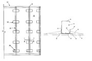
- FIG. 1 is an elevation view of a structure having a frame of lightweight support members bonded to a panel of cementitious material, according to the present invention.
- FIG. 2 is a cross-sectional plan view of a bonding pad, taken along line I—I of FIG. 1, showing the bonding pad attaching an I-shaped support member to the panel.
- FIG. 3 is a cross-sectional plan view of a bonding pad showing the bonding pad attaching an X-shaped support member to the panel.
- FIG. 4 is a cross-sectional plan view of a bonding pad showing the bonding pad attaching an inverted T-shaped support member to the panel.
- FIG. 5 is a cross-sectional plan view of a bonding pad showing the bonding pad attaching C-channel support member to the panel using a connecting member.
- FIG. 6 is a cross-sectional plan view of a bonding pad showing the bonding pad attaching C-channel support member to the panel using a flat plate connecting member.
- FIG. 7 is an elevation view of the connecting member of FIG. 5 .
- FIG. 8 is an plan view of the connecting member of FIG. 5 .
- FIG. 9 is a cross-sectional plan view of the connecting member for use with an H-shaped support member.
- FIG. 10 is a cross-sectional plan view of the connecting member for use with an L (or J)-shaped support member.
- FIG. 11 is a cross-sectional plan view of the connecting member for use with a rectangularly-shaped support member.
- FIG. 12 is a cross-sectional plan view of a bonding pad showing the bonding pad attaching the panel to a support member having triangularly-shaped ends.
- FIG. 13 is a cross-sectional plan view of a bonding pad showing the bonding pad attaching an Z-shaped support member to the panel.
- FIG. 14 is a cross-sectional plan view of two units of FIG. 1 coupled together to form a larger wall structure.
- the present invention resides in a structure and formulation for the manufacture of prefabricated buildings.
- the structure uses a uniquely formulated panel that is bonded to a frame of support members.
- the unique cementitious composition of the structure allows it to be relatively insect resistant and generally impervious to moisture.
- the structure 10 of the invention may be formed of a panel 12 bonded to a frame 14 of support members 16 by bonding pads 18 .
- the panel may be formed of a suitable moldable building material such as a cementitious composition or a polymer-based resin containing fiber glass or the like.
- An external wall panel formed of a cementitious composition generally may have a thickness between about 1 ⁇ 4 inches and about 1 inch. An advantageous thickness is about 5 ⁇ 8 inches.
- the cementitious material may be composed of a mixture of cement, polymer, plasticizer, fiberglass, water and sand.
- Table 1 indicates the preferred relative proportions, by weight prior to cure, of the ingredients for the cementitious material:
- composition limit column indicates an empirical limit based on experience with compositions used in practice.
- the range indicates compositions that should provide suitable moldable building material.
- the reinforcing fibers may be alkali resistant glass fibers and may be provided on spools and cut into lengths of about 1 ⁇ 2 inch to about 11 ⁇ 2 inches prior to mixing with the other materials. Suitable spools of fiber are available from Nippon Electric Glass America Inc. (Part No. ACS 13H530X). Alternatively, the reinforcing fibers may be formed of steel, polymer, graphite or Kevlar®.
- the acrylic polymer may be a Forton compound (VF-774) available from Ball Consulting, Ltd. of Ambridge, Pa.
- the acrylic polymer may be a Poly Plex polymer available from Nippon Electric Glass America, Inc.
- the super plasticizer may be DARACEM 19 available from W.R. Grace of Cambridge, Mass.
- the cementitious material is mixed together using an automated batch mixer.
- a typical batch size is approximately 260 pounds with the materials weighed by a computer operated batch load center in increments of ⁇ fraction (1/10) ⁇ of a pound.
- the wet materials water, polymer, and super plasticizer
- the cement and the sand are added to the wet material and mixed together for 5 minutes to form a slurry.
- the fiberglass is added and the slurry is mixed together for less than 2 minutes.
- the wet slurry has a pot life of about 1 hour.
- mixing sequence may be changed depending on batch size or mixing equipment. For example, using a tailgate mixer, it may be advantageous to mix the dry material first and then to add the wet materials.
- the mixed slurry is poured into a mold (not shown) having a depth approximately equal to the desired thickness of the panel 12 .
- Form release oil is applied to the mold before the slurry is poured into the mold.
- the slurry is tamped and evenly spread to fill the mold.
- the frame 14 of support members 16 which was preassembled, is set into place on the panel 12 while it is still in the mold and before the slurry has set.
- the frame is attached to the panel 12 by the mounting patches or pads 18 .
- the pads are formed by placing the slurry at points along the individual support members.
- the pads are tamped into place to integrate them into the panel and are shaped by hand or using a tool. Although the pad's shape may vary greatly, a cross-section of a desired pad shape is shown in FIG. 2 .
- the pad may have a width of about 5.5 inches on either side of the support member with the pad's thickness tapering away from the support member.
- the pad may have a height of about 6 inches.
- the support member has a defined length, a center portion 20 of a defined height and thickness, and first and second opposed sides, 22 and 24 .
- Each of the opposed sides has a defined width.
- a cross section of the support member presents a defined shape consisting of the center portion in combination with the first and second opposed sides.
- the defined shape of the support member is configured such that segments 26 of the first opposed sides are covered with the pad slurry with relative ease allowing for efficient manufacture of the unit.
- the bonding pads may enclose segments of the first opposed sides of the support members.
- bonding pads 18 For a structure 10 having a height (or support member length) of about 8 feet, five bonding pads 18 have been found to securely attach each support member 16 to the panel 12 .
- the bonding pads may be spaced about 21 inches apart (center-to-center), with the top and bottom pads being no more than about 6 inches from the top and bottom of the frame 14 , respectively.
- the structure may vary in height and the number of bonding pads may be increased or decreased proportionally such that the distance between the closest edges of adjacent bonding pads is not more than about 18 inches.
- a gravity strap 28 may be attached to each support member 16 and covered by a respective bonding pad 18 to prevent slippage over time of the panel 12 down along the length of the support members.
- the gravity strap may be formed of 22 gauge sheet metal having a width of about 11 ⁇ 2 inches and a length of about 5 inches.
- the gravity strap may be attached to the beam by sheet metal screws, welds, or the like.
- the structure 10 is allowed to cure in the mold for a minimum of 12 hours.
- the cure time may be reduced using a curing kiln.
- the structure is then removed from the mold by using a spreader bar, clamps and an overhead crane or forklift.
- the cured unit may be stored in a storage rack in a vertical orientation until it is ready for use.
- the support members 16 may be formed of a variety of cross-sectional shapes.
- the support member shown in FIG. 2 has an “I” cross-sectional shape.
- the I-shaped member may be a beam or a stud rolled from sheet metal or extruded.
- the support member may also be formed of fiber glass and resin, or the like.
- the I-shaped member has a center portion 20 and the first and second opposed sides, 22 and 24 .
- the bonding pads 18 cover segments 26 of the first opposed side to firmly affix the support members to the panel.
- the support members 16 shown in FIGS. 3 and 4 have an “X” cross-sectional shape and an inverted “T” cross-sectional shape, respectively.
- the X-shaped member and the T-shaped member each have a center portion 20 and first and second opposed sides, 22 and 24 .
- the support member 16 may be a “C” channel having a connecting member 40 interposed between the C-channel and the panel 12 .
- the connecting member may be welded to the C-channel or fastened by screws 42 or the like.
- the connecting member shown in FIGS. 7-8, may be rolled sheet metal that provides a recess for receiving the C-channel.
- the connecting member may be a flat plate (FIG. 6 ).
- the connecting member has extended portions 44 that extend from the support member and are covered by the bonding pad 18 .
- the connecting member 40 may have one or more holes 46 or perforations for admitting the slurry therethrough prior to curing or bonding of the moldable building material to further strengthen the attachment between the frame 14 and the panel 12 .
- the connecting members may have a length that extends only under the bonding pads 18 .
- the connecting member 40 permits the use of support members 16 having a wide variety of cross-sectional shapes.
- the support member may have an H, L, or a rectangular cross-sectional shape, respectively.
- the support members 16 may be a steel beam or stud having a lightweight double triangular shape as shown in FIG. 12 .
- the lightweight steel beam consists of a flat center portion 20 and two triangular sides 22 and 24 .
- the plate of metal that forms the beam's flat center member may have holes cut or punched in therethrough. The holes allow for a passage for pipes, electrical wires, and the like, through the wall unit.
- the support member may have a “Z” cross-sectional shape.
- the slurry for the bonding pad 18 covers and encloses the sloped edges of the first sides 22 of the support members.
- the structure of the present invention is particularly advantageous for constructing a prefabricated building.
- Several structures 10 may be coupled together to form a wall 30 as shown in FIG. 14 .
- the wall's interior surface may be covered by drywall panels 32 and patched together using drywall tape 34 and drywall compound. Any spaces between the exterior panels 12 may be filled with caulk 36 .
- the structure 10 of the invention may be used as a roof unit or a floor unit. Further, the cross-sectional height or width of the support members may be increased to accommodate an increased bearing load.
- the prefabricated building may be assembled entirely in a factory and shipped to its final destination for attachment to a foundation and utilities.
Abstract
Description
| TABLE 1 | |||||
| (% by weight - uncured) | Preferred | Range | Limit | ||
| Portland cement | 40.3% | 25-55% | ≧25% | ||
| Sand | 40.3% | 25-55% | ≦55% | ||
| Reinforcing fibers | 2.9% | 1-5% | ≦5% | ||
| Acrylic polymer | 4.0% | 1-10% | ≈1.6% | ||
| Super plasticizer | 0.4% | 0-2% | ≧0% | ||
| Water | 12.1% | 10-15% | ≈11% | ||
Claims (19)
Priority Applications (1)
| Application Number | Priority Date | Filing Date | Title |
|---|---|---|---|
| US09/592,001 US6629392B1 (en) | 1998-10-14 | 2000-06-12 | Structure for manufacture of prefabricated buildings |
Applications Claiming Priority (2)
| Application Number | Priority Date | Filing Date | Title |
|---|---|---|---|
| US09/172,741 US6073410A (en) | 1998-10-14 | 1998-10-14 | Structure and formulation for manufacture of prefabricated buildings |
| US09/592,001 US6629392B1 (en) | 1998-10-14 | 2000-06-12 | Structure for manufacture of prefabricated buildings |
Related Parent Applications (1)
| Application Number | Title | Priority Date | Filing Date |
|---|---|---|---|
| US09/172,741 Continuation-In-Part US6073410A (en) | 1998-10-14 | 1998-10-14 | Structure and formulation for manufacture of prefabricated buildings |
Publications (1)
| Publication Number | Publication Date |
|---|---|
| US6629392B1 true US6629392B1 (en) | 2003-10-07 |
Family
ID=22629017
Family Applications (2)
| Application Number | Title | Priority Date | Filing Date |
|---|---|---|---|
| US09/172,741 Expired - Fee Related US6073410A (en) | 1998-10-14 | 1998-10-14 | Structure and formulation for manufacture of prefabricated buildings |
| US09/592,001 Expired - Fee Related US6629392B1 (en) | 1998-10-14 | 2000-06-12 | Structure for manufacture of prefabricated buildings |
Family Applications Before (1)
| Application Number | Title | Priority Date | Filing Date |
|---|---|---|---|
| US09/172,741 Expired - Fee Related US6073410A (en) | 1998-10-14 | 1998-10-14 | Structure and formulation for manufacture of prefabricated buildings |
Country Status (3)
| Country | Link |
|---|---|
| US (2) | US6073410A (en) |
| AU (1) | AU6252999A (en) |
| WO (1) | WO2000022255A1 (en) |
Cited By (21)
| Publication number | Priority date | Publication date | Assignee | Title |
|---|---|---|---|---|
| WO2006047644A3 (en) * | 2004-10-25 | 2006-08-03 | Composite Support & Solutions | Fire-protection walls of cementitious composite materials |
| US20060179760A1 (en) * | 2005-02-17 | 2006-08-17 | Burg John P | Acoustic wall using compressed fiber panels |
| US20080137372A1 (en) * | 2003-10-11 | 2008-06-12 | Seung-Chul Jeong | Backlight assembly and display apparatus having the same |
| US20080168728A1 (en) * | 2007-01-17 | 2008-07-17 | Edward Scherrer | Wall system |
| US20080209833A1 (en) * | 2007-03-01 | 2008-09-04 | Ulrich Conradi | Facing system for building constructions with two-dimensionally and/or spherically shaped regions to be faced |
| US7875231B1 (en) * | 2007-02-26 | 2011-01-25 | Bracegirdle Paul E | Method for producing fiber reinforced cement-based structural building materials |
| US8635824B2 (en) | 2007-01-17 | 2014-01-28 | Edward G. Scherrer | Insulation panel system |
| US9624664B2 (en) | 2014-01-16 | 2017-04-18 | Jennifer Judd | Popcorn ceiling patch |
| US9790686B1 (en) | 2016-08-10 | 2017-10-17 | United States Gypsum Company | Triangular stud shaft wall system |
| USD863599S1 (en) | 2017-03-10 | 2019-10-15 | Edward G Scherrer | Insulation panel |
| US10653904B2 (en) | 2017-12-02 | 2020-05-19 | M-Fire Holdings, Llc | Methods of suppressing wild fires raging across regions of land in the direction of prevailing winds by forming anti-fire (AF) chemical fire-breaking systems using environmentally clean anti-fire (AF) liquid spray applied using GPS-tracking techniques |
| US10773882B2 (en) | 2017-03-10 | 2020-09-15 | Scherrer Edward G | Shipping container insulation panel and installation method |
| US10814150B2 (en) | 2017-12-02 | 2020-10-27 | M-Fire Holdings Llc | Methods of and system networks for wireless management of GPS-tracked spraying systems deployed to spray property and ground surfaces with environmentally-clean wildfire inhibitor to protect and defend against wildfires |
| US10858820B2 (en) * | 2017-05-01 | 2020-12-08 | Ram Navon | Reinforced beam system |
| US10899038B2 (en) | 2017-12-02 | 2021-01-26 | M-Fire Holdings, Llc | Class-A fire-protected wood products inhibiting ignition and spread of fire along class-A fire-protected wood surfaces and development of smoke from such fire |
| US11395931B2 (en) | 2017-12-02 | 2022-07-26 | Mighty Fire Breaker Llc | Method of and system network for managing the application of fire and smoke inhibiting compositions on ground surfaces before the incidence of wild-fires, and also thereafter, upon smoldering ambers and ashes to reduce smoke and suppress fire re-ignition |
| US11826592B2 (en) | 2018-01-09 | 2023-11-28 | Mighty Fire Breaker Llc | Process of forming strategic chemical-type wildfire breaks on ground surfaces to proactively prevent fire ignition and flame spread, and reduce the production of smoke in the presence of a wild fire |
| US11836807B2 (en) | 2017-12-02 | 2023-12-05 | Mighty Fire Breaker Llc | System, network and methods for estimating and recording quantities of carbon securely stored in class-A fire-protected wood-framed and mass-timber buildings on construction job-sites, and class-A fire-protected wood-framed and mass timber components in factory environments |
| US11865394B2 (en) | 2017-12-03 | 2024-01-09 | Mighty Fire Breaker Llc | Environmentally-clean biodegradable water-based concentrates for producing fire inhibiting and fire extinguishing liquids for fighting class A and class B fires |
| US11865390B2 (en) | 2017-12-03 | 2024-01-09 | Mighty Fire Breaker Llc | Environmentally-clean water-based fire inhibiting biochemical compositions, and methods of and apparatus for applying the same to protect property against wildfire |
| US11911643B2 (en) | 2021-02-04 | 2024-02-27 | Mighty Fire Breaker Llc | Environmentally-clean fire inhibiting and extinguishing compositions and products for sorbing flammable liquids while inhibiting ignition and extinguishing fire |
Families Citing this family (23)
| Publication number | Priority date | Publication date | Assignee | Title |
|---|---|---|---|---|
| US6073410A (en) * | 1998-10-14 | 2000-06-13 | Eco Buliding Systems, Inc. | Structure and formulation for manufacture of prefabricated buildings |
| US7849648B2 (en) * | 2004-12-30 | 2010-12-14 | United States Gypsum Company | Non-combustible reinforced cementitious lightweight panels and metal frame system for flooring |
| US7849650B2 (en) * | 2005-01-27 | 2010-12-14 | United States Gypsum Company | Non-combustible reinforced cementitious lightweight panels and metal frame system for a fire wall and other fire resistive assemblies |
| US7841148B2 (en) * | 2005-01-27 | 2010-11-30 | United States Gypsum Company | Non-combustible reinforced cementitious lightweight panels and metal frame system for roofing |
| US7849649B2 (en) | 2005-01-27 | 2010-12-14 | United States Gypsum Company | Non-combustible reinforced cementitious lightweight panels and metal frame system for shear walls |
| US7845130B2 (en) * | 2005-12-29 | 2010-12-07 | United States Gypsum Company | Reinforced cementitious shear panels |
| US7870698B2 (en) | 2006-06-27 | 2011-01-18 | United States Gypsum Company | Non-combustible reinforced cementitious lightweight panels and metal frame system for building foundations |
| US7797901B2 (en) * | 2007-01-11 | 2010-09-21 | Quality Edge, Inc. | Demountable wall system and method |
| US8312678B1 (en) * | 2009-07-23 | 2012-11-20 | Haddock Robert M M | Roof framing structure using triangular structural framing |
| US10054336B2 (en) | 2010-03-03 | 2018-08-21 | Robert M. M. Haddock | Photovoltaic module mounting assembly |
| US9611652B2 (en) | 2011-02-25 | 2017-04-04 | Dustin M. M. Haddock | Mounting device for building surfaces having elongated mounting slot |
| WO2013101597A1 (en) | 2011-12-29 | 2013-07-04 | Haddock Dustin M M | Mounting device for nail strip panels |
| WO2018023016A1 (en) | 2016-07-29 | 2018-02-01 | Haddock Dustin M M | Trapezoidal rib mounting bracket with flexible legs |
| US10640980B2 (en) | 2016-10-31 | 2020-05-05 | Rmh Tech Llc | Metal panel electrical bonding clip |
| NZ764108A (en) | 2017-10-09 | 2022-08-26 | Rmh Tech Llc | Rail assembly attachable to a building surface |
| US10311444B1 (en) | 2017-12-02 | 2019-06-04 | M-Fire Suppression, Inc. | Method of providing class-A fire-protection to wood-framed buildings using on-site spraying of clean fire inhibiting chemical liquid on exposed interior wood surfaces of the wood-framed buildings, and mobile computing systems for uploading fire-protection certifications and status information to a central database and remote access thereof by firefighters on job site locations during fire outbreaks on construction sites |
| US10430757B2 (en) | 2017-12-02 | 2019-10-01 | N-Fire Suppression, Inc. | Mass timber building factory system for producing prefabricated class-A fire-protected mass timber building components for use in constructing prefabricated class-A fire-protected mass timber buildings |
| US10290004B1 (en) | 2017-12-02 | 2019-05-14 | M-Fire Suppression, Inc. | Supply chain management system for supplying clean fire inhibiting chemical (CFIC) totes to a network of wood-treating lumber and prefabrication panel factories and wood-framed building construction job sites |
| US10332222B1 (en) | 2017-12-02 | 2019-06-25 | M-Fire Supression, Inc. | Just-in-time factory methods, system and network for prefabricating class-A fire-protected wood-framed buildings and components used to construct the same |
| CA3094498C (en) | 2018-03-21 | 2023-04-25 | Rmh Tech Llc | Pv module mounting assembly with clamp/standoff arrangement |
| EP3894760A4 (en) | 2018-12-14 | 2022-09-07 | RMH Tech LLC | Mounting device for nail strip panels |
| WO2021188442A1 (en) | 2020-03-16 | 2021-09-23 | Rmh Tech Llc | Mounting device for a metal roof |
| US11041310B1 (en) | 2020-03-17 | 2021-06-22 | Rmh Tech Llc | Mounting device for controlling uplift of a metal roof |
Citations (25)
| Publication number | Priority date | Publication date | Assignee | Title |
|---|---|---|---|---|
| FR318021A (en) | 1902-01-23 | 1902-10-03 | Bessiere | Soundproof floors in agglomerated cork |
| US1241187A (en) | 1917-02-19 | 1917-09-25 | Joseph Berliat | Mixed reinforced concrete construction without coffering. |
| US1778315A (en) | 1928-10-02 | 1930-10-14 | Thomas B Sturges | Building unit and supporting means therefor |
| US1902565A (en) | 1928-05-14 | 1933-03-21 | United States Gypsum Co | Slab floor or roof construction |
| US1959119A (en) | 1931-04-25 | 1934-05-15 | Leonie S Young | Floor construction |
| US2029009A (en) | 1934-04-23 | 1936-01-28 | United States Gypsum Co | Building construction |
| US2141919A (en) | 1937-07-31 | 1938-12-27 | Kotrbaty Guy Felix | Building construction |
| US2853394A (en) | 1953-03-30 | 1958-09-23 | United States Gypsum Co | Cementitious composition |
| US3214875A (en) | 1962-02-12 | 1965-11-02 | Nat Gypsum Co | Wall supporting and fastening means |
| US3965633A (en) | 1974-04-04 | 1976-06-29 | Decks, Incorporated | Insulated roofing structure and method |
| US4241553A (en) | 1979-02-05 | 1980-12-30 | United States Gypsum Company | Mobile home ceiling construction and method for making |
| US4441292A (en) * | 1979-02-27 | 1984-04-10 | Profoment Utvecklings Ab | Floor |
| US4748781A (en) * | 1986-10-22 | 1988-06-07 | Foamseal, Inc. | Method of bonding structural support channels to a panel and structural building module formed |
| US4793861A (en) | 1986-07-10 | 1988-12-27 | Vetrotex Saint-Gobain | Glass reinforced compositions |
| US5225237A (en) | 1988-10-14 | 1993-07-06 | Fibronit S.R.L. | Building sheets of cement material reinforced with plastics mesh and glass fibers |
| US5279091A (en) | 1992-06-26 | 1994-01-18 | Williams Mark F | Building enclosure assemblies |
| US5353563A (en) * | 1992-06-08 | 1994-10-11 | Jack White | Plastic structurally reinforced panel |
| US5499480A (en) | 1993-03-31 | 1996-03-19 | Bass; Kenneth R. | Lightweight metal truss and frame system |
| US5524412A (en) | 1993-07-23 | 1996-06-11 | Eco Building Systems, Inc. | Method and composition for constructing modular buildings |
| US5644880A (en) | 1984-02-27 | 1997-07-08 | Georgia-Pacific Corporation | Gypsum board and systems containing same |
| US5664388A (en) | 1993-03-31 | 1997-09-09 | Donna Bass | Structural shear resisting member and method employed therein |
| US5692353A (en) | 1993-03-31 | 1997-12-02 | Bass, Deceased; Kenneth R. | Lumber-compatible lightweight metal construction system |
| US5729945A (en) | 1995-04-17 | 1998-03-24 | National Gypsum Company | Wall structure and method of securing framing members to wallboards with an adhesive |
| US5758463A (en) * | 1993-03-12 | 1998-06-02 | P & M Manufacturing Co., Ltd. | Composite modular building panel |
| US6073410A (en) * | 1998-10-14 | 2000-06-13 | Eco Buliding Systems, Inc. | Structure and formulation for manufacture of prefabricated buildings |
-
1998
- 1998-10-14 US US09/172,741 patent/US6073410A/en not_active Expired - Fee Related
-
1999
- 1999-09-15 AU AU62529/99A patent/AU6252999A/en not_active Abandoned
- 1999-09-15 WO PCT/US1999/021488 patent/WO2000022255A1/en active Application Filing
-
2000
- 2000-06-12 US US09/592,001 patent/US6629392B1/en not_active Expired - Fee Related
Patent Citations (25)
| Publication number | Priority date | Publication date | Assignee | Title |
|---|---|---|---|---|
| FR318021A (en) | 1902-01-23 | 1902-10-03 | Bessiere | Soundproof floors in agglomerated cork |
| US1241187A (en) | 1917-02-19 | 1917-09-25 | Joseph Berliat | Mixed reinforced concrete construction without coffering. |
| US1902565A (en) | 1928-05-14 | 1933-03-21 | United States Gypsum Co | Slab floor or roof construction |
| US1778315A (en) | 1928-10-02 | 1930-10-14 | Thomas B Sturges | Building unit and supporting means therefor |
| US1959119A (en) | 1931-04-25 | 1934-05-15 | Leonie S Young | Floor construction |
| US2029009A (en) | 1934-04-23 | 1936-01-28 | United States Gypsum Co | Building construction |
| US2141919A (en) | 1937-07-31 | 1938-12-27 | Kotrbaty Guy Felix | Building construction |
| US2853394A (en) | 1953-03-30 | 1958-09-23 | United States Gypsum Co | Cementitious composition |
| US3214875A (en) | 1962-02-12 | 1965-11-02 | Nat Gypsum Co | Wall supporting and fastening means |
| US3965633A (en) | 1974-04-04 | 1976-06-29 | Decks, Incorporated | Insulated roofing structure and method |
| US4241553A (en) | 1979-02-05 | 1980-12-30 | United States Gypsum Company | Mobile home ceiling construction and method for making |
| US4441292A (en) * | 1979-02-27 | 1984-04-10 | Profoment Utvecklings Ab | Floor |
| US5644880A (en) | 1984-02-27 | 1997-07-08 | Georgia-Pacific Corporation | Gypsum board and systems containing same |
| US4793861A (en) | 1986-07-10 | 1988-12-27 | Vetrotex Saint-Gobain | Glass reinforced compositions |
| US4748781A (en) * | 1986-10-22 | 1988-06-07 | Foamseal, Inc. | Method of bonding structural support channels to a panel and structural building module formed |
| US5225237A (en) | 1988-10-14 | 1993-07-06 | Fibronit S.R.L. | Building sheets of cement material reinforced with plastics mesh and glass fibers |
| US5353563A (en) * | 1992-06-08 | 1994-10-11 | Jack White | Plastic structurally reinforced panel |
| US5279091A (en) | 1992-06-26 | 1994-01-18 | Williams Mark F | Building enclosure assemblies |
| US5758463A (en) * | 1993-03-12 | 1998-06-02 | P & M Manufacturing Co., Ltd. | Composite modular building panel |
| US5499480A (en) | 1993-03-31 | 1996-03-19 | Bass; Kenneth R. | Lightweight metal truss and frame system |
| US5664388A (en) | 1993-03-31 | 1997-09-09 | Donna Bass | Structural shear resisting member and method employed therein |
| US5692353A (en) | 1993-03-31 | 1997-12-02 | Bass, Deceased; Kenneth R. | Lumber-compatible lightweight metal construction system |
| US5524412A (en) | 1993-07-23 | 1996-06-11 | Eco Building Systems, Inc. | Method and composition for constructing modular buildings |
| US5729945A (en) | 1995-04-17 | 1998-03-24 | National Gypsum Company | Wall structure and method of securing framing members to wallboards with an adhesive |
| US6073410A (en) * | 1998-10-14 | 2000-06-13 | Eco Buliding Systems, Inc. | Structure and formulation for manufacture of prefabricated buildings |
Cited By (36)
| Publication number | Priority date | Publication date | Assignee | Title |
|---|---|---|---|---|
| US20080137372A1 (en) * | 2003-10-11 | 2008-06-12 | Seung-Chul Jeong | Backlight assembly and display apparatus having the same |
| US7658042B2 (en) | 2004-10-25 | 2010-02-09 | Composite Support & Solutions, Inc. | Fire-protection walls of cementitious composite materials |
| US20080134628A1 (en) * | 2004-10-25 | 2008-06-12 | Clement Hiel | Fire-Protection Walls of Cementitious Composite Materials |
| WO2006047644A3 (en) * | 2004-10-25 | 2006-08-03 | Composite Support & Solutions | Fire-protection walls of cementitious composite materials |
| US20060179760A1 (en) * | 2005-02-17 | 2006-08-17 | Burg John P | Acoustic wall using compressed fiber panels |
| US20080168728A1 (en) * | 2007-01-17 | 2008-07-17 | Edward Scherrer | Wall system |
| US8635824B2 (en) | 2007-01-17 | 2014-01-28 | Edward G. Scherrer | Insulation panel system |
| US7875231B1 (en) * | 2007-02-26 | 2011-01-25 | Bracegirdle Paul E | Method for producing fiber reinforced cement-based structural building materials |
| US20080209833A1 (en) * | 2007-03-01 | 2008-09-04 | Ulrich Conradi | Facing system for building constructions with two-dimensionally and/or spherically shaped regions to be faced |
| US9624664B2 (en) | 2014-01-16 | 2017-04-18 | Jennifer Judd | Popcorn ceiling patch |
| US9790686B1 (en) | 2016-08-10 | 2017-10-17 | United States Gypsum Company | Triangular stud shaft wall system |
| USD863599S1 (en) | 2017-03-10 | 2019-10-15 | Edward G Scherrer | Insulation panel |
| US10773882B2 (en) | 2017-03-10 | 2020-09-15 | Scherrer Edward G | Shipping container insulation panel and installation method |
| US10858820B2 (en) * | 2017-05-01 | 2020-12-08 | Ram Navon | Reinforced beam system |
| US11395931B2 (en) | 2017-12-02 | 2022-07-26 | Mighty Fire Breaker Llc | Method of and system network for managing the application of fire and smoke inhibiting compositions on ground surfaces before the incidence of wild-fires, and also thereafter, upon smoldering ambers and ashes to reduce smoke and suppress fire re-ignition |
| US11697041B2 (en) | 2017-12-02 | 2023-07-11 | Mighty Fire Breaker Llc | Method of proactively defending combustible property against fire ignition and flame spread in the presence of wild fire |
| US10899038B2 (en) | 2017-12-02 | 2021-01-26 | M-Fire Holdings, Llc | Class-A fire-protected wood products inhibiting ignition and spread of fire along class-A fire-protected wood surfaces and development of smoke from such fire |
| US10919178B2 (en) | 2017-12-02 | 2021-02-16 | M-Fire Holdings, Llc | Class-A fire-protected oriented strand board (OSB) sheathing, and method of and automated factory for producing the same |
| US10653904B2 (en) | 2017-12-02 | 2020-05-19 | M-Fire Holdings, Llc | Methods of suppressing wild fires raging across regions of land in the direction of prevailing winds by forming anti-fire (AF) chemical fire-breaking systems using environmentally clean anti-fire (AF) liquid spray applied using GPS-tracking techniques |
| US11400324B2 (en) | 2017-12-02 | 2022-08-02 | Mighty Fire Breaker Llc | Method of protecting life, property, homes and businesses from wild fire by proactively applying environmentally-clean anti-fire (AF) chemical liquid spray in advance of wild fire arrival and managed using a wireless network with GPS-tracking |
| US11633636B2 (en) | 2017-12-02 | 2023-04-25 | Mighty Fire Breaker Llc | Wireless neighborhood wildfire defense system network supporting proactive protection of life and property in a neighborhood through GPS-tracking and mapping of environmentally-clean anti-fire (AF) chemical liquid spray applied to the property before wild fires reach the neighborhood |
| US11638844B2 (en) | 2017-12-02 | 2023-05-02 | Mighty Fire Breaker Llc | Method of proactively protecting property from wild fire by spraying environmentally-clean anti-fire chemical liquid on property surfaces prior to wild fire arrival using remote sensing and GPS-tracking and mapping enabled spraying |
| US11642555B2 (en) | 2017-12-02 | 2023-05-09 | Mighty Fire Breaker Llc | Wireless wildfire defense system network for proactively defending homes and neighborhoods against wild fires by spraying environmentally-clean anti-fire chemical liquid on property and buildings and forming GPS-tracked and mapped chemical fire breaks about the property |
| US11654314B2 (en) | 2017-12-02 | 2023-05-23 | Mighty Fire Breaker Llc | Method of managing the proactive spraying of environment ally-clean anti-fire chemical liquid on GPS-specified property surfaces so as to inhibit fire ignition and flame spread in the presence of wild fire |
| US11654313B2 (en) | 2017-12-02 | 2023-05-23 | Mighty Fire Breaker Llc | Wireless communication network, GPS-tracked ground-based spraying tanker vehicles and command center configured for proactively spraying environmentally-safe anti-fire chemical liquid on property surfaces to inhibit fire ignition and flame spread in the presence of wild fire |
| US10814150B2 (en) | 2017-12-02 | 2020-10-27 | M-Fire Holdings Llc | Methods of and system networks for wireless management of GPS-tracked spraying systems deployed to spray property and ground surfaces with environmentally-clean wildfire inhibitor to protect and defend against wildfires |
| US11697039B2 (en) | 2017-12-02 | 2023-07-11 | Mighty Fire Breaker Llc | Wireless communication network, GPS-tracked back-pack spraying systems and command center configured for proactively spraying environmentally-safe anti-fire chemical liquid on property surfaces to inhibit fire ignition and flame spread in the presence of wild fire |
| US11697040B2 (en) | 2017-12-02 | 2023-07-11 | Mighty Fire Breaker Llc | Wild fire defense system network using a command center, spraying systems and mobile computing systems configured to proactively defend homes and neighborhoods against threat of wild fire by spraying environmentally-safe anti-fire chemical liquid on property surfaces before presence of wild fire |
| US11707639B2 (en) | 2017-12-02 | 2023-07-25 | Mighty Fire Breaker Llc | Wireless communication network, GPS-tracked mobile spraying systems, and a command system configured for proactively spraying environmentally-safe anti-fire chemical liquid on combustible property surfaces to protect property against fire ignition and flame spread in the presence of wild fire |
| US11730987B2 (en) | 2017-12-02 | 2023-08-22 | Mighty Fire Breaker Llc | GPS tracking and mapping wildfire defense system network for proactively defending homes and neighborhoods against threat of wild fire by spraying environmentally-safe anti-fire chemical liquid on property surfaces to inhibit fire ignition and flame spread in the presence of wild fire |
| US11794044B2 (en) | 2017-12-02 | 2023-10-24 | Mighty Fire Breaker Llc | Method of proactively forming and maintaining GPS-tracked and mapped environmentally-clean chemical firebreaks and fire protection zones that inhibit fire ignition and flame spread in the presence of wild fire |
| US11836807B2 (en) | 2017-12-02 | 2023-12-05 | Mighty Fire Breaker Llc | System, network and methods for estimating and recording quantities of carbon securely stored in class-A fire-protected wood-framed and mass-timber buildings on construction job-sites, and class-A fire-protected wood-framed and mass timber components in factory environments |
| US11865394B2 (en) | 2017-12-03 | 2024-01-09 | Mighty Fire Breaker Llc | Environmentally-clean biodegradable water-based concentrates for producing fire inhibiting and fire extinguishing liquids for fighting class A and class B fires |
| US11865390B2 (en) | 2017-12-03 | 2024-01-09 | Mighty Fire Breaker Llc | Environmentally-clean water-based fire inhibiting biochemical compositions, and methods of and apparatus for applying the same to protect property against wildfire |
| US11826592B2 (en) | 2018-01-09 | 2023-11-28 | Mighty Fire Breaker Llc | Process of forming strategic chemical-type wildfire breaks on ground surfaces to proactively prevent fire ignition and flame spread, and reduce the production of smoke in the presence of a wild fire |
| US11911643B2 (en) | 2021-02-04 | 2024-02-27 | Mighty Fire Breaker Llc | Environmentally-clean fire inhibiting and extinguishing compositions and products for sorbing flammable liquids while inhibiting ignition and extinguishing fire |
Also Published As
| Publication number | Publication date |
|---|---|
| US6073410A (en) | 2000-06-13 |
| WO2000022255A1 (en) | 2000-04-20 |
| AU6252999A (en) | 2000-05-01 |
Similar Documents
| Publication | Publication Date | Title |
|---|---|---|
| US6629392B1 (en) | Structure for manufacture of prefabricated buildings | |
| US6230465B1 (en) | Precast concrete structural modules | |
| US6976345B2 (en) | Cementitious based structural lumber product and externally reinforced lightweight retaining wall system | |
| US5678378A (en) | Joist for use in a composite building system | |
| US5671573A (en) | Prestressed concrete joist | |
| US4514947A (en) | Roof tile and tile composition of matter | |
| KR20000049188A (en) | Wall member and method of construction thereof | |
| US20120090259A1 (en) | Prefabricated compound masonry units | |
| US20030091805A1 (en) | Fiber-reinforced sandwich panel | |
| IE20100466A1 (en) | A structural module for construction of buildings | |
| US9926703B1 (en) | Prefabricated masonry wall panels | |
| US5806264A (en) | Multi-cellular wall structure | |
| US4285179A (en) | Plate shaped prefabricated guilding element and a process for the production of walls by using these elements | |
| US9932737B1 (en) | Prefabricated masonry lintels | |
| US10544583B2 (en) | Prefabricated masonry walls | |
| US20050204698A1 (en) | Fiber-reinforced sandwich panel | |
| WO1984001402A1 (en) | Structural members | |
| US20070095006A1 (en) | Lightweight portable concrete enclosure and associated method of construction | |
| JPS61266701A (en) | Water-proof construction method of reticulated reinforced laminate | |
| US20070079565A1 (en) | Light weight sandwich panels | |
| JP2003213623A (en) | Upper structure of ridge | |
| US20120036795A1 (en) | Polyhedra Building System with Composite walls | |
| US3605372A (en) | Method of making a reinforced plastic lintel | |
| JPH0470438A (en) | Buckle restricting member for bracing | |
| KR0135439B1 (en) | Polymer concrete compositions and its method for sandwitch panel |
Legal Events
| Date | Code | Title | Description |
|---|---|---|---|
| AS | Assignment |
Owner name: ECOCRETE, INC., CALIFORNIA Free format text: ASSIGNMENT OF ASSIGNORS INTEREST;ASSIGNORS:HARREL, MARCUS J.;SCHIMPF, MICHAEL J.;REEL/FRAME:011169/0205;SIGNING DATES FROM 20001004 TO 20001009 |
|
| AS | Assignment |
Owner name: IMPERIAL BANK, CALIFORNIA Free format text: SECURITY INTEREST;ASSIGNOR:ECO BUILDING SYSTEMS, INC.;REEL/FRAME:014446/0263 Effective date: 19971106 |
|
| AS | Assignment |
Owner name: WERNER, RICHARD, CALIFORNIA Free format text: SECURITY AGREEMENT;ASSIGNOR:ECO BUILDING SYSTEMS, INC.;REEL/FRAME:014455/0788 Effective date: 20010529 |
|
| AS | Assignment |
Owner name: AFS INDUSTRIES, LLC, CALIFORNIA Free format text: SECURITY INTEREST;ASSIGNOR:WERNER, RICHARD O.;REEL/FRAME:014446/0437 Effective date: 20030320 |
|
| AS | Assignment |
Owner name: DEBT ACQUISITION COMPANY OF AMERICA V, LLC, CALIFO Free format text: ASSIGNMENT OF SECURITY INTEREST;ASSIGNOR:IMPERIAL BANK;REEL/FRAME:014462/0117 Effective date: 20020422 |
|
| AS | Assignment |
Owner name: AFS INDUSTRIES, LLC, CALIFORNIA Free format text: FORECLOSURE OF SECURITY INTEREST AND FORCLOSURE AUCTION OF DEBTOR ASSETS;ASSIGNOR:DEBT ACQUISITION COMPANY OF AMERICA V, LLC;REEL/FRAME:014484/0643 Effective date: 20030404 |
|
| AS | Assignment |
Owner name: DEBT ACQUISITION COMPANY OF AMERICA V, LLC, CALIFO Free format text: ASSETS EXEMPTED FROM FORECLOSURE AUCTION;ASSIGNOR:DEBT ACQUISITION COMPANY OF AMERICA V, LLC;REEL/FRAME:014491/0333 Effective date: 20030409 |
|
| AS | Assignment |
Owner name: ADVANCED WALL SYSTEMS, LLC, CALIFORNIA Free format text: ASSIGNMENT OF ASSIGNORS INTEREST;ASSIGNOR:DEBT ACQUISITION COMPANY OF AMERICAS V, LLC;REEL/FRAME:014484/0245 Effective date: 20030715 |
|
| AS | Assignment |
Owner name: ECO BUILDING SYSTEMS, INC., CALIFORNIA Free format text: FICTITIOUS NAME REGISTRATION;ASSIGNOR:ECOCRETE, INC.;REEL/FRAME:015271/0988 Effective date: 20000824 |
|
| REMI | Maintenance fee reminder mailed | ||
| LAPS | Lapse for failure to pay maintenance fees | ||
| STCH | Information on status: patent discontinuation |
Free format text: PATENT EXPIRED DUE TO NONPAYMENT OF MAINTENANCE FEES UNDER 37 CFR 1.362 |
|
| FP | Lapsed due to failure to pay maintenance fee |
Effective date: 20071007 |