US6629642B1 - Data system and method for accessing a computer network using a collection of bar code symbols - Google Patents
Data system and method for accessing a computer network using a collection of bar code symbols Download PDFInfo
- Publication number
- US6629642B1 US6629642B1 US09/621,694 US62169400A US6629642B1 US 6629642 B1 US6629642 B1 US 6629642B1 US 62169400 A US62169400 A US 62169400A US 6629642 B1 US6629642 B1 US 6629642B1
- Authority
- US
- United States
- Prior art keywords
- symbol
- terminal
- image
- address
- data
- Prior art date
- Legal status (The legal status is an assumption and is not a legal conclusion. Google has not performed a legal analysis and makes no representation as to the accuracy of the status listed.)
- Expired - Lifetime, expires
Links
Images


Classifications
-
- H—ELECTRICITY
- H04—ELECTRIC COMMUNICATION TECHNIQUE
- H04L—TRANSMISSION OF DIGITAL INFORMATION, e.g. TELEGRAPHIC COMMUNICATION
- H04L61/00—Network arrangements, protocols or services for addressing or naming
-
- G—PHYSICS
- G06—COMPUTING; CALCULATING OR COUNTING
- G06F—ELECTRIC DIGITAL DATA PROCESSING
- G06F1/00—Details not covered by groups G06F3/00 - G06F13/00 and G06F21/00
- G06F1/16—Constructional details or arrangements
- G06F1/1613—Constructional details or arrangements for portable computers
- G06F1/1626—Constructional details or arrangements for portable computers with a single-body enclosure integrating a flat display, e.g. Personal Digital Assistants [PDAs]
-
- G—PHYSICS
- G06—COMPUTING; CALCULATING OR COUNTING
- G06F—ELECTRIC DIGITAL DATA PROCESSING
- G06F1/00—Details not covered by groups G06F3/00 - G06F13/00 and G06F21/00
- G06F1/16—Constructional details or arrangements
- G06F1/1613—Constructional details or arrangements for portable computers
- G06F1/1633—Constructional details or arrangements of portable computers not specific to the type of enclosures covered by groups G06F1/1615 - G06F1/1626
- G06F1/1656—Details related to functional adaptations of the enclosure, e.g. to provide protection against EMI, shock, water, or to host detachable peripherals like a mouse or removable expansions units like PCMCIA cards, or to provide access to internal components for maintenance or to removable storage supports like CDs or DVDs, or to mechanically mount accessories
-
- G—PHYSICS
- G06—COMPUTING; CALCULATING OR COUNTING
- G06F—ELECTRIC DIGITAL DATA PROCESSING
- G06F1/00—Details not covered by groups G06F3/00 - G06F13/00 and G06F21/00
- G06F1/16—Constructional details or arrangements
- G06F1/1613—Constructional details or arrangements for portable computers
- G06F1/1633—Constructional details or arrangements of portable computers not specific to the type of enclosures covered by groups G06F1/1615 - G06F1/1626
- G06F1/1684—Constructional details or arrangements related to integrated I/O peripherals not covered by groups G06F1/1635 - G06F1/1675
- G06F1/1686—Constructional details or arrangements related to integrated I/O peripherals not covered by groups G06F1/1635 - G06F1/1675 the I/O peripheral being an integrated camera
-
- G—PHYSICS
- G06—COMPUTING; CALCULATING OR COUNTING
- G06F—ELECTRIC DIGITAL DATA PROCESSING
- G06F1/00—Details not covered by groups G06F3/00 - G06F13/00 and G06F21/00
- G06F1/16—Constructional details or arrangements
- G06F1/1613—Constructional details or arrangements for portable computers
- G06F1/1633—Constructional details or arrangements of portable computers not specific to the type of enclosures covered by groups G06F1/1615 - G06F1/1626
- G06F1/1684—Constructional details or arrangements related to integrated I/O peripherals not covered by groups G06F1/1635 - G06F1/1675
- G06F1/169—Constructional details or arrangements related to integrated I/O peripherals not covered by groups G06F1/1635 - G06F1/1675 the I/O peripheral being an integrated pointing device, e.g. trackball in the palm rest area, mini-joystick integrated between keyboard keys, touch pads or touch stripes
-
- G—PHYSICS
- G06—COMPUTING; CALCULATING OR COUNTING
- G06F—ELECTRIC DIGITAL DATA PROCESSING
- G06F1/00—Details not covered by groups G06F3/00 - G06F13/00 and G06F21/00
- G06F1/16—Constructional details or arrangements
- G06F1/18—Packaging or power distribution
- G06F1/181—Enclosures
-
- G—PHYSICS
- G06—COMPUTING; CALCULATING OR COUNTING
- G06F—ELECTRIC DIGITAL DATA PROCESSING
- G06F16/00—Information retrieval; Database structures therefor; File system structures therefor
- G06F16/40—Information retrieval; Database structures therefor; File system structures therefor of multimedia data, e.g. slideshows comprising image and additional audio data
-
- G—PHYSICS
- G06—COMPUTING; CALCULATING OR COUNTING
- G06F—ELECTRIC DIGITAL DATA PROCESSING
- G06F16/00—Information retrieval; Database structures therefor; File system structures therefor
- G06F16/90—Details of database functions independent of the retrieved data types
- G06F16/95—Retrieval from the web
- G06F16/955—Retrieval from the web using information identifiers, e.g. uniform resource locators [URL]
- G06F16/9554—Retrieval from the web using information identifiers, e.g. uniform resource locators [URL] by using bar codes
-
- G—PHYSICS
- G06—COMPUTING; CALCULATING OR COUNTING
- G06F—ELECTRIC DIGITAL DATA PROCESSING
- G06F3/00—Input arrangements for transferring data to be processed into a form capable of being handled by the computer; Output arrangements for transferring data from processing unit to output unit, e.g. interface arrangements
- G06F3/01—Input arrangements or combined input and output arrangements for interaction between user and computer
- G06F3/03—Arrangements for converting the position or the displacement of a member into a coded form
- G06F3/033—Pointing devices displaced or positioned by the user, e.g. mice, trackballs, pens or joysticks; Accessories therefor
- G06F3/0354—Pointing devices displaced or positioned by the user, e.g. mice, trackballs, pens or joysticks; Accessories therefor with detection of 2D relative movements between the device, or an operating part thereof, and a plane or surface, e.g. 2D mice, trackballs, pens or pucks
- G06F3/03545—Pens or stylus
-
- H—ELECTRICITY
- H04—ELECTRIC COMMUNICATION TECHNIQUE
- H04W—WIRELESS COMMUNICATION NETWORKS
- H04W4/00—Services specially adapted for wireless communication networks; Facilities therefor
-
- H—ELECTRICITY
- H04—ELECTRIC COMMUNICATION TECHNIQUE
- H04W—WIRELESS COMMUNICATION NETWORKS
- H04W76/00—Connection management
- H04W76/10—Connection setup
-
- H—ELECTRICITY
- H04—ELECTRIC COMMUNICATION TECHNIQUE
- H04W—WIRELESS COMMUNICATION NETWORKS
- H04W88/00—Devices specially adapted for wireless communication networks, e.g. terminals, base stations or access point devices
- H04W88/02—Terminal devices
Definitions
- the invention relates to a portable computing device or terminal, and in particular a device arranged to link up to the Internet or a private computer network.
- the Internet computer network is gaining ever increasing significance in the world of science, technology, information and commerce amongst many others.
- the Internet will be well known to the skilled reader but, in brief summary, comprises a network of computers practically worldwide and accessible from any access point suitably linked to retrieve information contained in the Internet.
- a site includes a unique Internet Protocol address or Universe Resource Locator (URL).
- the site can thus be accessed from any access point to the Internet by entering the relevant address and displaying the site held at that address.
- the user accesses the Internet via a client computer, for example a PC linked to the Internet.
- the link will typically be via a modem and telephone line and a service provider or server acts as intermediary, the client accessing the Internet via the server.
- the server allows the user to set up an Internet site.
- the server generally comprises a fixed station. Such an arrangement can give rise to an unnecessary level of inflexibility. In particular it is often time consuming and unnecessarily complex to have to access the fixed station server to set up or access an Internet site.
- U.S. Pat. No. 5,550,984 relates to a security system for connecting computer networks
- U.S. Pat. No. 5,544,162 relates to a bridge for connecting parallel processors to the external environment
- U.S. Pat. No. 5,517,494 relates to a routing protocol for multicast messages across the Internet
- U.S. Pat. No. 5,416,842 relates to message transmission between firewall servers
- U.S. Pat. No. 5,410,754 relates to an interface between a wire line carrier and a remote host on a Local Area Network (LAN),
- LAN Local Area Network
- U.S. Pat. No. 5,400,335 relates to an Integrated Services Digital Network (ISDN)-LAN connection terminal
- U.S. Pat. No. 5,353,283 relates to packet transmission across a series of modes in a network
- U.S. Pat. No. 5,351,237 relates to a network of LAN's connected to an ISDN including a plurality of routers/sub-routers.
- U.S. Pat. No. 5,309,437 relates to a bridge-type device for coupling segments of an extended LAN
- U.S. Pat. No. 5,289,468 relates to a terminal adapter for connecting a LAN and a Wide Area Network (WAN) using an Internet Standard Protocol, U.S. Pat. No.
- U.S. Pat. No. 5,229,988 relates to a system for classifying duplicate source address replies
- U.S. Pat. No. 5,185,860 relates to a system for determining the nodes connected to a computer network
- U.S. Pat. No. 5,166,931 relates to a system for an inter-network arranged to simplify the network addressing system.
- U.S. Pat. No. 5,442,633 relates to a method for routing a data packet between a mobile host and a destination host via a wireless link between the mobile host and a base station. The base station acts as a physical location of the mobile host and is linked to the network via a LAN subnetwork.
- a range of products have been developed by Spyglass Inc. enhancing the Internet connectivity of existing devices.
- these products are designed to connect electronic products to the worldwide web such as cellular phones, cable T.V. set-top boxes, televisions, personal digital assistants and pagers, providing the infrastructure, applications and services to allow these devices browsing capability across the Internet.
- One such product is available under the trade mark REMOTE MOSAIC which converts browsing into a client service operation in which lightweight “viewers” are custom-integrated into devices which connect to a “proxy browser” on a remote server.
- the proxy browser handles applications demanding excessive process or memory capabilities such as caching and connects the device to other servers.
- U.S. Pat. No. 5,583,994 relates to a multimedia information delivery network system.
- a wide area transmitter transmits the multimedia programs which are received by a plurality of network servers for re-transmission to downstream network servers or a user.
- the programs are cached at the network servers as determined by a scheduler for efficient delivery of the multimedia program to each user.
- data terminals connected to the Internet are conventionally required to download applets in an appropriate agent implementation language from a host which is a complex and slow process.
- a data terminal connectable to, and remote from, the Internet comprising a data input and an internal server for creating an Internet site representing the input data and having an Internet Protocol address, the terminal further comprising a network link cooperating with the server to provide access to the site to users elsewhere on the Internet.
- the system thus provides substantial benefits as regards speed, efficiency and accessibility.
- the Internet site may be a web site.
- the data input may comprise one or more of the group of image recordal means, sound recording means, or text recordal means.
- the network link may be a wireless network link comprising one of the group of a radio frequency link, an infrared IRDA standard link or a microwave link over a private wireless local area network, or a cellular telephone network.
- a data terminal connectable to, and remote from, a data network comprising a data input, means for creating a user accessible data site representing the input data and having a site address and a network link arranged to receive access requests from users elsewhere on the network addressed to the site, and provide access to the addressed site.
- the network may comprise one of the group of the Internet, an Intranet or a Local Area Network (LAN), for example the network comprising the Internet and the site address comprising an Internet Protocol address.
- the site comprises a Web site.
- the data input may comprise one of the group of image recordal means, sound recordal means or text recordal means, or even a chemical “sniffer” which detects the presence of certain chemicals in the air (e.g. natural gas, or other combustible or hazardous fumes).
- the data site creation and access means may comprise a server internal to the terminal.
- the network link may be a wireless link comprising one of the group of a radio frequency link, an infrared IRDA standard link or a microwave link.
- a mobile image recording unit connectable to the Internet via a wireless link comprising image recordal means, a server for creating an Internet site having an Internet Protocol address and representing the recorded image and a wireless link arranged to provide site access to requests directed to the site address.
- the server may create respective sub-pages for respective recorded images and includes a menu setting out the sub-pages on a home page at the site address.
- an Internet site creation and access system comprising a mobile unit including a server arranged to record images at a given geographical location and create a site representing the image internal to the terminal, wherein the mobile unit communicates with the Internet via a wireless link and users access the site at the mobile unit via the Internet.
- a method of creating a web site in which a mobile unit records data relating to its immediate environment, a server within the mobile unit creates a web site page representing the data and having an Internet Protocol address, and Internet users access the web site at the Internet Protocol address via a wireless link between the mobile unit and the Internet.
- an image capture and relay system comprising a remote still image capture device including an encoder for encoding the captured image as an image data signal and a transmitter for transmitting the image data signal, the system further comprising a base station for receiving the image data signal and providing access to the image data.
- the image capture device may comprise a digital camera and many further include a bar code reader and/or a microphone and/or a user data input device and/or include a printer, preferably arranged to print bar code symbols or a hard copy version of the captured image.
- the image capture device may include a visual display screen and, advantageously means for altering an image displayed on the visual display screen.
- a still image capture device comprising a digital camera, an encoder for encoding the still image as an image data signal, and a transmitter for transmitting the image data signal by wireless transmission to a remote base station.
- a method of capturing and relaying an image comprising the steps of capturing the image using a remote image capture device, encoding the captured image as an image data signal and transmitting the image data signal, the encoder and transmitter being provided in the remote image capture device, and receiving the transmitted image data signal in a base station for distributing the image.
- the image captured may relate to a given incident and the base station may transfer the received image to an insurance database relating to the incident.
- the image captured may relate to the condition of goods prior to delivery and the received image may be transferred from the base station to a delivery point for comparison with the received goods.
- the image captured may relate to the condition of goods to be delivered
- the image data signal may be encoded as a bar code symbol applied to the goods to be delivered
- the bar code symbol may be decoded at the point of delivery for comparison of the captured image with the condition of the goods as received.
- FIG. 1 shows a terminal according to the present invention arranged to link with the Internet
- FIG. 2 shows a block diagram of the connection system shown at FIG. 1;
- FIG. 3 shows an alternative configuration according to the present invention
- FIG. 4 is a flow diagram representing operation of the present invention.
- FIG. 5 is a perspective view of a data terminal according to the present invention.
- FIG. 6 shows an implementation of the data terminal according to the present invention
- FIG. 7 is a block diagram showing components of the data terminal of FIG. 5;
- FIG. 8 shows a hand-held data terminal
- FIG. 9 is a detail of a data terminal according to the present invention having highlighting capabilities
- FIG. 10 shows a data terminal according to another aspect of the invention.
- FIG. 11 shows an alternative configuration for the terminal of FIG. 8 .
- a conventional Internet link is shown referring to the schematic diagram at FIG. 1, and block diagram of FIG. 2 and includes a remote terminal data device 1 comprising, for example, a lap-top computer, a PC or a mobile unit as discussed in more detail below linked to a server 2 via a suitable link 3 which can be a telephone link, incorporating a suitable modem, a wireless link or a cellular telephone link amongst other possibilities which will be evident to the skilled person.
- the server 2 is in turn interconnected via line 4 to the Internet shown schematically at 5 .
- the web site address is entered at terminal 1 and server 2 brings up the web site 6 at the given address from the Internet 5 .
- the relevant information is entered at terminal 1 and the site is created via server 2 .
- FIG. 1 Whilst the system shown in FIG. 1 allows centralised site access and creation, it will be appreciated in certain circumstances the system is cumbersome, for example where it is desired to create a site very quickly. In addition, whereas in some circumstances a user will simply know what information is sought, and will “browse” through the Internet to find a site containing that information, in some circumstances the user may be entirely aware of the exact site which he wishes to access irrespective of the information contained at the site. In that case the centralised system shown in FIG. 1 can give rise to unnecessary delays.
- FIG. 3 An improved system according to the present invention is shown as a block diagram in FIG. 3 .
- client terminal 1 itself suitable server software 2 is retained. Accordingly the client is able to create an Internet site directly, the Internet site 6 being stored at the server again directly at the terminal 1 .
- the client/server then accesses the Internet 5 via a line or wireless link 4 .
- the Internet can be accessed generally by access points AP 1 to AP N .
- the invention allows a Internet site such as a web site to be set up at the terminal without the requirement of accessing a dedicated server, as appropriate server software is included at the client terminal.
- a third party wishes to access the site, they will have or be able to obtain details of the client server address and can thus access the client server via the Internet.
- a particular implementation of the invention arises in relation to client/servers provided in remote, mobile terminals communicating with the Internet via an access point with which it is in wireless communication.
- data is entered at the mobile unit, generally relating to the physical environment at which the mobile unit is presently located such as an image of the surrounding scene. Users wishing to access that data merely need the client/server address.
- the address is entered at the relevant access point to the Internet and the site is pulled up directly from the client/server.
- the client/server can include a home page which is actually pulled by the user, the specific sub-pages at the site being accessible via the home page, once the home page has been accessed.
- the system can use a data terminal of the type designated generally 10 in FIG. 5 .
- the central elements to the data terminal 10 comprises a digital camera having a lens 12 and a wireless Internet link 18 .
- the digital camera includes a lens system 12 for focusing an image onto a CCD (charge coupled device) array.
- the image is thus pixelised and encoded, for example as a bit stream.
- the encoded signal is decoded and displayed on a visual display screen 14 or output as hard copy.
- a “still” image is obtained in the same manner but by recording an instantaneous image.
- the majority of the components of the digital camera are not shown in FIG. 5 for the purposes of clarity.
- a CCD camera is preferable over, say, a laser camera as images can be recorded from a greater distance.
- the data terminal 10 further comprises a keyboard 16 .
- a keyboard 16 In order to record an image the lens 12 of the data terminal 10 is directed at the scene to be recorded. This is preferably displayed on the visual display screen 14 .
- a button for example on the keyboard 16 , is pressed and a still image recorded.
- the data terminal 10 further includes various optional and required components.
- the principal required component is a wireless signal transmitter 18 which, as discussed in more detail below, relays the recorded image to a remote access point for distribution from that point.
- the data terminal 10 further includes a microphone 20 for recording, for example, a verbal description of the recorded scene, a bar code reader 22 allowing alternative or complementary operation of the data terminal 10 , a physical interface 24 for downloading of information stored in the data terminal 10 to a terminal to which it is connected by cable or other link and a printer output slot for outputting a hard copy of the image, additional information, or as discussed in more detail below, a bar code symbol representative of the stored image.
- the terminal further includes server software allowing creation of a web site at the terminal.
- the web site can contain, for example, recorded images or sounds from the environment of the terminal together with text input at the keyboard and/or the user's recorded verbal commentary.
- a further feature that can be incorporated into the terminal is a global positioning system (GPS) of a known type.
- GPS global positioning system
- the GPS communicates with GPS satellites via a suitable antenna (not shown).
- a suitable antenna not shown.
- This can be provided as additional information broadcast by the device and can also be used by a central tracking system to ascertain where all the devices are at a given time.
- the network architecture is designed to minimise the amount of data traffic over the highest cost communication links. This can be done for example by selecting a communication route which utilises the cheapest available lines. Where this can lead to delay a prioritisation system can be introduced ensuring that communications in respect of which delay is unimportant can be sent on a cost optimised basis whereas those signals for which the speed of transmission is important are sent on a urgency basis. For example where wireless communication gives rise to high costs as against physical interface communication, low priority information can be downloaded physically from the terminal to a cradle to reduce the power and processing burden and general cost burden.
- An alternative terminal configuration can be based on the arrangement disclosed in U.S. application Ser. No. 08/691,263, filed Aug. 2, 1996, assigned herewith. That specification describes a modular type terminal having interchangeable data collection modules, together with a detailed discussion of communications between mobile units and the Internet, including reading and decoding a bar code that includes encoded data associated with a computer network address.
- the system can be used for coverage of news events.
- a journalist holding the terminal can store images of a news event, and record a report on the event.
- a web site can be instantaneously set up at the terminal via the internal server holding the report and other data. Accordingly a user wishing to find out about the news event merely needs to access the site via the network.
- the address could be known to the user or could be available from a central site on the Internet disclosing where various mobile units are located, and providing their site addresses.
- the technology could further incorporate a pay-per-view type system whereby the user is automatically billed for accessing the site.
- many other applications can be envisaged. For example a police report of the scene of an incident, or an insurance operative report can be accessed actually on location at the incident rather than relying on transfer to a stand-alone server for creation of a web site at that level.
- any suitable form of wireless communication between the client/server and the Internet can be utilised.
- Such systems are well known for roaming units, whereby access points to the Internet arranged to receive communications from mobile units are located at various geographical points.
- Known algorithms can be used for selecting which access point is the most suitable.
- the communication can itself be by radio waves or an optical link such as an IRDA Standard Protocol. It will be seen that another of the advantages of the system is that the site is stored at the terminal and need only be down-loaded on demand via the wireless link thus reducing the cost that would be incurred by transferring data continuously. Data that is never requested can be transferred over a less costly connection at a later time.
- the desired data for example an image or an audio recording is captured.
- the data is then encoded at step 112 into a suitable format to be rendered as a web page, for example by creating a bit map.
- the encoded data is processed to create a suitable web page according to the desired format, as determined by the server software and any user input.
- the process can then branch to step 116 where the page is stored at the terminal.
- a page access request is received at 118 by a remote user called up the known address for the terminal the page is displayed at the terminal web site.
- the process branches at 114 also allowing a specific page address to be created for the particular data stored in the given process, at step 120 .
- the address and details of the page stored at the address are displayed on a home page at step 122 .
- This allows a menu to be created for the terminal such that more than one page is available.
- the remote user has the option of selecting the relevant sub-page displayed at the home page at step 126 , allowing display of any desired page, returning to step 120 .
- the system thus allows quick and easy operation with no programming required and in particular no HTML requirement.
- An instantaneous web page can be set up using the server software, the image to be displayed being stored simply by pointing the terminal at it and “clicking”.
- the system can be designed with cost optimization in mind, ensuring that a minimum amount of data traffic occupies high-cost communication links.
- the image is captured as a still digital camera image by the data terminal 10 in the manner discussed above.
- the stored image is encoded, for example as a bit stream and the bit stream is transmitted or relayed via the transmitter 18 to a remote point.
- the image information is relayed from transmitter 18 to an intermediate booster transmitter 32 .
- This can either be one of a network spread across an area or can, for example, be carried in the data terminal user's vehicle or a carrying case.
- the use of a booster transmitter 32 reduces the broadcast power requirements of the data terminal 10 allowing more space to be dedicated to data storage/processing means or accessories, and increasing the battery life. It will be appreciated that the booster transmitter is, however, optional and in many cases will not be required. Transmission can take place via a RF wireless link microwave or other suitable wireless communication method. Where the vehicle is part of a larger GPS monitored tracking system the arrangement of the present invention can be a module incorporated into the system.
- Either the transmitter 18 in the data terminal 10 or the booster transmitter 32 relays the image information to an access point 34 including a receiver for receiving the relayed information signal.
- the received signal is input to a processor/data storage/decoder device 36 .
- the image can then be transferred to any desired device, for example a central data storage device for the user to access on return to his premises (for example an Intranet or LAN), or a news and information network (such as the Internet) where it is desired to broadcast the image, or to a police or other authorities' information database where it is desired to record and document the image.
- the transmitted signal from the data terminal 10 may also include information such as the desired destination of the image, additional information relating to the circumstances, encoded information representative of recordings of any verbal messages or recordings of sound messages further explaining the circumstances as recorded by the microphone 20 .
- Information relating to the circumstances, or the destination of the image can be input via keyboard 16 .
- the transmission system described above can equally be used for third party access to the web page.
- the data terminal includes various inputs comprising suitable transducers for converting the input signals to electronic signals.
- the inputs include the digital camera input 44 including a CCD array transducer, an audio signal input 46 including a microphone transducer and a bar code symbol signal input including, for example, a CCD array.
- Each of the signals is input to an encoding or digitising sub-processor respectively 50 , 52 , 54 , and the processed signal from each sub-processor is transferred to a data storage and processing device 56 .
- the data is stored, processed and relayed as appropriate to various outputs.
- Data relating to the image captured by the digital camera 44 and, as appropriate, any bar code data or audio data is transferred to a transmitter module 58 and is transmitted as described above at output 60 .
- a hard copy of the still image, or, as discussed below, a bar code symbol representative thereof is output via printer drive module 62 and output 64 . Where it is desired to download stored information via a physical interface this is done at output 66 .
- the data store/processor 56 receives information input to the keyboard 16 via a line 68 and sends the image from the digital camera input 44 to the visual display screen 14 via line 70 .
- the system as a whole is powered by power supply 72 , for example a battery.
- a server can be incorporated in hardware (or software or a combination of hardware and software) as shown at 57 .
- the image data can be captured automatically and transmitted to a common database accessible to authorised users.
- the images could be transported and/or accessed via video servers, collaborative work group software and distributed multimedia, and implemented by desktop video teleconferencing. Processing of the image can be carried out on the raw data once it has been transmitted to the main network, allowing a further reduction in the processing requirements and hence the power and space requirements for the data terminal itself.
- a particular advantage of using a digital camera is that the image can be stored at high to medium resolution and transmitted electronically with a minimum of intermediate processing.
- felons could be photographed and the image compared against a suitable database for identification purposes using known image comparison techniques.
- the system can also be used as a preliminary aid to more exhaustive documentation of circumstances such as proofing and/or test shots.
- the data is preferably relayed as determined by a network architecture designed to reduce transmission costs by minimising transmissions over high-cost communication links.
- the system includes particular and significant advantages, in particular providing immediate access to images for third parties privy to the image distribution network, providing access to all users simultaneously as desired, expediting processing time (as a result of immediate accessing), improving accuracy and/or efficiency, as a result of the availability of more precise information in particular in high resolution implementations, and associated cost savings in particular resulting from decreased processing time and improved accuracy.
- a terminal including the basic components of a digital camera or other image recordal means and network connectivity can be permanently or detachably mounted at a zone where it is desired to monitor for fire, smoke, poisonous gases or any other such hazard.
- the terminal further includes a hazard detector of any suitable type such as a smoke detector, a heat detector, a noxious substance detector or other. All these detectors are well known to the skilled man and do not require further description here.
- a heat detector detects that the ambient temperature has risen over a preset limit the terminal is activated to capture a still or moving image of the scene.
- the terminal notifies the relevant authorities such as the fire services and the image is transmitted in a manner discussed above to an access point at the fire station. Accordingly the scene can be reviewed and it can be assessed whether a true fire risk exists or whether other activity to which the increase in temperature is attributable can be detected such as cooking activity. As a result false alarms can be to a large extent avoided. It will be seen that a similar approach can be adopted for other hazard detectors, where an image of the scene is transmitted to suitable authorities when a potential risk is first detected for further assessment before full mobilisation.
- a further implementation for which the system of the present invention according to a further aspect would be particularly suited and which would benefit from the advantages discussed above is in the field of goods transfer, for example parcel delivery.
- the system of the present invention would, however, be able to acquire the image and transmit it to a remote location or create a suitable web page on site. The image could then be accessed at the receiving depot and compared with the actual received parcel to establish whether the condition had changed in any way.
- An alternative option would be to print the image information in a bar code format, the bar code itself being attached to the parcel itself.
- the bar code symbol could be decoded at the receiving depot, once again to compare the image with the received parcel.
- a high resolution bar code symbol will be required, for example under protocol PDF 417.
- the reader shown in FIG. 5 includes the capability for such an arrangement including a printer and printer slot 26 .
- the data terminal 10 is configured with ergonomic considerations in mind, fitting comfortably into the palm of the user's hand. As a result the data terminal 10 can be quickly and accurately directed towards an image to be recorded, using the visual display screen to ensure that the image is as desired. At the same time the keyboard can be manipulated comfortably using the user's other hand to capture the image, input additional information and so forth.
- the terminal may be in the form of a conventional camera, or a video camera, or any other appropriate configuration allowing image capture, and, preferably, data input.
- the digital camera preferably includes auto focus capabilities and manual zoom capabilities with a separate button/trigger for zooming, which button/trigger may form part of the keyboard or may be provided separately.
- the manual zoom feature will assist in taking close-ups of the subject to be imaged.
- a printer for example a low density, low quality printer can be included in the data terminal, or provided as an add-on, so that a hard copy of the image is available in the field.
- the image could be printed in PDF 417 format for subsequent decoding.
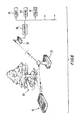
- FIG. 11 shows an alternative configuration for a data terminal.
- the terminal 10 contains generally all of the components discussed in relation to the other embodiments herein.
- the terminal 10 is configured in a “point and shoot” design and includes a grip portion 120 and a barrel portion 122 .
- the grip portion is configured to sit comfortably and easily, with optimum balance, in the user's hand and further carries a trigger 124 and a thumb wheel 126 .
- a display 128 and optional keypad 130 are provided on the upper face of the barrel portion 122 to allow easy viewing and input access to the user.
- the camera lens or other image recordal means are provided on the front face of the barrel portion 122 (not shown) allowing the user simply to point the terminal 10 in the direction it is desired to record in.
- zoom can be controlled by the thumb wheel 126 which is preferably located for optimum ease of use by the user's thumb when the grip portion 120 is held by the user.
- the processing speed and storage capabilities of the components of the data terminal can of course be determined according to the eventual cost of the system, for example a slower and hence cheaper microprocessor can be incorporated.
- the data terminal could additionally include an SRAM card to store the still images.
- the visual display screen 14 can, as shown in FIG. 9 include LCD (liquid crystal display) capabilities. Accordingly using a suitable pen 100 , the image can be altered for example by ringing or otherwise highlighting areas of interest, the alterations being represented on the LCD display as 102 in FIG. 9 . The alterations can be deleted or revised additionally using the keyboard as appropriate.
- a bar code symbol comprises one or more rows of light and dark regions, typically in the form of rectangles or, for the case of two-dimensional codes, in the form of a two-dimensional array of light and dark spaces.
- the dimensions of the dark and light regions indicate encoded information to be read.
- a bar code symbol reader illuminates the symbol using reading beam generating means and senses light reflective on the coded regions using reading beam detecting means to detect the dimensions of the coded regions.
- a decoder decodes the detected encoded information.
- Known symbols which include, for example, UPC/EAN, Coder 128, Codabar and Interleaved 2 of 5.
- One known type of bar code reader comprises a data wand as disclosed in U.S. Pat. No. 4,471,218, incorporated herein by reference.
- FIG. 10 shows a data terminal 10 of the type described herein above further incorporating an optical reader 110 incorporated in the data terminal 10 .
- the reader 110 includes reading beam generating and detecting means and the data terminal 10 includes processing means for decoding the detected encoded information.
- the reader 110 may comprise either a “flying-spot” laser scanner including means for scanning the reading beam or a “field of view” optical reader including a CCD array as detector. Both types of reader will be well known to the skilled reader and a full description of the components and operation is not provided here.
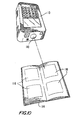
- FIG. 10 A particularly advantageous embodiment is shown in FIG. 10 .
- a book or other printer matter 114 is provided which can be carried by the user including printed bar codes 116 which are read by the reader 110 and the information contained therein utilised by the data terminal 10 .
- the data terminal 10 in fact comprises an Internet server capable of creating a web site at the data terminal carrying, for example, information relating to the external environment around the data terminal for access by users elsewhere on the Internet. In such circumstances the terminal might conventionally wish to download executable code from a host machine using an agent implementation language such as Java (a trade mark). This system can be cumbersome and time consuming in view of the level of communications required between the client and the host.
- the present invention solves this problem by storing the executable code (applets) in the form of two-dimensional high density bar codes 116 in the book 114 .
- Each bar code symbol 116 is identified by a suitable short title or other identifying information in the book.
- the user is merely required to read the two-dimensional bar code using the bar code reader 110 , and the executable code is immediately downloaded to the data terminal 10 for the data terminal 10 to use it as appropriate.
- the invention allows the user to carry a conventional book—for example having five hundred pages of 2-D applet codes. Such a book would not be cumbersome and would indeed be attractive to many users.
- the system allows greatly accelerated downloading of applets in as little as fifteen seconds. Conventional downloading systems would still be waiting for connection to the host in that range of time scale.
- any suitable executable code could be stored in a desired language in the two-dimensional bar codes 116 .
- a wide range of different applets could of course be stored according to this system and indexed appropriately. Indeed the system could be used for fixed or dedicated clients as well as the remote, mobile client data terminal shown in FIG. 10 .
- the data terminal can communicate with any suitable data network, for example an access point to the Internet, or to a closed dedicated system relating to the user or to which the user subscribes together with other users.
- Communication can be by way of RF communication or, if appropriate, infrared or microwave communication, or any other suitable wireless communication method.
Abstract
Description
Claims (9)
Priority Applications (1)
| Application Number | Priority Date | Filing Date | Title |
|---|---|---|---|
| US09/621,694 US6629642B1 (en) | 1996-08-02 | 2000-07-21 | Data system and method for accessing a computer network using a collection of bar code symbols |
Applications Claiming Priority (3)
| Application Number | Priority Date | Filing Date | Title |
|---|---|---|---|
| US69126396A | 1996-08-02 | 1996-08-02 | |
| US08/827,263 US6747692B2 (en) | 1997-03-28 | 1997-03-28 | Portable multipurpose recording terminal and portable network server |
| US09/621,694 US6629642B1 (en) | 1996-08-02 | 2000-07-21 | Data system and method for accessing a computer network using a collection of bar code symbols |
Related Parent Applications (1)
| Application Number | Title | Priority Date | Filing Date |
|---|---|---|---|
| US08/827,263 Continuation-In-Part US6747692B2 (en) | 1995-11-17 | 1997-03-28 | Portable multipurpose recording terminal and portable network server |
Publications (1)
| Publication Number | Publication Date |
|---|---|
| US6629642B1 true US6629642B1 (en) | 2003-10-07 |
Family
ID=28678453
Family Applications (1)
| Application Number | Title | Priority Date | Filing Date |
|---|---|---|---|
| US09/621,694 Expired - Lifetime US6629642B1 (en) | 1996-08-02 | 2000-07-21 | Data system and method for accessing a computer network using a collection of bar code symbols |
Country Status (1)
| Country | Link |
|---|---|
| US (1) | US6629642B1 (en) |
Cited By (49)
| Publication number | Priority date | Publication date | Assignee | Title |
|---|---|---|---|---|
| US20020027568A1 (en) * | 2000-09-06 | 2002-03-07 | Nec Corporation | Access method and system using small number of identifiers |
| US20020105575A1 (en) * | 2000-12-05 | 2002-08-08 | Hinde Stephen John | Enabling voice control of voice-controlled apparatus |
| US20030210423A1 (en) * | 2002-05-08 | 2003-11-13 | Stringham Gary G. | Network file printing |
| US20040000586A1 (en) * | 2000-10-05 | 2004-01-01 | Michael White | Logistics chain management system |
| US20050138205A1 (en) * | 2003-12-17 | 2005-06-23 | Schneider Automation Sas | Bar Coded Addressing Technique |
| US20050276462A1 (en) * | 2004-06-09 | 2005-12-15 | Silver William M | Method and apparatus for automatic visual event detection |
| US20050275834A1 (en) * | 2004-06-09 | 2005-12-15 | Silver William M | Method and apparatus for locating objects |
| US20050276461A1 (en) * | 2004-06-09 | 2005-12-15 | Silver William M | Method and apparatus for automatic visual detection, recording, and retrieval of events |
| US20050276459A1 (en) * | 2004-06-09 | 2005-12-15 | Andrew Eames | Method and apparatus for configuring and testing a machine vision detector |
| US20060079294A1 (en) * | 2004-10-07 | 2006-04-13 | Chen Alexander C | System, method and mobile unit to sense objects or text and retrieve related information |
| US20070069030A1 (en) * | 2005-09-28 | 2007-03-29 | Sauerwein James T Jr | Data collection device and network having radio signal responsive mode switching |
| US20070086668A1 (en) * | 2005-10-14 | 2007-04-19 | Ackley Jonathan M | Systems and methods for information content delivery relating to an object |
| US20070086638A1 (en) * | 2005-10-14 | 2007-04-19 | Disney Enterprises, Inc. | Systems and methods for obtaining information associated with an image |
| US20070084928A1 (en) * | 2005-10-14 | 2007-04-19 | Ackley Jonathan M | Systems and methods for decoding an image to determine a digital identifier |
| US20070138270A1 (en) * | 2005-12-20 | 2007-06-21 | United States Postal Service | Method and system for interrogating and processing codes |
| US20080011855A1 (en) * | 2006-07-17 | 2008-01-17 | Sateesha Nadabar | Method and Apparatus for Multiplexed Symbol Decoding |
| EP1914933A1 (en) * | 2006-10-19 | 2008-04-23 | Ericsson AB | Method and apparatus for retransmission request reduction in a network |
| US20080110991A1 (en) * | 2006-11-15 | 2008-05-15 | Bellsouth Intellectual Property Corporation | Apparatus and methods for providing active functions using encoded two-dimensional arrays |
| WO2008097071A1 (en) * | 2007-02-06 | 2008-08-14 | Nexbis Sdn. Bhd. | Mobile information retrieval over wireless network |
| US20090020612A1 (en) * | 2007-06-28 | 2009-01-22 | Symbol Technologies, Inc. | Imaging dual window scanner with presentation scanning |
| US20090026271A1 (en) * | 2007-06-28 | 2009-01-29 | Symbol Technologies, Inc. | Bar code readers having multifold mirrors |
| US20090084854A1 (en) * | 2007-09-27 | 2009-04-02 | Symbol Technologies, Inc. | Multiple Camera Imaging-Based Bar Code Reader |
| US7577516B2 (en) | 2006-05-09 | 2009-08-18 | Hand Held Products, Inc. | Power management apparatus and methods for portable data terminals |
| US20100001075A1 (en) * | 2008-07-07 | 2010-01-07 | Symbol Technologies, Inc. | Multi-imaging scanner for reading images |
| US20100046486A1 (en) * | 2006-09-06 | 2010-02-25 | Panasonic Corporation | Wireless communication system |
| US7686222B2 (en) | 2001-07-13 | 2010-03-30 | Hand Held Products, Inc. | Optical reader having a color imager |
| US20100102129A1 (en) * | 2008-10-29 | 2010-04-29 | Symbol Technologies, Inc. | Bar code reader with split field of view |
| US20100116887A1 (en) * | 2008-11-07 | 2010-05-13 | Symbol Technologies, Inc. | Identification of non-barcoded products |
| US7908272B2 (en) | 2006-03-08 | 2011-03-15 | Sunplus Technology Co., Ltd. | Universal information code format for two dimensional bar code and interactive information exchange system using the same |
| US7957554B1 (en) | 2002-12-31 | 2011-06-07 | Cognex Technology And Investment Corporation | Method and apparatus for human interface to a machine vision system |
| US7963448B2 (en) | 2004-12-22 | 2011-06-21 | Cognex Technology And Investment Corporation | Hand held machine vision method and apparatus |
| US7967207B1 (en) * | 2000-07-18 | 2011-06-28 | Bartex Research, Llc | Bar code data entry device |
| US8027802B1 (en) | 2006-06-29 | 2011-09-27 | Cognex Corporation | Method and apparatus for verifying two dimensional mark quality |
| US8169478B2 (en) | 2006-12-14 | 2012-05-01 | Cognex Corporation | Method and apparatus for calibrating a mark verifier |
| US20130028116A1 (en) * | 2001-11-19 | 2013-01-31 | At&T Intellectual Property Ii, L.P. | WLAN Having Load Balancing Based on Access Point Loading |
| US8439262B2 (en) | 2001-05-15 | 2013-05-14 | Hand Held Products, Inc. | Image capture apparatus and method |
| USRE44353E1 (en) | 2004-11-12 | 2013-07-09 | Cognex Technology And Investment Corporation | System and method for assigning analysis parameters to vision detector using a graphical interface |
| US8582925B2 (en) | 2004-11-12 | 2013-11-12 | Cognex Technology And Investment Corporation | System and method for displaying and using non-numeric graphic elements to control and monitor a vision system |
| US8657200B2 (en) | 2011-06-20 | 2014-02-25 | Metrologic Instruments, Inc. | Indicia reading terminal with color frame processing |
| US8782553B2 (en) | 2004-06-09 | 2014-07-15 | Cognex Corporation | Human-machine-interface and method for manipulating data in a machine vision system |
| US9292187B2 (en) | 2004-11-12 | 2016-03-22 | Cognex Corporation | System, method and graphical user interface for displaying and controlling vision system operating parameters |
| US9436769B2 (en) * | 2014-11-26 | 2016-09-06 | Dropbox, Inc. | Automatic device upload configuration |
| US9521505B2 (en) | 1997-10-15 | 2016-12-13 | Nokia Technologies Oy | Mobile telephone for internet applications |
| US9552506B1 (en) | 2004-12-23 | 2017-01-24 | Cognex Technology And Investment Llc | Method and apparatus for industrial identification mark verification |
| US9582792B2 (en) | 2013-07-29 | 2017-02-28 | Exxonmobil Research And Engineering Company | System and method to purchase and dispense fuel and other products using a mobile device with improved user experience |
| US9651499B2 (en) | 2011-12-20 | 2017-05-16 | Cognex Corporation | Configurable image trigger for a vision system and method for using the same |
| US9734376B2 (en) | 2007-11-13 | 2017-08-15 | Cognex Corporation | System and method for reading patterns using multiple image frames |
| US10510084B2 (en) | 2011-07-21 | 2019-12-17 | United States Postal Service | System and method for retrieving content associated with distribution items |
| US11153472B2 (en) | 2005-10-17 | 2021-10-19 | Cutting Edge Vision, LLC | Automatic upload of pictures from a camera |
Citations (43)
| Publication number | Priority date | Publication date | Assignee | Title |
|---|---|---|---|---|
| US3981566A (en) | 1974-09-23 | 1976-09-21 | Eastman Kodak Company | Lever-action mountings for beam steerer mirrors |
| US4157861A (en) | 1977-08-03 | 1979-06-12 | The United States Of America As Represented By The Secretary Of The Navy | Optical beam steering system |
| US4866257A (en) | 1987-11-19 | 1989-09-12 | Spectra-Physics, Inc. | Bar code scanner and method |
| US4868375A (en) | 1988-08-22 | 1989-09-19 | Ncr Corporation | Method for changing the functions of a bar code reader |
| US4947261A (en) | 1987-07-08 | 1990-08-07 | Sharp Kabushiki Kaisha | Portable image input device |
| US5061914A (en) | 1989-06-27 | 1991-10-29 | Tini Alloy Company | Shape-memory alloy micro-actuator |
| US5083218A (en) | 1989-02-08 | 1992-01-21 | Casio Computer Co., Ltd. | Hand-held image reading apparatus |
| US5097354A (en) | 1989-07-27 | 1992-03-17 | Omron Corporation | Beam scanner |
| US5288976A (en) | 1991-07-15 | 1994-02-22 | Nynex Corporation | Bar code use in information, transactional and other system and service applications |
| US5301243A (en) | 1990-12-21 | 1994-04-05 | Francis Olschafskie | Hand-held character-oriented scanner with external view area |
| US5331547A (en) | 1993-01-29 | 1994-07-19 | Clinical Multiphase Research, Inc. | Process and computer system for control of interface software and data files |
| US5448046A (en) | 1987-12-28 | 1995-09-05 | Symbol Technologies, Inc. | Arrangement for and method of expediting commercial product transactions at a point-of-sale site |
| US5477043A (en) | 1989-10-30 | 1995-12-19 | Symbol Technologies, Inc. | Scanning arrangement for the implementation of scanning patterns over indicia by driving the scanning elements in different component directions |
| US5483052A (en) | 1993-12-07 | 1996-01-09 | Smith, Iii; Herbert J. | System for reading, storing and using bar-encoded data from a coded business card or other printed material |
| US5490217A (en) | 1993-03-05 | 1996-02-06 | Metanetics Corporation | Automatic document handling system |
| US5543956A (en) | 1992-10-08 | 1996-08-06 | Fuji Electric Co., Ltd. | Torsional vibrators and light deflectors using the torsional vibrator |
| US5574804A (en) | 1990-12-21 | 1996-11-12 | Olschafskie; Francis | Hand-held scanner |
| US5579148A (en) | 1993-11-29 | 1996-11-26 | Nippondenso Co., Ltd. | Two-dimensional optical scanner |
| EP0744856A2 (en) | 1995-05-26 | 1996-11-27 | AT&T IPM Corp. | Apparatus for and method of utilizing product identifier codes to establish communication connections |
| US5581070A (en) | 1989-10-30 | 1996-12-03 | Symbol Technologies, Inc. | Omni-directional scan pattern generator in electro-optical scanners |
| US5594232A (en) | 1995-05-05 | 1997-01-14 | Symbol Technologies, Inc. | Planar arrangement for two-dimensional optical scanning |
| US5595445A (en) | 1995-12-27 | 1997-01-21 | Bobry; Howard H. | Hand-held optical scanner |
| US5600833A (en) | 1993-09-17 | 1997-02-04 | Digital Equipment Corp. | Attribute portion based document retrieval system with system query language interface |
| US5606447A (en) | 1993-12-20 | 1997-02-25 | The Nippon Signal Co., Ltd. | Planar type mirror galvanometer and method of manufacture |
| US5614706A (en) | 1992-05-15 | 1997-03-25 | Symbol Technologies, Inc. | Bar code scanning assembly with cantilevered or torsionally vibrating flexural member |
| US5629790A (en) | 1993-10-18 | 1997-05-13 | Neukermans; Armand P. | Micromachined torsional scanner |
| US5635694A (en) | 1995-09-27 | 1997-06-03 | Xerox Corporation | System and method for embedding machine coded destination information into a postal mark |
| US5640193A (en) | 1994-08-15 | 1997-06-17 | Lucent Technologies Inc. | Multimedia service access by reading marks on an object |
| US5663808A (en) | 1994-12-27 | 1997-09-02 | Samsung Electronics Co., Ltd. | Device and method for automatically transmitting documents in a facsimile system |
| US5673139A (en) | 1993-07-19 | 1997-09-30 | Medcom, Inc. | Microelectromechanical television scanning device and method for making the same |
| US5767666A (en) | 1994-01-31 | 1998-06-16 | The Nippon Signal Co., Ltd | Planar type mirror galvanometer incorpotating a displacement detection function |
| US5799219A (en) | 1996-02-20 | 1998-08-25 | Eastman Kodak Company | System and method for remote image communication and processing using data recorded on photographic film |
| US5804803A (en) | 1996-04-02 | 1998-09-08 | International Business Machines Corporation | Mechanism for retrieving information using data encoded on an object |
| US5821523A (en) | 1992-03-12 | 1998-10-13 | Bunte; Alan G. | Combined code reader and digital camera using a common photodetector |
| US5837987A (en) | 1986-08-08 | 1998-11-17 | Norand Technology Corporation | Hand-held optically readable character set reader having automatic focus control for operating over a range of distances |
| US5870088A (en) | 1996-05-09 | 1999-02-09 | National Instruments Corporation | System and method for editing a control via direct graphical user interaction |
| US5905248A (en) | 1990-09-11 | 1999-05-18 | Metrologic Instruments, Inc. | System and method for carrying out information-related transactions using web documents embodying transaction enabling applets automatically launched and executed in response to reading URL-encoded symbols pointing thereto |
| US5923735A (en) | 1996-05-29 | 1999-07-13 | Symbol Technologies, Inc. | Self-service checkout system utilizing portable self-checkout communications terminal |
| US5978773A (en) | 1995-06-20 | 1999-11-02 | Neomedia Technologies, Inc. | System and method for using an ordinary article of commerce to access a remote computer |
| US6012102A (en) | 1996-04-02 | 2000-01-04 | Infogear Technology Corporation | System using machine-readable printed symbols created from encoded data resource specifiers to establish connection to data resource on data communications network |
| US6014240A (en) | 1998-12-01 | 2000-01-11 | Xerox Corporation | Method and apparatus for an integrated laser beam scanner using a carrier substrate |
| US6081629A (en) | 1997-09-17 | 2000-06-27 | Browning; Denton R. | Handheld scanner and accompanying remote access agent |
| US6378073B1 (en) * | 1997-12-22 | 2002-04-23 | Motorola, Inc. | Single account portable wireless financial messaging unit |
-
2000
- 2000-07-21 US US09/621,694 patent/US6629642B1/en not_active Expired - Lifetime
Patent Citations (46)
| Publication number | Priority date | Publication date | Assignee | Title |
|---|---|---|---|---|
| US3981566A (en) | 1974-09-23 | 1976-09-21 | Eastman Kodak Company | Lever-action mountings for beam steerer mirrors |
| US4157861A (en) | 1977-08-03 | 1979-06-12 | The United States Of America As Represented By The Secretary Of The Navy | Optical beam steering system |
| US5837987A (en) | 1986-08-08 | 1998-11-17 | Norand Technology Corporation | Hand-held optically readable character set reader having automatic focus control for operating over a range of distances |
| US4947261A (en) | 1987-07-08 | 1990-08-07 | Sharp Kabushiki Kaisha | Portable image input device |
| US4866257A (en) | 1987-11-19 | 1989-09-12 | Spectra-Physics, Inc. | Bar code scanner and method |
| US4866257C1 (en) | 1987-11-19 | 2001-01-09 | Spectra Physics Scanning Syst | Bar code scanner and method |
| US5448046A (en) | 1987-12-28 | 1995-09-05 | Symbol Technologies, Inc. | Arrangement for and method of expediting commercial product transactions at a point-of-sale site |
| US4868375A (en) | 1988-08-22 | 1989-09-19 | Ncr Corporation | Method for changing the functions of a bar code reader |
| US5083218A (en) | 1989-02-08 | 1992-01-21 | Casio Computer Co., Ltd. | Hand-held image reading apparatus |
| US5061914A (en) | 1989-06-27 | 1991-10-29 | Tini Alloy Company | Shape-memory alloy micro-actuator |
| US5097354A (en) | 1989-07-27 | 1992-03-17 | Omron Corporation | Beam scanner |
| US5477043A (en) | 1989-10-30 | 1995-12-19 | Symbol Technologies, Inc. | Scanning arrangement for the implementation of scanning patterns over indicia by driving the scanning elements in different component directions |
| US5481099A (en) | 1989-10-30 | 1996-01-02 | Symbol Technologies, Inc. | Scanning arrangement for the implementation of omni-directional scanning patterns over indicia |
| US5581070A (en) | 1989-10-30 | 1996-12-03 | Symbol Technologies, Inc. | Omni-directional scan pattern generator in electro-optical scanners |
| US5905248A (en) | 1990-09-11 | 1999-05-18 | Metrologic Instruments, Inc. | System and method for carrying out information-related transactions using web documents embodying transaction enabling applets automatically launched and executed in response to reading URL-encoded symbols pointing thereto |
| US5301243A (en) | 1990-12-21 | 1994-04-05 | Francis Olschafskie | Hand-held character-oriented scanner with external view area |
| US5574804A (en) | 1990-12-21 | 1996-11-12 | Olschafskie; Francis | Hand-held scanner |
| US5288976A (en) | 1991-07-15 | 1994-02-22 | Nynex Corporation | Bar code use in information, transactional and other system and service applications |
| US5821523A (en) | 1992-03-12 | 1998-10-13 | Bunte; Alan G. | Combined code reader and digital camera using a common photodetector |
| US5614706A (en) | 1992-05-15 | 1997-03-25 | Symbol Technologies, Inc. | Bar code scanning assembly with cantilevered or torsionally vibrating flexural member |
| US5543956A (en) | 1992-10-08 | 1996-08-06 | Fuji Electric Co., Ltd. | Torsional vibrators and light deflectors using the torsional vibrator |
| US5331547A (en) | 1993-01-29 | 1994-07-19 | Clinical Multiphase Research, Inc. | Process and computer system for control of interface software and data files |
| US5490217A (en) | 1993-03-05 | 1996-02-06 | Metanetics Corporation | Automatic document handling system |
| US5673139A (en) | 1993-07-19 | 1997-09-30 | Medcom, Inc. | Microelectromechanical television scanning device and method for making the same |
| US5600833A (en) | 1993-09-17 | 1997-02-04 | Digital Equipment Corp. | Attribute portion based document retrieval system with system query language interface |
| US5629790A (en) | 1993-10-18 | 1997-05-13 | Neukermans; Armand P. | Micromachined torsional scanner |
| US5579148A (en) | 1993-11-29 | 1996-11-26 | Nippondenso Co., Ltd. | Two-dimensional optical scanner |
| US5483052A (en) | 1993-12-07 | 1996-01-09 | Smith, Iii; Herbert J. | System for reading, storing and using bar-encoded data from a coded business card or other printed material |
| US5606447A (en) | 1993-12-20 | 1997-02-25 | The Nippon Signal Co., Ltd. | Planar type mirror galvanometer and method of manufacture |
| US5767666A (en) | 1994-01-31 | 1998-06-16 | The Nippon Signal Co., Ltd | Planar type mirror galvanometer incorpotating a displacement detection function |
| US5640193A (en) | 1994-08-15 | 1997-06-17 | Lucent Technologies Inc. | Multimedia service access by reading marks on an object |
| US5663808A (en) | 1994-12-27 | 1997-09-02 | Samsung Electronics Co., Ltd. | Device and method for automatically transmitting documents in a facsimile system |
| US5594232A (en) | 1995-05-05 | 1997-01-14 | Symbol Technologies, Inc. | Planar arrangement for two-dimensional optical scanning |
| EP0744856A2 (en) | 1995-05-26 | 1996-11-27 | AT&T IPM Corp. | Apparatus for and method of utilizing product identifier codes to establish communication connections |
| US6199048B1 (en) | 1995-06-20 | 2001-03-06 | Neomedia Technologies, Inc. | System and method for automatic access of a remote computer over a network |
| US5978773A (en) | 1995-06-20 | 1999-11-02 | Neomedia Technologies, Inc. | System and method for using an ordinary article of commerce to access a remote computer |
| US5635694A (en) | 1995-09-27 | 1997-06-03 | Xerox Corporation | System and method for embedding machine coded destination information into a postal mark |
| US5595445A (en) | 1995-12-27 | 1997-01-21 | Bobry; Howard H. | Hand-held optical scanner |
| US5799219A (en) | 1996-02-20 | 1998-08-25 | Eastman Kodak Company | System and method for remote image communication and processing using data recorded on photographic film |
| US6012102A (en) | 1996-04-02 | 2000-01-04 | Infogear Technology Corporation | System using machine-readable printed symbols created from encoded data resource specifiers to establish connection to data resource on data communications network |
| US5804803A (en) | 1996-04-02 | 1998-09-08 | International Business Machines Corporation | Mechanism for retrieving information using data encoded on an object |
| US5870088A (en) | 1996-05-09 | 1999-02-09 | National Instruments Corporation | System and method for editing a control via direct graphical user interaction |
| US5923735A (en) | 1996-05-29 | 1999-07-13 | Symbol Technologies, Inc. | Self-service checkout system utilizing portable self-checkout communications terminal |
| US6081629A (en) | 1997-09-17 | 2000-06-27 | Browning; Denton R. | Handheld scanner and accompanying remote access agent |
| US6378073B1 (en) * | 1997-12-22 | 2002-04-23 | Motorola, Inc. | Single account portable wireless financial messaging unit |
| US6014240A (en) | 1998-12-01 | 2000-01-11 | Xerox Corporation | Method and apparatus for an integrated laser beam scanner using a carrier substrate |
Non-Patent Citations (8)
| Title |
|---|
| "Distributing Uniform Resource Locators as Bar Code Images," IBM Technical Disclosure Bulletin, vol. 39, No. 1, Jan. 1996. |
| Abstract of PCT Publication No.: 00060484 WO, Hunter et al., "System and Method of Using Machine-Readable or Human-Readable Linkage Codes for Accessing Networked Data Resources," Oct. 12, 2000. |
| Abstract of PCT Publication No.: 09820411 WO, Durst et al., "Automatic Access of Electronic Information Through Machine-Readable Codes on Printed Documents," May 14, 1998. |
| Abstract of PCT Publication No.: 09904326 WO, Durst et al., "Printed Coupons with Embedded Discounts for Online Purchases," Jan. 28, 1999. |
| Abstract of PCT Publication No.: 09913391 WO, Christiansen et al., "Improved Secure Documents," Mar. 18, 1999. |
| B. Schilit, et al., "TeleWeb: Loosely connected access to the World Wide Web," Computer Networks and ISDN Systems 28 (1996) pp. 1431-1444. |
| H. Shrikumar et al., "Thinternet: life at the end of a tether," Computer Networks and ISDN Systems 27 (1994) pp. 375-385. |
| M. Hahn, Uniform Resource Locators, EDPACS, Dec. 1995, pp. 8-13. |
Cited By (110)
| Publication number | Priority date | Publication date | Assignee | Title |
|---|---|---|---|---|
| US9521505B2 (en) | 1997-10-15 | 2016-12-13 | Nokia Technologies Oy | Mobile telephone for internet applications |
| US7967207B1 (en) * | 2000-07-18 | 2011-06-28 | Bartex Research, Llc | Bar code data entry device |
| US8763907B2 (en) | 2000-07-18 | 2014-07-01 | Cutting Edge Codes Llc | Barcode device |
| US8746565B2 (en) | 2000-07-18 | 2014-06-10 | Cutting Edge Codes, LLC | Barcode device |
| US8733658B2 (en) | 2000-07-18 | 2014-05-27 | Cutting Edge Codes Llc | Barcode device |
| US8733657B2 (en) | 2000-07-18 | 2014-05-27 | Cutting Edge Codes Llc | Barcode device |
| US7093014B2 (en) * | 2000-09-06 | 2006-08-15 | Nec Corporation | Access method and system with restricted number of address indentifiers in domain areas for identifying server addresses |
| US20020027568A1 (en) * | 2000-09-06 | 2002-03-07 | Nec Corporation | Access method and system using small number of identifiers |
| US20040000586A1 (en) * | 2000-10-05 | 2004-01-01 | Michael White | Logistics chain management system |
| US6764004B2 (en) * | 2000-10-05 | 2004-07-20 | Exago Pty Ltd. | Logistics chain management system |
| US20020105575A1 (en) * | 2000-12-05 | 2002-08-08 | Hinde Stephen John | Enabling voice control of voice-controlled apparatus |
| US6970824B2 (en) * | 2000-12-05 | 2005-11-29 | Hewlett-Packard Development Company, L.P. | Enabling voice control of voice-controlled apparatus using a head mounted camera system |
| US8794522B2 (en) | 2001-05-15 | 2014-08-05 | Hand Held Products, Inc. | Image capture apparatus and method |
| US8439262B2 (en) | 2001-05-15 | 2013-05-14 | Hand Held Products, Inc. | Image capture apparatus and method |
| US8528818B2 (en) | 2001-07-13 | 2013-09-10 | Hand Held Products, Inc. | Optical reader having an imager |
| US8292180B2 (en) | 2001-07-13 | 2012-10-23 | Hand Held Products, Inc. | Optical reader having an imager |
| US7686222B2 (en) | 2001-07-13 | 2010-03-30 | Hand Held Products, Inc. | Optical reader having a color imager |
| US20130028116A1 (en) * | 2001-11-19 | 2013-01-31 | At&T Intellectual Property Ii, L.P. | WLAN Having Load Balancing Based on Access Point Loading |
| US8934368B2 (en) * | 2001-11-19 | 2015-01-13 | At&T Intellectual Property Ii, L.P. | WLAN having load balancing based on access point loading |
| US7107368B2 (en) * | 2002-05-08 | 2006-09-12 | Hewlett-Packard Development Company, L.P. | Systems and methods for printing |
| US20030210423A1 (en) * | 2002-05-08 | 2003-11-13 | Stringham Gary G. | Network file printing |
| US8625880B2 (en) | 2002-12-31 | 2014-01-07 | Cognex Technology And Investment Corporation | Method and apparatus for human interface to a machine vision system |
| US7957554B1 (en) | 2002-12-31 | 2011-06-07 | Cognex Technology And Investment Corporation | Method and apparatus for human interface to a machine vision system |
| US20050138205A1 (en) * | 2003-12-17 | 2005-06-23 | Schneider Automation Sas | Bar Coded Addressing Technique |
| US20050275834A1 (en) * | 2004-06-09 | 2005-12-15 | Silver William M | Method and apparatus for locating objects |
| US9092841B2 (en) | 2004-06-09 | 2015-07-28 | Cognex Technology And Investment Llc | Method and apparatus for visual detection and inspection of objects |
| US9094588B2 (en) | 2004-06-09 | 2015-07-28 | Cognex Corporation | Human machine-interface and method for manipulating data in a machine vision system |
| US8630478B2 (en) | 2004-06-09 | 2014-01-14 | Cognex Technology And Investment Corporation | Method and apparatus for locating objects |
| US20080036873A1 (en) * | 2004-06-09 | 2008-02-14 | Cognex Corporation | System for configuring an optoelectronic sensor |
| US8249297B2 (en) | 2004-06-09 | 2012-08-21 | Cognex Technology And Investment Corporation | Method and apparatus for automatic visual event detection |
| US8249329B2 (en) | 2004-06-09 | 2012-08-21 | Cognex Technology And Investment Corporation | Method and apparatus for detecting and characterizing an object |
| US8243986B2 (en) | 2004-06-09 | 2012-08-14 | Cognex Technology And Investment Corporation | Method and apparatus for automatic visual event detection |
| US8891852B2 (en) | 2004-06-09 | 2014-11-18 | Cognex Technology And Investment Corporation | Method and apparatus for configuring and testing a machine vision detector |
| US20050276460A1 (en) * | 2004-06-09 | 2005-12-15 | Silver William M | Method and apparatus for automatic visual event detection |
| US8290238B2 (en) | 2004-06-09 | 2012-10-16 | Cognex Technology And Investment Corporation | Method and apparatus for locating objects |
| US9183443B2 (en) | 2004-06-09 | 2015-11-10 | Cognex Technology And Investment Llc | Method and apparatus for configuring and testing a machine vision detector |
| US20050276462A1 (en) * | 2004-06-09 | 2005-12-15 | Silver William M | Method and apparatus for automatic visual event detection |
| US20050275831A1 (en) * | 2004-06-09 | 2005-12-15 | Silver William M | Method and apparatus for visual detection and inspection of objects |
| US20050276459A1 (en) * | 2004-06-09 | 2005-12-15 | Andrew Eames | Method and apparatus for configuring and testing a machine vision detector |
| US8782553B2 (en) | 2004-06-09 | 2014-07-15 | Cognex Corporation | Human-machine-interface and method for manipulating data in a machine vision system |
| US8249296B2 (en) | 2004-06-09 | 2012-08-21 | Cognex Technology And Investment Corporation | Method and apparatus for automatic visual event detection |
| US20050276461A1 (en) * | 2004-06-09 | 2005-12-15 | Silver William M | Method and apparatus for automatic visual detection, recording, and retrieval of events |
| US8422729B2 (en) | 2004-06-09 | 2013-04-16 | Cognex Corporation | System for configuring an optoelectronic sensor |
| US20090061949A1 (en) * | 2004-10-07 | 2009-03-05 | Chen Alexander C | System, method and mobile unit to sense objects or text and retrieve related information |
| US8145256B2 (en) | 2004-10-07 | 2012-03-27 | Rpx Corporation | System, method and mobile unit to sense objects or text and retrieve related information |
| US7450960B2 (en) * | 2004-10-07 | 2008-11-11 | Chen Alexander C | System, method and mobile unit to sense objects or text and retrieve related information |
| US20060079294A1 (en) * | 2004-10-07 | 2006-04-13 | Chen Alexander C | System, method and mobile unit to sense objects or text and retrieve related information |
| US8582925B2 (en) | 2004-11-12 | 2013-11-12 | Cognex Technology And Investment Corporation | System and method for displaying and using non-numeric graphic elements to control and monitor a vision system |
| USRE44353E1 (en) | 2004-11-12 | 2013-07-09 | Cognex Technology And Investment Corporation | System and method for assigning analysis parameters to vision detector using a graphical interface |
| US9292187B2 (en) | 2004-11-12 | 2016-03-22 | Cognex Corporation | System, method and graphical user interface for displaying and controlling vision system operating parameters |
| US9798910B2 (en) | 2004-12-22 | 2017-10-24 | Cognex Corporation | Mobile hand held machine vision method and apparatus using data from multiple images to perform processes |
| US7963448B2 (en) | 2004-12-22 | 2011-06-21 | Cognex Technology And Investment Corporation | Hand held machine vision method and apparatus |
| US10061946B2 (en) | 2004-12-23 | 2018-08-28 | Cognex Technology And Investment Llc | Method and apparatus for industrial identification mark verification |
| US9552506B1 (en) | 2004-12-23 | 2017-01-24 | Cognex Technology And Investment Llc | Method and apparatus for industrial identification mark verification |
| US8281993B2 (en) | 2005-09-28 | 2012-10-09 | Hand Held Products, Inc. | Data collection device and network having radio signal responsive operation |
| US20100217723A1 (en) * | 2005-09-28 | 2010-08-26 | Hand Held Products, Inc. | Data collection device and network having radio signal responsive operation |
| US8157168B2 (en) | 2005-09-28 | 2012-04-17 | Hand Held Products, Inc. | Data collection device and network having radio signal responsive operation |
| US20070069030A1 (en) * | 2005-09-28 | 2007-03-29 | Sauerwein James T Jr | Data collection device and network having radio signal responsive mode switching |
| US7712670B2 (en) | 2005-09-28 | 2010-05-11 | Sauerwein Jr James T | Data collection device and network having radio signal responsive mode switching |
| US7801359B2 (en) | 2005-10-14 | 2010-09-21 | Disney Enterprise, Inc. | Systems and methods for obtaining information associated with an image |
| US7480422B2 (en) | 2005-10-14 | 2009-01-20 | Disney Enterprises, Inc. | Systems and methods for information content delivery relating to an object |
| US20070086668A1 (en) * | 2005-10-14 | 2007-04-19 | Ackley Jonathan M | Systems and methods for information content delivery relating to an object |
| US8023746B2 (en) | 2005-10-14 | 2011-09-20 | Disney Enterprises, Inc. | Systems and methods for decoding an image to determine a digital identifier |
| US20070086638A1 (en) * | 2005-10-14 | 2007-04-19 | Disney Enterprises, Inc. | Systems and methods for obtaining information associated with an image |
| US20070084928A1 (en) * | 2005-10-14 | 2007-04-19 | Ackley Jonathan M | Systems and methods for decoding an image to determine a digital identifier |
| US11818458B2 (en) | 2005-10-17 | 2023-11-14 | Cutting Edge Vision, LLC | Camera touchpad |
| US11153472B2 (en) | 2005-10-17 | 2021-10-19 | Cutting Edge Vision, LLC | Automatic upload of pictures from a camera |
| US20070138270A1 (en) * | 2005-12-20 | 2007-06-21 | United States Postal Service | Method and system for interrogating and processing codes |
| WO2007075958A3 (en) * | 2005-12-20 | 2008-01-17 | Us Postal Service | Method and system for interrogating and processing codes |
| US10192209B2 (en) | 2005-12-20 | 2019-01-29 | United States Postal Service | Method and system for interrogating and processing codes |
| US8925810B2 (en) | 2005-12-20 | 2015-01-06 | United States Postal Service | Methods and systems for interrogating and processing codes |
| US10460304B2 (en) | 2005-12-20 | 2019-10-29 | United States Postal Service | Method and system for interrogating and processing codes |
| US10825011B2 (en) | 2005-12-20 | 2020-11-03 | United States Postal Service | Method and system for interrogating and processing codes |
| US8936192B2 (en) * | 2005-12-20 | 2015-01-20 | United States Postal Service | Method and system for interrogating and processing codes |
| US9449317B2 (en) | 2005-12-20 | 2016-09-20 | United States Postal Service | Method and system for interrogating and processing codes |
| WO2007075958A2 (en) * | 2005-12-20 | 2007-07-05 | United States Postal Service | Method and system for interrogating and processing codes |
| US9147186B2 (en) | 2005-12-20 | 2015-09-29 | The United States of America Postal Service | Method and system for interrogating and processing codes |
| US7908272B2 (en) | 2006-03-08 | 2011-03-15 | Sunplus Technology Co., Ltd. | Universal information code format for two dimensional bar code and interactive information exchange system using the same |
| US7577516B2 (en) | 2006-05-09 | 2009-08-18 | Hand Held Products, Inc. | Power management apparatus and methods for portable data terminals |
| US8108176B2 (en) | 2006-06-29 | 2012-01-31 | Cognex Corporation | Method and apparatus for verifying two dimensional mark quality |
| US8027802B1 (en) | 2006-06-29 | 2011-09-27 | Cognex Corporation | Method and apparatus for verifying two dimensional mark quality |
| US9465962B2 (en) | 2006-06-29 | 2016-10-11 | Cognex Corporation | Method and apparatus for verifying two dimensional mark quality |
| US20080011855A1 (en) * | 2006-07-17 | 2008-01-17 | Sateesha Nadabar | Method and Apparatus for Multiplexed Symbol Decoding |
| US7984854B2 (en) | 2006-07-17 | 2011-07-26 | Cognex Corporation | Method and apparatus for multiplexed symbol decoding |
| US8243702B2 (en) * | 2006-09-06 | 2012-08-14 | Panasonic Corporation | Wireless communication system |
| US20100046486A1 (en) * | 2006-09-06 | 2010-02-25 | Panasonic Corporation | Wireless communication system |
| US20080098089A1 (en) * | 2006-10-19 | 2008-04-24 | Ericsson, Inc. | Method and apparatus for retransmission request reduction in a network |
| EP1914933A1 (en) * | 2006-10-19 | 2008-04-23 | Ericsson AB | Method and apparatus for retransmission request reduction in a network |
| US20080110991A1 (en) * | 2006-11-15 | 2008-05-15 | Bellsouth Intellectual Property Corporation | Apparatus and methods for providing active functions using encoded two-dimensional arrays |
| US8169478B2 (en) | 2006-12-14 | 2012-05-01 | Cognex Corporation | Method and apparatus for calibrating a mark verifier |
| WO2008097071A1 (en) * | 2007-02-06 | 2008-08-14 | Nexbis Sdn. Bhd. | Mobile information retrieval over wireless network |
| US20090026271A1 (en) * | 2007-06-28 | 2009-01-29 | Symbol Technologies, Inc. | Bar code readers having multifold mirrors |
| US8505824B2 (en) | 2007-06-28 | 2013-08-13 | Symbol Technologies, Inc. | Bar code readers having multifold mirrors |
| US20090020612A1 (en) * | 2007-06-28 | 2009-01-22 | Symbol Technologies, Inc. | Imaging dual window scanner with presentation scanning |
| US20090084854A1 (en) * | 2007-09-27 | 2009-04-02 | Symbol Technologies, Inc. | Multiple Camera Imaging-Based Bar Code Reader |
| US8662397B2 (en) | 2007-09-27 | 2014-03-04 | Symbol Technologies, Inc. | Multiple camera imaging-based bar code reader |
| US9734376B2 (en) | 2007-11-13 | 2017-08-15 | Cognex Corporation | System and method for reading patterns using multiple image frames |
| US10592715B2 (en) | 2007-11-13 | 2020-03-17 | Cognex Corporation | System and method for reading patterns using multiple image frames |
| US20100001075A1 (en) * | 2008-07-07 | 2010-01-07 | Symbol Technologies, Inc. | Multi-imaging scanner for reading images |
| US20100102129A1 (en) * | 2008-10-29 | 2010-04-29 | Symbol Technologies, Inc. | Bar code reader with split field of view |
| US20100116887A1 (en) * | 2008-11-07 | 2010-05-13 | Symbol Technologies, Inc. | Identification of non-barcoded products |
| US8479996B2 (en) | 2008-11-07 | 2013-07-09 | Symbol Technologies, Inc. | Identification of non-barcoded products |
| US8910875B2 (en) | 2011-06-20 | 2014-12-16 | Metrologic Instruments, Inc. | Indicia reading terminal with color frame processing |
| US8657200B2 (en) | 2011-06-20 | 2014-02-25 | Metrologic Instruments, Inc. | Indicia reading terminal with color frame processing |
| US11423419B2 (en) | 2011-07-21 | 2022-08-23 | United States Postal Service | System and method for retrieving content associated with distribution items |
| US11836745B2 (en) | 2011-07-21 | 2023-12-05 | United States Postal Service | System and method for retrieving content associated with distribution items |
| US10510084B2 (en) | 2011-07-21 | 2019-12-17 | United States Postal Service | System and method for retrieving content associated with distribution items |
| US9651499B2 (en) | 2011-12-20 | 2017-05-16 | Cognex Corporation | Configurable image trigger for a vision system and method for using the same |
| US9582792B2 (en) | 2013-07-29 | 2017-02-28 | Exxonmobil Research And Engineering Company | System and method to purchase and dispense fuel and other products using a mobile device with improved user experience |
| US9436769B2 (en) * | 2014-11-26 | 2016-09-06 | Dropbox, Inc. | Automatic device upload configuration |
Similar Documents
| Publication | Publication Date | Title |
|---|---|---|
| US6629642B1 (en) | Data system and method for accessing a computer network using a collection of bar code symbols | |
| US7032001B1 (en) | Site-hosting, mobile terminal for wireless connection to computer network | |
| US7092369B2 (en) | Communications network with wireless gateways for mobile terminal access | |
| US7305478B2 (en) | Bar code symbol ticketing for authorizing access in a wireless local area communications network | |
| CN101753808B (en) | Photograph authorization system, method and device | |
| CA2528349C (en) | Automatic access of internet content with a camera-enabled cell phone | |
| US5768633A (en) | Tradeshow photographic and data transmission system | |
| US7173651B1 (en) | Apparatus and system for prompt digital photo delivery and archival | |
| US8804006B2 (en) | Image display apparatus having image-related information displaying function | |
| USRE43849E1 (en) | Information retrieval apparatus and method | |
| CN101142807B (en) | Composite photograph creation system and composite photograph creation apparatus | |
| JP2005108200A (en) | Service server and print service method | |
| JP2008306512A (en) | Information providing system | |
| CN101316293A (en) | System and method for integrating image upload objects with a message list | |
| US7131591B1 (en) | Link cost minimization for portable wireless terminal connectable to the internet | |
| US20050162518A1 (en) | Display of the thumbnails of a photographic support on a terminal | |
| US7231228B2 (en) | System and method for voice/data messaging application | |
| US6707999B2 (en) | Electronic image transmission service system | |
| JP2006289744A (en) | Printed matter, unauthorized photographing preventing system and information transmitting method | |
| JP2004120390A (en) | Live video acquisition support service server | |
| KR102098130B1 (en) | Traffic information recognition system and method using QR code | |
| JP2002342465A (en) | Camera, and system and method for distributing picture using the same | |
| JP2008211732A (en) | Information transfer system, information transfer apparatus, information transfer terminal, information transfer method and information transfer program | |
| JP2002112092A (en) | Digital camera and method for transmitting image | |
| JP2005250533A (en) | Portable terminal device, server computer, optimum routing method and program |
Legal Events
| Date | Code | Title | Description |
|---|---|---|---|
| AS | Assignment |
Owner name: SYMBOL TECHNOLOGIES, INC., NEW YORK Free format text: ASSIGNMENT OF ASSIGNORS INTEREST;ASSIGNORS:SWARTZ, JEROME;PATEL, MEHUL;REEL/FRAME:011433/0691 Effective date: 20001213 |
|
| STCF | Information on status: patent grant |
Free format text: PATENTED CASE |
|
| AS | Assignment |
Owner name: JPMORGAN CHASE BANK, N.A., NEW YORK Free format text: SECURITY INTEREST;ASSIGNOR:SYMBOL TECHNOLOGIES, INC.;REEL/FRAME:016116/0203 Effective date: 20041229 |
|
| FPAY | Fee payment |
Year of fee payment: 4 |
|
| AS | Assignment |
Owner name: SYMBOL TECHNOLOGIES, INC., NEW YORK Free format text: RELEASE BY SECURED PARTY;ASSIGNOR:JPMORGANCHASE BANK, N.A.;REEL/FRAME:025441/0228 Effective date: 20060901 |
|
| FPAY | Fee payment |
Year of fee payment: 8 |
|
| AS | Assignment |
Owner name: MORGAN STANLEY SENIOR FUNDING, INC. AS THE COLLATERAL AGENT, MARYLAND Free format text: SECURITY AGREEMENT;ASSIGNORS:ZIH CORP.;LASER BAND, LLC;ZEBRA ENTERPRISE SOLUTIONS CORP.;AND OTHERS;REEL/FRAME:034114/0270 Effective date: 20141027 Owner name: MORGAN STANLEY SENIOR FUNDING, INC. AS THE COLLATE Free format text: SECURITY AGREEMENT;ASSIGNORS:ZIH CORP.;LASER BAND, LLC;ZEBRA ENTERPRISE SOLUTIONS CORP.;AND OTHERS;REEL/FRAME:034114/0270 Effective date: 20141027 |
|
| FPAY | Fee payment |
Year of fee payment: 12 |
|
| AS | Assignment |
Owner name: SYMBOL TECHNOLOGIES, LLC, NEW YORK Free format text: CHANGE OF NAME;ASSIGNOR:SYMBOL TECHNOLOGIES, INC.;REEL/FRAME:036083/0640 Effective date: 20150410 |
|
| AS | Assignment |
Owner name: SYMBOL TECHNOLOGIES, INC., NEW YORK Free format text: RELEASE BY SECURED PARTY;ASSIGNOR:MORGAN STANLEY SENIOR FUNDING, INC.;REEL/FRAME:036371/0738 Effective date: 20150721 |