US6630664B1 - Atmospheric pressure photoionizer for mass spectrometry - Google Patents
Atmospheric pressure photoionizer for mass spectrometry Download PDFInfo
- Publication number
- US6630664B1 US6630664B1 US09/596,307 US59630700A US6630664B1 US 6630664 B1 US6630664 B1 US 6630664B1 US 59630700 A US59630700 A US 59630700A US 6630664 B1 US6630664 B1 US 6630664B1
- Authority
- US
- United States
- Prior art keywords
- monitor
- sample
- photoionizer
- trace
- trace molecule
- Prior art date
- Legal status (The legal status is an assumption and is not a legal conclusion. Google has not performed a legal analysis and makes no representation as to the accuracy of the status listed.)
- Expired - Lifetime
Links
Images


Classifications
-
- H—ELECTRICITY
- H01—ELECTRIC ELEMENTS
- H01J—ELECTRIC DISCHARGE TUBES OR DISCHARGE LAMPS
- H01J49/00—Particle spectrometers or separator tubes
- H01J49/02—Details
- H01J49/10—Ion sources; Ion guns
- H01J49/16—Ion sources; Ion guns using surface ionisation, e.g. field-, thermionic- or photo-emission
- H01J49/161—Ion sources; Ion guns using surface ionisation, e.g. field-, thermionic- or photo-emission using photoionisation, e.g. by laser
- H01J49/162—Direct photo-ionisation, e.g. single photon or multi-photon ionisation
-
- H—ELECTRICITY
- H01—ELECTRIC ELEMENTS
- H01J—ELECTRIC DISCHARGE TUBES OR DISCHARGE LAMPS
- H01J49/00—Particle spectrometers or separator tubes
- H01J49/02—Details
- H01J49/10—Ion sources; Ion guns
- H01J49/107—Arrangements for using several ion sources
-
- H—ELECTRICITY
- H01—ELECTRIC ELEMENTS
- H01J—ELECTRIC DISCHARGE TUBES OR DISCHARGE LAMPS
- H01J49/00—Particle spectrometers or separator tubes
- H01J49/02—Details
- H01J49/10—Ion sources; Ion guns
- H01J49/16—Ion sources; Ion guns using surface ionisation, e.g. field-, thermionic- or photo-emission
- H01J49/165—Electrospray ionisation
Definitions
- the present invention relates to a monitor that can detect trace molecules from a sample.
- the monitor may be a mass spectrometer.
- Mass spectrometers are typically used to detect one or more trace molecules from a sample.
- a mass spectrometer can be used to detect the existence of toxic or otherwise dangerous compounds in a room.
- Mass spectrometers are also used to analyze drug compounds in solvents.
- Mass spectrometers typically ionize trace molecules from a gas sample and then deflect the ionized molecules into a detector. The detector may detect the mass of the ionized molecule by measuring the time required for the molecule to travel across a chamber or by other means. The identity of the molecule can then be determined from the mass.
- U.S. Pat. No. 5,808,299 issued to Syage discloses a mass spectrometer that contains a photoionizer.
- the photoionizer includes a light source that can emit a light beam into a gas sample.
- the light beam has an energy that will ionize constituent molecules without creating an undesirable amount of fragmentation.
- the molecules are ionized at low pressures. Low pressure ionization is not as effective in detecting small concentrations of molecules.
- McLuckey U.S. Pat. No. 4,849,628 issued to McLuckey et al. (“McLuckey”) discloses a mass detection system that can detect relatively low concentrations of a trace molecule. McLuckey utilizes a glow discharge ionizer that ionizes an “atmospheric” sample. Providing an air sample at atmospheric pressures increases the density of the sample and the number of ionized molecules. Increasing the number of ions improves the sensitivity of the detector. Although McLuckey uses the term atmospheric, ionization actually occurs in an ionization chamber having a pressure between 0.1 to 1.0 torr.
- photoionizer that can handle large quantities of sample in order to use with various liquid flow sources such as liquid chromatography and separation columns. It would also be desirable to provide a photoionizer that ionizes analyte in liquid samples by a means other than thermal vaporization.
- One embodiment of the present invention is a monitor that can detect a trace molecule in a sample provided by an inlet at approximately one atmosphere.
- the trace molecule can be ionized by a photoionizer coupled to the inlet.
- the trace molecule can be detected by a detector.
- FIG. 1 is an illustration of an embodiment of a monitor of the present invention
- FIG. 2 is a graph showing an output of the monitor as a function of time, wherein a sample containing diisopropyl, methylphosphonate (DIMP) is introduced by a syringe and photbionized;
- DIMP diisopropyl, methylphosphonate
- FIG. 3 is an illustration of a top view of an embodiment of a monitor
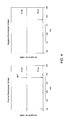
- FIG. 4 is a graph showing the output of the monitor wherein a sample of imipramine in methanol is introduced by the spray source at positive and negative voltage and observed with the lamp on and off;
- FIG. 5 is an illustration of a side view of the monitor shown in FIG. 3;
- FIG. 6 is an illustration of a syringe sample delivery system for the monitor
- FIG. 7 is an illustration of a side view of an alternate embodiment of the monitor.
- FIG. 8 is an illustration of a top view of the monitor shown in FIG. 7;
- FIG. 9 is a graph showing an output of a monitor that utilizes multiple light sources each photoionizing a sample at a different energy
- FIG. 10 are graphs showing an output of a monitor that utilizes a continuous photoionization source and a pulsed photoionization/dissociation source;
- FIG. 11 is an illustration of an alternate embodiment of the monitor
- FIG. 12 is an illustration of an alternate embodiment of the monitor.
- a monitor that can detect a trace molecule that is ionized at approximately one atmosphere.
- the molecule is ionized with a photoionizer and detected by a detector.
- the monitor may include a number of techniques to introduce a sample into the photbionizer at approximately one atmosphere.
- One technique includes creating an electrically charged spray that is directed into the ionizer.
- the photoionizer may include a plurality of light sources that each ionize the sample with a different radiation energy.
- FIG. 1 shows an embodiment of a monitor 10 of the present invention.
- the monitor 10 may include a photoionizer 12 that is coupled to a detector 14 .
- the detector 14 may be a mass detector.
- the photoionizer 12 may include an inlet 16 that allows a sample to flow into a ionization chamber 18 .
- a light source 20 may direct a beam of light into the chamber 18 to ionize one or more trace molecules in the sample.
- the light source 20 may emit light which has a wavelength so that photo-energy between 8.0 and 12.0 electron volts (eV) is delivered to the sample. Photo-energy between 8.0 and 12.0 is high enough to ionize most trace molecules without creating much molecular fragmentation within the sample.
- the light source may be a Nd:YAG laser which emits light at a wavelength of 355 nanometers (nm). The 355 nm light may travel through a frequency tripling cell that generates light at 118 nms. 118 nm light has an energy of 10.5 eV.
- a light source is described in U.S. Pat. No. 5,808,299 issued to Syage, which is hereby incorporated by reference.
- the light source may include continuous or pulsed discharge lamps which are disclosed in U.S. Pat. No. 3,933,432 issued to Driscoll; U.S. Pat. No. 5,393,979 issued to Hsi; U.S. Pat. No. 5,338,931 issued to Spangler et al.; and U.S. Pat. 5,206,594 issued to Zipf, which are-hereby incorporated by reference.
- the photoionizer 12 may have a first electrode 22 , a second electrode 24 and a third electrode 26 .
- the electrodes 22 , 24 and 26 may have voltage potentials that direct the ionized molecules through an aperture 28 in the third electrode 26 and into a chamber 30 .
- the chamber 30 may include an electrode 32 that has a voltage potential, that in combination with the electrodes 22 , 24 and 26 pull the ionized molecules through an aperture 34 in electrode 32 and into the detector 14 .
- the electrodes 22 , 24 , 26 and 32 may have voltage potentials of 50, 40, 20 and 10 volts, respectively.
- the chamber 30 may be coupled to a pump 36 .
- the intermediate chamber 30 and pump 36 can increase the throughput from the photoionizer 12 .
- the throughput from the photoionizer 12 in the monitor 10 of the present invention may be defined by the equation:
- P1 the pressure within the chamber 30 .
- S1 the pumping speed of the pump 36 .
- the throughput for a non-chamber system can be defined by the equation:
- UO2 the throughput from the photoionzier.
- P2 the pressure within the first region of the detector.
- S2 the pumping speed of the pump (not shown) coupled to the detector.
- the inclusion of the chamber 30 and pump 36 can increase the throughput UO 2 by 200 times.
- a gas throughput of UO 2 10 torr L/s is equivalent to a value of about 800 atm cm 3 /min. If the gas is a volatilized liquid such as methanol, then the liquid volume flow rate that can be sustained by the monitor 10 is about 1.6 ml/min. This calculation is based on 1 ml of liquid methanol volatilizing to about 500 cm 3 of vapor at about 200° C.
- the residence time of the sample within the chamber 18 can be defined by the equation:
- VO the volume of the chamber 18 .
- UO 1 is the throughput from the ionization chamber 18 into chamber 30 .
- U 12 is the throughput from the chamber 30 to the detector 14 .
- UO 2 is the throughput from the ionization chamber 18 to the detector 14 .
- FIG. 2 shows a fast response to a liquid sample injected into the chamber 18 .
- the actual response time of the monitor is actually limited by the injection time, and not the residence time within the ionization chamber 18 .
- FIGS. 3 and 4 show an embodiment of a photoionizer 100 that includes a inlet such as a liquid spray device 102 that can spray a sample into an ionization chamber 104 .
- the photoionizer 100 may include a pair of light sources 106 that are mounted to a mounting block 108 .
- the photoionizer 100 may have a first electrode 110 with an aperture 112 , a second electrode 114 with an aperture 116 , and a third electrode 118 with an aperture 120 .
- the electrodes 114 and 118 may have voltage potentials that guide ionized molecules out of the chamber 104 .
- the photoionizer 100 is coupled to a detector (not shown) and may include an intermediate pump 121 .
- the liquid spray device 102 may include a tube 122 within a tube 124 .
- the spray device 102 may be a nebulizer wherein the inner tube 122 contains a liquid sample and the outer tube 124 carries a gas flow that breaks the liquid into drops to create an aerosol that flows into the chamber 104 .
- the liquid spray device 102 can also be a capillary without the gas sheath flow.
- the diameters of the aperture 112 and 116 may be varied to adjust the pressure of the chamber 104 .
- the aperture 112 can be made relatively large to allow a significant amount or all of the spray to enter the chamber 104 . This mode may provide an ionization pressure of approximately 760 torr. This pressure can also be accomplished by placing the inner tube 122 within the aperture 112 . If the tube 122 is sealed, the chamber 104 can operate at pressures higher than 760 torr.
- the aperture 112 can lead to an enrichment of the desired higher molecular weight compounds in the liquid sample because solvent may evaporate off and the heavier compounds may stay on the spray centerline.
- the inner tube 122 can be constructed from metal and operated as an electrospray tip by applying a high voltage potential between the tube 122 and the electrode 110 .
- the electrospray source can be of the ion spray type as disclosed in U.S. Pat. No. 4,861,988 issued to Henion et al.
- the voltage potential may be set low enough to avoid forming significant ionization of desired compounds dissolved in solvent, but high enough to charge the liquid droplets so that the droplets accelerate and evaporate without thermal heating.
- the aerosol drops enter the ionization chamber 104 where the desired compounds are ionized in the gas phase or in the aerosol.
- the ionized molecules separate from the remaining aerosol under the influence of the voltage potentials of the electrodes 110 , 114 and 118 .
- the voltage on the tube 122 can be adjusted to positive voltage relative to the electrode skimmer 112 . Then positively charged aerosol droplets will be directed toward the ionizer region 104 . If the voltage is raised to sufficiently high values, then electrospray ionization will result and positively charged electrospray ions will be observed in the mass spectrum. To minimize detection of these positively charged electrospray ions, the tube 122 may have a voltage that is negative relative to electrode skimmer 112 . Then negatively charged aerosol droplets will be directed toward the ionizer region 104 . Photoionization in region 104 will generate positively charged ions without the presence of positively charged electrospray ions.
- FIG. 4 shows photoionization mass spectra of a standard solution of imipramine-d 6 in methanol showing the positive and negative spray tip modes for the photoionization lamp on and off.
- the photoionizer 100 can be operated in three different modes when the liquid spray is an electrospray device.
- the first mode is having ionization by both the liquid spray device 102 and the light sources 106 .
- the second mode may be ionization with only the liquid spray device 102 .
- the third mode may be ionization with only the light sources 106 . These modes may be rapidly switched.
- the photoionizer 100 can also have a discharge needle in region 104 in order to perform atmospheric pressure chemical ionization by prior art methods.
- This embodiment combined with photoionization gives a dual ionization capability that would make the ionization source applicable to a wider range of compounds.
- the photoionizer and the chemical ionizer may be operated independently or simultaneously.
- the photoionizer 100 may include a syringe port 126 that allows a liquid sample to be injected into the chamber 104 .
- FIG. 6 shows a specific embodiment of a syringe port 130 that has a pair of septa 132 and 134 .
- the syringe port 130 may have a pump-out port 136 that maintains a low pressure between the septa 132 and 134 .
- the syringe port 130 may also have a co-flow port 138 that introduces a flow of gas such as dry nitrogen, argon or helium, to smooth out the large pressure transient that occurs when a syringe is inserted through the septa 132 and 134 .
- a ball valve 140 may be utilized to close off the port 130 and allow replacement of the septa 132 and 134 .
- the syringe port 130 may have only one septum 132 or 134 .
- a voltage may be applied to the syringe needle so that it may operate as an electrospray source.
- the co-flow port 138 may be configured as a tube to provide a nebulizing sheath flow to the electrospray needle.
- FIGS. 7 and 8 show another embodiment of a photoionizer 200 wherein the entrance electrode 202 is located at an angle from the exit electrodes 204 and 206 .
- the photoionizer 200 may include a liquid spray device 208 that directs a sample into an ionization chamber 210 .
- the photoionizer may be coupled to a detector (not shown) and an intermediate pump 212 .
- the photoionizer 200 may include three separate light sources 214 , 216 and 218 mounted to a mounting block 220 . Additional light sources may increase the ion molecule yield from the sample.
- the light sources 214 , 216 and 218 may each have different radiation energies.
- light source 214 may be a Krypton (Kr) line source that emits light having energy of 10.0 eV
- the second light source 216 may be an Argon (Ar) source emitting light at an energy of 11.7 eV
- the third light source 218 may be a Xenon (Xe) light source emitting light at energy of 8.4 eV.
- one or more of the light sources 214 , 16 and 218 may be an Xe arc lamp. As shown in FIG. 9, molecules that have ionization potentials between the energies of the light sources will be ionized by the Kr light source, but not the Xe light source.
- Each light source 214 , 216 and/or 218 may emit a range of wavelengths at sufficient intensity to photodissociate the ions that are formed.
- a pulsed Xe arc lamp emits high energy-radiation for ionization and also lower energy radiation that can be photoabsorbed by the ions causing them to dissociate to fragments.
- Controlled photofragmentation can be used as a method to obtain structure information on the molecule and also to determine if an existing ion is a fragment or a parent ion
- FIG. 10 shows a photoionization mass spectrum of DIMP using a continuous wave Kr lamp and then with a pulsed Xe arc lamp.
- a molecular ion and a fragment ion are observed.
- the fragment ion is greatly enhanced.
- the different lamps can be rapidly switched giving real-time difference spectra information. Difference spectra can also be recorded by switching the photoionization and electrospray ionization methods as described before.
- the photoionizaton sources such as those in FIGS. 3 and 7 have an inlet port near the lamp surface to introduce an inert gas to sweep past the lamp surface. Referring to FIG. 3, the sweep gas would pass across the surface of the light source 106 in order to keep condensable compounds from adsorbing on the light source surface and to keep the density of solvent molecules near the light source low so that light is not significantly absorbed by the solvent.
- FIG. 11 shows another embodiment of a monitor 300 .
- the monitor 300 may have a pair of tubes 302 and 304 that introduce a sample to a chamber 306 .
- the monitor 300 may have electrodes 308 and 310 and a pump 312 to pull some of the molecules out of the chamber 306 .
- the monitor 300 includes a light source 314 and a light guide 316 that directs light to an area adjacent to the outlet of the tubes 302 and 304 .
- the light guide 316 may be an optical fiber or tappered hollow tube.
- a sweep gas may be introduced to the chamber to clean the light source 314 and light guide 316 and prevent high absorption by any solvent in the sample.
- FIG. 12 shows another embodiment of a monitor 300 ′ wherein the tubes 302 and 304 are located outside the chamber 306 .
- the monitor 300 ′ may have another electrode 318 that operates in the same manner as electrode 110 shown in FIG. 3 .
Abstract
Description
| TABLE I | ||||||
| Chamber | No- | |||||
| P1 |
| 1 | torr | N/ | |||
| P2 | |||||
| 10−3 | |
10−3 | torr | ||
| S1 | 10 | L/s | N/A | ||
| S2 | 50 | L/s | 50 | L/s | |
| |
10 | torr L/s | N/A | ||
| U12 | 0.05 | torr L/s | N/ | ||
| U02 | |||||
| 10 | torr L/s | 0.05 | torr L/ | ||
| V0 | |||||
| 1 | |
1 | mL | ||
| P0 | 100-760 | torr | 0.1-760 | torr | |
| T0 | 0.01-0.076 | s | 0.002-15.2 | s | |
Claims (30)
Priority Applications (9)
| Application Number | Priority Date | Filing Date | Title |
|---|---|---|---|
| US09/596,307 US6630664B1 (en) | 1999-02-09 | 2000-06-14 | Atmospheric pressure photoionizer for mass spectrometry |
| PCT/US2001/019140 WO2001097252A1 (en) | 2000-06-14 | 2001-06-14 | Atmospheric pressure photoionizer for mass spectrometry |
| CA2411532A CA2411532C (en) | 2000-06-14 | 2001-06-14 | Atmospheric pressure photoionizer for mass spectrometry |
| AU2001266925A AU2001266925A1 (en) | 2000-06-14 | 2001-06-14 | Atmospheric pressure photoionizer for mass spectrometry |
| EP01944520.4A EP1297554B1 (en) | 2000-06-14 | 2001-06-14 | Atmospheric pressure photoionizer for mass spectrometry |
| US10/334,506 US7119342B2 (en) | 1999-02-09 | 2002-12-31 | Interfaces for a photoionization mass spectrometer |
| US10/672,958 US7109476B2 (en) | 1999-02-09 | 2003-09-24 | Multiple ion sources involving atmospheric pressure photoionization |
| US11/004,495 US7161144B2 (en) | 1999-02-09 | 2004-12-03 | Interfaces for a photoionization mass spectrometer |
| US11/509,479 US20070138387A1 (en) | 1999-02-09 | 2006-08-23 | Interfaces for a photoionization mass spectrometer |
Applications Claiming Priority (2)
| Application Number | Priority Date | Filing Date | Title |
|---|---|---|---|
| US09/247,646 US6211516B1 (en) | 1999-02-09 | 1999-02-09 | Photoionization mass spectrometer |
| US09/596,307 US6630664B1 (en) | 1999-02-09 | 2000-06-14 | Atmospheric pressure photoionizer for mass spectrometry |
Related Parent Applications (1)
| Application Number | Title | Priority Date | Filing Date |
|---|---|---|---|
| US09/247,646 Continuation-In-Part US6211516B1 (en) | 1999-02-09 | 1999-02-09 | Photoionization mass spectrometer |
Related Child Applications (3)
| Application Number | Title | Priority Date | Filing Date |
|---|---|---|---|
| US10/334,506 Continuation-In-Part US7119342B2 (en) | 1999-02-09 | 2002-12-31 | Interfaces for a photoionization mass spectrometer |
| US10/672,958 Continuation-In-Part US7109476B2 (en) | 1999-02-09 | 2003-09-24 | Multiple ion sources involving atmospheric pressure photoionization |
| US11/004,495 Continuation-In-Part US7161144B2 (en) | 1999-02-09 | 2004-12-03 | Interfaces for a photoionization mass spectrometer |
Publications (1)
| Publication Number | Publication Date |
|---|---|
| US6630664B1 true US6630664B1 (en) | 2003-10-07 |
Family
ID=24386802
Family Applications (1)
| Application Number | Title | Priority Date | Filing Date |
|---|---|---|---|
| US09/596,307 Expired - Lifetime US6630664B1 (en) | 1999-02-09 | 2000-06-14 | Atmospheric pressure photoionizer for mass spectrometry |
Country Status (5)
| Country | Link |
|---|---|
| US (1) | US6630664B1 (en) |
| EP (1) | EP1297554B1 (en) |
| AU (1) | AU2001266925A1 (en) |
| CA (1) | CA2411532C (en) |
| WO (1) | WO2001097252A1 (en) |
Cited By (31)
| Publication number | Priority date | Publication date | Assignee | Title |
|---|---|---|---|---|
| US20040108857A1 (en) * | 2002-07-23 | 2004-06-10 | Paul Jarski | Ionization detectors |
| US20040256550A1 (en) * | 2003-01-27 | 2004-12-23 | Finch Jeffrey W. | Coaxial atmospheric pressure photoionization source for mass spectrometers |
| WO2005050159A2 (en) * | 2003-10-14 | 2005-06-02 | Washington State University Research Foundation | Ion mobility spectrometry method and apparatus |
| US20050258360A1 (en) * | 2004-05-21 | 2005-11-24 | Whitehouse Craig M | Charged droplet sprayers |
| US20060054807A1 (en) * | 2004-09-15 | 2006-03-16 | Phytronix Technologies, Inc. | Ionization source for mass spectrometer |
| US20070023675A1 (en) * | 2002-09-18 | 2007-02-01 | Fischer Steven M | Multimode ionization source |
| US20080047330A1 (en) * | 2006-08-25 | 2008-02-28 | Whitehouse Craig M | Sample component trapping, release, and separation with membrane assemblies interfaced to electrospray mass spectrometry |
| US20090101814A1 (en) * | 2007-10-18 | 2009-04-23 | Aviv Amirav | Capillary separated vaporization chamber and nozzle device and method |
| US20100019141A1 (en) * | 2008-07-25 | 2010-01-28 | Varian Semiconductor Equipment Associates, Inc. | Energy contamination monitor with neutral current detection |
| US20100154568A1 (en) * | 2008-11-19 | 2010-06-24 | Roth Michael J | Analytical Instruments, Assemblies, and Methods |
| WO2011127130A1 (en) * | 2010-04-09 | 2011-10-13 | Water Technologies Corporation | Apparatus for photoionization of an analyte in an eluent of a chromatography column |
| DE102012209324A1 (en) * | 2012-06-01 | 2013-12-05 | Helmholtz Zentrum München | Optical fiber device for an ionization device and method for ionizing atoms and / or molecules |
| US8723111B2 (en) | 2011-09-29 | 2014-05-13 | Morpho Detection, Llc | Apparatus for chemical sampling and method of assembling the same |
| USRE44887E1 (en) | 2005-05-19 | 2014-05-13 | Perkinelmer Health Sciences, Inc. | Sample component trapping, release, and separation with membrane assemblies interfaced to electrospray mass spectrometry |
| US20140217281A1 (en) * | 2013-02-01 | 2014-08-07 | The Rockefeller University | Method and apparatus for improving ion transmission into a mass spectrometer |
| US20140374583A1 (en) * | 2013-06-24 | 2014-12-25 | Agilent Technologies, Inc. | Electron ionization (ei) utilizing different ei energies |
| EP3073511A1 (en) * | 2015-03-24 | 2016-09-28 | Morpho Detection, LLC | System and method for trace detection using dual ionization sources |
| US20180151341A1 (en) * | 2015-05-05 | 2018-05-31 | Fraunhofer-Gesellschaft zur Förderung der angewandten Forschung e.V. | Online mass spectrometer for real-time detection of volatile components from the gas and liquid phase for process analysis |
| US20180166269A1 (en) * | 2016-12-13 | 2018-06-14 | R.J. Reynolds Tobacco Company | Real time measurement techniques combining light sources and mass spectrometer |
| US10049868B2 (en) | 2016-12-06 | 2018-08-14 | Rapiscan Systems, Inc. | Apparatus for detecting constituents in a sample and method of using the same |
| US10176977B2 (en) | 2014-12-12 | 2019-01-08 | Agilent Technologies, Inc. | Ion source for soft electron ionization and related systems and methods |
| US10317387B2 (en) | 2016-03-08 | 2019-06-11 | Rapiscan Systems, Inc. | Chemical vaporization and detection of compounds having low volatility |
| US10345282B2 (en) | 2016-03-08 | 2019-07-09 | Rapiscan Systems, Inc. | Temperature influenced chemical vaporization and detection of compounds having low volatility |
| US10361074B2 (en) | 2016-12-28 | 2019-07-23 | Rapiscan Systems, Inc. | Ionization chamber having a potential-well for ion trapping and ion compression |
| US10386340B2 (en) | 2016-03-31 | 2019-08-20 | Rapiscan Systems, Inc. | Detection of substances of interest using gas-solid phase chemistry |
| US10458885B2 (en) | 2017-03-31 | 2019-10-29 | Rapiscan Systems, Inc. | Rapid desorber heating and cooling for trace detection |
| US20190348269A1 (en) * | 2018-05-13 | 2019-11-14 | Aviv Amirav | Mass Spectrometer with Photoionization Ion Source Method and System |
| US10665446B2 (en) | 2018-01-24 | 2020-05-26 | Rapiscan Systems, Inc. | Surface layer disruption and ionization utilizing an extreme ultraviolet radiation source |
| US10707063B2 (en) | 2016-12-22 | 2020-07-07 | Rapiscan Systems, Inc. | Systems and methods for calibration, verification, and sensitivity checks for detectors |
| US11235329B2 (en) | 2017-08-10 | 2022-02-01 | Rapiscan Systems, Inc. | Systems and methods for substance detection using thermally stable collection devices |
| US11609214B2 (en) | 2019-07-31 | 2023-03-21 | Rapiscan Systems, Inc. | Systems and methods for improving detection accuracy in electronic trace detectors |
Families Citing this family (3)
| Publication number | Priority date | Publication date | Assignee | Title |
|---|---|---|---|---|
| US7109476B2 (en) * | 1999-02-09 | 2006-09-19 | Syagen Technology | Multiple ion sources involving atmospheric pressure photoionization |
| US6646257B1 (en) * | 2002-09-18 | 2003-11-11 | Agilent Technologies, Inc. | Multimode ionization source |
| JP6181764B2 (en) * | 2013-09-05 | 2017-08-16 | 株式会社日立ハイテクノロジーズ | Hybrid ion source and mass spectrometer |
Citations (43)
| Publication number | Priority date | Publication date | Assignee | Title |
|---|---|---|---|---|
| US3555272A (en) | 1968-03-14 | 1971-01-12 | Exxon Research Engineering Co | Process for chemical ionization for intended use in mass spectrometry and the like |
| US4239967A (en) * | 1979-04-13 | 1980-12-16 | International Business Machines Corporation | Trace water measurement |
| US4365157A (en) | 1978-10-09 | 1982-12-21 | Gesellschaft Fur Strahlen-Und Umweltforschung Mbh | Fluid analyzer utilizing a laser beam |
| US4433241A (en) * | 1979-10-19 | 1984-02-21 | Ulrich Boesl | Process and apparatus for determining molecule spectra |
| US4531056A (en) * | 1983-04-20 | 1985-07-23 | Yale University | Method and apparatus for the mass spectrometric analysis of solutions |
| US4540884A (en) | 1982-12-29 | 1985-09-10 | Finnigan Corporation | Method of mass analyzing a sample by use of a quadrupole ion trap |
| US4733073A (en) | 1983-12-23 | 1988-03-22 | Sri International | Method and apparatus for surface diagnostics |
| US4780608A (en) | 1987-08-24 | 1988-10-25 | The United States Of America As Represented By The United States Department Of Energy | Laser sustained discharge nozzle apparatus for the production of an intense beam of high kinetic energy atomic species |
| US4804846A (en) * | 1987-12-04 | 1989-02-14 | O. I. Corporation | Photoionization detector for gas chromatography |
| US4849628A (en) | 1987-05-29 | 1989-07-18 | Martin Marietta Energy Systems, Inc. | Atmospheric sampling glow discharge ionization source |
| US4855594A (en) | 1988-03-02 | 1989-08-08 | Air Products And Chemicals, Inc. | Apparatus and process for improved detection limits in mass spectrometry |
| US4861988A (en) | 1987-09-30 | 1989-08-29 | Cornell Research Foundation, Inc. | Ion spray apparatus and method |
| US4931640A (en) | 1989-05-19 | 1990-06-05 | Marshall Alan G | Mass spectrometer with reduced static electric field |
| US4982097A (en) * | 1989-05-19 | 1991-01-01 | Battelle Memorial Institute | Vaporization device for continuous introduction of liquids into a mass spectrometer |
| US5032721A (en) | 1990-06-01 | 1991-07-16 | Environmental Technologies Group, Inc. | Acid gas monitor based on ion mobility spectrometry |
| US5070240A (en) * | 1990-08-29 | 1991-12-03 | Brigham Young University | Apparatus and methods for trace component analysis |
| US5153672A (en) * | 1989-04-14 | 1992-10-06 | The United States Of America As Represented By The United States Department Of Energy | High bandwidth vapor density diagnostic system |
| US5206594A (en) | 1990-05-11 | 1993-04-27 | Mine Safety Appliances Company | Apparatus and process for improved photoionization and detection |
| US5234838A (en) | 1990-04-17 | 1993-08-10 | Environmental Technologies Group, Inc. | Ammonia monitor based on ion mobility spectrometry with selective dopant chemistry |
| US5283436A (en) | 1990-01-08 | 1994-02-01 | Bruker-Franzen Analytik Gmbh | Generation of an exact three-dimensional quadrupole electric field and superposition of a homogeneous electric field in trapping-exciting mass spectrometer (TEMS) |
| US5294797A (en) | 1991-03-13 | 1994-03-15 | Bruker-Franzen Analytik Gmbh | Method and apparatus for generating ions from thermally unstable, non-volatile, large molecules, particularly for a mass spectrometer such as a time-of-flight mass spectrometer |
| US5311016A (en) | 1992-08-21 | 1994-05-10 | The United States Of America As Represented By The United State Department Of Energy | Apparatus for preparing a sample for mass spectrometry |
| US5338931A (en) * | 1992-04-23 | 1994-08-16 | Environmental Technologies Group, Inc. | Photoionization ion mobility spectrometer |
| US5343488A (en) * | 1991-10-18 | 1994-08-30 | Commissariat A L'energie Atomique | Installation for the formation of a laser beam suitable for isotope separation |
| US5381006A (en) | 1992-05-29 | 1995-01-10 | Varian Associates, Inc. | Methods of using ion trap mass spectrometers |
| US5393979A (en) | 1993-05-12 | 1995-02-28 | Rae Systems, Inc. | Photo-ionization detector for detecting volatile organic gases |
| US5397895A (en) | 1992-09-24 | 1995-03-14 | The United States Of America As Represented By The Secretary Of Commerce | Photoionization mass spectroscopy flux monitor |
| US5412207A (en) | 1993-10-07 | 1995-05-02 | Marquette Electronics, Inc. | Method and apparatus for analyzing a gas sample |
| US5469323A (en) | 1991-03-26 | 1995-11-21 | Agency Of Industrial Science And Technology | Method and apparatus for trapping charged particles |
| US5504328A (en) | 1994-12-09 | 1996-04-02 | Sematech, Inc. | Endpoint detection utilizing ultraviolet mass spectrometry |
| US5527731A (en) | 1992-11-13 | 1996-06-18 | Hitachi, Ltd. | Surface treating method and apparatus therefor |
| US5554846A (en) | 1995-07-31 | 1996-09-10 | Environmental Technologies Group, Inc. | Apparatus and a method for detecting alarm molecules in an air sample |
| US5569917A (en) | 1995-05-19 | 1996-10-29 | Varian Associates, Inc. | Apparatus for and method of forming a parallel ion beam |
| US5631462A (en) | 1995-01-17 | 1997-05-20 | Lucent Technologies Inc. | Laser-assisted particle analysis |
| US5808299A (en) | 1996-04-01 | 1998-09-15 | Syagen Technology | Real-time multispecies monitoring by photoionization mass spectrometry |
| US5826214A (en) * | 1996-09-26 | 1998-10-20 | The United States Of America As Represented By The Secretary Of The Army | Hand-held probe for real-time analysis of trace pollutants in atmosphere and on surfaces |
| US5854431A (en) | 1997-12-10 | 1998-12-29 | Sandia Corporation | Particle preconcentrator |
| US5869832A (en) | 1997-10-14 | 1999-02-09 | University Of Washington | Device and method for forming ions |
| US5906946A (en) * | 1996-08-05 | 1999-05-25 | United States Of America As Represented By The Secretary Of The Army | Device and process for detecting and discriminating NO and NO2 from other nitrocompounds in real-time and in situ |
| US6011259A (en) | 1995-08-10 | 2000-01-04 | Analytica Of Branford, Inc. | Multipole ion guide ion trap mass spectrometry with MS/MSN analysis |
| US6040575A (en) | 1998-01-23 | 2000-03-21 | Analytica Of Branford, Inc. | Mass spectrometry from surfaces |
| US6140638A (en) | 1997-06-04 | 2000-10-31 | Mds Inc. | Bandpass reactive collision cell |
| WO2001033605A2 (en) * | 1999-10-29 | 2001-05-10 | Rijksuniversiteit Groningen | Atmospheric pressure photoionization (appi): a new ionization method for liquid chromatography-mass spectrometry |
Family Cites Families (3)
| Publication number | Priority date | Publication date | Assignee | Title |
|---|---|---|---|---|
| WO1999001889A1 (en) * | 1997-07-02 | 1999-01-14 | Merck & Co., Inc. | Novel mass spectrometer |
| US6054709A (en) * | 1997-12-05 | 2000-04-25 | The University Of British Columbia | Method and apparatus for determining the rates of reactions in liquids by mass spectrometry |
| US6211516B1 (en) * | 1999-02-09 | 2001-04-03 | Syagen Technology | Photoionization mass spectrometer |
-
2000
- 2000-06-14 US US09/596,307 patent/US6630664B1/en not_active Expired - Lifetime
-
2001
- 2001-06-14 EP EP01944520.4A patent/EP1297554B1/en not_active Expired - Lifetime
- 2001-06-14 WO PCT/US2001/019140 patent/WO2001097252A1/en active Application Filing
- 2001-06-14 AU AU2001266925A patent/AU2001266925A1/en not_active Abandoned
- 2001-06-14 CA CA2411532A patent/CA2411532C/en not_active Expired - Fee Related
Patent Citations (44)
| Publication number | Priority date | Publication date | Assignee | Title |
|---|---|---|---|---|
| US3555272A (en) | 1968-03-14 | 1971-01-12 | Exxon Research Engineering Co | Process for chemical ionization for intended use in mass spectrometry and the like |
| US4365157A (en) | 1978-10-09 | 1982-12-21 | Gesellschaft Fur Strahlen-Und Umweltforschung Mbh | Fluid analyzer utilizing a laser beam |
| US4239967A (en) * | 1979-04-13 | 1980-12-16 | International Business Machines Corporation | Trace water measurement |
| US4433241A (en) * | 1979-10-19 | 1984-02-21 | Ulrich Boesl | Process and apparatus for determining molecule spectra |
| US4540884A (en) | 1982-12-29 | 1985-09-10 | Finnigan Corporation | Method of mass analyzing a sample by use of a quadrupole ion trap |
| US4531056A (en) * | 1983-04-20 | 1985-07-23 | Yale University | Method and apparatus for the mass spectrometric analysis of solutions |
| US4733073A (en) | 1983-12-23 | 1988-03-22 | Sri International | Method and apparatus for surface diagnostics |
| US4849628A (en) | 1987-05-29 | 1989-07-18 | Martin Marietta Energy Systems, Inc. | Atmospheric sampling glow discharge ionization source |
| US4780608A (en) | 1987-08-24 | 1988-10-25 | The United States Of America As Represented By The United States Department Of Energy | Laser sustained discharge nozzle apparatus for the production of an intense beam of high kinetic energy atomic species |
| US4861988A (en) | 1987-09-30 | 1989-08-29 | Cornell Research Foundation, Inc. | Ion spray apparatus and method |
| US4804846A (en) * | 1987-12-04 | 1989-02-14 | O. I. Corporation | Photoionization detector for gas chromatography |
| US4855594A (en) | 1988-03-02 | 1989-08-08 | Air Products And Chemicals, Inc. | Apparatus and process for improved detection limits in mass spectrometry |
| US5153672A (en) * | 1989-04-14 | 1992-10-06 | The United States Of America As Represented By The United States Department Of Energy | High bandwidth vapor density diagnostic system |
| US4931640A (en) | 1989-05-19 | 1990-06-05 | Marshall Alan G | Mass spectrometer with reduced static electric field |
| US4982097A (en) * | 1989-05-19 | 1991-01-01 | Battelle Memorial Institute | Vaporization device for continuous introduction of liquids into a mass spectrometer |
| US5283436A (en) | 1990-01-08 | 1994-02-01 | Bruker-Franzen Analytik Gmbh | Generation of an exact three-dimensional quadrupole electric field and superposition of a homogeneous electric field in trapping-exciting mass spectrometer (TEMS) |
| US5234838A (en) | 1990-04-17 | 1993-08-10 | Environmental Technologies Group, Inc. | Ammonia monitor based on ion mobility spectrometry with selective dopant chemistry |
| US5206594A (en) | 1990-05-11 | 1993-04-27 | Mine Safety Appliances Company | Apparatus and process for improved photoionization and detection |
| US5032721A (en) | 1990-06-01 | 1991-07-16 | Environmental Technologies Group, Inc. | Acid gas monitor based on ion mobility spectrometry |
| US5070240A (en) * | 1990-08-29 | 1991-12-03 | Brigham Young University | Apparatus and methods for trace component analysis |
| US5070240B1 (en) * | 1990-08-29 | 1996-09-10 | Univ Brigham Young | Apparatus and methods for trace component analysis |
| US5294797A (en) | 1991-03-13 | 1994-03-15 | Bruker-Franzen Analytik Gmbh | Method and apparatus for generating ions from thermally unstable, non-volatile, large molecules, particularly for a mass spectrometer such as a time-of-flight mass spectrometer |
| US5469323A (en) | 1991-03-26 | 1995-11-21 | Agency Of Industrial Science And Technology | Method and apparatus for trapping charged particles |
| US5343488A (en) * | 1991-10-18 | 1994-08-30 | Commissariat A L'energie Atomique | Installation for the formation of a laser beam suitable for isotope separation |
| US5338931A (en) * | 1992-04-23 | 1994-08-16 | Environmental Technologies Group, Inc. | Photoionization ion mobility spectrometer |
| US5381006A (en) | 1992-05-29 | 1995-01-10 | Varian Associates, Inc. | Methods of using ion trap mass spectrometers |
| US5311016A (en) | 1992-08-21 | 1994-05-10 | The United States Of America As Represented By The United State Department Of Energy | Apparatus for preparing a sample for mass spectrometry |
| US5397895A (en) | 1992-09-24 | 1995-03-14 | The United States Of America As Represented By The Secretary Of Commerce | Photoionization mass spectroscopy flux monitor |
| US5527731A (en) | 1992-11-13 | 1996-06-18 | Hitachi, Ltd. | Surface treating method and apparatus therefor |
| US5393979A (en) | 1993-05-12 | 1995-02-28 | Rae Systems, Inc. | Photo-ionization detector for detecting volatile organic gases |
| US5412207A (en) | 1993-10-07 | 1995-05-02 | Marquette Electronics, Inc. | Method and apparatus for analyzing a gas sample |
| US5504328A (en) | 1994-12-09 | 1996-04-02 | Sematech, Inc. | Endpoint detection utilizing ultraviolet mass spectrometry |
| US5631462A (en) | 1995-01-17 | 1997-05-20 | Lucent Technologies Inc. | Laser-assisted particle analysis |
| US5569917A (en) | 1995-05-19 | 1996-10-29 | Varian Associates, Inc. | Apparatus for and method of forming a parallel ion beam |
| US5554846A (en) | 1995-07-31 | 1996-09-10 | Environmental Technologies Group, Inc. | Apparatus and a method for detecting alarm molecules in an air sample |
| US6011259A (en) | 1995-08-10 | 2000-01-04 | Analytica Of Branford, Inc. | Multipole ion guide ion trap mass spectrometry with MS/MSN analysis |
| US5808299A (en) | 1996-04-01 | 1998-09-15 | Syagen Technology | Real-time multispecies monitoring by photoionization mass spectrometry |
| US5906946A (en) * | 1996-08-05 | 1999-05-25 | United States Of America As Represented By The Secretary Of The Army | Device and process for detecting and discriminating NO and NO2 from other nitrocompounds in real-time and in situ |
| US5826214A (en) * | 1996-09-26 | 1998-10-20 | The United States Of America As Represented By The Secretary Of The Army | Hand-held probe for real-time analysis of trace pollutants in atmosphere and on surfaces |
| US6140638A (en) | 1997-06-04 | 2000-10-31 | Mds Inc. | Bandpass reactive collision cell |
| US5869832A (en) | 1997-10-14 | 1999-02-09 | University Of Washington | Device and method for forming ions |
| US5854431A (en) | 1997-12-10 | 1998-12-29 | Sandia Corporation | Particle preconcentrator |
| US6040575A (en) | 1998-01-23 | 2000-03-21 | Analytica Of Branford, Inc. | Mass spectrometry from surfaces |
| WO2001033605A2 (en) * | 1999-10-29 | 2001-05-10 | Rijksuniversiteit Groningen | Atmospheric pressure photoionization (appi): a new ionization method for liquid chromatography-mass spectrometry |
Non-Patent Citations (18)
| Title |
|---|
| "A Hybrid Instrument that Combines TOF With the Ion Trap Yields Excellent Sensitivity for Small Samples," Anal. Chem. vol. 67, No. 7, Apr. 1, 1995. |
| "An Ion Trap Storage/Time-of-Flight Mass Spectrometer," S.M. Michael et al., Rev. Sci. Instrum. 63 (10), Oct. 1992, pp. 4277-4284. |
| "Compact Vacuum Ultraviolet Source for Photoelectron Spectroscopy," Rev. Sci. Instrum. 60(7), Jul. 1989. |
| "Cyclic Ketone Mixture Analysis Using 2 + 1 Resonance-Enhanced Multiphoton Ionization Mass Spectrometry, " Dale R. Nesselrodt et al., Anal. Chem. 1994, 66, 2497-2504. |
| "Generation of Narrowband Tunable VUV Radiation at the Lyman-a Wavelength," Optics Communications, vol. 33, No. 1, Apr. 1980. |
| "New Developments in Molecular Detection by Supersonic Moecular Beam, Laser Mass Spectrometry," Jack A. Syage, pp. 469-489. |
| "Pulsed Laser Desorption of Biological Molecules in Supersonic Beam Mass Spectrometry W/Resonant Two-Photon Ionization Detection," R. Tembreull, Anal. Chem. 1987, 59, 1082-1088. |
| "Real-Time Detection of Chemical Agents Using Molecular Beam Laser Mass Spectrometry," Jack A. Syage, Aerophysics Laboratory, Reprinted from Analytical Chemistry, 1990, 62. |
| "Third-Harmonic Generation in Argon, Krypton, & Xenon: Bandwidth Limitations in the Vicinity of Lyman-a," R. Mahon IEEE Journal of Quantum Electronics, vol. QE-15, No. 6, 6/79. |
| "Tunable VUV Radiation Generated by Two-Photon Resonant Frequency Mixing in Zenon," IEEE Journal of Quantum Electronics, vol. QE-19, No. 2, Feb. 1983. |
| E.R. Rohwer, R.C. Beavis,C. Koster, J. Lindner, J. Grotemeyer and E.W. Schlag, "Fast Pulsed Laser Induced Electron Generation for Electron Impact Mass Spectrometry", Nov. 23, 1988, pp. 1151-1153. |
| J.G. Boyle, L.D. Pfefferle, E.E. Gulcicek, S.D. Colson, "Laser-driven Electron Ionization for a VUV Photoionization Time-Of-Flight Mass Spectrometer", (11) pp.; American Institute of Physics. |
| P.Y. Cheng and H.L. Dai, "A Photoemitted Electron-Impact Ionization Method For Time-Of-Flight Mass Spectrometers", pp. 2211-2214, American Institute of Physics. |
| Pulsed Free Jets: Novel Nonlinear Media for Generation of Vacuum Ultraviolet and Extreme Ultraviolet Radiation,: J. Phys. Chem. 1984, 88,4459-4465. |
| R. Frey, et al. "Real-Time Vehicle Exhaust Analysis Using a Laser TOF Mass Spectrometer" Proc. 40t<h >Anal. Conf. Mass Spectrom & Allied Topics, 1992, pp 678-679. |
| R. Frey, et al. "Real-Time Vehicle Exhaust Analysis Using a Laser TOF Mass Spectrometer" Proc. 40th Anal. Conf. Mass Spectrom & Allied Topics, 1992, pp 678-679. |
| Revel'skii et al., Mass Spectrometry With Photoionization at Atmospheric Pressure and the Analysis of Multicomponent Mixtures Without Separation, Chemical and Physicochemical Methods of Analysis, 1991, Plenum Publishing Corporation, pp. 243-248.* * |
| U. Boesl et al. "Laser Ion Sources For Time-Of-Flight Mass Spectrometry", Int. J. Mass Spectrom. Ion Processes 131 (1994) 87-124. |
Cited By (56)
| Publication number | Priority date | Publication date | Assignee | Title |
|---|---|---|---|---|
| US20040108857A1 (en) * | 2002-07-23 | 2004-06-10 | Paul Jarski | Ionization detectors |
| US7488953B2 (en) * | 2002-09-18 | 2009-02-10 | Agilent Technologies, Inc. | Multimode ionization source |
| US20070023675A1 (en) * | 2002-09-18 | 2007-02-01 | Fischer Steven M | Multimode ionization source |
| US20040256550A1 (en) * | 2003-01-27 | 2004-12-23 | Finch Jeffrey W. | Coaxial atmospheric pressure photoionization source for mass spectrometers |
| WO2005050159A2 (en) * | 2003-10-14 | 2005-06-02 | Washington State University Research Foundation | Ion mobility spectrometry method and apparatus |
| US7777180B2 (en) | 2003-10-14 | 2010-08-17 | Washington State University Research Foundation | Ion mobility spectrometry method and apparatus |
| US20060186333A1 (en) * | 2003-10-14 | 2006-08-24 | Washington State University Research Foundation | Ion Mobility Spectrometry Method and Apparatus |
| WO2005050159A3 (en) * | 2003-10-14 | 2007-03-01 | Univ Washington | Ion mobility spectrometry method and apparatus |
| US20090078861A1 (en) * | 2003-10-14 | 2009-03-26 | Hill Jr Herbert Henderson | Ion Mobility Spectrometry Method and Apparatus |
| US7414242B2 (en) | 2003-10-14 | 2008-08-19 | Washington State University Research Foundation | Ion mobility spectrometry method and apparatus |
| US20050258360A1 (en) * | 2004-05-21 | 2005-11-24 | Whitehouse Craig M | Charged droplet sprayers |
| US7232992B2 (en) * | 2004-05-21 | 2007-06-19 | Analytica Of Branford, Inc. | Charged droplet sprayers |
| US7582863B2 (en) | 2004-09-15 | 2009-09-01 | Phytronix Technologies, Inc. | Sample support for desorption |
| US7321116B2 (en) | 2004-09-15 | 2008-01-22 | Phytronix Technologies, Inc. | Ionization source for mass spectrometer |
| US20060054807A1 (en) * | 2004-09-15 | 2006-03-16 | Phytronix Technologies, Inc. | Ionization source for mass spectrometer |
| US9302225B2 (en) | 2005-05-19 | 2016-04-05 | Perkinelmer Health Sciences, Inc. | Sample component trapping, release, and separation with membrane assemblies interfaced to electrospray mass spectrometry |
| US8455817B2 (en) | 2005-05-19 | 2013-06-04 | Perkinelmer Health Sciences, Inc. | Sample component trapping, release, and separation with membrane assemblies interfaced to electrospray mass spectrometry |
| USRE44887E1 (en) | 2005-05-19 | 2014-05-13 | Perkinelmer Health Sciences, Inc. | Sample component trapping, release, and separation with membrane assemblies interfaced to electrospray mass spectrometry |
| US20110220789A1 (en) * | 2005-05-19 | 2011-09-15 | Perkinelmer Health Sciences, Inc. | Sample Component Trapping, Release, and Separation with Membrane Assemblies Interfaced to Electrospray Mass Spectrometry |
| US8487243B2 (en) | 2005-05-19 | 2013-07-16 | Perkinelmer Health Sciences, Inc. | Sample component trapping, release, and separation with membrane assemblies interfaced to electrospray mass spectrometry |
| US20080047330A1 (en) * | 2006-08-25 | 2008-02-28 | Whitehouse Craig M | Sample component trapping, release, and separation with membrane assemblies interfaced to electrospray mass spectrometry |
| US20090101814A1 (en) * | 2007-10-18 | 2009-04-23 | Aviv Amirav | Capillary separated vaporization chamber and nozzle device and method |
| US8604424B2 (en) * | 2007-10-18 | 2013-12-10 | Aviv Amirav | Capillary separated vaporization chamber and nozzle device and method |
| US20100019141A1 (en) * | 2008-07-25 | 2010-01-28 | Varian Semiconductor Equipment Associates, Inc. | Energy contamination monitor with neutral current detection |
| US20100154568A1 (en) * | 2008-11-19 | 2010-06-24 | Roth Michael J | Analytical Instruments, Assemblies, and Methods |
| US20130020483A1 (en) * | 2010-04-09 | 2013-01-24 | Waters Technologies Corporation | Apparatus for photoionization of an analyte in an eluent of a chromatography column |
| WO2011127130A1 (en) * | 2010-04-09 | 2011-10-13 | Water Technologies Corporation | Apparatus for photoionization of an analyte in an eluent of a chromatography column |
| US8723111B2 (en) | 2011-09-29 | 2014-05-13 | Morpho Detection, Llc | Apparatus for chemical sampling and method of assembling the same |
| DE102012209324A1 (en) * | 2012-06-01 | 2013-12-05 | Helmholtz Zentrum München | Optical fiber device for an ionization device and method for ionizing atoms and / or molecules |
| US20140217281A1 (en) * | 2013-02-01 | 2014-08-07 | The Rockefeller University | Method and apparatus for improving ion transmission into a mass spectrometer |
| US9048079B2 (en) * | 2013-02-01 | 2015-06-02 | The Rockefeller University | Method and apparatus for improving ion transmission into a mass spectrometer |
| US9240310B2 (en) * | 2013-02-01 | 2016-01-19 | The Rockefeller University | Method and apparatus for improving ion transmission into a mass spectrometer |
| US20140374583A1 (en) * | 2013-06-24 | 2014-12-25 | Agilent Technologies, Inc. | Electron ionization (ei) utilizing different ei energies |
| US10176977B2 (en) | 2014-12-12 | 2019-01-08 | Agilent Technologies, Inc. | Ion source for soft electron ionization and related systems and methods |
| US9952179B2 (en) * | 2015-03-24 | 2018-04-24 | Rapiscan Systems, Inc. | System and method for trace detection using dual ionization sources |
| US20160282304A1 (en) * | 2015-03-24 | 2016-09-29 | Morpho Detection, Llc | System and method for trace detection using dual ionization sources |
| US20170191962A9 (en) * | 2015-03-24 | 2017-07-06 | Morpho Detection, Llc | System and method for trace detection using dual ionization sources |
| US20180284066A1 (en) * | 2015-03-24 | 2018-10-04 | Rapiscan Systems, Inc. | System and method for trace detection using dual ionization sources |
| EP3073511A1 (en) * | 2015-03-24 | 2016-09-28 | Morpho Detection, LLC | System and method for trace detection using dual ionization sources |
| US20180151341A1 (en) * | 2015-05-05 | 2018-05-31 | Fraunhofer-Gesellschaft zur Förderung der angewandten Forschung e.V. | Online mass spectrometer for real-time detection of volatile components from the gas and liquid phase for process analysis |
| US10361072B2 (en) * | 2015-05-05 | 2019-07-23 | Fraunhofer-Gesellschaft zur Förderung der angewandten Forschung e.V. | Online mass spectrometer for real-time detection of volatile components from the gas and liquid phase for process analysis |
| US10345282B2 (en) | 2016-03-08 | 2019-07-09 | Rapiscan Systems, Inc. | Temperature influenced chemical vaporization and detection of compounds having low volatility |
| US10317387B2 (en) | 2016-03-08 | 2019-06-11 | Rapiscan Systems, Inc. | Chemical vaporization and detection of compounds having low volatility |
| US10386340B2 (en) | 2016-03-31 | 2019-08-20 | Rapiscan Systems, Inc. | Detection of substances of interest using gas-solid phase chemistry |
| US10651024B2 (en) | 2016-12-06 | 2020-05-12 | Rapiscan Systems, Inc. | Apparatus for detecting constituents in a sample and method of using the same |
| US10049868B2 (en) | 2016-12-06 | 2018-08-14 | Rapiscan Systems, Inc. | Apparatus for detecting constituents in a sample and method of using the same |
| US10090143B2 (en) * | 2016-12-13 | 2018-10-02 | R.J. Reynolds Tobacco Company | Real time measurement techniques combining light sources and mass spectrometer |
| US20180166269A1 (en) * | 2016-12-13 | 2018-06-14 | R.J. Reynolds Tobacco Company | Real time measurement techniques combining light sources and mass spectrometer |
| US10707063B2 (en) | 2016-12-22 | 2020-07-07 | Rapiscan Systems, Inc. | Systems and methods for calibration, verification, and sensitivity checks for detectors |
| US10361074B2 (en) | 2016-12-28 | 2019-07-23 | Rapiscan Systems, Inc. | Ionization chamber having a potential-well for ion trapping and ion compression |
| US10458885B2 (en) | 2017-03-31 | 2019-10-29 | Rapiscan Systems, Inc. | Rapid desorber heating and cooling for trace detection |
| US11235329B2 (en) | 2017-08-10 | 2022-02-01 | Rapiscan Systems, Inc. | Systems and methods for substance detection using thermally stable collection devices |
| US10665446B2 (en) | 2018-01-24 | 2020-05-26 | Rapiscan Systems, Inc. | Surface layer disruption and ionization utilizing an extreme ultraviolet radiation source |
| US20190348269A1 (en) * | 2018-05-13 | 2019-11-14 | Aviv Amirav | Mass Spectrometer with Photoionization Ion Source Method and System |
| US10790131B2 (en) * | 2018-05-13 | 2020-09-29 | Aviv Amirav | Mass spectrometer with photoionization ion source method and system |
| US11609214B2 (en) | 2019-07-31 | 2023-03-21 | Rapiscan Systems, Inc. | Systems and methods for improving detection accuracy in electronic trace detectors |
Also Published As
| Publication number | Publication date |
|---|---|
| AU2001266925A1 (en) | 2001-12-24 |
| EP1297554B1 (en) | 2017-04-26 |
| EP1297554A1 (en) | 2003-04-02 |
| EP1297554A4 (en) | 2007-03-28 |
| WO2001097252A1 (en) | 2001-12-20 |
| CA2411532C (en) | 2010-04-13 |
| CA2411532A1 (en) | 2001-12-20 |
Similar Documents
| Publication | Publication Date | Title |
|---|---|---|
| US6630664B1 (en) | Atmospheric pressure photoionizer for mass spectrometry | |
| Vestal | Methods of ion generation | |
| US6534765B1 (en) | Atmospheric pressure photoionization (APPI): a new ionization method for liquid chromatography-mass spectrometry | |
| US6278111B1 (en) | Electrospray for chemical analysis | |
| US6617577B2 (en) | Method and system for mass spectroscopy | |
| US8704170B2 (en) | Method and apparatus for generating and analyzing ions | |
| US7378652B2 (en) | Nebulizer with plasma source | |
| US7459676B2 (en) | MALDI/LDI source | |
| US6586731B1 (en) | High intensity ion source apparatus for mass spectrometry | |
| US7855357B2 (en) | Apparatus and method for ion calibrant introduction | |
| Murray et al. | Aerosol matrix-assisted laser desorption ionization mass spectrometry | |
| US20080296485A1 (en) | Method and Device for Mass Spectrometry Examination of Analytes | |
| US7365315B2 (en) | Method and apparatus for ionization via interaction with metastable species | |
| Chien et al. | The design and performance of an ion trap storage—reflectron time-of-flight mass spectrometer | |
| US20030062474A1 (en) | Electrospray ion source for mass spectrometry with atmospheric pressure desolvating capabilities | |
| EP2107594A3 (en) | Apparatus and method for detecting organic trace components | |
| Tonokura et al. | Detection of chlorobenzene derivatives using vacuum ultraviolet ionization time-of-flight mass spectrometry | |
| WO1981003394A1 (en) | Ion vapor source for mass spectrometry of liquids | |
| US20190355565A1 (en) | Discharge chambers and ionization devices, methods and systems using them | |
| EP1220285B1 (en) | Ion source in which a UV/VUV light source is used for ionization | |
| US10466214B2 (en) | Ionization device | |
| WO2007008191A1 (en) | Nebulizer with plasma source | |
| GB2434250A (en) | Method and device for mass spectrometry examination of analytes | |
| JP2000106127A (en) | Atmospheric pressure ion source |
Legal Events
| Date | Code | Title | Description |
|---|---|---|---|
| AS | Assignment |
Owner name: SYAGEN TECHNOLOGY, CALIFORNIA Free format text: ASSIGNMENT OF ASSIGNORS INTEREST;ASSIGNORS:SYAGE, JACK;HANOLD, KARL A.;EVANS, MATTHEW D.;AND OTHERS;REEL/FRAME:011745/0352;SIGNING DATES FROM 20001030 TO 20001126 |
|
| STCF | Information on status: patent grant |
Free format text: PATENTED CASE |
|
| FPAY | Fee payment |
Year of fee payment: 4 |
|
| FPAY | Fee payment |
Year of fee payment: 8 |
|
| FEPP | Fee payment procedure |
Free format text: PAT HOLDER NO LONGER CLAIMS SMALL ENTITY STATUS, ENTITY STATUS SET TO UNDISCOUNTED (ORIGINAL EVENT CODE: STOL); ENTITY STATUS OF PATENT OWNER: LARGE ENTITY |
|
| AS | Assignment |
Owner name: MORPHO DETECTION, INC., CALIFORNIA Free format text: ASSIGNMENT OF ASSIGNORS INTEREST;ASSIGNOR:SYAGEN TECHNOLOGY;REEL/FRAME:027429/0744 Effective date: 20111118 |
|
| AS | Assignment |
Owner name: MORPHO DETECTION, LLC, CALIFORNIA Free format text: CHANGE OF NAME;ASSIGNOR:MORPHO DETECTION, INC.;REEL/FRAME:032122/0067 Effective date: 20131230 |
|
| AS | Assignment |
Owner name: MORPHO DETECTION, LLC, CALIFORNIA Free format text: CORRECTIVE ASSIGNMENT TO CORRECT THE THE PURPOSE OF THE CORRECTION IS TO ADD THE CERTIFICATE OF CONVERSION PAGE TO THE ORIGINALLY FILED CHANGE OF NAME DOCUMENT PREVIOUSLY RECORDED ON REEL 032122 FRAME 67. ASSIGNOR(S) HEREBY CONFIRMS THE THE CHANGE OF NAME;ASSIGNOR:MORPHO DETECTION, INC.;REEL/FRAME:032470/0682 Effective date: 20131230 |
|
| FPAY | Fee payment |
Year of fee payment: 12 |
|
| AS | Assignment |
Owner name: SMITHS DETECTION, LLC, CALIFORNIA Free format text: CERTIFICATE OF AMENDMENT: NAME CHANGE;ASSIGNOR:MORPHO DETECTION, LLC;REEL/FRAME:043749/0208 Effective date: 20170406 |
|
| AS | Assignment |
Owner name: MD US TRACE HOLDING, LLC, CALIFORNIA Free format text: ASSIGNMENT OF ASSIGNORS INTEREST;ASSIGNOR:SMITHS DETECTION, LLC;REEL/FRAME:044037/0192 Effective date: 20170707 |
|
| AS | Assignment |
Owner name: RAPISCAN SYSTEMS, INC., CALIFORNIA Free format text: MERGER;ASSIGNOR:MD US TRACE HOLDING, LLC;REEL/FRAME:044100/0521 Effective date: 20170707 |