US6651514B2 - Dual function flow conditioner and check meter - Google Patents
Dual function flow conditioner and check meter Download PDFInfo
- Publication number
- US6651514B2 US6651514B2 US09/991,806 US99180601A US6651514B2 US 6651514 B2 US6651514 B2 US 6651514B2 US 99180601 A US99180601 A US 99180601A US 6651514 B2 US6651514 B2 US 6651514B2
- Authority
- US
- United States
- Prior art keywords
- flow
- meter
- flowmeter
- differential pressure
- pipeline
- Prior art date
- Legal status (The legal status is an assumption and is not a legal conclusion. Google has not performed a legal analysis and makes no representation as to the accuracy of the status listed.)
- Expired - Lifetime
Links
Images


Classifications
-
- G—PHYSICS
- G01—MEASURING; TESTING
- G01F—MEASURING VOLUME, VOLUME FLOW, MASS FLOW OR LIQUID LEVEL; METERING BY VOLUME
- G01F1/00—Measuring the volume flow or mass flow of fluid or fluent solid material wherein the fluid passes through a meter in a continuous flow
- G01F1/05—Measuring the volume flow or mass flow of fluid or fluent solid material wherein the fluid passes through a meter in a continuous flow by using mechanical effects
- G01F1/34—Measuring the volume flow or mass flow of fluid or fluent solid material wherein the fluid passes through a meter in a continuous flow by using mechanical effects by measuring pressure or differential pressure
- G01F1/36—Measuring the volume flow or mass flow of fluid or fluent solid material wherein the fluid passes through a meter in a continuous flow by using mechanical effects by measuring pressure or differential pressure the pressure or differential pressure being created by the use of flow constriction
- G01F1/40—Details of construction of the flow constriction devices
- G01F1/42—Orifices or nozzles
-
- G—PHYSICS
- G01—MEASURING; TESTING
- G01F—MEASURING VOLUME, VOLUME FLOW, MASS FLOW OR LIQUID LEVEL; METERING BY VOLUME
- G01F25/00—Testing or calibration of apparatus for measuring volume, volume flow or liquid level or for metering by volume
- G01F25/10—Testing or calibration of apparatus for measuring volume, volume flow or liquid level or for metering by volume of flowmeters
Definitions
- the present invention relates to methods and apparatus for monitoring characteristics of a flow stream in a pipeline. More precisely, the present invention relates to the novel application of using a flow conditioner in conjunction with a flowmeter to measure and compare several properties of a flow stream, including volumetric flow rate, speed of sound, and density of the flow stream.
- FIG. 1 depicts an orifice meter 50 comprising a fitting 52 having ends 54 , 56 for installing the meter 50 directly into the piping section 70 , typically by bolting or welding.
- a thin plate 58 Housed internally of the fitting 52 is a thin plate 58 that extends.across the diameter of the piping section 70 , oriented perpendicular to the direction of the flow stream 75 , as indicated by the flow arrows.
- the thin plate 58 includes a bore or opening (orifice 55 ), that is typically concentric, but may also be eccentric.
- volumetric flow rate (Q ⁇ p ) through an orifice 55 having a small diameter (d) within a piping section having a larger diameter (D) is given by:
- Q ⁇ ⁇ ⁇ p CEA o ⁇ 2 ⁇ ⁇ ⁇ ⁇ ⁇ p o ⁇ k ⁇ ⁇
- C is the discharge coefficient, which is a function of ⁇ and the Reynolds number, and C ⁇ 0.6.
- volumetric flow rate Q ⁇ p
- the differential pressure ( ⁇ p 1 o ) across the orifice plate 58 is measured utilizing a differential pressure transducer 60 .
- the transducer 60 is connected across the orifice plate 58 via upstream pressure tap 62 and downstream pressure tap 64 to measure the differential pressure ( ⁇ p o ).
- ⁇ k a known value of density of the flow stream is provided, which may be determined using the pressure and temperature of the flow stream and compressibility data compiled and published by a standards-producing agency such as the American Gas Association (AGA) or the American Petroleum Institute (API).
- AGA American Gas Association
- API American Petroleum Institute
- the density ( ⁇ k ) value may be measured online using a device, such as a densitometer (not shown). Then, from the above equations (1) through (4), using a known value of C, and calculated values for E and A o , the volumetric flow rate through the orifice (Q ⁇ p ) can be calculated.
- Ultrasonic flowmeters determine flow stream properties by transmitting ultrasonic waves across a known path length through the flow stream, receiving the ultrasonic waves, and measuring the transit time for those waves to travel across the known path length. The transit time of the ultrasonic waves are then used to determine the velocity of the fluid.
- a typical ultrasonic flowmeter has at least two opposing transducers 20 , 30 that are oriented at an angle ( ⁇ ) to the direction of the flow stream 25 , as indicated by the flow arrow. Ultrasonic waves are transmitted from transducer 20 toward transducer 30 along flow path 22 and from transducer 30 toward transducer 20 along flow path 32 .
- the transit time of the ultrasonic waves in each direction is recorded by a processor (not shown).
- Equation (5) for transit time t 1 includes a positive velocity term due to the flow path 22 of the ultrasonic wave being generally in the same direction as the direction of flow 25 .
- equation (6) for transit time t 2 includes a negative velocity term due to the flow path 32 of the ultrasonic wave being generally opposed to the direction of flow 25 .
- the average velocity of the flow stream (V us ) and the speed of sound in the flow stream (c us ) can be determined by knowing the geometric configuration of the transducers relative to the piping (X, L) and measuring the transit times (t 1 , t 2 ) of the ultrasonic waves.
- Ultrasonic meters have the advantage of providing flow stream data without obstructing the flow through the pipeline. Examples of ultrasonic flowmeters are shown and described in U.S. Pat. No. 4,646,575 and U.S. Pat. No. 5,546,812, both of which are hereby incorporated herein by reference for all purposes.
- Velocity of a flow stream as it moves through a pipeline can be determined by an ultrasonic meter, as described above, or by other types of velocity meters, such as turbine, vortex, or electro-magnetic velocity meters.
- the volumetric flow rate (Q vm ) can be determined from the following equation:
- any flowmeter depends upon the quality of the flow stream being measured. To provide the most accurate and reliable measurements, the flow stream should be fully developed with a symmetric velocity profile. The flow stream should also be free of swirls and other flow anomalies. An ideal, fully developed flow stream is only achievable in closely controlled laboratory situations, but such conditions can be approximated in industrial applications using a few known methods, either alone or in combination. All of the methods used to approximate a fully developed flow involve isolating the flowmeter from any disturbances caused by pipeline features such as bends, variations in piping diameter, or other meters.
- One method used to approximate a fully developed flow stream is to provide a long, straight length (run) of pipe upstream of the flowmeter. Any pipeline-created anomalies will dissipate as the flow stream travels through this long run of pipe.
- the lengths of straight pipe required to sufficiently develop the flow can be in excess of one hundred times the diameter of the pipe. Therefore, flow conditioners have been developed to shorten the distance of straight pipe required to approximate a fully developed flow.
- Flow conditioners generally comprise a series of restricted flow paths and settling chambers that function to decrease or eliminate pipeline-induced disturbances as the flow moves through the flow conditioner. Some flow conditioners reduce disturbances in the flow so effectively that as few as seven pipe diameters of straight pipe are required between the end of the flow conditioner and the flowmeter.
- metering systems commonly include flow conditioners.
- flow conditioners are shown and described in U.S. Pat. No. 5,529,093, U.S. Pat. No. 5,495,872, U.S. Pat. No. 5,762,107, U.S. Pat. No. 3,840,051, and U.S. Pat. No. 2,929,248 all of which are hereby incorporated herein by reference for all purposes.
- Density is often determined using compressibility data compiled and published by a standards-producing agency such as the American Gas Association (AGA) or the American Petroleum Institute (API). This compressibility data may be provided, for example, in a commercially available software package that determines the density of a known fluid based on pressure and temperature inputs. The most common of these computer applications is known as AGA-8 and is based on the AGA Report No. 8 entitled “Compressibility of Natural Gas and Other Related Hydrocarbon Gases.”
- Pipeline monitoring and metering stations often include multiple flowmeters and other instrumentation to ensure accurate and reliable measurement of the flow rate through a pipeline.
- a primary meter is used for custody transfer purposes and one or more additional flowmeters are used as check meters to verify the measurements made by the primary meter.
- the check meters provide backup data, allowing pipeline operators to determine if changes in the flow rate measured by the primary meter result from actual pipeline flow rate changes or from a malfunction in the primary measuring device.
- the present invention seeks to provide a less expensive alternative to present systems of multiple flowmeters, while retaining the functions of a check meter.
- the methods and apparatus of the present invention include a measurement system having a flow conditioner, a primary flowmeter, and a processor.
- the processor uses at least two different methods to calculate the flow rate and density of the flow stream from various measurements, including the measured differential pressure across the flow conditioner.
- the processor compares and checks the calculated quantities against measured data.
- the present invention includes a combination flow conditioner, flow meter, and check meter. Therefore, the present invention finds a beneficial use in improving the accuracy and reliability of flow measurement while decreasing the capital costs of a measurement system.
- FIG. 1 is a schematic, cross-sectional view of an orifice meter mounted in a pipeline section;
- FIG. 2 is a schematic, cross-sectional view of a pipeline section depicting the operation of an ultrasonic flowmeter
- FIG. 3 is a schematic view of one embodiment of the present invention.
- one embodiment of the present invention is a measurement system 10 comprising a flow conditioner 12 and a flowmeter 14 mounted in a pipeline section 13 .
- a flow stream 15 moves through the pipeline section 13 in the direction of the flow arrows.
- a differential pressure sensing device 16 such as a transducer, is arranged to measure the differential pressure across the flow conditioner 12 .
- a temperature transducer 18 and a pressure transducer 19 are positioned along the pipeline section 13 to measure the temperature and pressure of the flow stream 15 .
- the flowmeter 14 , differential pressure sensing device 16 , temperature transducer 18 , and pressure transducer 19 are all electrically connected to a processor 40 .
- the flow conditioner 12 can be of any known configuration, such as, for example, a thin plate with a plurality of holes for the flow stream 15 to pass therethrough so that a substantially swirl-free, axisymmetric flow exits the flow conditioner 12 .
- the flow conditioner 12 restricts the flow, thereby causing a pressure drop across the flow conditioner 12 .
- the flowmeter 14 can be any known device used for measuring flow rate, such as, for example, an ultrasonic flowmeter, an orifice meter, a turbine flowmeter, a vortex flowmeter, or an electromagnetic flowmeter.
- the flowmeter 14 should be positioned downstream of the flow conditioner 12 at a distance sufficient to isolate the flowmeter 14 from upstream piping disturbances. This distance is usually expressed as a multiple of pipe diameters and is determined by the meter manufacturer or specified by a standard producing body, such as the American Gas Association (AGA), American National Standards Institute (ANSI), or the American Petroleum Institute (API).
- AGA American Gas Association
- ANSI American National Standards Institute
- API American Petroleum Institute
- the flowmeter 14 depicted in FIG. 3 is an ultrasonic flowmeter.
- the preferred flowmeter 14 in conjunction with the computer processor 40 , can make two separate velocity measurements and two separate speed of sound measurements.
- the preferred flowmeter 14 also includes a tap for attachment of a pressure transducer 19 .
- the pressure transducer 19 may be installed along the pipe section 13 at a location near the flowmeter 14 .
- Measured data is collected by the processor 40 from the differential pressure transducer 16 , the pressure transducer 19 , the flowmeter 14 , and the temperature transducer 18 .
- the differential pressure transducer 16 measures the differential pressure across the flow conditioner 12 .
- the ultrasonic flowmeter 14 preferably includes two pairs of ultrasonic transducers 42 , 44 and 46 , 48 that measure the transit time of ultrasonic signals as they travel diagonally through the flow stream 15 between each of the transducer pairs 42 , 44 and 46 , 48 .
- the processor 40 can measure two separate velocities (V vm ) and two separate speed of sound (c us ) values in the flow stream. Using equation (9) defined above, two separate volumetric flow rates (Q vm ) can also be calculated. Thus, as is well known in the art and utilized in the present invention, the flowmeter 14 determines the volumetric flow rate (Q vm ) through a pipeline.
- the present invention also allows for a separate determination of volumetric flow rate (Q fc ) utilizing the pressure drop measured by the differential pressure transducer 16 across the flow conditioner 12 .
- Q fc volumetric flow rate
- volumetric flow rate (Q fc ) equals the cross-sectional area of the pipe section (A p ) multiplied by the velocity- (V fc ) of the flow stream as follows:
- the volumetric flow rate (Q fc ) of the flow stream can be calculated by measuring the differential pressure ( ⁇ p fc ) across the flow conditioner 12 .
- the calculated volumetric flow rate (Q fc ) through the flow conditioner 12 provides additional data for the operator to verify the operation of the flowmeter 14 .
- the processor 40 continuously compares the volumetric flowrate (Q vm ) measured by the flowmeter 14 with the calculated volumetric flow rate (Q fc ) through the flow conditioner 12 to identify actual flow rate changes versus problems with the measurement devices 12 , 14 .
- the flow rate values Q vm , Q fc will not be identical, the relationships between these values should remain constant over time. For example, the value of the measured Q vm may equal a certain percentage of the value of the calculated Q fc , and that percentage should remain constant over time. Therefore, in the configuration of FIG.
- the flow conditioner 12 acts to condition the flow and also acts as a check meter for the primary flowmeter 14 . This is especially advantageous because most existing metering systems, such as metering system 10 , already include a flow conditioner 12 upstream of a flowmeter 14 . Therefore, only a differential pressure transducer 16 is required for the flow conditioner 12 to perform the function of a check meter.
- the density ( ⁇ ) of the flow stream may be calculated using standard compressibility data, e.g. AGA 8, based on the measured pressure and temperature in the pipeline and knowing the composition of the flow stream.
- the measured velocity (V vm ) from the flowmeter 14 and the measured differential pressure ( ⁇ p fc ) across the flow conditioner 12 can also be used to calculate the density ( ⁇ c ) of the flow medium.
- k fc is the loss-coefficient of the flow conditioner 12 , which is a known value, experimentally determined for each flow conditioner 12 . Therefore, using the flow velocity (V vm ) measured by the flowmeter 14 , an approximation of the density ( ⁇ c ) of the flow medium can be determined. Although the separately determined values of the flow stream density ( ⁇ c , ⁇ k ) will not be identical, the relationship between their values should remain constant over time.
- E s is the bulk modulus of elasticity of the fluid, which is a constant.
- c p is the specific heat of the gas at constant pressure
- c v is the specific heat of the gas at constant volume
- R is the gas constant
- T is the absolute temperature of the flow stream 15 . Therefore, the speed of sound (c c ) in the flow stream 15 can also be determined using independent methods and those results continuously monitored by the processor 40 and compared to the measured speed of sound (c us ) for any divergence in the relationship between the measured and calculated values.
- the preferred flowmeter 14 is an ultrasonic meter having two distinct measurement paths between two pairs of transducers 42 , 44 and 46 , 48 .
- This configuration allows for two separate calculations of flow velocity (V us ) and speed of sound (c us ) utilizing equations (7) and (8) above, thereby providing an internal check on the operation of the ultrasonic flowmeter 14 .
- Additional diagnostic capabilities are provided by using the preferred ultrasonic flowmeter 14 in conjunction with the differential pressure transducer 16 adapted to measure across the flow conditioner 12 . If the flow conditioner 12 is functioning properly, the two measurement paths of the ultrasonic meter 14 should measure approximately the same flow stream velocity (V us ).
- the present invention provides additional diagnostic advantages not present in the prior art.
- the above example is directed to the use of an ultrasonic flowmeter as the primary meter 14
- many of the same concepts are applicable with other types of velocity meters, such as, for example, turbine, vortex, and electromagnetic meters.
- the present invention also finds useful application with an orifice meter as the primary meter 14 .
- the volumetric flow rate (Q) through an orifice meter or any other differential pressure device, including the flow conditioner 12 is determined based on the measured differential pressure ( ⁇ p) and known or measured density ( ⁇ k ) of the flow stream.
- the ratio on the right side of equation (20), or alternatively, the ratio of the differential pressures, can be monitored since this ratio should remain constant over time absent operational problems with either the orifice meter or the flow conditioner 12 .
Abstract
A measurement system is described that includes a flow conditioner for performing the dual functions of conditioning the flow stream and acting as a check meter to the primary meter. Various flow stream characteristics are calculated from the measured differential pressure across the flow conditioner. These calculated values are compared to measurements made by the primary meter for the purpose of identifying performance or accuracy problems in the measurement equipment.
Description
Not applicable.
Not applicable.
The present invention relates to methods and apparatus for monitoring characteristics of a flow stream in a pipeline. More precisely, the present invention relates to the novel application of using a flow conditioner in conjunction with a flowmeter to measure and compare several properties of a flow stream, including volumetric flow rate, speed of sound, and density of the flow stream.
Pipelines transport a large percentage of the liquid and gaseous fossil fuel products used in the world today. It is critical to both industry operations and fiscal accountability to accurately monitor and meter these products as they are transported through pipeline systems. Therefore, pipeline monitoring and metering operations must be accurate, reliable, and cost effective over a wide range of conditions.
One of the most common flowmeters in use today is the orifice meter. FIG. 1 depicts an orifice meter 50 comprising a fitting 52 having ends 54, 56 for installing the meter 50 directly into the piping section 70, typically by bolting or welding. Housed internally of the fitting 52 is a thin plate 58 that extends.across the diameter of the piping section 70, oriented perpendicular to the direction of the flow stream 75, as indicated by the flow arrows. The thin plate 58 includes a bore or opening (orifice 55), that is typically concentric, but may also be eccentric.
In operation, when the flow stream 75 reaches the orifice plate 58, the flow is forced through the orifice 55, thereby constricting the cross-sectional flow area. Due to the principal of continuity, the mass flow rate entering the orifice 55 must equal-the mass flow rate exiting the orifice 55. Therefore, because the cross-sectional area of flow is reduced at the orifice 55, the flow velocity through the orifice 55 increases to maintain the mass flow rate. Further, due to the principle of the conservation of energy, because the velocity of the flow increases through the orifice 55, the corresponding pressure must decrease.
Thus, the volumetric flow rate (QΔp) through an orifice 55 having a small diameter (d) within a piping section having a larger diameter (D) is given by: 
C is the discharge coefficient, which is a function of β and the Reynolds number, and C≈0.6. When an orifice meter 50 is used to measure volumetric flow rate (QΔp), the differential pressure (Δp1 o) across the orifice plate 58 is measured utilizing a differential pressure transducer 60. The transducer 60 is connected across the orifice plate 58 via upstream pressure tap 62 and downstream pressure tap 64 to measure the differential pressure (Δpo). Further, a known value of density (ρk) of the flow stream is provided, which may be determined using the pressure and temperature of the flow stream and compressibility data compiled and published by a standards-producing agency such as the American Gas Association (AGA) or the American Petroleum Institute (API). Alternatively, the density (ρk) value may be measured online using a device, such as a densitometer (not shown). Then, from the above equations (1) through (4), using a known value of C, and calculated values for E and Ao, the volumetric flow rate through the orifice (QΔp) can be calculated.
Another type of flowmeter commonly utilized today is the ultrasonic flowmeter. Ultrasonic flowmeters determine flow stream properties by transmitting ultrasonic waves across a known path length through the flow stream, receiving the ultrasonic waves, and measuring the transit time for those waves to travel across the known path length. The transit time of the ultrasonic waves are then used to determine the velocity of the fluid. As shown in FIG. 2, a typical ultrasonic flowmeter has at least two opposing transducers 20, 30 that are oriented at an angle (α) to the direction of the flow stream 25, as indicated by the flow arrow. Ultrasonic waves are transmitted from transducer 20 toward transducer 30 along flow path 22 and from transducer 30 toward transducer 20 along flow path 32. The transit time of the ultrasonic waves in each direction is recorded by a processor (not shown). The two transit times, t1 and t2, are represented by the following equations: 
where cus is the speed of sound in the flow medium, X is the distance between the transducers parallel to the flow direction, as shown in FIG. 2, L is the straight line distance between the two transducers, as shown in FIG. 2, and Vus is the average velocity of the flow. Equation (5) for transit time t1 includes a positive velocity term due to the flow path 22 of the ultrasonic wave being generally in the same direction as the direction of flow 25. In contrast, equation (6) for transit time t2 includes a negative velocity term due to the flow path 32 of the ultrasonic wave being generally opposed to the direction of flow 25. Solving equations (5) and (6) simultaneously for the two unknowns (Vus and cus) yields: 
Therefore, for a single pair of ultrasonic transducers 20, 30, the average velocity of the flow stream (Vus) and the speed of sound in the flow stream (cus) can be determined by knowing the geometric configuration of the transducers relative to the piping (X, L) and measuring the transit times (t1, t2) of the ultrasonic waves. Ultrasonic meters have the advantage of providing flow stream data without obstructing the flow through the pipeline. Examples of ultrasonic flowmeters are shown and described in U.S. Pat. No. 4,646,575 and U.S. Pat. No. 5,546,812, both of which are hereby incorporated herein by reference for all purposes.
Velocity of a flow stream as it moves through a pipeline can be determined by an ultrasonic meter, as described above, or by other types of velocity meters, such as turbine, vortex, or electro-magnetic velocity meters. For any such velocity meter, once the velocity of the flow stream (Vvm) is determined, and the cross-sectional area of the pipe (Ap) is calculated, the volumetric flow rate (Qvm) can be determined from the following equation:
The reliability of any flowmeter depends upon the quality of the flow stream being measured. To provide the most accurate and reliable measurements, the flow stream should be fully developed with a symmetric velocity profile. The flow stream should also be free of swirls and other flow anomalies. An ideal, fully developed flow stream is only achievable in closely controlled laboratory situations, but such conditions can be approximated in industrial applications using a few known methods, either alone or in combination. All of the methods used to approximate a fully developed flow involve isolating the flowmeter from any disturbances caused by pipeline features such as bends, variations in piping diameter, or other meters.
One method used to approximate a fully developed flow stream is to provide a long, straight length (run) of pipe upstream of the flowmeter. Any pipeline-created anomalies will dissipate as the flow stream travels through this long run of pipe. However, the lengths of straight pipe required to sufficiently develop the flow can be in excess of one hundred times the diameter of the pipe. Therefore, flow conditioners have been developed to shorten the distance of straight pipe required to approximate a fully developed flow. Flow conditioners generally comprise a series of restricted flow paths and settling chambers that function to decrease or eliminate pipeline-induced disturbances as the flow moves through the flow conditioner. Some flow conditioners reduce disturbances in the flow so effectively that as few as seven pipe diameters of straight pipe are required between the end of the flow conditioner and the flowmeter. Thus, in order to provide suitable flow quality in the shortest possible piping run, metering systems commonly include flow conditioners. Examples of flow conditioners are shown and described in U.S. Pat. No. 5,529,093, U.S. Pat. No. 5,495,872, U.S. Pat. No. 5,762,107, U.S. Pat. No. 3,840,051, and U.S. Pat. No. 2,929,248 all of which are hereby incorporated herein by reference for all purposes.
It is also desirable to measure the density of the fluid flowing though a pipeline in order to monitor the characteristics of the fluid and adjust volumetric flow measurements accordingly. Density is often determined using compressibility data compiled and published by a standards-producing agency such as the American Gas Association (AGA) or the American Petroleum Institute (API). This compressibility data may be provided, for example, in a commercially available software package that determines the density of a known fluid based on pressure and temperature inputs. The most common of these computer applications is known as AGA-8 and is based on the AGA Report No. 8 entitled “Compressibility of Natural Gas and Other Related Hydrocarbon Gases.”
Pipeline monitoring and metering stations often include multiple flowmeters and other instrumentation to ensure accurate and reliable measurement of the flow rate through a pipeline. Typically, a primary meter is used for custody transfer purposes and one or more additional flowmeters are used as check meters to verify the measurements made by the primary meter. The check meters provide backup data, allowing pipeline operators to determine if changes in the flow rate measured by the primary meter result from actual pipeline flow rate changes or from a malfunction in the primary measuring device.
The present invention seeks to provide a less expensive alternative to present systems of multiple flowmeters, while retaining the functions of a check meter.
The methods and apparatus of the present invention include a measurement system having a flow conditioner, a primary flowmeter, and a processor. The processor uses at least two different methods to calculate the flow rate and density of the flow stream from various measurements, including the measured differential pressure across the flow conditioner. The processor compares and checks the calculated quantities against measured data. Thus, the present invention includes a combination flow conditioner, flow meter, and check meter. Therefore, the present invention finds a beneficial use in improving the accuracy and reliability of flow measurement while decreasing the capital costs of a measurement system.
For a more detailed understanding of the present invention, reference is made to the accompanying Figures, wherein:
FIG. 1 is a schematic, cross-sectional view of an orifice meter mounted in a pipeline section;
FIG. 2 is a schematic, cross-sectional view of a pipeline section depicting the operation of an ultrasonic flowmeter; and
FIG. 3 is a schematic view of one embodiment of the present invention.
As shown in FIG. 3, one embodiment of the present invention is a measurement system 10 comprising a flow conditioner 12 and a flowmeter 14 mounted in a pipeline section 13. A flow stream 15 moves through the pipeline section 13 in the direction of the flow arrows. A differential pressure sensing device 16, such as a transducer, is arranged to measure the differential pressure across the flow conditioner 12. A temperature transducer 18 and a pressure transducer 19 are positioned along the pipeline section 13 to measure the temperature and pressure of the flow stream 15. The flowmeter 14, differential pressure sensing device 16, temperature transducer 18, and pressure transducer 19 are all electrically connected to a processor 40.
The flow conditioner 12 can be of any known configuration, such as, for example, a thin plate with a plurality of holes for the flow stream 15 to pass therethrough so that a substantially swirl-free, axisymmetric flow exits the flow conditioner 12. The flow conditioner 12 restricts the flow, thereby causing a pressure drop across the flow conditioner 12.
The flowmeter 14 can be any known device used for measuring flow rate, such as, for example, an ultrasonic flowmeter, an orifice meter, a turbine flowmeter, a vortex flowmeter, or an electromagnetic flowmeter. The flowmeter 14 should be positioned downstream of the flow conditioner 12 at a distance sufficient to isolate the flowmeter 14 from upstream piping disturbances. This distance is usually expressed as a multiple of pipe diameters and is determined by the meter manufacturer or specified by a standard producing body, such as the American Gas Association (AGA), American National Standards Institute (ANSI), or the American Petroleum Institute (API). For purposes of illustration, the flowmeter 14 depicted in FIG. 3 is an ultrasonic flowmeter. The preferred flowmeter 14, in conjunction with the computer processor 40, can make two separate velocity measurements and two separate speed of sound measurements. The preferred flowmeter 14 also includes a tap for attachment of a pressure transducer 19. Alternatively, the pressure transducer 19 may be installed along the pipe section 13 at a location near the flowmeter 14.
Measured data is collected by the processor 40 from the differential pressure transducer 16, the pressure transducer 19, the flowmeter 14, and the temperature transducer 18. The differential pressure transducer 16 measures the differential pressure across the flow conditioner 12. The ultrasonic flowmeter 14 preferably includes two pairs of ultrasonic transducers 42, 44 and 46, 48 that measure the transit time of ultrasonic signals as they travel diagonally through the flow stream 15 between each of the transducer pairs 42, 44 and 46, 48.
Based on the transit times measured by the flowmeter 14, and utilizing equations (5) through (8) defined above, the processor 40 can measure two separate velocities (Vvm) and two separate speed of sound (cus) values in the flow stream. Using equation (9) defined above, two separate volumetric flow rates (Qvm) can also be calculated. Thus, as is well known in the art and utilized in the present invention, the flowmeter 14 determines the volumetric flow rate (Qvm) through a pipeline.
The present invention also allows for a separate determination of volumetric flow rate (Qfc) utilizing the pressure drop measured by the differential pressure transducer 16 across the flow conditioner 12. This is possible because the flow conditioner 12 acts much like an orifice meter. Using the experimentally determined loss coefficient (kfc) of the flow conditioner 12, the differential pressure (Δpfc) across the flow conditioner 12 is defined as: 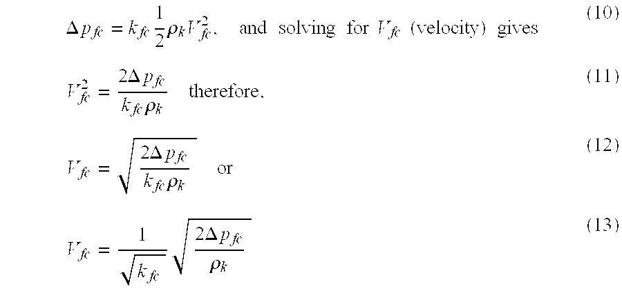
Per equation (9) defined above, volumetric flow rate (Qfc) equals the cross-sectional area of the pipe section (Ap) multiplied by the velocity- (Vfc) of the flow stream as follows: 
Therefore, utilizing a known or measured density (ρk) of the flow medium, the volumetric flow rate (Qfc) of the flow stream can be calculated by measuring the differential pressure (Δpfc) across the flow conditioner 12.
The calculated volumetric flow rate (Qfc) through the flow conditioner 12 provides additional data for the operator to verify the operation of the flowmeter 14. Namely, the processor 40 continuously compares the volumetric flowrate (Qvm) measured by the flowmeter 14 with the calculated volumetric flow rate (Qfc) through the flow conditioner 12 to identify actual flow rate changes versus problems with the measurement devices 12, 14. Although the flow rate values Qvm, Qfc will not be identical, the relationships between these values should remain constant over time. For example, the value of the measured Qvm may equal a certain percentage of the value of the calculated Qfc, and that percentage should remain constant over time. Therefore, in the configuration of FIG. 3, the flow conditioner 12 acts to condition the flow and also acts as a check meter for the primary flowmeter 14. This is especially advantageous because most existing metering systems, such as metering system 10, already include a flow conditioner 12 upstream of a flowmeter 14. Therefore, only a differential pressure transducer 16 is required for the flow conditioner 12 to perform the function of a check meter.
As understood by one of ordinary skill in the art, the density (ρ) of the flow stream may be calculated using standard compressibility data, e.g. AGA 8, based on the measured pressure and temperature in the pipeline and knowing the composition of the flow stream. The measured velocity (Vvm) from the flowmeter 14 and the measured differential pressure (Δpfc) across the flow conditioner 12 can also be used to calculate the density (ρc) of the flow medium. Starting with equation (10) defined above, and solving for density (ρc) yields: 
kfc is the loss-coefficient of the flow conditioner 12, which is a known value, experimentally determined for each flow conditioner 12. Therefore, using the flow velocity (Vvm) measured by the flowmeter 14, an approximation of the density (ρc) of the flow medium can be determined. Although the separately determined values of the flow stream density (ρc, ρk) will not be identical, the relationship between their values should remain constant over time.
As described above, the speed of sound (cus) in the flow stream 15 can be determined directly from the ultrasonic flowmeter 14 data. Because the preferred ultrasonic flowmeter 14 has two pairs of transducers (42, 44 and 46, 48), two separate measurements of the speed of sound (cus) may be calculated using the flowmeter 14 data. A separately calculated speed of sound (cc) can also be determined for a liquid flow stream 15 utilizing the liquid density. Namely, the speed of sound (cc) in a liquid of a known density (ρk) can be determined as follows: 
where Es is the bulk modulus of elasticity of the fluid, which is a constant.
Further, a separately calculated speed of sound (cc) can also be determined for a gaseous flow stream 15 as follows: 
cp is the specific heat of the gas at constant pressure, cv is the specific heat of the gas at constant volume, R is the gas constant, and T is the absolute temperature of the flow stream 15. Therefore, the speed of sound (cc) in the flow stream 15 can also be determined using independent methods and those results continuously monitored by the processor 40 and compared to the measured speed of sound (cus) for any divergence in the relationship between the measured and calculated values.
As described above, the preferred flowmeter 14 is an ultrasonic meter having two distinct measurement paths between two pairs of transducers 42, 44 and 46, 48. This configuration allows for two separate calculations of flow velocity (Vus) and speed of sound (cus) utilizing equations (7) and (8) above, thereby providing an internal check on the operation of the ultrasonic flowmeter 14. Additional diagnostic capabilities are provided by using the preferred ultrasonic flowmeter 14 in conjunction with the differential pressure transducer 16 adapted to measure across the flow conditioner 12. If the flow conditioner 12 is functioning properly, the two measurement paths of the ultrasonic meter 14 should measure approximately the same flow stream velocity (Vus). However, if debris collects in the flow conditioner 12, or other operational problems occur, the flow conditioner 12 will not properly condition the flow, so the velocity profile entering the ultrasonic flowmeter 14 will be disturbed. A disturbed velocity profile will likely cause the ultrasonic meter 14 to measure very different flow stream velocities (Vus) along the two measurement paths. Further, the differential pressure (Δpfc) across an obstructed flow conditioner 12 will also increase. Therefore, if a deviation between the two flow stream velocities (Vus) measured by the ultrasonic flowmeter 14 is accompanied by an increased differential pressure (Δpfc) across the flow conditioner 12, then the flow conditioner 12 is likely obstructed. If the deviating flow velocities (Vus) as measured along the two paths of the flowmeter 14 are not accompanied by an increased differential pressure, then there is likely an error in the velocity (Vus) measurements of the flowmeter 14. Therefore, the present invention provides additional diagnostic advantages not present in the prior art.
While, the above example is directed to the use of an ultrasonic flowmeter as the primary meter 14, many of the same concepts are applicable with other types of velocity meters, such as, for example, turbine, vortex, and electromagnetic meters. The present invention also finds useful application with an orifice meter as the primary meter 14. As expressed by equation (1) above, the volumetric flow rate (Q) through an orifice meter or any other differential pressure device, including the flow conditioner 12, is determined based on the measured differential pressure (Δp) and known or measured density (ρk) of the flow stream. Therefore, because the volumetric flow rate (QΔp) through an orifice meter, as expressed by equation (1), and the volumetric flow rate (Qfc) through the flow conditioner 12, as expressed by equation (14), each rely on the known density (ρk), the two volumetric flow rates can be expressed as a ratio to eliminate the density term, as follows: 
The variables on the right side of equation (19) are constants except for the measured differential pressures. Therefore: 
Thus, the ratio on the right side of equation (20), or alternatively, the ratio of the differential pressures, can be monitored since this ratio should remain constant over time absent operational problems with either the orifice meter or the flow conditioner 12.
While preferred embodiments of the present invention have been shown and described, those of ordinary skill in the art will understand that various modifications thereto can be made without departing from the scope of the present invention. For example, while an ultrasonic flowmeter is shown and described, the benefits of the present invention are equally applicable for other velocity meters. It is also understood that the present invention finds usefulness with orifice meters and other differential pressure measurement devices. Likewise, while various steps may be disclosed or claimed in a particular order herein, it is not intended that any particular order be required unless such order is inherent in the carrying-out of the claim or explicitly recited.
Claims (20)
1. A system for monitoring the conditions of a flow stream in a pipeline comprising:
a flow conditioner positioned in said pipeline upstream of a meter;
said meter;
means for measuring a differential pressure across said flow conditioner; and
a processor that collects data from said flow conditioner and said meter.
2. The system of claim 1 further comprising a temperature transducer and a pressure transducer.
3. The system of claim 1 wherein said meter is a velocity flowmeter.
4. The system of claim 3 wherein said meter is an ultrasonic flowmeter.
5. The system of claim 4 wherein said ultrasonic flowmeter comprises at least two pairs of transducers.
6. The system of claim 3 wherein said meter is a turbine flowmeter.
7. The system of claim 3 wherein said meter is an electromagnetic flowmeter.
8. The system of claim 3 wherein said meter is a vortex flowmeter.
9. The system of claim 1 wherein said meter is a differential pressure device.
10. The system of claim 9 wherein said meter is an orifice meter.
11. A method for monitoring the conditions of a flow stream in a pipeline comprising:
measuring a differential pressure across a flow conditioner positioned in the pipeline upstream of a flowmeter;
calculating a first volumetric flow rate through the pipeline using the measured differential pressure;
measuring a second volumetric flow rate using the flowmeter;
comparing the first volumetric flow rate to the second volumetric flow rate.
12. The method of claim 11 further comprising:
measuring a pressure and a temperature of the flow stream;
determining a velocity of the flow stream using the flowmeter;
calculating a first density of the flow stream using the measured pressure and temperature;
calculating a second density of the flow stream using the measured differential pressure and the measured velocity; and
comparing the first density to the second density.
13. The method of claim 12 further comprising:
determining a first speed of sound of the flow stream using the flowmeter;
calculating a second speed of sound in the flow stream; and
comparing the first speed of sound to the second speed of sound.
14. The method of claim 13 wherein the second speed of sound is calculated using the measured temperature and pressure of the flow stream.
15. The method of claim 13 wherein the second speed of sound is calculated using the second density and the measured pressure.
16. A method for monitoring the conditions of a flow stream in a pipeline comprising:
measuring a first differential pressure across a flow conditioner positioned in the pipeline upstream of a meter;
measuring a second differential pressure across a the meter; and
monitoring the ratio of the first differential pressure to the second differential pressure.
17. A method for monitoring the conditions of a flow stream in a pipeline comprising:
measuring a first differential pressure across a flow conditioner positioned in the pipeline upstream of a meter;
calculating a first volumetric flow rate from the first measured differential pressure;
measuring a second differential pressure across the meter;
calculating a second volumetric flow rate from the second measured differential pressure; and
comparing the first volumetric flow rate to the second volumetric flow rate.
18. A method for monitoring the performance of a flow conditioner in a pipeline comprising:
determining a first fluid velocity along a first measurement path of a flowmeter;
determining a second fluid velocity along a second measurement path of the flowmeter; and
comparing the first fluid velocity to the second fluid velocity;
wherein the flow conditioner is functioning properly when the first fluid velocity is substantially equal to the second fluid velocity.
19. The method of claim 18 wherein either the flow conditioner or the flowmeter is not functioning properly when the first fluid velocity is not substantially equal to the second fluid velocity.
20. The method of claim 18 further comprising measuring a differential pressure across the flow conditioner, wherein a differential pressure increase may indicate that the flow conditioner has debris trapped therein.
Priority Applications (1)
| Application Number | Priority Date | Filing Date | Title |
|---|---|---|---|
| US09/991,806 US6651514B2 (en) | 2001-11-16 | 2001-11-16 | Dual function flow conditioner and check meter |
Applications Claiming Priority (1)
| Application Number | Priority Date | Filing Date | Title |
|---|---|---|---|
| US09/991,806 US6651514B2 (en) | 2001-11-16 | 2001-11-16 | Dual function flow conditioner and check meter |
Publications (2)
| Publication Number | Publication Date |
|---|---|
| US20030094052A1 US20030094052A1 (en) | 2003-05-22 |
| US6651514B2 true US6651514B2 (en) | 2003-11-25 |
Family
ID=25537594
Family Applications (1)
| Application Number | Title | Priority Date | Filing Date |
|---|---|---|---|
| US09/991,806 Expired - Lifetime US6651514B2 (en) | 2001-11-16 | 2001-11-16 | Dual function flow conditioner and check meter |
Country Status (1)
| Country | Link |
|---|---|
| US (1) | US6651514B2 (en) |
Cited By (26)
| Publication number | Priority date | Publication date | Assignee | Title |
|---|---|---|---|---|
| US20030066359A1 (en) * | 2000-03-07 | 2003-04-10 | Weatherford/Lamb, Inc. | Distributed sound speed measurements for multiphase flow measurement |
| US20040139791A1 (en) * | 2003-01-21 | 2004-07-22 | Johansen Espen S. | Non-intrusive multiphase flow meter |
| US20060020685A1 (en) * | 2004-07-22 | 2006-01-26 | Guenter Spens | Quantity conversion interface for external program calls |
| US20060096641A1 (en) * | 2002-07-30 | 2006-05-11 | David Williams | Pipe coupling |
| US7234450B1 (en) * | 2005-04-05 | 2007-06-26 | Denso Corporation | Gas density ratio detector, gas concentration detector, and fuel vapor treatment apparatus |
| US20070209427A1 (en) * | 2006-03-07 | 2007-09-13 | General Electric Company | Metal particle sensor system |
| US20070277530A1 (en) * | 2006-05-31 | 2007-12-06 | Constantin Alexandru Dinu | Inlet flow conditioner for gas turbine engine fuel nozzle |
| US20090044636A1 (en) * | 2006-03-16 | 2009-02-19 | Sensorteknikk As | Method and device for recording characteristic state, amount and composition of a flowing medium |
| US20090266175A1 (en) * | 2008-04-25 | 2009-10-29 | Schlumberger Technology Corp. | Apparatus and method for characterizing two phase fluid flow |
| US7806145B1 (en) | 2009-10-23 | 2010-10-05 | Derold Gary Clark | Housing for a flow conditioner |
| US7992453B1 (en) | 2011-01-14 | 2011-08-09 | Cameron International Corporation | Erosion-resistant insert for flow measurement devices |
| US8387438B2 (en) | 2011-01-14 | 2013-03-05 | Cameron International Corporation | Flow measurement devices having constant relative geometries |
| WO2013052728A1 (en) * | 2011-10-05 | 2013-04-11 | Saudi Arabian Oil Company | Pulsating flow meter |
| CN103597325A (en) * | 2010-08-24 | 2014-02-19 | 因万西斯系统股份有限公司 | Multiphase metering |
| WO2014063004A1 (en) | 2012-10-19 | 2014-04-24 | Daniel Measurement And Control, Inc. | Ultrasonic flow metering system with an upstream pressure transducer |
| US20140238148A1 (en) * | 2013-02-27 | 2014-08-28 | Daniel Measurement And Control, Inc. | Ultrasonic flow metering with laminar to turbulent transition flow control |
| US8950188B2 (en) | 2011-09-09 | 2015-02-10 | General Electric Company | Turning guide for combustion fuel nozzle in gas turbine and method to turn fuel flow entering combustion chamber |
| CN105136381A (en) * | 2015-08-24 | 2015-12-09 | 洛阳三隆安装检修有限公司 | Reverse-blowing detection system |
| US9605695B2 (en) | 2013-05-21 | 2017-03-28 | Canada Pipeline Accessories, Co. Ltd. | Flow conditioner and method of designing same |
| US9625293B2 (en) | 2015-05-14 | 2017-04-18 | Daniel Sawchuk | Flow conditioner having integral pressure tap |
| US9752729B2 (en) | 2014-07-07 | 2017-09-05 | Canada Pipeline Accessories, Co. Ltd. | Systems and methods for generating swirl in pipelines |
| US20180066972A1 (en) * | 2016-09-08 | 2018-03-08 | Canada Pipeline Accessories, Co. Ltd. | Measurement Ring For Fluid Flow In A Pipeline |
| US10260537B2 (en) | 2014-03-20 | 2019-04-16 | Canada Pipeline Accessories, Co., Ltd. | Pipe assembly with stepped flow conditioners |
| US10274351B2 (en) | 2014-05-12 | 2019-04-30 | Schneider Electric Systems Usa, Inc. | Method of making a multivariable vortex flowmeter |
| CN110332963A (en) * | 2014-10-08 | 2019-10-15 | 迪特里奇标准公司 | Integrated hole board group part |
| US11085470B2 (en) | 2019-05-31 | 2021-08-10 | Kalsi Engineering, Inc. | Flow conditioning assembly |
Families Citing this family (11)
| Publication number | Priority date | Publication date | Assignee | Title |
|---|---|---|---|---|
| FR2860868B1 (en) * | 2003-10-13 | 2006-02-17 | Jean Michel Bargot | DEVICE FOR CONTROLLING THE DERIVATIVE OF AN ORGAN FOR MEASURING THE FLOW RATE AND / OR THE VOLUME OF A FLUID AND / OR CALIBRATING THE MEASURING MEMBER |
| CN101187660B (en) * | 2006-07-18 | 2012-01-11 | 中国石油天然气集团公司 | Double-slot type porous plate type mixed transportation metering device |
| NO326270B1 (en) | 2006-09-13 | 2008-10-27 | Fluenta As | Arrangement for painting fluid velocity |
| US20140060159A1 (en) * | 2012-08-31 | 2014-03-06 | Johnson & Johnson Consumer Companies, Inc. | Permeability flow cell and hydraulic conductance system |
| US9128020B2 (en) * | 2012-08-31 | 2015-09-08 | Johnson & Johnson Comsumer Inc. | Permeability flow cell and hydraulic conductance system |
| WO2015023435A1 (en) * | 2013-08-12 | 2015-02-19 | Applied Materials, Inc. | Recursive pumping for symmetrical gas exhaust to control critical dimension uniformity in plasma reactors |
| GB201700428D0 (en) * | 2017-01-10 | 2017-02-22 | Able Instr & Controls Ltd | Apparatus and method for flare flow measurement |
| US10823598B2 (en) * | 2017-03-23 | 2020-11-03 | Honeywell International Inc. | Apparatus and method for creating inferential process flow measurements using other process measurements |
| US11105664B2 (en) * | 2017-03-23 | 2021-08-31 | Honeywell International Inc. | Apparatus and method for creating inferential process flow measurements using flow restrictor and upstream and downstream pressure measurements |
| US20180306216A1 (en) * | 2017-04-24 | 2018-10-25 | Sensus Spectrum, Llc | Flow Conditioners for Use Normalizing Flow in Meters and Related Systems |
| CN112525307B (en) * | 2020-11-18 | 2023-07-18 | 苏州热工研究院有限公司 | Online monitoring device and method for performance of orifice valve |
Citations (14)
| Publication number | Priority date | Publication date | Assignee | Title |
|---|---|---|---|---|
| US2929248A (en) | 1957-11-13 | 1960-03-22 | Bailey Meter Co | Flow meter |
| US3840051A (en) | 1971-03-11 | 1974-10-08 | Mitsubishi Heavy Ind Ltd | Straightener |
| US4646575A (en) | 1983-05-11 | 1987-03-03 | British Gas Corporation | Ultrasonic flowmeter |
| US4875377A (en) * | 1986-03-27 | 1989-10-24 | Spirax Sarco Limited | Flowmeters |
| WO1991001452A1 (en) | 1989-07-20 | 1991-02-07 | Salford University Business Services Limited | Flow conditioner |
| US5138888A (en) * | 1990-09-24 | 1992-08-18 | Walmer Sr Warren L | Pivotable axis turbine flowmeter |
| EP0639776A1 (en) | 1993-08-17 | 1995-02-22 | Instromet Ultrasonics B.V. | Method and device for determining characteristics of the flow of a medium |
| US5495872A (en) | 1994-01-31 | 1996-03-05 | Integrity Measurement Partners | Flow conditioner for more accurate measurement of fluid flow |
| US5597961A (en) * | 1994-06-27 | 1997-01-28 | Texaco, Inc. | Two and three phase flow metering with a water cut monitor and an orifice plate |
| US5654551A (en) * | 1992-05-22 | 1997-08-05 | Commonwealth Scientific And Industrial Research Organisation | Method and apparatus for the measurement of the mass flow rates of fluid components in a multiphase slug flow |
| US5705753A (en) * | 1995-03-31 | 1998-01-06 | Caldon, Inc. | Apparatus for determining fluid flow |
| US5762107A (en) | 1993-09-14 | 1998-06-09 | Den Norske Stats Oljeselskap A.S. | Flow conditioner |
| US5773726A (en) * | 1996-06-04 | 1998-06-30 | Dieterich Technology Holding Corp. | Flow meter pitot tube with temperature sensor |
| US6298735B1 (en) * | 1999-04-23 | 2001-10-09 | Agilent Technologies, Inc. | Pneumotachometer having annular ring transducers |
-
2001
- 2001-11-16 US US09/991,806 patent/US6651514B2/en not_active Expired - Lifetime
Patent Citations (17)
| Publication number | Priority date | Publication date | Assignee | Title |
|---|---|---|---|---|
| US2929248A (en) | 1957-11-13 | 1960-03-22 | Bailey Meter Co | Flow meter |
| US3840051A (en) | 1971-03-11 | 1974-10-08 | Mitsubishi Heavy Ind Ltd | Straightener |
| US4646575A (en) | 1983-05-11 | 1987-03-03 | British Gas Corporation | Ultrasonic flowmeter |
| US4875377A (en) * | 1986-03-27 | 1989-10-24 | Spirax Sarco Limited | Flowmeters |
| WO1991001452A1 (en) | 1989-07-20 | 1991-02-07 | Salford University Business Services Limited | Flow conditioner |
| GB2235064A (en) | 1989-07-20 | 1991-02-20 | Univ Salford Business Services | A flow conditioner |
| US5138888A (en) * | 1990-09-24 | 1992-08-18 | Walmer Sr Warren L | Pivotable axis turbine flowmeter |
| US5654551A (en) * | 1992-05-22 | 1997-08-05 | Commonwealth Scientific And Industrial Research Organisation | Method and apparatus for the measurement of the mass flow rates of fluid components in a multiphase slug flow |
| US5546812A (en) | 1993-08-17 | 1996-08-20 | Servex B.V. | Method and device for determining characteristics of the flow of a medium |
| EP0639776A1 (en) | 1993-08-17 | 1995-02-22 | Instromet Ultrasonics B.V. | Method and device for determining characteristics of the flow of a medium |
| US5762107A (en) | 1993-09-14 | 1998-06-09 | Den Norske Stats Oljeselskap A.S. | Flow conditioner |
| US5495872A (en) | 1994-01-31 | 1996-03-05 | Integrity Measurement Partners | Flow conditioner for more accurate measurement of fluid flow |
| US5529093A (en) | 1994-01-31 | 1996-06-25 | Integrity Measurement Partners | Flow conditioner profile plate for more accurate measurement of fluid flow |
| US5597961A (en) * | 1994-06-27 | 1997-01-28 | Texaco, Inc. | Two and three phase flow metering with a water cut monitor and an orifice plate |
| US5705753A (en) * | 1995-03-31 | 1998-01-06 | Caldon, Inc. | Apparatus for determining fluid flow |
| US5773726A (en) * | 1996-06-04 | 1998-06-30 | Dieterich Technology Holding Corp. | Flow meter pitot tube with temperature sensor |
| US6298735B1 (en) * | 1999-04-23 | 2001-10-09 | Agilent Technologies, Inc. | Pneumotachometer having annular ring transducers |
Cited By (51)
| Publication number | Priority date | Publication date | Assignee | Title |
|---|---|---|---|---|
| US20030066359A1 (en) * | 2000-03-07 | 2003-04-10 | Weatherford/Lamb, Inc. | Distributed sound speed measurements for multiphase flow measurement |
| US6813962B2 (en) * | 2000-03-07 | 2004-11-09 | Weatherford/Lamb, Inc. | Distributed sound speed measurements for multiphase flow measurement |
| US20060096641A1 (en) * | 2002-07-30 | 2006-05-11 | David Williams | Pipe coupling |
| US7591192B2 (en) * | 2002-07-30 | 2009-09-22 | David Williams | Pipe coupling including an orifice plate and a rate of flow measuring device |
| US20040139791A1 (en) * | 2003-01-21 | 2004-07-22 | Johansen Espen S. | Non-intrusive multiphase flow meter |
| US6945095B2 (en) | 2003-01-21 | 2005-09-20 | Weatherford/Lamb, Inc. | Non-intrusive multiphase flow meter |
| US20060020685A1 (en) * | 2004-07-22 | 2006-01-26 | Guenter Spens | Quantity conversion interface for external program calls |
| US7962576B2 (en) * | 2004-07-22 | 2011-06-14 | Sap Ag | Quantity conversion interface for external program calls |
| US7234450B1 (en) * | 2005-04-05 | 2007-06-26 | Denso Corporation | Gas density ratio detector, gas concentration detector, and fuel vapor treatment apparatus |
| US20070157907A1 (en) * | 2005-04-05 | 2007-07-12 | Denso Corporation | Gas density ratio detector, gas concentration detector, and fuel vapor treatment apparatus |
| US7299683B2 (en) * | 2006-03-07 | 2007-11-27 | General Electric Company | Metal particle sensor system |
| US20070209427A1 (en) * | 2006-03-07 | 2007-09-13 | General Electric Company | Metal particle sensor system |
| US20090044636A1 (en) * | 2006-03-16 | 2009-02-19 | Sensorteknikk As | Method and device for recording characteristic state, amount and composition of a flowing medium |
| US7819022B2 (en) * | 2006-03-16 | 2010-10-26 | Sensorteknikk As | Method and device for recording characteristic state, amount and composition of a flowing medium |
| US20070277530A1 (en) * | 2006-05-31 | 2007-12-06 | Constantin Alexandru Dinu | Inlet flow conditioner for gas turbine engine fuel nozzle |
| US7637167B2 (en) | 2008-04-25 | 2009-12-29 | Schlumberger Technology Corporation | Apparatus and method for characterizing two phase fluid flow |
| WO2009130620A1 (en) | 2008-04-25 | 2009-10-29 | Schlumberger Canada Limited | Apparatus and method for characterizing two phase fluid flow |
| US20090266175A1 (en) * | 2008-04-25 | 2009-10-29 | Schlumberger Technology Corp. | Apparatus and method for characterizing two phase fluid flow |
| US7806145B1 (en) | 2009-10-23 | 2010-10-05 | Derold Gary Clark | Housing for a flow conditioner |
| CN103597325A (en) * | 2010-08-24 | 2014-02-19 | 因万西斯系统股份有限公司 | Multiphase metering |
| US8561480B2 (en) | 2011-01-14 | 2013-10-22 | Cameron International Corporation | Erosion-resistant insert for flow measurement devices |
| US8387438B2 (en) | 2011-01-14 | 2013-03-05 | Cameron International Corporation | Flow measurement devices having constant relative geometries |
| US7992453B1 (en) | 2011-01-14 | 2011-08-09 | Cameron International Corporation | Erosion-resistant insert for flow measurement devices |
| US9151658B2 (en) | 2011-01-14 | 2015-10-06 | Cameron International Corporation | Flow measurement devices having constant relative geometries |
| US8950188B2 (en) | 2011-09-09 | 2015-02-10 | General Electric Company | Turning guide for combustion fuel nozzle in gas turbine and method to turn fuel flow entering combustion chamber |
| US9032815B2 (en) * | 2011-10-05 | 2015-05-19 | Saudi Arabian Oil Company | Pulsating flow meter having a bluff body and an orifice plate to produce a pulsating flow |
| US20130086994A1 (en) * | 2011-10-05 | 2013-04-11 | Saudi Arabian Oil Company | Pulsating Flow Meter |
| EP3264050A1 (en) * | 2011-10-05 | 2018-01-03 | Saudi Arabian Oil Company | Pulsating flow meter |
| WO2013052728A1 (en) * | 2011-10-05 | 2013-04-11 | Saudi Arabian Oil Company | Pulsating flow meter |
| RU2601223C1 (en) * | 2012-10-19 | 2016-10-27 | ДЭНИЕЛ МЕЖЕМЕНТ энд КОНТРОЛ, ИНК. | Ultrasonic flow meter system with pressure transducer arranged upstream |
| WO2014063004A1 (en) | 2012-10-19 | 2014-04-24 | Daniel Measurement And Control, Inc. | Ultrasonic flow metering system with an upstream pressure transducer |
| US9151649B2 (en) | 2012-10-19 | 2015-10-06 | Daniel Measurement And Control, Inc. | Ultrasonic flow metering system with an upstream pressure transducer |
| CN103776516B (en) * | 2012-10-19 | 2017-05-17 | 丹尼尔测量和控制公司 | Ultrasonic flow metering system with upstream pressure transducer |
| CN103776516A (en) * | 2012-10-19 | 2014-05-07 | 丹尼尔测量和控制公司 | Ultrasonic flow metering system with upstream pressure transducer |
| EP2909587A4 (en) * | 2012-10-19 | 2016-08-17 | Daniel Measurement & Control | Ultrasonic flow metering system with an upstream pressure transducer |
| US10012521B2 (en) | 2013-02-27 | 2018-07-03 | Daniel Measurement And Control, Inc. | Ultrasonic flow metering with laminar to turbulent transition flow control |
| US20140238148A1 (en) * | 2013-02-27 | 2014-08-28 | Daniel Measurement And Control, Inc. | Ultrasonic flow metering with laminar to turbulent transition flow control |
| US9068870B2 (en) * | 2013-02-27 | 2015-06-30 | Daniel Measurement And Control, Inc. | Ultrasonic flow metering with laminar to turbulent transition flow control |
| US9605695B2 (en) | 2013-05-21 | 2017-03-28 | Canada Pipeline Accessories, Co. Ltd. | Flow conditioner and method of designing same |
| US10260537B2 (en) | 2014-03-20 | 2019-04-16 | Canada Pipeline Accessories, Co., Ltd. | Pipe assembly with stepped flow conditioners |
| US10274351B2 (en) | 2014-05-12 | 2019-04-30 | Schneider Electric Systems Usa, Inc. | Method of making a multivariable vortex flowmeter |
| US9752729B2 (en) | 2014-07-07 | 2017-09-05 | Canada Pipeline Accessories, Co. Ltd. | Systems and methods for generating swirl in pipelines |
| CN110332963A (en) * | 2014-10-08 | 2019-10-15 | 迪特里奇标准公司 | Integrated hole board group part |
| CN110332963B (en) * | 2014-10-08 | 2020-12-11 | 迪特里奇标准公司 | Integrated orifice plate assembly |
| US9625293B2 (en) | 2015-05-14 | 2017-04-18 | Daniel Sawchuk | Flow conditioner having integral pressure tap |
| CN105136381A (en) * | 2015-08-24 | 2015-12-09 | 洛阳三隆安装检修有限公司 | Reverse-blowing detection system |
| US20180066972A1 (en) * | 2016-09-08 | 2018-03-08 | Canada Pipeline Accessories, Co. Ltd. | Measurement Ring For Fluid Flow In A Pipeline |
| US10365143B2 (en) * | 2016-09-08 | 2019-07-30 | Canada Pipeline Accessories, Co., Ltd. | Measurement ring for fluid flow in a pipeline |
| US10677632B2 (en) | 2016-09-08 | 2020-06-09 | Canada Pipeline Accessories, Co., Ltd. | Measurement ring for fluid flow in a pipeline |
| US11085470B2 (en) | 2019-05-31 | 2021-08-10 | Kalsi Engineering, Inc. | Flow conditioning assembly |
| US11261891B2 (en) * | 2019-05-31 | 2022-03-01 | Kalsi Engineering, Inc. | Flow conditioning assembly |
Also Published As
| Publication number | Publication date |
|---|---|
| US20030094052A1 (en) | 2003-05-22 |
Similar Documents
| Publication | Publication Date | Title |
|---|---|---|
| US6651514B2 (en) | Dual function flow conditioner and check meter | |
| US11415447B2 (en) | Method for generating a diagnostic from a deviation of a flow meter parameter | |
| EP1886131B1 (en) | Method and ultrasonic meter system for determining pipe roughness | |
| US7770459B2 (en) | Differential pressure diagnostic for process fluid pulsations | |
| US9310237B2 (en) | Ultrasonic flow metering using compensated computed temperature | |
| RU2609436C1 (en) | Flow rate ultrasonic measurement using flow control at laminar flow transition to turbulent | |
| US8170812B2 (en) | Method and system for detecting deposit buildup within an ultrasonic flow meter | |
| US11255707B2 (en) | Hybrid flow meter with vortex sensor and differential pressure sensor arrangements with fluid flow meter diagnostics | |
| US9134155B2 (en) | Reynolds number based verification for ultrasonic flow metering systems | |
| RU2601223C1 (en) | Ultrasonic flow meter system with pressure transducer arranged upstream | |
| EP1825150A2 (en) | System and method for flow profile calibration correction for ultrasonic flowmeters | |
| Gajan et al. | The influence of pulsating flows on orifice plate flowmeters | |
| US9435681B2 (en) | Method for in-situ calibrating a differential pressure plus sonar flow meter system using dry gas conditions | |
| CN102207398A (en) | Ultrasonic flow measurement device and method for fuel terminal settlement | |
| US20030101804A1 (en) | Ultrasonic meter to detect pipeline corrosion and buildup | |
| US20160187172A1 (en) | Ultrasonic viscometer | |
| US20230119021A1 (en) | Energy Correlation Flow Meters | |
| Basics | EFFECTS AND CONTROL OF PULSATION IN GAS MEASUREMENT | |
| AU2011239252B2 (en) | Method for Generating a Diagnostic from a Deviation of a Flow Meter Parameter | |
| Hackett | Ultrasonic Meter Diagnostics-Basic | |
| Bowles Jr | EFFECTS AND CONTROL OF PULSATION IN GAS MEASUREMENT |
Legal Events
| Date | Code | Title | Description |
|---|---|---|---|
| AS | Assignment |
Owner name: DANIEL INDUSTRIES, INC., TEXAS Free format text: ASSIGNMENT OF ASSIGNORS INTEREST;ASSIGNOR:ZANKER, KLAUS JOACHIM;REEL/FRAME:012325/0660 Effective date: 20011115 |
|
| STCF | Information on status: patent grant |
Free format text: PATENTED CASE |
|
| FPAY | Fee payment |
Year of fee payment: 4 |
|
| FPAY | Fee payment |
Year of fee payment: 8 |
|
| FPAY | Fee payment |
Year of fee payment: 12 |