US6657153B2 - Electrode diffusion bonding - Google Patents
Electrode diffusion bonding Download PDFInfo
- Publication number
- US6657153B2 US6657153B2 US09/773,847 US77384701A US6657153B2 US 6657153 B2 US6657153 B2 US 6657153B2 US 77384701 A US77384701 A US 77384701A US 6657153 B2 US6657153 B2 US 6657153B2
- Authority
- US
- United States
- Prior art keywords
- separator
- emissive element
- electrode
- metallic holder
- emissive
- Prior art date
- Legal status (The legal status is an assumption and is not a legal conclusion. Google has not performed a legal analysis and makes no representation as to the accuracy of the status listed.)
- Expired - Lifetime, expires
Links
Images


Classifications
-
- B—PERFORMING OPERATIONS; TRANSPORTING
- B23—MACHINE TOOLS; METAL-WORKING NOT OTHERWISE PROVIDED FOR
- B23K—SOLDERING OR UNSOLDERING; WELDING; CLADDING OR PLATING BY SOLDERING OR WELDING; CUTTING BY APPLYING HEAT LOCALLY, e.g. FLAME CUTTING; WORKING BY LASER BEAM
- B23K20/00—Non-electric welding by applying impact or other pressure, with or without the application of heat, e.g. cladding or plating
- B23K20/02—Non-electric welding by applying impact or other pressure, with or without the application of heat, e.g. cladding or plating by means of a press ; Diffusion bonding
- B23K20/023—Thermo-compression bonding
-
- B—PERFORMING OPERATIONS; TRANSPORTING
- B23—MACHINE TOOLS; METAL-WORKING NOT OTHERWISE PROVIDED FOR
- B23K—SOLDERING OR UNSOLDERING; WELDING; CLADDING OR PLATING BY SOLDERING OR WELDING; CUTTING BY APPLYING HEAT LOCALLY, e.g. FLAME CUTTING; WORKING BY LASER BEAM
- B23K20/00—Non-electric welding by applying impact or other pressure, with or without the application of heat, e.g. cladding or plating
- B23K20/002—Non-electric welding by applying impact or other pressure, with or without the application of heat, e.g. cladding or plating specially adapted for particular articles or work
-
- H—ELECTRICITY
- H05—ELECTRIC TECHNIQUES NOT OTHERWISE PROVIDED FOR
- H05B—ELECTRIC HEATING; ELECTRIC LIGHT SOURCES NOT OTHERWISE PROVIDED FOR; CIRCUIT ARRANGEMENTS FOR ELECTRIC LIGHT SOURCES, IN GENERAL
- H05B7/00—Heating by electric discharge
-
- H—ELECTRICITY
- H05—ELECTRIC TECHNIQUES NOT OTHERWISE PROVIDED FOR
- H05H—PLASMA TECHNIQUE; PRODUCTION OF ACCELERATED ELECTRICALLY-CHARGED PARTICLES OR OF NEUTRONS; PRODUCTION OR ACCELERATION OF NEUTRAL MOLECULAR OR ATOMIC BEAMS
- H05H1/00—Generating plasma; Handling plasma
- H05H1/24—Generating plasma
- H05H1/26—Plasma torches
- H05H1/32—Plasma torches using an arc
- H05H1/34—Details, e.g. electrodes, nozzles
- H05H1/3442—Cathodes with inserted tip
-
- Y—GENERAL TAGGING OF NEW TECHNOLOGICAL DEVELOPMENTS; GENERAL TAGGING OF CROSS-SECTIONAL TECHNOLOGIES SPANNING OVER SEVERAL SECTIONS OF THE IPC; TECHNICAL SUBJECTS COVERED BY FORMER USPC CROSS-REFERENCE ART COLLECTIONS [XRACs] AND DIGESTS
- Y10—TECHNICAL SUBJECTS COVERED BY FORMER USPC
- Y10T—TECHNICAL SUBJECTS COVERED BY FORMER US CLASSIFICATION
- Y10T29/00—Metal working
- Y10T29/49—Method of mechanical manufacture
- Y10T29/49002—Electrical device making
- Y10T29/49082—Resistor making
- Y10T29/49083—Heater type
-
- Y—GENERAL TAGGING OF NEW TECHNOLOGICAL DEVELOPMENTS; GENERAL TAGGING OF CROSS-SECTIONAL TECHNOLOGIES SPANNING OVER SEVERAL SECTIONS OF THE IPC; TECHNICAL SUBJECTS COVERED BY FORMER USPC CROSS-REFERENCE ART COLLECTIONS [XRACs] AND DIGESTS
- Y10—TECHNICAL SUBJECTS COVERED BY FORMER USPC
- Y10T—TECHNICAL SUBJECTS COVERED BY FORMER US CLASSIFICATION
- Y10T29/00—Metal working
- Y10T29/49—Method of mechanical manufacture
- Y10T29/49002—Electrical device making
- Y10T29/49082—Resistor making
- Y10T29/49087—Resistor making with envelope or housing
-
- Y—GENERAL TAGGING OF NEW TECHNOLOGICAL DEVELOPMENTS; GENERAL TAGGING OF CROSS-SECTIONAL TECHNOLOGIES SPANNING OVER SEVERAL SECTIONS OF THE IPC; TECHNICAL SUBJECTS COVERED BY FORMER USPC CROSS-REFERENCE ART COLLECTIONS [XRACs] AND DIGESTS
- Y10—TECHNICAL SUBJECTS COVERED BY FORMER USPC
- Y10T—TECHNICAL SUBJECTS COVERED BY FORMER US CLASSIFICATION
- Y10T29/00—Metal working
- Y10T29/49—Method of mechanical manufacture
- Y10T29/49002—Electrical device making
- Y10T29/49117—Conductor or circuit manufacturing
- Y10T29/49124—On flat or curved insulated base, e.g., printed circuit, etc.
- Y10T29/49147—Assembling terminal to base
Definitions
- the present invention relates to plasma arc torches and, more particularly, to a method of forming an electrode for supporting an electric arc in a plasma arc torch.
- Plasma arc torches are commonly used for the working of metals, including cutting, welding, surface treatment, melting, and annealing. Such torches include an electrode which supports an arc which extends from the electrode to the workpiece in the transferred arc mode of operation. It is also conventional to surround the arc with a swirling vortex flow of gas, and in some torch designs it is conventional to also envelop the gas and arc with a swirling jet of water.
- the electrode used in conventional torches of the described type typically comprises an elongate tubular member composed of a material of high thermal conductivity, such as copper or a copper alloy.
- the forward or discharge end of the tubular electrode includes a bottom end wall having an emissive element embedded therein which supports the arc.
- the element is composed of a material which has a relatively low work function, which is defined in the art as the potential step, measured in electron volts (ev), which permits thermionic emission from the surface of a metal at a given temperature. In view of its low work function, the element is thus capable of readily emitting electrons when an electrical potential is applied thereto.
- Commonly used emissive materials include hafnium, zirconium, tungsten, and their alloys.
- Some electrodes include a relatively non-emissive separator, which is disposed about the emissive element and acts to prevent the arc from migrating from the emissive element to the copper holder.
- a problem associated with torches of the type described above is the short service life of the electrode, particularly when the torch is used with an oxidizing gas, such as oxygen or air. More particularly, the gas tends to rapidly oxidize the copper of the electrode that surrounds the emissive element, and as the copper oxidizes, its work function decreases. As a result, a point is reached at which the oxidized copper surrounding the emissive element begins to support the arc, rather than the element. When this happens, the copper oxide and the supporting copper melt, resulting in early destruction and failure of the electrode.
- an oxidizing gas such as oxygen or air. More particularly, the gas tends to rapidly oxidize the copper of the electrode that surrounds the emissive element, and as the copper oxidizes, its work function decreases. As a result, a point is reached at which the oxidized copper surrounding the emissive element begins to support the arc, rather than the element. When this happens, the copper oxide and the supporting copper melt, resulting in early destruction and failure of
- the assignee of the present application has previously developed an electrode with significantly improved service life, as described in U.S. Pat. No. 5,023,425, the entire disclosure of which is hereby incorporated by reference.
- the '425 patent discloses an electrode comprising a metallic tubular holder supporting an emissive element at a front end thereof, and having a relatively non-emissive separator or sleeve surrounding the emissive element and interposed between the emissive element and the metallic holder.
- the '425 patent describes the fabrication of the metallic holder by axially drilling the separator and force fitting the emissive element therein. The resulting interference or frictional fit holds the emissive element in the separator, and the front face of the assembly is then finished to form a common front planar surface.
- U.S. Pat. No. 5,200,594 describes a pressing process wherein the emissive element is coated with nickel and silver films, and then inserted into a metallic holder. The base of the electrode having the emissive element inserted therein is pressed from the periphery to the center by using pressing tools. The pressing process increases the bond between the films coating the emissive element and the metallic holder, which therefore improves the life span of the electrode.
- the electrode and process of forming an electrode as described by the '594 patent increases the fabrication cost of the electrode due to the multiple film layers that must be applied in order to form a strong bond with the metallic holder.
- electrodes according to the '425 patent although a great advance over prior electrodes, still have a life span that electrode manufacturers and users would like to see extended. Thus, there is a need to increase the life span and performance of an electrode without requiring extra or special coatings, films, or brazing materials to be applied between the emissive element, separator, and/or metallic holder.
- the present invention was developed to improve upon conventional methods of making electrodes, and more particularly methods of making electrodes disclosed in the above-referenced '594 patent. It has been discovered that the difficulties of the electrodes described above, namely increasing the life and performance of electrodes for plasma torches, can be overcome by providing an electrode by heating the electrode near the end of the manufacturing process to accelerate diffusion bonding between elements of the electrode.
- the “post-assembly” heating process forms stronger bonds between components of the electrode, which results in longer time and better performance of the electrode.
- a method of fabricating an electrode according to the present invention includes forming an assembly by inserting an emissive element having a relatively low work function in a relatively non-emissive separator.
- the separator which is formed of a metallic material having a work function greater than that of the emissive element, has inner and outer surfaces wherein the inner surface of the separator is in face-to-face contact with the emissive element.
- the assembly is positioned in a cavity defined by a metallic holder, the cavity being in surface-to-surface contact with the outer surface of the separator. After the assembly is in place, the metallic holder and assembly are heated to accelerate diffusion bonding between the emissive element and separator, and between the separator and the metallic holder.
- the heating step comprises heating the metallic holder and the assembly to between about 1400°-1420° F. for at least 5 hours and, more preferably, to about 1410° F. for about 6.5 hours.
- diffusion bonding which also takes place at room or ambient temperatures but orders of magnitude slower, occurs relatively rapidly to increase the bonds between the emissive element and separator, and between the separator and the metallic holder. Because these elements are more secure, the Inventors have discovered that the life span of the electrode is greatly improved over conventional electrodes. In addition, brazing materials or coatings are not used according to the methods of the present invention, which thereby decreases the costs of manufacturing the electrode.
- the heating process is followed by a crimping process, preferably after allowing the electrode to cool to ambient or room temperature.
- the crimping process includes using pressing tools to press the outer surface of the metallic holder radially inwardly towards the cavity defined therein in order to reduce the overall outer shape of the metallic holder.
- the crimping process reduces the outer diameter or shape of the metallic holder by between about 0.050-0.100 inches, which is sufficient to add further strength and hardness to the electrode.
- the crimping process also substantially eliminates any voids present between the emissive element and the separator, and between the separator and the metallic holder that can lead to early failure of the electrode.
- the present invention provides methods of making an electrode having stronger bonds between elements of the electrode, which improves the strength and operational life span of the electrode. Furthermore, the methods of making an electrode according to the present invention are directed to electrodes having no brazing materials, coatings, or other layers present between the emissive element, separator, or metallic holder. In this regard, the cost and complexity of fabricating the electrode is reduced.
- FIG. 1 is a sectioned side elevational view of a plasma arc torch which embodies the features of the present invention
- FIG. 2 is an enlarged perspective view of an electrode in accordance with the present invention.
- FIG. 3 is an enlarged sectional side view of an electrode in accordance with the present invention.
- FIGS. 4-7 are schematic views illustrating the steps of a preferred method of fabricating the electrode in accordance with the invention.
- FIG. 8 is a greatly enlarged sectional view of the electrode of the present invention as seen along lines 8 — 8 of FIG. 7 shortly after a heating operation;
- FIG. 9 is an enlarged sectional side view illustrating the steps of a preferred method of fabricating the electrode in accordance with the invention.
- FIG. 10 is an end elevational view of the finished electrode in accordance with the present invention.
- the torch 10 includes a nozzle assembly 12 and a tubular electrode 14 .
- the electrode 14 preferably is made of copper or a copper alloy, and is composed of an upper tubular member 15 and a lower cup-shaped member or holder 16 .
- the upper tubular member 15 is of elongate open tubular construction and defines the longitudinal axis of the torch 10 .
- the upper tubular member 15 includes an internally threaded lower end portion 17 .
- the holder 16 is also of tubular construction, and includes a lower front end and an upper rear end.
- a transverse end wall 18 closes the front end of the holder 16 , and the transverse end wall 18 defines an outer front face 20 .
- the rear end of the holder 16 is externally threaded and is threadedly joined to the lower end portion 17 of the upper tubular member 15 .
- the holder 16 is open at the rear end 19 thereof such that the holder is of cup-shaped configuration and defines an internal cavity 22 .
- the internal cavity 22 has a surface 31 that includes a cylindrical post 23 extending into the internal cavity along the longitudinal axis.
- a generally cylindrical cavity 24 is formed in the front face 20 of the end wall 18 and extends rearwardly along the longitudinal axis and into a portion of the holder 16 .
- the cavity 24 includes inner side surface 27 .
- a relatively non-emissive separator 32 is positioned in the cavity 24 and is disposed coaxially along the longitudinal axis.
- the separator 32 has an outer peripheral wall 33 extending substantially the length of the cavity 24 .
- the peripheral wall 33 is illustrated as having a substantially constant outer diameter over the length of the separator, although it will be appreciated that other geometric configurations would be consistent with the scope of the invention, such as frustoconical.
- the separator 32 also defines an internal cavity 35 having a surface 37 .
- the separator 32 also includes an outer end face 36 which is generally flush with the front face 20 of the holder 16 .
- An emissive element or insert 28 is positioned in the separator 32 and is disposed coaxially along the longitudinal axis. More specifically, the emissive element 28 and the separator 32 form an assembly wherein the emissive element is secured to the separator by an interference or press fit coupled with an advantageous form of diffusion bonding, which is effected by heating the emissive element and separator, as discussed more fully below.
- the emissive element 28 has a circular outer end face 29 lying in the plane of the front face 20 of the holder 16 and the outer end face 36 of the separator 32 .
- the emissive element 28 also includes a generally circular inner end face 30 which is disposed in the cavity 35 defined by the separator 32 and is opposite the outer end face 29 .
- the inner end face 30 can have other shapes, such as pointed, polygonal, or spherical, in order to assist in securing the emissive element to the separator 32 .
- the diameter of the emissive element 28 is about 30-80 percent of the outer diameter of the end face 36 of the separator 32 , which has a radial thickness of at least about 0.25 mm (0.01 inch) at the outer end face 36 and along its entire length.
- the emissive element 28 typically has a diameter of about 0.08 inch and a length of about 0.25 inch, and the outer diameter of the separator 32 is about 0.25 inch.
- the emissive element 28 is composed of a metallic material having a relatively low work function, such as in a range of about 2.7 to 4.2 ev, so as to be capable of readily emitting electrons upon an electrical potential being applied thereto.
- a metallic material having a relatively low work function such as in a range of about 2.7 to 4.2 ev, so as to be capable of readily emitting electrons upon an electrical potential being applied thereto.
- Suitable examples of such materials are hafnium, zirconium, tungsten, and mixtures thereof.
- the separator 32 is composed of a metallic material having a work function that is greater than that of the material of the holder 16 , according to values presented in Smithells Metal Reference Book, 6th Ed. More specifically, it is preferred that the separator 32 be composed of a metallic material having a work function of at least about 4.3 ev.
- the separator 32 comprises silver, although other metallic materials, such as gold, platinum, rhodium, iridium, palladium, nickel, and alloys thereof, may also be used.
- the selected material for the separator 32 should have high thermal conductivity, high resistance to oxidation, high melting point, high work function, and low cost. Although it is difficult to maximize all of these properties in one material, silver is preferred due to its high thermal conductivity.
- the separator 32 is composed of a silver alloy material comprising silver alloyed with about 0.25 to 10 percent of an additional material selected from the group consisting of copper, aluminum, iron, lead, zinc, and alloys thereof, such as, for example, sterling silver.
- the additional material may be in elemental or oxide form, and thus the term “copper” as used herein is intended to refer to both the elemental form as well as the oxide form, and similarly for the terms “aluminum” and the like.
- the electrode 14 is mounted in a plasma torch body 38 , which includes gas and liquid passageways 40 and 42 , respectively.
- the torch body 38 is surrounded by an outer insulated housing member 44 .
- a tube 46 is suspended within the central bore 48 of the electrode 14 for circulating a liquid cooling medium, such as water, through the electrode 14 .
- the tube 46 has an outer diameter smaller than the diameter of the bore 48 such that a space 49 exists between the tube 46 and the bore 48 to allow water to flow therein upon being discharged from the open lower end of the tube 46 .
- the water flows from a source (not shown) through the tube 46 , inside the internal cavity 22 and the holder 16 , and back through the space 49 to an opening 52 in the torch body 38 and to a drain hose (not shown).
- the passageway 42 directs injection water into the nozzle assembly 12 where it is converted into a swirling vortex for surrounding the plasma arc, as further explained below.
- the gas passageway 40 directs gas from a suitable source (not shown), through a gas baffle 54 of suitable high temperature material into a gas plenum chamber 56 via inlet holes 58 .
- the inlet holes 58 are arranged so as to cause the gas to enter in the plenum chamber 56 in a swirling fashion.
- the gas flows out of the plenum chamber 56 through coaxial bores 60 and 62 of the nozzle assembly 12 .
- the electrode 14 retains the gas baffle 54 .
- a high-temperature plastic insulator body 55 electrically insulates the nozzle assembly 12 from the electrode 14 .
- the nozzle assembly 12 comprises an upper nozzle member 63 which defines the first bore 60 , and a lower nozzle member 64 which defines the second bore 62 .
- the upper nozzle member 63 is preferably a metallic material
- the lower nozzle member 64 is preferably a metallic or ceramic material.
- the bore 60 of the upper nozzle member 63 is in axial alignment with the longitudinal axis of the torch electrode 14 .
- the lower nozzle member 64 is separated from the upper nozzle member 63 by a plastic spacer element 65 and a water swirl ring 66 .
- the space provided between the upper nozzle member 63 and the lower nozzle member 64 forms a water chamber 67 .
- the lower nozzle member 64 comprises a cylindrical body portion 70 that defines a forward or lower end portion and a rearward or upper end portion, with the bore 62 extending coaxially through the body portion 70 .
- An annular mounting flange 71 is positioned on the rearward end portion, and a frustoconical surface 72 is formed on the exterior of the forward end portion coaxial with the second bore 62 .
- the annular flange 71 is supported from below by an inwardly directed flange 73 at the lower end of the cup 74 , with the cup 74 being detachably mounted by interconnecting threads to the outer housing member 44 .
- a gasket 75 is disposed between the two flanges 71 and 73 .
- the bore 62 in the lower nozzle member 64 is cylindrical, and is maintained in axial alignment with the bore 60 in the upper nozzle member 63 by a centering sleeve 78 of any suitable plastic material.
- the injection ports 87 are tangentially disposed around the swirl ring 66 , to impart a swirl component of velocity to the water flow in the water chamber 67 .
- a power supply (not shown) is connected to the torch electrode 14 in a series circuit relationship with a metal workpiece, which is usually grounded.
- a plasma arc is established between the emissive element 28 of the electrode, which acts as the cathode terminal for the arc, and the workpiece, which is connected to the anode of the power supply and is positioned below the lower nozzle member 64 .
- the plasma arc is started in a conventional manner by momentarily establishing a pilot arc between the electrode 14 and the nozzle assembly 12 , and the arc is then transferred to the workpiece through the bores 60 and 62 .
- FIGS. 4-7 illustrate a preferred method of fabricating the electrode in accordance with the present invention.
- the emissive insert 28 is disposed in the cavity 35 defined by the separator 32 .
- the emissive element 28 is disposed in the cavity 35 of the separator 32 by using a tool 80 having a generally planar circular working surface 81 .
- the tool 80 is placed with the working surface 81 in contact with the emissive element 28 in the cavity 35 .
- the outer diameter of the working surface 81 is slightly smaller than the diameter of the cavity 35 defined by the separator 32 .
- the tool 80 is held with the working surface 81 generally coaxial with the longitudinal axis of the torch 10 , and force is applied to the tool so as to impart axial compressive forces to the emissive element 28 and the separator 32 along the longitudinal axis.
- the tool 80 may be positioned in contact with the emissive element 28 and separator 32 and then struck by a suitable device, such as the ram of a machine. Regardless of the specific technique used, sufficient force should be imparted so as to position the emissive element 28 in the cavity 35 of the separator 32 such that the inner end face 30 of the emissive element is in surface-to-surface contact with the separator.
- the compressing action of the emissive element 28 also results in the emissive element and the separator 32 being slightly deformed radially outwardly such that the emissive element 28 is tightly gripped and retained by the separator in a surface-to-surface relationship.
- a cylindrical blank 94 of copper or copper alloy having a front face 95 and an opposite rear face 96 .
- a generally cylindrical bore is then formed, such as by drilling, in the front face 95 along the longitudinal axis so as to form the cavity 24 as described above.
- the emissive element 28 and separator 32 assembly is then inserted into the cavity 24 , such as by press-fitting, such that the peripheral wall 33 of the separator slidably engages the inner wall 27 of the cavity and is secured thereto in a surface-to-surface, frictional relationship.
- a tool 98 having a generally planar circular working surface 100 is placed with the working surface in contact with the end faces 29 and 36 of the emissive element 28 and separator 32 , respectively.
- the outer diameter of the working surface 100 is slightly smaller than the diameter of the cavity 24 in the cylindrical blank 94 .
- the tool 98 is held with the working surface 100 generally coaxial with the longitudinal axis of the torch 10 , and force is applied to the tool so as to impart axial compressive forces to the emissive element 28 and the separator 32 along the longitudinal axis.
- the tool 98 may be positioned in contact with the emissive element 28 and separator 32 and then struck by a suitable device, such as the ram of a machine.
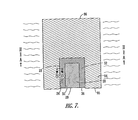
- sufficient force is imparted so as to cause the emissive element 28 and the separator 32 to be deformed radially outwardly such that the emissive element is tightly gripped and retained by the separator, and the separator is tightly gripped and retained by the cavity 24 , as shown in FIG. 7 .
- FIG. 7 also shows the addition of heat to the cylindrical blank 94 , which results in improved properties and life span of the electrode.
- the heating process can occur after the emissive element 28 and separator 32 assembly has been positioned in the metallic holder or blank. The heating process could also be performed after further machining steps are performed on the cylindrical blank, as described below. The exact heating process is dependent on the materials used in the emissive element 28 and the material used in the separator 32 . In particular, the heating process is determined by the melting temperature of the materials, and is performed to accelerate diffusion bonding between the emissive element 28 and the separator 32 , and the separator and the metallic holder or blank.
- Diffusion bonding occurs when two pieces of metal are pressed and held together. Atoms of one metal will migrate to the other metal and vice-versa. At room temperature, significant diffusion bonding may take several years to develop, but it will occur. However, the Inventors have discovered that by heating the electrode after the assembly has been inserted in the metallic holder or blank, the rate of diffusion bonding increases. Specifically, the Inventors have discovered that the amount of diffusion bonding between the emissive element 28 and the separator 32 is proportional to the temperature and the square root of heating time. The same is generally true for the separator 32 and the metallic blank 94 .
- the electrode should be heated to a point where the diffusion bonding process is accelerated, but not to a point where the materials forming the emissive element 28 , separator 32 , or metallic blank 94 begin to melt, as this can destroy the diffusion bond between the metallic blank and the separator, and can result in adverse alloying of the separator material.
- the emissive element 28 is formed of hafnium, and the separator 32 is formed primarily of silver, such as sterling silver.
- the metallic blank 94 is formed of copper. After the emissive element 28 and separator 32 assembly is positioned in the blank, which according to one embodiment includes plastically deforming the separator 32 between the emissive element and metallic blank 94 , the assembly is heated to a temperature below the melting points of the emissive element, separator, and metallic blank.
- the electrode is heated to a temperature below 1432° F., which is the melting temperature of copper-silver eutectic alloy, such as heating the electrode to between about 1400°-1420° F., and more particularly to about 1410° F., for at least 5 hours. In this example, the electrode is heated for about 6.5 hours.
- the resulting diffusion bonds that occur between the emissive element 28 , separator 32 , and between the separator and the metallic blank 94 have thicknesses of about 0.0004′′ and 0.005′′, respectively. At these thicknesses, the emissive element 28 , separator 32 , and metallic blank 94 are strongly bonded together, which allows the torch to operate longer before the electrode fails.
- the intra-metallic bonds i.e., the bonds between the individual molecules of the material
- the intra-metallic bonds of each of these components has an initial stress level or stressed state, which results from stressing the intra-metallic bonds during formation of the individual component.
- the intra-metallic bonds of each component are resistant to forming diffusion bonds with adjacent materials.
- the heating step allows the intra-metallic bonds to re-align and fall into a lower energy state.
- the intra-metallic bonds are less resistant to forming diffusion bonds with adjacent materials, which thereby permits the more rapid formation of the diffusion bonds discussed above.
- FIG. 8 shows a detailed cross-sectional view of the separator 32 and the metallic holder 16 after the heating process shown in FIG. 7 .
- FIG. 8 shows a greatly enlarged view of the interface between the separator 32 and the metallic holder 16 along lines 8 — 8 in FIG. 7 .
- the separator 32 is formed primarily of silver
- the metallic holder 16 is formed primarily of copper.
- the heating process causes diffusion bonding to occur between the separator 32 and the metallic holder 16 , which results in small portions or formations 88 of the metallic holder 16 to migrate beyond the interface and into the separator 32 .
- FIG. 9 shows another process that also enhances the strength of the electrode and thus the operational life span of the electrode.
- FIG. 8 illustrates a crimping process at the front end of the electrode using pressing tools 97 .
- the pressing tools 97 act radially inwardly against the outer surface of the metallic blank 94 to press the blank, separator 32 , and emissive element 28 together, which further bonds the materials together.
- the diameter of the metallic blank 94 is reduced an amount d, which in one embodiment is between about 0.050-0.100 inches.
- the outer shape can also be changed during crimping, such as from a cylindrical blank to a hexagonal shape as illustrated.
- the crimping process could also be performed after the blank 94 has been machined into a near-final form.
- the crimping process provides at least two benefits.
- One benefit is that the pressing action causes any voids present between the emissive element 28 , separator 32 , and metallic blank 94 to be substantially eliminated. This is important because voids act as stress concentrators, which may lead to early failure of the electrode.
- Another benefit is that the pressing action restores the yield strength and hardness of the emissive element 28 , separator 32 , and metallic blank 94 that were lost during the heating process discussed above. More specifically, the crimping process acts to increase the stress level of the intra-metallic bonds of these components back to near the initial stress level.
- the diffusion bonds discussed above have been formed and stabilized by heating the components and letting the electrode come back down to ambient or room temperature, respectively.
- the crimping process acts to secure or “lock in” the diffusion bonds formed between the emissive element 28 , separator 32 , and metallic blank 94 .
- the crimping process includes reducing the electrode from a cylindrical shape having a diameter of about 0.625′′ to a hexagonal shape having an outer diameter of about 0.497′′.
- Table I shows electrode operational life span at 260 Amps.
- the average experimental electrodes in Table I had a life span of approximately 664 minutes, with a standard deviation of 47 minutes, whereas conventional electrodes not receiving the post-assembly heating and crimping processes according to the present invention have an average life span of 475 minutes.
- Table II shows electrode operational life span at 300 Amps.
- the average experimental electrodes in Table II had a life span of approximately 300 minutes, with a standard deviation of 50 minutes, whereas conventional electrodes not receiving the post-assembly heating and crimping processes according to the present invention have an average life span of 195 minutes.
- the plasma arc torch used for obtaining the test results shown in Tables I and II was ESAB Torch PT-15XL using oxygen as the plasma gas.
- the rear face 96 of the cylindrical blank 94 is machined to form an open cup-shaped configuration defining the cavity 22 therein.
- the cavity 22 includes an internal annular recess 82 which defines the cylindrical post 23 and coaxially surrounds portions of the separator 32 and emissive element 28 .
- the internal annular recess 82 includes an internal surface 83 .
- the internal annular recess 82 is formed, such as by trepanning or other machining operation, to define the cylindrical post 23 .
- the external periphery of the cylindrical blank 94 is also shaped as desired, including formation of external threads 102 at the rear end 19 of the holder 16 .
- the front face 95 of the blank 94 and the end faces 29 and 36 of the emissive element 28 and separator 32 , respectively, are machined so that they are substantially flat and flush with one another.
- FIG. 10 depicts an end elevational view of the holder 16 . It can be seen that the end face 36 of the separator 32 separates the end face 29 of the emissive element 28 from the front face 20 of the holder 16 .
- the end face 36 is annular having an inner perimeter 104 and an outer perimeter 106 .
- the separator 32 serves to discourage the arc from detaching from the emissive element and becoming attached to the holder 16 .
- the present invention provides an electrode 14 for use in a plasma arc torch and a method of making an electrode wherein a post-assembly heating process is applied to the electrode to accelerate diffusion bonding between the emissive element 28 , separator 32 , and metallic holder 16 .
- a crimping process can also be applied to further strengthen and bond these components of the electrode 14 .
- no brazing layers, coatings, or other materials are used between the emissive element 28 , separator 32 , and metallic holder or blank.
- the emissive element and separator, and the separator and metallic holder have surface-to-surface relationships, respectively.
- the cost of fabricating an electrode according to the present invention is reduced, while still providing a strong and long-lasting electrode.
Abstract
Description
| TABLE I | |||
| ELECTRODE | LIFE SPAN @ 260 AMPS | ||
| CONVENTIONAL | 475 | ||
| EXPERIMENTAL | 675 | ||
| EXPERIMENTAL | 677 | ||
| EXPERIMENTAL | 733 | ||
| EXPERIMENTAL | 638 | ||
| EXPERIMENTAL | 663 | ||
| EXPERIMENTAL | 607 | ||
| TABLE II | |||
| ELECTRODE | LIFE SPAN @ 300 AMPS | ||
| CONVENTIONAL | 195 | ||
| EXPERIMENTAL | 248 | ||
| EXPERIMENTAL | 264 | ||
| EXPERIMENTAL | 330 | ||
| EXPERIMENTAL | 361 | ||
| EXPERIMENTAL | 210 | ||
| EXPERIMENTAL | 272 | ||
| EXPERIMENTAL | 272 | ||
| EXPERIMENTAL | 330 | ||
| EXPERIMENTAL | 379 | ||
| EXPERIMENTAL | 306 | ||
| EXPERIMENTAL | 340 | ||
| EXPERIMENTAL | 276 | ||
Claims (20)
Priority Applications (2)
| Application Number | Priority Date | Filing Date | Title |
|---|---|---|---|
| US09/773,847 US6657153B2 (en) | 2001-01-31 | 2001-01-31 | Electrode diffusion bonding |
| CA002357808A CA2357808C (en) | 2001-01-31 | 2001-09-26 | Electrode diffusion bonding |
Applications Claiming Priority (1)
| Application Number | Priority Date | Filing Date | Title |
|---|---|---|---|
| US09/773,847 US6657153B2 (en) | 2001-01-31 | 2001-01-31 | Electrode diffusion bonding |
Publications (2)
| Publication Number | Publication Date |
|---|---|
| US20020139788A1 US20020139788A1 (en) | 2002-10-03 |
| US6657153B2 true US6657153B2 (en) | 2003-12-02 |
Family
ID=25099499
Family Applications (1)
| Application Number | Title | Priority Date | Filing Date |
|---|---|---|---|
| US09/773,847 Expired - Lifetime US6657153B2 (en) | 2001-01-31 | 2001-01-31 | Electrode diffusion bonding |
Country Status (2)
| Country | Link |
|---|---|
| US (1) | US6657153B2 (en) |
| CA (1) | CA2357808C (en) |
Cited By (7)
| Publication number | Priority date | Publication date | Assignee | Title |
|---|---|---|---|---|
| US20020125224A1 (en) * | 2001-03-09 | 2002-09-12 | Cook David J. | Composite electrode for a plasma arc torch |
| US20040200810A1 (en) * | 2003-04-11 | 2004-10-14 | Hypertherm, Inc. | Method and apparatus for alignment of components of a plasma arc torch |
| US20060102598A1 (en) * | 2004-11-16 | 2006-05-18 | Hypertherm, Inc. | Plasma arc torch having an electrode with internal passages |
| US20070173907A1 (en) * | 2006-01-26 | 2007-07-26 | Thermal Dynamics Corporation | Hybrid electrode for a plasma arc torch and methods of manufacture thereof |
| US20080116179A1 (en) * | 2003-04-11 | 2008-05-22 | Hypertherm, Inc. | Method and apparatus for alignment of components of a plasma arc torch |
| US20080237202A1 (en) * | 2004-11-16 | 2008-10-02 | Hypertherm, Inc. | Plasma Arc Torch Having an Electrode With Internal Passages |
| US11678428B2 (en) | 2019-08-02 | 2023-06-13 | The Esab Group, Inc. | Method of assembling an electrode |
Families Citing this family (4)
| Publication number | Priority date | Publication date | Assignee | Title |
|---|---|---|---|---|
| CN102430827B (en) * | 2011-10-09 | 2013-08-07 | 上海工程技术大学 | Vacuum brazing method of plasma cutting electrode |
| US8525069B1 (en) * | 2012-05-18 | 2013-09-03 | Hypertherm, Inc. | Method and apparatus for improved cutting life of a plasma arc torch |
| CN111360489B (en) * | 2020-03-24 | 2021-11-02 | 西安天力金属复合材料股份有限公司 | Preparation method of silver-copper composite electrode |
| WO2024068182A1 (en) * | 2022-09-26 | 2024-04-04 | Kjellberg-Stiftung | Component such as a wearing part for an arc torch, in particular a plasma burner or plasma cutting torch, arc torch comprising same, and method of plasma cutting |
Citations (16)
| Publication number | Priority date | Publication date | Assignee | Title |
|---|---|---|---|---|
| US3198932A (en) | 1962-03-30 | 1965-08-03 | Union Carbide Corp | Arc electrode |
| US3930139A (en) | 1974-05-28 | 1975-12-30 | David Grigorievich Bykhovsky | Nonconsumable electrode for oxygen arc working |
| US4304984A (en) | 1978-05-11 | 1981-12-08 | Bolotnikov Arkady L | Non-consumable electrode for plasma-arc welding |
| US4766349A (en) | 1985-06-05 | 1988-08-23 | Aga Aktiebolag | Arc electrode |
| US5021627A (en) | 1989-02-13 | 1991-06-04 | Hoesch Stahl Ag | Electrode for resistance welding surface-treated sheets of steel and method of manufacturing such electrodes |
| US5023425A (en) | 1990-01-17 | 1991-06-11 | Esab Welding Products, Inc. | Electrode for plasma arc torch and method of fabricating same |
| US5097111A (en) | 1990-01-17 | 1992-03-17 | Esab Welding Products, Inc. | Electrode for plasma arc torch and method of fabricating same |
| JPH04147772A (en) | 1990-10-08 | 1992-05-21 | Koike Sanso Kogyo Co Ltd | Nonconsumable electrode for arc working |
| US5200594A (en) | 1990-06-26 | 1993-04-06 | Daihen Corporation | Electrode for use in plasma arc working torch |
| US5628924A (en) | 1993-02-24 | 1997-05-13 | Komatsu, Ltd. | Plasma arc torch |
| US5676864A (en) | 1997-01-02 | 1997-10-14 | American Torch Tip Company | Electrode for plasma arc torch |
| US5767478A (en) | 1997-01-02 | 1998-06-16 | American Torch Tip Company | Electrode for plasma arc torch |
| US5908567A (en) | 1995-04-19 | 1999-06-01 | Komatsu Ltd. | Electrode for plasma arc torch |
| US6020572A (en) | 1998-08-12 | 2000-02-01 | The Esab Group, Inc. | Electrode for plasma arc torch and method of making same |
| US6452130B1 (en) * | 2000-10-24 | 2002-09-17 | The Esab Group, Inc. | Electrode with brazed separator and method of making same |
| US6483070B1 (en) * | 2001-09-26 | 2002-11-19 | The Esab Group, Inc. | Electrode component thermal bonding |
-
2001
- 2001-01-31 US US09/773,847 patent/US6657153B2/en not_active Expired - Lifetime
- 2001-09-26 CA CA002357808A patent/CA2357808C/en not_active Expired - Lifetime
Patent Citations (17)
| Publication number | Priority date | Publication date | Assignee | Title |
|---|---|---|---|---|
| US3198932A (en) | 1962-03-30 | 1965-08-03 | Union Carbide Corp | Arc electrode |
| US3930139A (en) | 1974-05-28 | 1975-12-30 | David Grigorievich Bykhovsky | Nonconsumable electrode for oxygen arc working |
| US4304984A (en) | 1978-05-11 | 1981-12-08 | Bolotnikov Arkady L | Non-consumable electrode for plasma-arc welding |
| US4766349A (en) | 1985-06-05 | 1988-08-23 | Aga Aktiebolag | Arc electrode |
| US5021627A (en) | 1989-02-13 | 1991-06-04 | Hoesch Stahl Ag | Electrode for resistance welding surface-treated sheets of steel and method of manufacturing such electrodes |
| US5023425A (en) | 1990-01-17 | 1991-06-11 | Esab Welding Products, Inc. | Electrode for plasma arc torch and method of fabricating same |
| US5097111A (en) | 1990-01-17 | 1992-03-17 | Esab Welding Products, Inc. | Electrode for plasma arc torch and method of fabricating same |
| US5200594A (en) | 1990-06-26 | 1993-04-06 | Daihen Corporation | Electrode for use in plasma arc working torch |
| JPH04147772A (en) | 1990-10-08 | 1992-05-21 | Koike Sanso Kogyo Co Ltd | Nonconsumable electrode for arc working |
| US5628924A (en) | 1993-02-24 | 1997-05-13 | Komatsu, Ltd. | Plasma arc torch |
| US5908567A (en) | 1995-04-19 | 1999-06-01 | Komatsu Ltd. | Electrode for plasma arc torch |
| US5676864A (en) | 1997-01-02 | 1997-10-14 | American Torch Tip Company | Electrode for plasma arc torch |
| US5767478A (en) | 1997-01-02 | 1998-06-16 | American Torch Tip Company | Electrode for plasma arc torch |
| US6020572A (en) | 1998-08-12 | 2000-02-01 | The Esab Group, Inc. | Electrode for plasma arc torch and method of making same |
| US6114650A (en) | 1998-08-12 | 2000-09-05 | The Esab Group, Inc. | Electrode for plasma arc torch and method of making same |
| US6452130B1 (en) * | 2000-10-24 | 2002-09-17 | The Esab Group, Inc. | Electrode with brazed separator and method of making same |
| US6483070B1 (en) * | 2001-09-26 | 2002-11-19 | The Esab Group, Inc. | Electrode component thermal bonding |
Non-Patent Citations (2)
| Title |
|---|
| Cross-sectional view of an Electrode. |
| Osamu Taguchi,Yoshiaki Iijima; Reaction diffusion in the silver-hafnium system; Journal of Alloys and Compounds 226 (1995) 185-189; Sendai, Japan. |
Cited By (21)
| Publication number | Priority date | Publication date | Assignee | Title |
|---|---|---|---|---|
| US20060289407A1 (en) * | 2001-03-09 | 2006-12-28 | Cook David J | Composite electrode for a plasma arc torch |
| USRE46925E1 (en) | 2001-03-09 | 2018-06-26 | Hypertherm, Inc. | Composite electrode for a plasma arc torch |
| US6841754B2 (en) | 2001-03-09 | 2005-01-11 | Hypertherm, Inc. | Composite electrode for a plasma arc torch |
| US20050067387A1 (en) * | 2001-03-09 | 2005-03-31 | Hypertherm, Inc. | Composite electrode for a plasma arc torch |
| US7659488B2 (en) | 2001-03-09 | 2010-02-09 | Hypertherm, Inc. | Composite electrode for a plasma arc torch |
| US20020125224A1 (en) * | 2001-03-09 | 2002-09-12 | Cook David J. | Composite electrode for a plasma arc torch |
| US20070045245A1 (en) * | 2003-04-11 | 2007-03-01 | Hypertherm, Inc. | Method and apparatus for alignment of components of a plasma arc torch |
| US20050092718A1 (en) * | 2003-04-11 | 2005-05-05 | Hypertherm, Inc. | Method and apparatus for alignment of components of a plasma ARC torch |
| US20060151447A1 (en) * | 2003-04-11 | 2006-07-13 | Hypertherm, Inc. | Method and apparatus for alignment of components of a plasma arc torch |
| US7019255B2 (en) | 2003-04-11 | 2006-03-28 | Hypertherm, Inc. | Method and apparatus for alignment of components of a plasma ARC torch |
| US6946617B2 (en) | 2003-04-11 | 2005-09-20 | Hypertherm, Inc. | Method and apparatus for alignment of components of a plasma arc torch |
| US7193174B2 (en) | 2003-04-11 | 2007-03-20 | Hypertherm, Inc. | Method and apparatus for alignment of components of a plasma arc torch |
| US20040200810A1 (en) * | 2003-04-11 | 2004-10-14 | Hypertherm, Inc. | Method and apparatus for alignment of components of a plasma arc torch |
| US7754996B2 (en) | 2003-04-11 | 2010-07-13 | Hypertherm, Inc. | Method and apparatus for alignment of components of a plasma arc torch |
| US20080116179A1 (en) * | 2003-04-11 | 2008-05-22 | Hypertherm, Inc. | Method and apparatus for alignment of components of a plasma arc torch |
| US20080237202A1 (en) * | 2004-11-16 | 2008-10-02 | Hypertherm, Inc. | Plasma Arc Torch Having an Electrode With Internal Passages |
| US20060102598A1 (en) * | 2004-11-16 | 2006-05-18 | Hypertherm, Inc. | Plasma arc torch having an electrode with internal passages |
| US7375302B2 (en) * | 2004-11-16 | 2008-05-20 | Hypertherm, Inc. | Plasma arc torch having an electrode with internal passages |
| US8680425B2 (en) | 2004-11-16 | 2014-03-25 | Hypertherm, Inc. | Plasma arc torch having an electrode with internal passages |
| US20070173907A1 (en) * | 2006-01-26 | 2007-07-26 | Thermal Dynamics Corporation | Hybrid electrode for a plasma arc torch and methods of manufacture thereof |
| US11678428B2 (en) | 2019-08-02 | 2023-06-13 | The Esab Group, Inc. | Method of assembling an electrode |
Also Published As
| Publication number | Publication date |
|---|---|
| CA2357808C (en) | 2005-03-22 |
| US20020139788A1 (en) | 2002-10-03 |
| CA2357808A1 (en) | 2002-07-31 |
Similar Documents
| Publication | Publication Date | Title |
|---|---|---|
| US6452130B1 (en) | Electrode with brazed separator and method of making same | |
| US6114650A (en) | Electrode for plasma arc torch and method of making same | |
| EP0437915B1 (en) | Electrode for plasma ARC torch | |
| US5097111A (en) | Electrode for plasma arc torch and method of fabricating same | |
| US6483070B1 (en) | Electrode component thermal bonding | |
| US6423922B1 (en) | Process of forming an electrode | |
| US6433300B1 (en) | Electrode interface bonding | |
| US6657153B2 (en) | Electrode diffusion bonding | |
| US6563075B1 (en) | Method of forming an electrode | |
| US6528753B2 (en) | Method of coating an emissive element | |
| US6420673B1 (en) | Powdered metal emissive elements | |
| AU757838B2 (en) | Electrode with brazed separator and method of making same |
Legal Events
| Date | Code | Title | Description |
|---|---|---|---|
| AS | Assignment |
Owner name: ESAB GROUP, INC., THE, SOUTH CAROLINA Free format text: ASSIGNMENT OF ASSIGNORS INTEREST;ASSIGNORS:MCBENNETT, MICHAEL C.;LYNCH, RUE ALLEN;TURNER, TOMMIE ZACK;REEL/FRAME:011508/0700 Effective date: 20010131 |
|
| STCF | Information on status: patent grant |
Free format text: PATENTED CASE |
|
| CC | Certificate of correction | ||
| FPAY | Fee payment |
Year of fee payment: 4 |
|
| FEPP | Fee payment procedure |
Free format text: PAYOR NUMBER ASSIGNED (ORIGINAL EVENT CODE: ASPN); ENTITY STATUS OF PATENT OWNER: LARGE ENTITY |
|
| FPAY | Fee payment |
Year of fee payment: 8 |
|
| AS | Assignment |
Owner name: DEUTSCHE BANK AG NEW YORK BRANCH, NEW YORK Free format text: US INTELLECTUAL PROPERTY SECURITY AGREEMENT SUPPLEMENT;ASSIGNORS:ALCOTEC WIRE CORPORATION;ALLOY RODS GLOBAL, INC.;ANDERSON GROUP INC.;AND OTHERS;REEL/FRAME:028225/0020 Effective date: 20120430 |
|
| FPAY | Fee payment |
Year of fee payment: 12 |
|
| AS | Assignment |
Owner name: DISTRIBUTION MINING & EQUIPMENT COMPANY, LLC, DELAWARE Free format text: RELEASE BY SECURED PARTY;ASSIGNOR:DEUTSCHE BANK AG NEW YORK BRANCH;REEL/FRAME:035903/0051 Effective date: 20150605 Owner name: HOWDEN GROUP LIMITED, SCOTLAND Free format text: RELEASE BY SECURED PARTY;ASSIGNOR:DEUTSCHE BANK AG NEW YORK BRANCH;REEL/FRAME:035903/0051 Effective date: 20150605 Owner name: SHAWEBONE HOLDINGS INC., SOUTH CAROLINA Free format text: RELEASE BY SECURED PARTY;ASSIGNOR:DEUTSCHE BANK AG NEW YORK BRANCH;REEL/FRAME:035903/0051 Effective date: 20150605 Owner name: IMO INDUSTRIES INC., DELAWARE Free format text: RELEASE BY SECURED PARTY;ASSIGNOR:DEUTSCHE BANK AG NEW YORK BRANCH;REEL/FRAME:035903/0051 Effective date: 20150605 Owner name: HOWDEN AMERICAN FAN COMPANY, SOUTH CAROLINA Free format text: RELEASE BY SECURED PARTY;ASSIGNOR:DEUTSCHE BANK AG NEW YORK BRANCH;REEL/FRAME:035903/0051 Effective date: 20150605 Owner name: TOTAL LUBRICATION MANAGEMENT COMPANY, TEXAS Free format text: RELEASE BY SECURED PARTY;ASSIGNOR:DEUTSCHE BANK AG NEW YORK BRANCH;REEL/FRAME:035903/0051 Effective date: 20150605 Owner name: ANDERSON GROUP INC., SOUTH CAROLINA Free format text: RELEASE BY SECURED PARTY;ASSIGNOR:DEUTSCHE BANK AG NEW YORK BRANCH;REEL/FRAME:035903/0051 Effective date: 20150605 Owner name: COLFAX CORPORATION, MARYLAND Free format text: RELEASE BY SECURED PARTY;ASSIGNOR:DEUTSCHE BANK AG NEW YORK BRANCH;REEL/FRAME:035903/0051 Effective date: 20150605 Owner name: HOWDEN NORTH AMERICA INC., SOUTH CAROLINA Free format text: RELEASE BY SECURED PARTY;ASSIGNOR:DEUTSCHE BANK AG NEW YORK BRANCH;REEL/FRAME:035903/0051 Effective date: 20150605 Owner name: HOWDEN COMPRESSORS, INC., SOUTH CAROLINA Free format text: RELEASE BY SECURED PARTY;ASSIGNOR:DEUTSCHE BANK AG NEW YORK BRANCH;REEL/FRAME:035903/0051 Effective date: 20150605 Owner name: VICTOR TECHNOLOGIES INTERNATIONAL, INC., MISSOURI Free format text: RELEASE BY SECURED PARTY;ASSIGNOR:DEUTSCHE BANK AG NEW YORK BRANCH;REEL/FRAME:035903/0051 Effective date: 20150605 Owner name: CLARUS FLUID INTELLIGENCE, LLC, WASHINGTON Free format text: RELEASE BY SECURED PARTY;ASSIGNOR:DEUTSCHE BANK AG NEW YORK BRANCH;REEL/FRAME:035903/0051 Effective date: 20150605 Owner name: DISTRIBUTION MINING & EQUIPMENT COMPANY, LLC, DELA Free format text: RELEASE BY SECURED PARTY;ASSIGNOR:DEUTSCHE BANK AG NEW YORK BRANCH;REEL/FRAME:035903/0051 Effective date: 20150605 Owner name: EMSA HOLDINGS INC., SOUTH CAROLINA Free format text: RELEASE BY SECURED PARTY;ASSIGNOR:DEUTSCHE BANK AG NEW YORK BRANCH;REEL/FRAME:035903/0051 Effective date: 20150605 Owner name: ALLOY RODS GLOBAL INC., DELAWARE Free format text: RELEASE BY SECURED PARTY;ASSIGNOR:DEUTSCHE BANK AG NEW YORK BRANCH;REEL/FRAME:035903/0051 Effective date: 20150605 Owner name: VICTOR EQUIPMENT COMPANY, MISSOURI Free format text: RELEASE BY SECURED PARTY;ASSIGNOR:DEUTSCHE BANK AG NEW YORK BRANCH;REEL/FRAME:035903/0051 Effective date: 20150605 Owner name: STOODY COMPANY, MISSOURI Free format text: RELEASE BY SECURED PARTY;ASSIGNOR:DEUTSCHE BANK AG NEW YORK BRANCH;REEL/FRAME:035903/0051 Effective date: 20150605 Owner name: CONSTELLATION PUMPS CORPORATION, DELAWARE Free format text: RELEASE BY SECURED PARTY;ASSIGNOR:DEUTSCHE BANK AG NEW YORK BRANCH;REEL/FRAME:035903/0051 Effective date: 20150605 Owner name: THE ESAB GROUP INC., SOUTH CAROLINA Free format text: RELEASE BY SECURED PARTY;ASSIGNOR:DEUTSCHE BANK AG NEW YORK BRANCH;REEL/FRAME:035903/0051 Effective date: 20150605 Owner name: ALCOTEC WIRE CORPORATION, MICHIGAN Free format text: RELEASE BY SECURED PARTY;ASSIGNOR:DEUTSCHE BANK AG NEW YORK BRANCH;REEL/FRAME:035903/0051 Effective date: 20150605 Owner name: ESAB AB, SWEDEN Free format text: RELEASE BY SECURED PARTY;ASSIGNOR:DEUTSCHE BANK AG NEW YORK BRANCH;REEL/FRAME:035903/0051 Effective date: 20150605 |