US6661677B1 - Disc drive cage - Google Patents
Disc drive cage Download PDFInfo
- Publication number
- US6661677B1 US6661677B1 US10/217,157 US21715702A US6661677B1 US 6661677 B1 US6661677 B1 US 6661677B1 US 21715702 A US21715702 A US 21715702A US 6661677 B1 US6661677 B1 US 6661677B1
- Authority
- US
- United States
- Prior art keywords
- cage
- component
- sidewalls
- extending
- disc drive
- Prior art date
- Legal status (The legal status is an assumption and is not a legal conclusion. Google has not performed a legal analysis and makes no representation as to the accuracy of the status listed.)
- Expired - Lifetime
Links
Images


Classifications
-
- G—PHYSICS
- G11—INFORMATION STORAGE
- G11B—INFORMATION STORAGE BASED ON RELATIVE MOVEMENT BETWEEN RECORD CARRIER AND TRANSDUCER
- G11B33/00—Constructional parts, details or accessories not provided for in the other groups of this subclass
- G11B33/12—Disposition of constructional parts in the apparatus, e.g. of power supply, of modules
- G11B33/125—Disposition of constructional parts in the apparatus, e.g. of power supply, of modules the apparatus comprising a plurality of recording/reproducing devices, e.g. modular arrangements, arrays of disc drives
- G11B33/127—Mounting arrangements of constructional parts onto a chassis
- G11B33/128—Mounting arrangements of constructional parts onto a chassis of the plurality of recording/reproducing devices, e.g. disk drives, onto a chassis
Definitions
- the present invention relates to housings for electronic equipment, and is particularly concerned with improving the electromagnetic shielding properties of cages or mounts for detachably mounting ancillary compartments such as disc drives in such housings.
- the hard disc drive In order to improve serviceability of electronic equipment using hard disc drives, it is conventional to mount the hard disc drive so that it is easily removable from the equipment. This is conventionally done by providing the hard disc drive with a pair of runners extending along opposite side surfaces of the hard disc drive unit, and providing in the equipment housing a cage to receive the hard disc drive unit wherein side faces of the cage are provided with slots into which the runners may be received and guided during insertion and removal of the hard disc drive from the cage.
- the casing of the hard disc drive itself may go some way to closing the gap in the electromagnetic shielding, but when the disc drive is removed a significant gap in the electromagnetic shielding for the components within the circuit housing is opened.
- An aspect of the present invention seeks to provide a hard disc drive cage with enhanced electromagnetic shielding.
- This aspect provides a component cage for detachably mounting an auxiliary component in a housing of an electronic circuit, wherein the component comprises a pair of supporting runners, the cage being formed from electromagnetic screening material and comprising:
- transverse wall extending between the sidewalls perpendicularly to the plane of the open face, wherein the sidewalls are substantially continuous and are provided on their internal surfaces with a step surface for engaging a respective supporting runner of the component, the step surfaces extending in a plane parallel to the transverse wall and spaced therefrom.
- a second aspect provides a circuit housing having a disc drive cage, and a third aspect provides a modular rack-mounted circuit having modules including the cage.
- FIG. 1 is a perspective view of a hard disc drive unit and a hard disc drive cage according to the invention
- FIG. 2 is a perspective view showing the hard disc drive inserted into the cage
- FIG. 3 is a cut-away perspective view showing interior detail of the hard disc drive cage
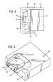
- FIG. 4 is a front view, to an enlarged scale, showing the engagement of the hard disc drive with the hard disc drive cage;
- FIG. 5 is a schematic cut-away perspective view of a circuit housing incorporating the hard disc drive cage.
- FIG. 1 is a perspective view showing a hard disc drive cage 1 and a hard disc drive 2 positioned for insertion into the cage 1 .
- the hard disc drive 2 comprises a housing 3 and a mounting bracket 4 attached to the housing.
- the mounting bracket 4 comprises a pair of side runners 5 extending along the sides of the housing 3 , and a cross-piece 6 which extends across the end of the housing 3 between the side runners 5 .
- the cross piece 6 includes a release lever 7 and a finger recess 8 , whose purposes will be described in detail later.
- Hard disc drive manufacturers produce hard disc drives with housings 3 having standardised dimensions, and thus the mounting bracket 4 may be provided with attachment points such as bolt holes 9 for attaching the mounting bracket 4 to any available hard disc drive housing 3 .
- the disc drive cage 1 for receiving the disc drive 2 and mounting bracket 4 comprises a pair of sidewalls 10 and a perforated top 11 formed with an array of ventilation holes 12 .
- the cage 1 is formed from a metallic sheet by performing bending, stamping or folding operations on a sheet metal blank.
- the cage 1 is formed from one millimetre thick zinc plated mild steel, but other metals such as aluminum may be used, for example, for weight reduction.
- the cage may be formed from plastics or composite material with a metallic coating on its inside or outside surface to provide electromagnetic shielding.
- a plastics material with an embedded metallic layer or mesh may be used.
- the ventilation holes 12 are circular, and of about 3 to 8 mm diameter. In the illustrated embodiment the largest dimension of any hole formed in the sheet metal of the cage is about 6 mm. To minimise electromagnetic leakage, all openings are made to be substantially circular or rounded. If the holes are too small, they present too great a resistance to air flow for effective cooling. If the holes are elongated, then their electromagnetic shielding effect is compromised. Circular holes of from about 5 to about 6 mm diameter have been found to be effective.
- the hard disc drive cage 1 has an open front 13 , through which the hard disc drive 2 and mounting bracket 4 are inserted.
- the sidewalls 10 at their ends adjacent the open front 13 , have inwardly-projecting feet 14 extending from their lower edges.
- the feet 14 are provided with openings 15 for fixing the cage 1 to a supporting structure or housing 16 .
- each of the sidewalls 10 are bent to form an inwardly-extending step 17 which connects the sidewall 10 to a riser 18 .
- the riser 18 extends vertically downwardly from the inner edge of the step 17 , and from the lower edge of the riser 18 a base 19 extends inwardly.
- the base 19 is coplanar with the foot 14 and extends to the rear of the cage 1 .
- the bases 19 and feet 14 of the respective sidewalls 10 may be extended to meet each other to form a bottom wall for the cage 1 , in order completely to enclose the hard disc drive 2 .
- the rear face of the cage 1 is closed by a rear wall, optionally also provided with ventilation holes.
- the rear wall also provides a mounting for an electrical connection to the hard disc drive 2 when installed in the cage 1 .
- the cage 1 is so dimensioned that the side runners 5 of the mounting bracket 4 engage the steps 17 of the cage 1 with their undersurfaces as the hard disc drive 2 is inserted into the cage 1 .
- the sidewalls 10 are provided with inwardly-embossed openings 20 spaced above the step 17 on each side, the embossments around the openings being engageable with the upper surfaces of the side runners 5 to retain them on the steps 17 .
- a further inward embossment 21 of the sidewalls 10 is provided at the mid height between the step 17 and the embossed openings 20 , at the front and rear of the cage 1 .
- the purpose of the embossments 21 is to provide an effective earth contact with earthing strips 22 provided on the outside faces of the side runners 5 of the mounting bracket 4 .
- the embodiments 21 may therefore be provided at any suitable location to contact the earthing strips 22 when the disc drive is mounted within the cage.
- the cage 1 is attached to the base 23 of a housing 16 , for example by the use of threaded fasteners such as screws extending through the mounting holes 15 in the feet 14 of the cage 1 .
- the front face 24 of the housing 16 is provided with an opening corresponding in size to the open front face 13 of the cage 1 , and through which a drive assembly comprising a hard disc drive 2 and a mounting bracket 4 may be inserted.
- the drive is mounted to the cage by aligning the drive assembly and the cage as shown in FIG. 1, and moving the drive assembly into the cage so that the side runners 5 rest on the steps 17 of the sidewalls 10 of the cage 1 .
- earthing strips 22 on the side runners 5 make firm engagement with the embossments 21 in the side walls 10
- the embossed openings in the sidewalls 10 engage the upper surface of the side runners 5 .
- the upper surfaces of the side runners. 5 are provided with resilient detents 25 which are deflected downwardly as they pass beneath the embossed openings 20 , and subsequently resiliently recover to secure the side runner 5 in its longitudinal direction.
- the detent 25 adjacent the cross piece 6 is positioned between the two embossed openings 20 nearest the open front 13 of the cage 1 , while the detent 25 remote from the cross piece 6 of the mounting bracket 4 is positioned behind the embossed opening 20 adjacent the rear face of the cage 1 .
- a connection such as a multi-pin plug or socket is mounted to a rear wall of the cage 1 , and a mating connector positioned on the end surface of the hard drive housing 3 remote from the cross piece 6 engages with the connection of the cage 1 during the final insertion movement of the hard drive assembly.
- an operator engages the finger recess 8 and pulls a release lever 7 away from the cross piece 6 .
- This causes the release lever 7 to be pivoted about a vertical axis and engage a front edge of the side wall 10 .
- the levering action then moves the hard drive assembly out of the cage 1 by an initial amount, resiliently compressing the detents 25 so that they pass beneath their respective embossed openings 20 and releasing the electrical connections at the rear face of the cage 1 .
- the operator may grasp the housing 3 of the hard drive 2 in order to draw the hard drive assembly completely out of the cage 1 .
- cage 1 has been described in relation to a mounting for a hard disc drive unit, it will be understood that any other removable assembly equipped with side runners may be used with a cage 1 according to the present invention.
- Alternative units such as floppy disc drives, card drives, or other ancillary devices may therefore be simply mounted and dismounted from an electronic circuit while conserving the integrity of the electromagnetic shielding provided for the circuit.
Abstract
Description
Claims (14)
Priority Applications (1)
| Application Number | Priority Date | Filing Date | Title |
|---|---|---|---|
| US10/217,157 US6661677B1 (en) | 2002-08-12 | 2002-08-12 | Disc drive cage |
Applications Claiming Priority (1)
| Application Number | Priority Date | Filing Date | Title |
|---|---|---|---|
| US10/217,157 US6661677B1 (en) | 2002-08-12 | 2002-08-12 | Disc drive cage |
Publications (1)
| Publication Number | Publication Date |
|---|---|
| US6661677B1 true US6661677B1 (en) | 2003-12-09 |
Family
ID=29711545
Family Applications (1)
| Application Number | Title | Priority Date | Filing Date |
|---|---|---|---|
| US10/217,157 Expired - Lifetime US6661677B1 (en) | 2002-08-12 | 2002-08-12 | Disc drive cage |
Country Status (1)
| Country | Link |
|---|---|
| US (1) | US6661677B1 (en) |
Cited By (28)
| Publication number | Priority date | Publication date | Assignee | Title |
|---|---|---|---|---|
| US20040192112A1 (en) * | 2003-03-27 | 2004-09-30 | Nec Corporation | Housing of electronic apparatus |
| US20040231876A1 (en) * | 2003-05-24 | 2004-11-25 | Zhang Xiao Ling | Optical disc driver enclosure |
| US20050044358A1 (en) * | 2003-08-20 | 2005-02-24 | Steve Anspach | Deployable secure communication system |
| US20050058122A1 (en) * | 2003-09-15 | 2005-03-17 | Anspach Steve S. | Standard telephone equipment (STE) based deployable secure communication system |
| US20050060543A1 (en) * | 2003-09-15 | 2005-03-17 | Steve Anspach | Encryption of voice and data in a single data stream in a deployable, secure communication system |
| US20050135075A1 (en) * | 2003-12-23 | 2005-06-23 | E. Com Compucase Co., Ltd. | Computer case and parts thereof |
| US20050134155A1 (en) * | 2003-09-23 | 2005-06-23 | Anspach Steven S. | Encryption unit quick insert/ quick removal housing |
| US20050190535A1 (en) * | 2004-02-27 | 2005-09-01 | Hon Hai Precision Industry Co., Ltd. | Fastening device for data storage devices |
| US20050211459A1 (en) * | 2004-03-25 | 2005-09-29 | Asustek Computer Inc. | Electronic device and holder having elastic elements thereof |
| US20050259390A1 (en) * | 2004-05-18 | 2005-11-24 | Tatung Co., Ltd. | Latch hook structure of removable storage devices |
| US20050278936A1 (en) * | 2004-06-18 | 2005-12-22 | Nikolaus Schunk | Optoelectronic apparatus with a shielding cage, and methods for production of an optoelectronic apparatus with a shielding cage. |
| US7099158B1 (en) * | 2003-02-13 | 2006-08-29 | Bellsouth Intellectual Property Corp. | Housing for modules |
| US20060285287A1 (en) * | 2005-06-17 | 2006-12-21 | Hsuan-Chen Chen | Protecting apparatus for storage device |
| US20070127206A1 (en) * | 2005-12-01 | 2007-06-07 | Xyratex Technology Limited | Data storage device carrier and carrier tray |
| US20070177578A1 (en) * | 2005-01-11 | 2007-08-02 | Anspach Steven S | Standard telephone equipment (STE) based deployable secure cellular communication system |
| US20070194021A1 (en) * | 2006-02-22 | 2007-08-23 | Chien-Fa Liang | Modular case assembly device |
| US20090077375A1 (en) * | 2003-09-15 | 2009-03-19 | Steve Anspach | Encapsulation of secure encrypted data in a deployable, secure communication system allowing benign, secure commercial transport |
| US7533259B2 (en) | 2003-09-15 | 2009-05-12 | Telecommunication Systems, Inc. | Encapsulation of secure encrypted data in a deployable, secure communication system allowing benign, secure commercial transport |
| US20090213491A1 (en) * | 2008-02-22 | 2009-08-27 | Western Digital Technologies, Inc. | Information storage device with a bridge controller and a plurality of electrically coupled conductive shields |
| US20100067344A1 (en) * | 2008-09-15 | 2010-03-18 | Western Digital Technologies, Inc. | Information storage device having a disk drive and a bridge controller pcb within a monolithic conductive nest |
| US7701705B1 (en) | 2007-12-10 | 2010-04-20 | Western Digital Technologies, Inc. | Information storage device with sheet metal projections and elastomeric inserts |
| US20100243312A1 (en) * | 2009-03-30 | 2010-09-30 | Lockheed Martin Corporation | Equipment container retention and bonding system and method |
| US20110043993A1 (en) * | 2009-08-21 | 2011-02-24 | Hong Fu Jin Precision Industry (Shenzhen) Co., Ltd | Mounting apparatus for data storage device |
| US8164849B1 (en) | 2007-12-10 | 2012-04-24 | Western Digital Technologies, Inc. | Information storage device with a conductive shield having free and forced heat convection configurations |
| US20120117289A1 (en) * | 2010-11-09 | 2012-05-10 | Michael Morgan | Adaptable Storage Cartridge System |
| US8390952B1 (en) | 2008-02-22 | 2013-03-05 | Western Digital Technologies, Inc. | Information storage device having a conductive shield with a peripheral capacitive flange |
| US9386719B2 (en) * | 2014-10-27 | 2016-07-05 | Cremax Tech Co., Ltd. | Fixing structure applicable to multiple sizes of storage device |
| US9514310B2 (en) | 2013-05-09 | 2016-12-06 | Telecommunication Systems, Inc. | Gap services router (GSR) |
Citations (20)
| Publication number | Priority date | Publication date | Assignee | Title |
|---|---|---|---|---|
| US5226828A (en) | 1991-09-23 | 1993-07-13 | Siemens Aktiengesellschaft | Device for unlocking a resiliently prestressed catch element at the side of an insert unit |
| JPH07220464A (en) | 1993-12-28 | 1995-08-18 | Hewlett Packard Co <Hp> | Electronic system using memory that can be exchanged |
| US5510955A (en) * | 1993-01-04 | 1996-04-23 | Samsung Electronics Co., Ltd. | Cage in computer equipment for locking peripheral equipment therewithin using hooked lockpins |
| EP0713219A2 (en) | 1994-11-15 | 1996-05-22 | Tandberg Data Storage As | Tape drive with floating support for insert |
| US5564804A (en) * | 1993-12-17 | 1996-10-15 | Silicon Graphics, Inc. | Disk drive bracket |
| US5572402A (en) | 1994-02-02 | 1996-11-05 | Samsung Electronics Co., Ltd. | Hard disk drive mounting assembly for a computer |
| US5588728A (en) * | 1994-11-29 | 1996-12-31 | Intel Corporation | Portable disk drive carrier and chassis |
| US5652695A (en) * | 1995-05-05 | 1997-07-29 | Dell Usa, L.P. | Hard drive carrier design permitting floating retention of a connector assembly to facilitate blind mating of the connector assembly in a hard drive bay |
| US5673171A (en) * | 1995-12-05 | 1997-09-30 | Compaq Computer Corporation | Hard disc drive support tray apparatus with built-in handling shock reduction, EMI shielding and mounting alignment structures |
| US5673172A (en) * | 1996-01-05 | 1997-09-30 | Compaq Computer Corporation | Apparatus for electromagnetic interference and electrostatic discharge shielding of hot plug-connected hard disk drives |
| US5726864A (en) * | 1995-08-24 | 1998-03-10 | Digital Equipment Corporation | Cage system |
| US5751551A (en) | 1995-11-07 | 1998-05-12 | Sun Microsystems, Inc. | Universal hard drive bracket with shock and vibrational isolation and electrical grounding |
| US5940265A (en) * | 1997-07-22 | 1999-08-17 | Ho; Hsin Chien | Diskdrive suspending device for a computer |
| JPH11348675A (en) | 1998-06-09 | 1999-12-21 | Matsushita Electric Ind Co Ltd | On-vehicle acoustic device |
| US6061232A (en) | 1997-10-31 | 2000-05-09 | Ho; Ming-Chiao | Supporting bracket assembly for drawer-type hard-disk drive |
| US6067225A (en) | 1997-08-04 | 2000-05-23 | Sun Microsystems, Inc. | Disk drive bracket |
| US6088222A (en) | 1996-11-14 | 2000-07-11 | Dell Usa, L.P. | Computer peripheral chassis frame structure having a split lance for location, electrical grounding, and load bearing of chassis carriers |
| US6185097B1 (en) * | 1997-09-10 | 2001-02-06 | Inclose Design, Inc. | Convectively cooled memory storage device housing |
| US6373707B1 (en) | 2000-06-02 | 2002-04-16 | Astec International Limited | Module mounting slide clamp mechanism |
| US6421236B1 (en) | 2000-08-07 | 2002-07-16 | Intel Corporation | Hot swap disk drive carrier and disk drive bay |
-
2002
- 2002-08-12 US US10/217,157 patent/US6661677B1/en not_active Expired - Lifetime
Patent Citations (20)
| Publication number | Priority date | Publication date | Assignee | Title |
|---|---|---|---|---|
| US5226828A (en) | 1991-09-23 | 1993-07-13 | Siemens Aktiengesellschaft | Device for unlocking a resiliently prestressed catch element at the side of an insert unit |
| US5510955A (en) * | 1993-01-04 | 1996-04-23 | Samsung Electronics Co., Ltd. | Cage in computer equipment for locking peripheral equipment therewithin using hooked lockpins |
| US5564804A (en) * | 1993-12-17 | 1996-10-15 | Silicon Graphics, Inc. | Disk drive bracket |
| JPH07220464A (en) | 1993-12-28 | 1995-08-18 | Hewlett Packard Co <Hp> | Electronic system using memory that can be exchanged |
| US5572402A (en) | 1994-02-02 | 1996-11-05 | Samsung Electronics Co., Ltd. | Hard disk drive mounting assembly for a computer |
| EP0713219A2 (en) | 1994-11-15 | 1996-05-22 | Tandberg Data Storage As | Tape drive with floating support for insert |
| US5588728A (en) * | 1994-11-29 | 1996-12-31 | Intel Corporation | Portable disk drive carrier and chassis |
| US5652695A (en) * | 1995-05-05 | 1997-07-29 | Dell Usa, L.P. | Hard drive carrier design permitting floating retention of a connector assembly to facilitate blind mating of the connector assembly in a hard drive bay |
| US5726864A (en) * | 1995-08-24 | 1998-03-10 | Digital Equipment Corporation | Cage system |
| US5751551A (en) | 1995-11-07 | 1998-05-12 | Sun Microsystems, Inc. | Universal hard drive bracket with shock and vibrational isolation and electrical grounding |
| US5673171A (en) * | 1995-12-05 | 1997-09-30 | Compaq Computer Corporation | Hard disc drive support tray apparatus with built-in handling shock reduction, EMI shielding and mounting alignment structures |
| US5673172A (en) * | 1996-01-05 | 1997-09-30 | Compaq Computer Corporation | Apparatus for electromagnetic interference and electrostatic discharge shielding of hot plug-connected hard disk drives |
| US6088222A (en) | 1996-11-14 | 2000-07-11 | Dell Usa, L.P. | Computer peripheral chassis frame structure having a split lance for location, electrical grounding, and load bearing of chassis carriers |
| US5940265A (en) * | 1997-07-22 | 1999-08-17 | Ho; Hsin Chien | Diskdrive suspending device for a computer |
| US6067225A (en) | 1997-08-04 | 2000-05-23 | Sun Microsystems, Inc. | Disk drive bracket |
| US6185097B1 (en) * | 1997-09-10 | 2001-02-06 | Inclose Design, Inc. | Convectively cooled memory storage device housing |
| US6061232A (en) | 1997-10-31 | 2000-05-09 | Ho; Ming-Chiao | Supporting bracket assembly for drawer-type hard-disk drive |
| JPH11348675A (en) | 1998-06-09 | 1999-12-21 | Matsushita Electric Ind Co Ltd | On-vehicle acoustic device |
| US6373707B1 (en) | 2000-06-02 | 2002-04-16 | Astec International Limited | Module mounting slide clamp mechanism |
| US6421236B1 (en) | 2000-08-07 | 2002-07-16 | Intel Corporation | Hot swap disk drive carrier and disk drive bay |
Cited By (50)
| Publication number | Priority date | Publication date | Assignee | Title |
|---|---|---|---|---|
| US7099158B1 (en) * | 2003-02-13 | 2006-08-29 | Bellsouth Intellectual Property Corp. | Housing for modules |
| US20040192112A1 (en) * | 2003-03-27 | 2004-09-30 | Nec Corporation | Housing of electronic apparatus |
| US6908338B2 (en) * | 2003-03-27 | 2005-06-21 | Nec Corporation | Housing of electronic apparatus |
| US20040231876A1 (en) * | 2003-05-24 | 2004-11-25 | Zhang Xiao Ling | Optical disc driver enclosure |
| US6909047B2 (en) * | 2003-05-24 | 2005-06-21 | Hon Hai Precision Ind. Co., Ltd. | Optical disc driver enclosure |
| US20050044358A1 (en) * | 2003-08-20 | 2005-02-24 | Steve Anspach | Deployable secure communication system |
| US20090313469A1 (en) * | 2003-08-20 | 2009-12-17 | Steve Anspach | Deployable secure communication system |
| US7577835B2 (en) | 2003-08-20 | 2009-08-18 | Telecommunication Systems, Inc. | Deployable secure communication system |
| US8090941B2 (en) | 2003-08-20 | 2012-01-03 | Telecommunication Systems, Inc. | Deployable secure communication system |
| US8958416B2 (en) | 2003-09-15 | 2015-02-17 | Telecommunication Systems, Inc. | Standard telephone equipment (STE) based deployable secure communication system |
| US7533259B2 (en) | 2003-09-15 | 2009-05-12 | Telecommunication Systems, Inc. | Encapsulation of secure encrypted data in a deployable, secure communication system allowing benign, secure commercial transport |
| US20050058122A1 (en) * | 2003-09-15 | 2005-03-17 | Anspach Steve S. | Standard telephone equipment (STE) based deployable secure communication system |
| US20100067696A1 (en) * | 2003-09-15 | 2010-03-18 | Anspach Steve S | Standard telephone equipment (STE) based deployable secure communication system |
| US7626977B2 (en) | 2003-09-15 | 2009-12-01 | Telecommunication Systems, Inc. | Standard telephone equipment (STE) based deployable secure communication system |
| US7707407B2 (en) | 2003-09-15 | 2010-04-27 | Telecommunication Systems, Inc. | Encryption of voice and data in a single data stream in a deployable, secure communication system |
| US20050060543A1 (en) * | 2003-09-15 | 2005-03-17 | Steve Anspach | Encryption of voice and data in a single data stream in a deployable, secure communication system |
| US8850179B2 (en) | 2003-09-15 | 2014-09-30 | Telecommunication Systems, Inc. | Encapsulation of secure encrypted data in a deployable, secure communication system allowing benign, secure commercial transport |
| US8295273B2 (en) | 2003-09-15 | 2012-10-23 | Telecommunication Systems, Inc. | Standard telephone equipment (STE) based deployable secure communication system |
| US8209750B2 (en) | 2003-09-15 | 2012-06-26 | Telecommunication Systems, Inc. | Encryption of voice and data in a single data stream in a deployable, secure communication system |
| US20090077375A1 (en) * | 2003-09-15 | 2009-03-19 | Steve Anspach | Encapsulation of secure encrypted data in a deployable, secure communication system allowing benign, secure commercial transport |
| US20100202615A1 (en) * | 2003-09-15 | 2010-08-12 | Steve Anspach | Encryption of voice and data in a single data stream in a deployable,secure communication system |
| US20050134155A1 (en) * | 2003-09-23 | 2005-06-23 | Anspach Steven S. | Encryption unit quick insert/ quick removal housing |
| US20050135075A1 (en) * | 2003-12-23 | 2005-06-23 | E. Com Compucase Co., Ltd. | Computer case and parts thereof |
| US7085131B2 (en) * | 2004-02-27 | 2006-08-01 | Hon Hai Precision Industry Co., Ltd. | Fastening device for data storage devices |
| US20050190535A1 (en) * | 2004-02-27 | 2005-09-01 | Hon Hai Precision Industry Co., Ltd. | Fastening device for data storage devices |
| US20050211459A1 (en) * | 2004-03-25 | 2005-09-29 | Asustek Computer Inc. | Electronic device and holder having elastic elements thereof |
| US7148418B2 (en) * | 2004-03-25 | 2006-12-12 | Asustek Computer Inc. | Electronic device and holder having elastic elements thereof |
| US20050259390A1 (en) * | 2004-05-18 | 2005-11-24 | Tatung Co., Ltd. | Latch hook structure of removable storage devices |
| US20050278936A1 (en) * | 2004-06-18 | 2005-12-22 | Nikolaus Schunk | Optoelectronic apparatus with a shielding cage, and methods for production of an optoelectronic apparatus with a shielding cage. |
| US20070177578A1 (en) * | 2005-01-11 | 2007-08-02 | Anspach Steven S | Standard telephone equipment (STE) based deployable secure cellular communication system |
| US20060285287A1 (en) * | 2005-06-17 | 2006-12-21 | Hsuan-Chen Chen | Protecting apparatus for storage device |
| US20070127206A1 (en) * | 2005-12-01 | 2007-06-07 | Xyratex Technology Limited | Data storage device carrier and carrier tray |
| US7447011B2 (en) * | 2005-12-01 | 2008-11-04 | Xyratex Technology Limited | Data storage device carrier and carrier tray |
| US20070194021A1 (en) * | 2006-02-22 | 2007-08-23 | Chien-Fa Liang | Modular case assembly device |
| US7735669B2 (en) * | 2006-02-22 | 2010-06-15 | Super Micro Computer Inc. | Modular case assembly device |
| US7701705B1 (en) | 2007-12-10 | 2010-04-20 | Western Digital Technologies, Inc. | Information storage device with sheet metal projections and elastomeric inserts |
| US8164849B1 (en) | 2007-12-10 | 2012-04-24 | Western Digital Technologies, Inc. | Information storage device with a conductive shield having free and forced heat convection configurations |
| US8004791B2 (en) | 2008-02-22 | 2011-08-23 | Western Digital Technologies, Inc. | Information storage device with a bridge controller and a plurality of electrically coupled conductive shields |
| US20090213491A1 (en) * | 2008-02-22 | 2009-08-27 | Western Digital Technologies, Inc. | Information storage device with a bridge controller and a plurality of electrically coupled conductive shields |
| US8390952B1 (en) | 2008-02-22 | 2013-03-05 | Western Digital Technologies, Inc. | Information storage device having a conductive shield with a peripheral capacitive flange |
| US20100067344A1 (en) * | 2008-09-15 | 2010-03-18 | Western Digital Technologies, Inc. | Information storage device having a disk drive and a bridge controller pcb within a monolithic conductive nest |
| US7940491B2 (en) | 2008-09-15 | 2011-05-10 | Western Digital Technologies, Inc. | Information storage device having a disk drive and a bridge controller PCB within a monolithic conductive nest |
| US20100243312A1 (en) * | 2009-03-30 | 2010-09-30 | Lockheed Martin Corporation | Equipment container retention and bonding system and method |
| US8053683B2 (en) * | 2009-03-30 | 2011-11-08 | Lockheed Martin Corporation | Equipment container retention and bonding system and method |
| US8289696B2 (en) * | 2009-08-21 | 2012-10-16 | Hong Fu Jin Precision Industry (Shenzhen) Co., Ltd. | Mounting apparatus for data storage device |
| US20110043993A1 (en) * | 2009-08-21 | 2011-02-24 | Hong Fu Jin Precision Industry (Shenzhen) Co., Ltd | Mounting apparatus for data storage device |
| US20120117289A1 (en) * | 2010-11-09 | 2012-05-10 | Michael Morgan | Adaptable Storage Cartridge System |
| US8793413B2 (en) * | 2010-11-09 | 2014-07-29 | Seagate Technology Llc | Adaptable storage cartridge system |
| US9514310B2 (en) | 2013-05-09 | 2016-12-06 | Telecommunication Systems, Inc. | Gap services router (GSR) |
| US9386719B2 (en) * | 2014-10-27 | 2016-07-05 | Cremax Tech Co., Ltd. | Fixing structure applicable to multiple sizes of storage device |
Similar Documents
| Publication | Publication Date | Title |
|---|---|---|
| US6661677B1 (en) | Disc drive cage | |
| US7903431B2 (en) | Electromagnetic interference shielding apparatus | |
| US6239359B1 (en) | Circuit board RF shielding | |
| US7663895B2 (en) | Electromagnetic shielding device for printed circuit board | |
| US7772505B2 (en) | Electromagnetic interference (EMI) shielding apparatus and related methods | |
| US5978212A (en) | Disk drive locking member with handle | |
| EP2435890A2 (en) | Microtca device | |
| US20090310312A1 (en) | Apparatus for mounting a module and enabling heat conduction from the module to the mounting surface | |
| US6937475B2 (en) | Mounting and grounding assembly for circuit board mounted parallel to chassis bottom | |
| US6239984B1 (en) | Backplane circuit board for an electronic chassis | |
| CN206100791U (en) | Frame, board cascade screen spare and electron device of electromagnetic interference EMI shielding part | |
| US5742003A (en) | Computer terminal box with improved grounding structure | |
| US20060084318A1 (en) | Double-side mounting electrical connector | |
| US10750632B1 (en) | Mounting system for component rack | |
| US6870093B2 (en) | Adaptable EMI/RFI shielding for a front-panel attachment to an enclosure | |
| KR100286396B1 (en) | Shielded module support structure | |
| US6189848B1 (en) | Fastener with integral spring clip | |
| AU698965B2 (en) | Module support structure | |
| CN218269600U (en) | Gas water heater shell with improved connection mode | |
| US7102897B2 (en) | Circuit board module, circuit board chassis and electromagnetic shielding plate therefor | |
| JP4497509B2 (en) | Rack mountable equipment storage box | |
| CN218158297U (en) | Automatically controlled box convenient to detect junction part | |
| CN220586599U (en) | Fixing structure of power panel and maintenance cover and household appliance | |
| CN217151071U (en) | Skirting line | |
| CN216700765U (en) | Air-cooled case |
Legal Events
| Date | Code | Title | Description |
|---|---|---|---|
| AS | Assignment |
Owner name: SUN MICROSYSTEMS, INC., CALIFORNIA Free format text: ASSIGNMENT OF ASSIGNORS INTEREST;ASSIGNORS:RUMNEY, GARY;SUN MICROSYSTEMS LIMITED;REEL/FRAME:014267/0514 Effective date: 20020811 |
|
| STCF | Information on status: patent grant |
Free format text: PATENTED CASE |
|
| CC | Certificate of correction | ||
| FPAY | Fee payment |
Year of fee payment: 4 |
|
| FPAY | Fee payment |
Year of fee payment: 8 |
|
| FPAY | Fee payment |
Year of fee payment: 12 |
|
| AS | Assignment |
Owner name: ORACLE AMERICA, INC., CALIFORNIA Free format text: MERGER AND CHANGE OF NAME;ASSIGNORS:ORACLE USA, INC.;SUN MICROSYSTEMS, INC.;ORACLE AMERICA, INC.;REEL/FRAME:037278/0746 Effective date: 20100212 |