US6662898B1 - Tire side slip angle control for an automotive vehicle using steering actuators - Google Patents
Tire side slip angle control for an automotive vehicle using steering actuators Download PDFInfo
- Publication number
- US6662898B1 US6662898B1 US10/065,424 US6542402A US6662898B1 US 6662898 B1 US6662898 B1 US 6662898B1 US 6542402 A US6542402 A US 6542402A US 6662898 B1 US6662898 B1 US 6662898B1
- Authority
- US
- United States
- Prior art keywords
- slip angle
- angle
- steering
- actuator
- recited
- Prior art date
- Legal status (The legal status is an assumption and is not a legal conclusion. Google has not performed a legal analysis and makes no representation as to the accuracy of the status listed.)
- Expired - Lifetime
Links
Images


Classifications
-
- B—PERFORMING OPERATIONS; TRANSPORTING
- B60—VEHICLES IN GENERAL
- B60G—VEHICLE SUSPENSION ARRANGEMENTS
- B60G17/00—Resilient suspensions having means for adjusting the spring or vibration-damper characteristics, for regulating the distance between a supporting surface and a sprung part of vehicle or for locking suspension during use to meet varying vehicular or surface conditions, e.g. due to speed or load
- B60G17/015—Resilient suspensions having means for adjusting the spring or vibration-damper characteristics, for regulating the distance between a supporting surface and a sprung part of vehicle or for locking suspension during use to meet varying vehicular or surface conditions, e.g. due to speed or load the regulating means comprising electric or electronic elements
- B60G17/0195—Resilient suspensions having means for adjusting the spring or vibration-damper characteristics, for regulating the distance between a supporting surface and a sprung part of vehicle or for locking suspension during use to meet varying vehicular or surface conditions, e.g. due to speed or load the regulating means comprising electric or electronic elements characterised by the regulation being combined with other vehicle control systems
-
- B—PERFORMING OPERATIONS; TRANSPORTING
- B62—LAND VEHICLES FOR TRAVELLING OTHERWISE THAN ON RAILS
- B62D—MOTOR VEHICLES; TRAILERS
- B62D6/00—Arrangements for automatically controlling steering depending on driving conditions sensed and responded to, e.g. control circuits
- B62D6/04—Arrangements for automatically controlling steering depending on driving conditions sensed and responded to, e.g. control circuits responsive only to forces disturbing the intended course of the vehicle, e.g. forces acting transversely to the direction of vehicle travel
-
- B—PERFORMING OPERATIONS; TRANSPORTING
- B60—VEHICLES IN GENERAL
- B60G—VEHICLE SUSPENSION ARRANGEMENTS
- B60G2400/00—Indexing codes relating to detected, measured or calculated conditions or factors
- B60G2400/05—Attitude
- B60G2400/052—Angular rate
- B60G2400/0521—Roll rate
-
- B—PERFORMING OPERATIONS; TRANSPORTING
- B60—VEHICLES IN GENERAL
- B60G—VEHICLE SUSPENSION ARRANGEMENTS
- B60G2400/00—Indexing codes relating to detected, measured or calculated conditions or factors
- B60G2400/05—Attitude
- B60G2400/052—Angular rate
- B60G2400/0522—Pitch rate
-
- B—PERFORMING OPERATIONS; TRANSPORTING
- B60—VEHICLES IN GENERAL
- B60G—VEHICLE SUSPENSION ARRANGEMENTS
- B60G2400/00—Indexing codes relating to detected, measured or calculated conditions or factors
- B60G2400/05—Attitude
- B60G2400/052—Angular rate
- B60G2400/0523—Yaw rate
-
- B—PERFORMING OPERATIONS; TRANSPORTING
- B60—VEHICLES IN GENERAL
- B60G—VEHICLE SUSPENSION ARRANGEMENTS
- B60G2400/00—Indexing codes relating to detected, measured or calculated conditions or factors
- B60G2400/10—Acceleration; Deceleration
- B60G2400/104—Acceleration; Deceleration lateral or transversal with regard to vehicle
-
- B—PERFORMING OPERATIONS; TRANSPORTING
- B60—VEHICLES IN GENERAL
- B60G—VEHICLE SUSPENSION ARRANGEMENTS
- B60G2400/00—Indexing codes relating to detected, measured or calculated conditions or factors
- B60G2400/10—Acceleration; Deceleration
- B60G2400/106—Acceleration; Deceleration longitudinal with regard to vehicle, e.g. braking
-
- B—PERFORMING OPERATIONS; TRANSPORTING
- B60—VEHICLES IN GENERAL
- B60G—VEHICLE SUSPENSION ARRANGEMENTS
- B60G2400/00—Indexing codes relating to detected, measured or calculated conditions or factors
- B60G2400/20—Speed
- B60G2400/204—Vehicle speed
-
- B—PERFORMING OPERATIONS; TRANSPORTING
- B60—VEHICLES IN GENERAL
- B60G—VEHICLE SUSPENSION ARRANGEMENTS
- B60G2400/00—Indexing codes relating to detected, measured or calculated conditions or factors
- B60G2400/40—Steering conditions
- B60G2400/41—Steering angle
-
- B—PERFORMING OPERATIONS; TRANSPORTING
- B60—VEHICLES IN GENERAL
- B60G—VEHICLE SUSPENSION ARRANGEMENTS
- B60G2400/00—Indexing codes relating to detected, measured or calculated conditions or factors
- B60G2400/40—Steering conditions
- B60G2400/41—Steering angle
- B60G2400/412—Steering angle of steering wheel or column
-
- B—PERFORMING OPERATIONS; TRANSPORTING
- B60—VEHICLES IN GENERAL
- B60G—VEHICLE SUSPENSION ARRANGEMENTS
- B60G2400/00—Indexing codes relating to detected, measured or calculated conditions or factors
- B60G2400/80—Exterior conditions
- B60G2400/82—Ground surface
- B60G2400/822—Road friction coefficient determination affecting wheel traction
-
- B—PERFORMING OPERATIONS; TRANSPORTING
- B60—VEHICLES IN GENERAL
- B60G—VEHICLE SUSPENSION ARRANGEMENTS
- B60G2800/00—Indexing codes relating to the type of movement or to the condition of the vehicle and to the end result to be achieved by the control action
- B60G2800/21—Traction, slip, skid or slide control
- B60G2800/212—Transversal; Side-slip during cornering
-
- B—PERFORMING OPERATIONS; TRANSPORTING
- B60—VEHICLES IN GENERAL
- B60G—VEHICLE SUSPENSION ARRANGEMENTS
- B60G2800/00—Indexing codes relating to the type of movement or to the condition of the vehicle and to the end result to be achieved by the control action
- B60G2800/21—Traction, slip, skid or slide control
- B60G2800/215—Traction, slip, skid or slide control by applying a braking action on each wheel individually
-
- B—PERFORMING OPERATIONS; TRANSPORTING
- B60—VEHICLES IN GENERAL
- B60G—VEHICLE SUSPENSION ARRANGEMENTS
- B60G2800/00—Indexing codes relating to the type of movement or to the condition of the vehicle and to the end result to be achieved by the control action
- B60G2800/24—Steering, cornering
- B60G2800/244—Oversteer
-
- B—PERFORMING OPERATIONS; TRANSPORTING
- B60—VEHICLES IN GENERAL
- B60G—VEHICLE SUSPENSION ARRANGEMENTS
- B60G2800/00—Indexing codes relating to the type of movement or to the condition of the vehicle and to the end result to be achieved by the control action
- B60G2800/70—Estimating or calculating vehicle parameters or state variables
- B60G2800/702—Improving accuracy of a sensor signal
-
- B—PERFORMING OPERATIONS; TRANSPORTING
- B60—VEHICLES IN GENERAL
- B60G—VEHICLE SUSPENSION ARRANGEMENTS
- B60G2800/00—Indexing codes relating to the type of movement or to the condition of the vehicle and to the end result to be achieved by the control action
- B60G2800/90—System Controller type
- B60G2800/92—ABS - Brake Control
-
- B—PERFORMING OPERATIONS; TRANSPORTING
- B60—VEHICLES IN GENERAL
- B60G—VEHICLE SUSPENSION ARRANGEMENTS
- B60G2800/00—Indexing codes relating to the type of movement or to the condition of the vehicle and to the end result to be achieved by the control action
- B60G2800/90—System Controller type
- B60G2800/96—ASC - Assisted or power Steering control
-
- B—PERFORMING OPERATIONS; TRANSPORTING
- B60—VEHICLES IN GENERAL
- B60T—VEHICLE BRAKE CONTROL SYSTEMS OR PARTS THEREOF; BRAKE CONTROL SYSTEMS OR PARTS THEREOF, IN GENERAL; ARRANGEMENT OF BRAKING ELEMENTS ON VEHICLES IN GENERAL; PORTABLE DEVICES FOR PREVENTING UNWANTED MOVEMENT OF VEHICLES; VEHICLE MODIFICATIONS TO FACILITATE COOLING OF BRAKES
- B60T2260/00—Interaction of vehicle brake system with other systems
- B60T2260/02—Active Steering, Steer-by-Wire
- B60T2260/022—Rear-wheel steering; Four-wheel steering
Definitions
- the present invention relates generally to a dynamic behavior control apparatus for an automotive vehicle, and more specifically, to a method and apparatus for controlling the tire side slip angle of the vehicle by controlling the road wheel steering direction of the vehicle.
- Dynamic control systems for automotive vehicles have recently begun to be offered on various products.
- Antilock braking systems (ABS) and traction control (TC) control tire slip ratios.
- Other dynamic control systems control the side slip angle and yaw response of the vehicle by controlling the tractive forces and/or braking torque at the various wheels of the vehicle.
- Side slip and yaw control systems typically compare the desired direction, yaw response and lateral acceleration of the vehicle based upon the steering wheel angle, speed, and the direction of travel to an ideal (stable) vehicle model. By regulating the amount of braking torque and tractive friction at each corner of the vehicle, the desired path of travel and yaw rate may be maintained.
- a large lateral slip angle can occur at the front wheels during severe understeer and oversteer events.
- the lateral force generated from a tire typically reaches a maximum value F latmax the slip angle referred to as the slip angle at peak lateral force.
- the maximum lateral force then decreases or levels off as the slip angle increases further.
- the leveling off is commonly referred to as the saturation region.
- One problem with using brake effort to control the lateral dynamics and response of the vehicle is that the yaw moment is controlled without direct control of the lateral forces. This direct control cannot be accomplished using a braking system. However, lateral forces can be controlling using the vehicle steering system.
- the present invention utilizes a steering system such as a steer-by-wire system that can change the relationship of the road wheel angle to the steering wheel angle.
- a steering system such as a steer-by-wire system that can change the relationship of the road wheel angle to the steering wheel angle.
- One goal would be to operate close to a maximum lateral force F lat max, when the vehicle is operated near the limits of its lateral dynamics.
- a stability control system for an automotive vehicle includes a plurality of sensors sensing the dynamic conditions of the vehicle.
- a controller is coupled to the sensors.
- the controller determines an estimated road surface coefficient of friction, calculates the maximum lateral force slip angle of the tire ⁇ mp , based on the estimated road surface coefficient of friction and vehicle configuration, determines a calculated side slip angle ⁇ in response to measured dynamic vehicle conditions, and reduces a steering wheel actuator angle when the calculated side slip angle is greater than the maximum tire slip angle, ⁇ mp .
- a stability control system for an automotive vehicle includes a plurality of sensors sensing the dynamic conditions of the vehicle.
- the controller is coupled to the sensors.
- the controller determines a lateral force in response to measured vehicle conditions, determines a slip angle in response to measured vehicle conditions, determines a first steering actuator angle change, and, in the case of lateral saturation ( ⁇ > ⁇ p ) decreases the slip angle until the lateral force increases.
- This peak-seeking approach searches for the optimal slip and, determines a second steering actuator angle change to increase the slip angle until the lateral force decreases, then iterates upon F latmax , hence ⁇ p .
- a method of controlling a vehicle having a steering actuator comprises determining a road surface coefficient of friction; calculating a maximum permissible slip angle based on the road surface coefficient of friction; determining a calculated side slip angle in response to measured dynamic vehicle conditions; and reducing a steering wheel actuator angle when the calculated side slip angle is greater than the maximum permissible slip angle.
- a method of controlling a vehicle having a steering actuator comprises determining a lateral force in response to measured vehicle conditions; determining a slip angle in response to measured vehicle conditions; determining a first steering actuator angle change to decrease the slip angle until the lateral force increases; controlling the steering actuator in response to the first steering actuator change angle; thereafter, determining a second steering actuator angle change to increase the slip angle until the lateral force decreases; and controlling the steering actuator in response to the second steering actuator change angle.
- One advantage of the invention is that such systems may be easily implemented into a steer-by-wire system. Another advantage is that the slip angle corresponding to the peak lateral force is independent of tire, loading, and in some cases of the surface coefficient of friction.
- FIG. 1 is a front view of a motor vehicle illustrating various operating parameters of a vehicle experiencing a turning maneuver.
- FIG. 2A is a top view of a motor vehicle illustrating various operating parameters of a vehicle experiencing a turning maneuver.
- FIG. 2B is a top view of a tire illustrating the forces thereon.
- FIG. 3 is a block diagram showing a portion of a microprocessor interconnected to sensors and controlled devices which may be included in a system according to the present invention.
- FIG. 4 is a plot of lateral force versus slip angle for three coefficient of friction values.
- FIG. 5 is a logic flow block diagram in accordance with a first embodiment of the present invention.
- FIG. 6 is a logic flow block diagram in accordance with a second embodiment of the present invention.
- the present invention is intended for use with yaw control systems implemented with electronically controlled and/or electrically actuated steering systems in automotive vehicles.
- the invention could easily be adapted for use in other vehicle systems such as active tilt control, rollover control or active suspension control.
- the present invention is described with respect to a front steered vehicle, but the teachings herein may be applied to rear or four wheel steering systems.
- FIGS. 1, 2 A and 2 B various operating parameters and variables used by the present invention are illustrated as they relate to the application of the present invention to a ground based motor vehicle 10 .
- Those skilled in the art will immediately recognize the basic physics represented by these illustrations, thereby make the adaptation to different types of vehicles easily within their reach.
- Lateral acceleration is represented by a ⁇
- longitudinal acceleration is represented by a x
- yaw rate is represented by r
- the steering wheel angle is ⁇ .
- stability control system 24 has a controller 26 used for receiving information from a number of sensors which may include a yaw rate sensor 28 , a speed sensor 30 , a lateral acceleration sensor 32 , a roll rate sensor 34 , a steering angle sensor 35 , a longitudinal acceleration sensor 36 , a pitch rate sensor 37 steer.
- a steering angle position sensor 39 may also be included.
- Sensor 39 provides feedback as to the position of the steered position of the road wheel. Lateral acceleration, longitudinal acceleration, yaw rate, roll orientation and speed may be obtained using a global positioning system (GPS). Based upon inputs from the sensors, controller 26 controls the road wheel steering angle. Note that this will be possible without affecting the driver's steering wheel angle.
- GPS global positioning system
- the sensors 28 - 39 may be used in a commercial embodiment. Other factors may be obtained from the sensors such as the coefficient of friction (or surface mu, ⁇ ), lateral force at the tires F lat and the side slip angle.
- Roll rate sensor 34 and pitch rate sensor 37 may sense the roll condition for a rollover system of the vehicle based on sensing the height of one or more points on the vehicle relative to the road surface.
- the rollover system may use the teachings herein to prevent a vehicle from rolling over.
- Sensors that may be used to achieve this include a lidar or radar-based proximity sensor, a laser-based proximity sensor and a sonar-based proximity sensor.
- Roll rate sensor 34 and pitch rate sensor 37 may also sense the roll condition based on sensing the linear or rotational relative displacement or displacement velocity of one or more of the suspension chassis components which may include a linear height or travel sensor, a rotary height or travel sensor, a wheel speed sensor, a steering wheel position sensor, a steering wheel velocity sensor and a driver heading command input from an electronic component that may include steer by wire using a hand wheel or joy stick.
- the suspension chassis components which may include a linear height or travel sensor, a rotary height or travel sensor, a wheel speed sensor, a steering wheel position sensor, a steering wheel velocity sensor and a driver heading command input from an electronic component that may include steer by wire using a hand wheel or joy stick.
- Roll sensing may also be achieved by sensing the force or torque associated with the loading condition of one or more suspension or chassis components including a pressure transducer in an active suspension, a shock absorber sensor such as a load cell, a strain gauge, the steering system absolute or relative motor load, the steering system pressure of the hydraulic lines, a tire lateral force sensor or sensors, a longitudinal tire force sensor, a vertical tire force sensor or a tire sidewall torsion sensor.
- a pressure transducer in an active suspension a shock absorber sensor such as a load cell, a strain gauge, the steering system absolute or relative motor load, the steering system pressure of the hydraulic lines, a tire lateral force sensor or sensors, a longitudinal tire force sensor, a vertical tire force sensor or a tire sidewall torsion sensor.
- Speed sensor 30 may be one of a variety of speed sensors known to those skilled in the art.
- a suitable speed sensor may include a sensor at every wheel that is averaged by controller 26 .
- the controller translates the wheel speeds into the speed of the vehicle.
- Yaw rate, steering angle, wheel speed and possibly a slip angle estimate at each wheel may be translated back to the speed of the vehicle at the center of gravity (V_CG).
- V_CG center of gravity
- Speed may also be obtained from a transmission sensor. For example, if speed is determined while speeding up or braking around a corner, the lowest or highest wheel speed may be not used because of its error.
- a transmission sensor may be used to determine vehicle speed.
- the roll sensing of the vehicle may also be established by one or more of the following translational or rotational positions, velocities or accelerations of the vehicle including a roll gyro, the roll rate sensor 34 , the yaw rate sensor 28 , the lateral acceleration sensor 32 , a vertical acceleration sensor, a vehicle longitudinal acceleration sensor, lateral or vertical speed sensor including a wheel-based speed sensor, a radar-based speed sensor, a sonar-based speed sensor, a laser-based speed sensor or an opticalbased speed sensor.
- Steering control 38 may control a position of the front right wheel actuator 40 A, the front left wheel actuator 40 B, the rear left wheel actuator 40 C, and the right rear wheel actuator 40 D.
- two or more of the actuators may be simultaneously controlled as one actuator.
- a rack and pinion type system may also provide rear steering.
- controller 26 determines a roll condition and controls the steering position of the wheels. This allows an added degree of freedom between the steering wheel and road wheel actuators.
- Controller 26 may also use brake control 42 coupled to front right brakes 44 A, front left brakes 44 B, rear left brakes 44 C, and right rear brakes 44 D.
- brakes in addition to steering control some control benefits may be achieved. For example yaw control and rollover control may be accomplished. That is, controller 26 may be used to apply a brake force distribution to the brake actuators in a manner described in U.S. Pat. No. 6,263,261 which is hereby incorporated by reference.
- a plot of lateral force F lat versus slip angle ⁇ is plotted for three surface coefficients ⁇ 1 , ⁇ 2 and ⁇ 3 .
- the lateral force that a tire generates increases linearly in the linear region 50 then reaches a peak value ⁇ p1 .
- the lateral force decreases in the saturation region 52 .
- the maximum lateral force F latmax corresponds to a peak slip angle ⁇ p1 as can be seen to generate the maximum lateral force. Therefore, to generate the most lateral force for a steered wheel for the case of ⁇ , it is best to operate as close to ⁇ p1 as possible.
- the present invention provides beneficial consequences in an understeering situation where the front tires are saturated, i.e., limit handling.
- limit handling For example, if the vehicle is understeering, the radius of curvature is larger than that intended by the driver.
- a reduction in the front wheel slip angle to ⁇ p1 may be made by modifying the front steering angle by a predetermined amount, thus increasing the lateral force generation of the front tire and thus decreasing the amount of understeer and radius of curvature and thus the amount of understeering.
- the maximum permissible angle ⁇ mp1 corresponds to the maximum angle desired in the first embodiment of the invention (i.e., when the tire is saturated, and it is desired to decrease ⁇ ).
- the maximum permissible angle ⁇ mp1 has a slide slip angle greater than the peak value and therefore has a lower corresponding lateral force.
- the side slip angle is maintained between the maximum permissible angle ⁇ mp1 and the peak angle ⁇ p1 .
- the maximum permissible angle ⁇ mp1 is moved closer to the peak value during operation.
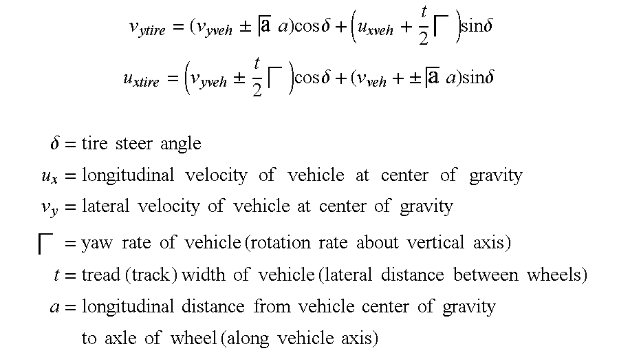
- the tire side slip angle ⁇ may be calculated during operation of the vehicle from various sensors.
- u tire longitudinal velocity of tire along longitudinal axis (heading of tire(.)
- v y and u x are calculated as follows: to generalize, the equation below has + or sign depending if left or right tires is being determined.
- v y ⁇ lateral ⁇ ⁇ velocity ⁇ ⁇ of ⁇ ⁇ vehicle ⁇ ⁇ at ⁇ ⁇ center ⁇
- v x and v y are the longitudinal and lateral velocities of the center of gravity of the vehicle, measured in the body fixed x and y directions.
- the sensors are read in step 60 .
- These sensors may include each of the sensors or some of the sensors shown in FIG. 3 .
- a coefficient of friction for the road surface is determined in step 62 .
- a maximum permissible tire slip angle ⁇ mp1 is calculated in step 64 .
- the maximum permissible tire slip angle may be determined experimentally, analytically, or a combination of the two. In vehicle or adaptive algorithms may also be used.
- a side slip angle ⁇ is determined from the sensors read in step 60 .
- Controller 26 changes the steering road wheel actuator position in direct response to the hand wheel angle.
- the steering actuator is preferably a steer-by-wire system that in addition to hand wheel input provides some input to prevent exceeding a predetermined slip angle to maximize control of the vehicle.
- a steering wheel actuator change ⁇ ⁇ is an angle determined in step 68 based upon the calculated side slip angle and the maximum permissible slip angle calculated in step 64 . That is, if the calculated side slip angle is greater than the maximum permissible side slip angle, the steering wheel actuator position is changed in step 70 by the amount ⁇ ⁇ . Because the process is an iterative process, step 60 is again repeated. That is, because the road conditions are constantly changing new coefficients of friction, maximum permissible side slip angles, and steering angle changes must be constantly updated to allow the maximum permissible side slip angle to approach the peak value ⁇ p . This method is continued until the calculated side slip angle is approximately equal to the maximum permissible side slip angle ⁇ mp or the driver commands a decreased steering angle resulting in the calculated side slip angle being less than the maximum permissible side slip angle ⁇ mp .
- the steering actuator change ⁇ ⁇ is independent of the change in the hand wheel of the automotive vehicle as long as the driver's input would result in ⁇ > ⁇ mp . That is, the change calculated in step 60 - 70 are made in addition to the changes made by the hand wheel. By constantly monitoring the steering angle, the steering actuator change ⁇ ⁇ may be extremely large to compensate for any change in the hand wheel by the vehicle operator. It should also be noted that this process also may be performed with front steering or rear steering or independently controlled steering actuators within an automotive vehicle.
- the process may also monitor the lateral force F lat and determine a steering change thereby.
- the sensors are read in a similar manner to that of step 60 .
- the various sensors may include all or some of the sensors shown in FIG. 3 .
- the lateral force on the wheels and the side slip angle is calculated from the sensors read in step 80 .
- step 84 a steering actuator change angle is calculated to decrease the slip angle of the tire.
- step 86 the lateral force is recalculated to determine if it has increased. If the lateral force has not increased, step 84 is again repeated.
- step 86 if the lateral force has increased, step 88 is executed.
- step 88 the steering actuator change is determined to increase the slip angle.
- step 90 the lateral force is checked to determine if it has decreased. If the lateral force has not decreased, then step 88 is again executed. In step 90 if the lateral force has decreased, the process is repeated in step 80 .
- FIG. 6 provides a peak-seeking method so that the peak ⁇ p corresponding to the maximum lateral force F latmax is achieved.
- this second method is not dependent on tire and vehicle parameter changes, radial loading, camber angle changes, tire pressure and wear, and changes in the slip angle.
- the slip angle will constantly be centered around the peak slip angle ⁇ p . Note this will be continued as long as the driver commanded ⁇ (without control) is greater than ⁇ p .
- the vehicle stability (yaw and vehicle side slip) are continually monitored to maintain stability.
- various types of steering control through various control signals may be performed depending on the vehicle characteristics and the steering system.
- a rack and pinion system may be controlled to provide a desired change in the rear steering angle using a rear control signal temporarily while leaving the front wheels unchanged.
- the direction of the front wheels using a front control signal could also be changed when the rear direction is changed.
- the relative steering angle between the front wheels may be changed by steering control 38 without changing the position or controlling the position of the rear wheel. This may be done by independent control of the front wheels or simultaneous control of the front wheels. Each wheel in an independent system may respond to a respective front right, front left, rear right, or rear left control signal.
- the relative steering angle between the front wheels may be changed in response to detected roll by steering control 38 without changing the position or controlling the position of the front wheels. This may be done by independent control of the rear wheels or simultaneous control of the rear wheels.
Abstract
Description


Claims (20)
Priority Applications (2)
| Application Number | Priority Date | Filing Date | Title |
|---|---|---|---|
| US10/065,424 US6662898B1 (en) | 2002-10-16 | 2002-10-16 | Tire side slip angle control for an automotive vehicle using steering actuators |
| DE10348738A DE10348738B4 (en) | 2002-10-16 | 2003-10-16 | Control system for a motor vehicle and method for controlling a motor vehicle |
Applications Claiming Priority (1)
| Application Number | Priority Date | Filing Date | Title |
|---|---|---|---|
| US10/065,424 US6662898B1 (en) | 2002-10-16 | 2002-10-16 | Tire side slip angle control for an automotive vehicle using steering actuators |
Publications (1)
| Publication Number | Publication Date |
|---|---|
| US6662898B1 true US6662898B1 (en) | 2003-12-16 |
Family
ID=29709259
Family Applications (1)
| Application Number | Title | Priority Date | Filing Date |
|---|---|---|---|
| US10/065,424 Expired - Lifetime US6662898B1 (en) | 2002-10-16 | 2002-10-16 | Tire side slip angle control for an automotive vehicle using steering actuators |
Country Status (2)
| Country | Link |
|---|---|
| US (1) | US6662898B1 (en) |
| DE (1) | DE10348738B4 (en) |
Cited By (25)
| Publication number | Priority date | Publication date | Assignee | Title |
|---|---|---|---|---|
| US20040140147A1 (en) * | 2002-12-11 | 2004-07-22 | Conception Et Developpement Michelin | System for steering a vehicle, having a degraded mode in the event of failure of a wheel steering actuator |
| US20040206570A1 (en) * | 2003-01-23 | 2004-10-21 | Honda Motor Co., Ltd. | Vehicle steering apparatus |
| US6856885B2 (en) * | 2003-04-01 | 2005-02-15 | General Motors Corporation | Vehicle stability enhancement control |
| US6856886B1 (en) * | 2004-03-23 | 2005-02-15 | General Motors Corporation | Vehicle stability enhancement control and method |
| US20050087389A1 (en) * | 2003-10-27 | 2005-04-28 | Marcus Turner | Roll-over controller |
| US20050222731A1 (en) * | 2004-03-30 | 2005-10-06 | Ghoneim Youssef A | Method and apparatus for estimating steering behavior for integrated chassis control |
| US20060006017A1 (en) * | 2004-07-12 | 2006-01-12 | Fuji Jukogyo Kabushiki Kaisha | Wheel ground-contact state judging device and method and vehicle motion control device |
| US7191047B2 (en) | 2004-09-27 | 2007-03-13 | Delphi Technologies, Inc. | Motor vehicle control using a dynamic feedforward approach |
| US20070078581A1 (en) * | 2003-10-24 | 2007-04-05 | Gero Nenninger | Vehicle dynamics control system adapted to the load condition of a vehicle |
| US20070131473A1 (en) * | 2005-12-09 | 2007-06-14 | Ford Global Technologies, Llc | All wheel steering for passenger vehicle |
| US20070173997A1 (en) * | 2006-01-23 | 2007-07-26 | Nissan Motor Co., Ltd. | Sideslip angle estimation apparatus and method and automotive vehicle incorporating the same |
| US7278511B1 (en) * | 2003-01-27 | 2007-10-09 | Polaris Industries Inc. | Controller for steering a vehicle |
| US20080077295A1 (en) * | 2005-02-16 | 2008-03-27 | Knorr-Bremse Systeme Fuer Nutzfahrzeuge Gmbh | Stabilizing system and method for directionally stabilizing a vehicle by reference to a lateral force coefficient |
| US20080109133A1 (en) * | 2006-11-06 | 2008-05-08 | Delphi Technologies, Inc. | Methods, systems, and computer program products for tire slip angle limiting in a steering control system |
| WO2009027801A1 (en) * | 2007-08-31 | 2009-03-05 | Ferrari S.P.A. | Method for controlling the side slip angle of a rear- wheel drive vehicle when turning |
| US20090204292A1 (en) * | 2008-02-11 | 2009-08-13 | Caterpillar Inc. | Traction control system |
| US20090306859A1 (en) * | 2006-04-19 | 2009-12-10 | Marc Andre Tichy | Device and method for triggering passenger protection system in consideration of road grip coefficient |
| US20100114431A1 (en) * | 2008-10-31 | 2010-05-06 | Volkswagen Group Of America, Inc. | Method for Controlling Vehicle Dynamics |
| CN101855117A (en) * | 2007-11-09 | 2010-10-06 | 米其林技术公司 | System for generating an estimation of the ground speed of a vehicle from measures of the rotation speed of at least one wheel |
| US20100256887A1 (en) * | 2007-11-09 | 2010-10-07 | Societe De Technologie Michelin | System for controlling a vehicle with determination of the speed thereof relative to the ground |
| AU2010200598B2 (en) * | 2009-02-12 | 2011-06-30 | Hitachi Construction Machinery Co., Ltd. | Turning motion assistance device for electric vehicle |
| US20120072076A1 (en) * | 2009-05-29 | 2012-03-22 | El-Forest Ab | Hybrid utility vehicle |
| US20120116636A1 (en) * | 2005-10-11 | 2012-05-10 | Renault Trucks | Method for controlling a steer-by-wire steering system |
| US20160123866A1 (en) * | 2013-06-14 | 2016-05-05 | Pirelli Tyre S.P.A. | Method and system for estimating the potential friction between a vehicle tyre and a rolling surface |
| CN115123381A (en) * | 2021-03-26 | 2022-09-30 | 本田技研工业株式会社 | Steering device for vehicle |
Families Citing this family (3)
| Publication number | Priority date | Publication date | Assignee | Title |
|---|---|---|---|---|
| US11498613B2 (en) | 2019-02-14 | 2022-11-15 | Steering Solutions Ip Holding Corporation | Road friction coefficient estimation using steering system signals |
| US11511790B2 (en) | 2019-02-14 | 2022-11-29 | Steering Solutions Ip Holding Corporation | Road friction coefficient estimation using steering system signals |
| DE102020104265B4 (en) | 2019-02-19 | 2024-03-21 | Steering Solutions Ip Holding Corporation | Estimation of a road friction coefficient using signals from a steering system |
Citations (21)
| Publication number | Priority date | Publication date | Assignee | Title |
|---|---|---|---|---|
| US4767588A (en) | 1985-04-13 | 1988-08-30 | Nissan Motor Co., Ltd. | Vehicle control system for controlling side slip angle and yaw rate gain |
| US4951198A (en) | 1987-10-15 | 1990-08-21 | Mazda Motor Corporation | Friction detecting device for vehicles |
| US4967865A (en) | 1988-02-13 | 1990-11-06 | Daimler-Benz Ag | Supplementary steering system |
| US5088040A (en) | 1989-01-18 | 1992-02-11 | Nissan Motor Company, Limited | Automotive control system providing anti-skid steering |
| US5261503A (en) | 1990-07-11 | 1993-11-16 | Aisin Seiki Kabushiki Kaisha | Adaptive steering control system |
| US5278761A (en) | 1992-11-12 | 1994-01-11 | Ford Motor Company | Method for vehicular wheel spin control that adapts to different road traction characteristics |
| US5365439A (en) | 1990-07-06 | 1994-11-15 | Mitsubishi Jidosha Kogyo Kabushiki Kaisha | Method and apparatus for detecting friction coefficient of road surface, and method and system for four-wheel steering of vehicles using the detected friction coefficient of road surface |
| US5579245A (en) | 1993-03-17 | 1996-11-26 | Mitsubishi Jidosha Kogyo Kabushiki Kaisha | Vehicle slip angle measuring method and a device therefor |
| US5627754A (en) * | 1994-03-18 | 1997-05-06 | Honda Giken Kogyo Kabushiki Kaisha | Method for controlling a front and rear wheel steering vehicle |
| US5648903A (en) | 1995-07-10 | 1997-07-15 | Ford Global Technologies, Inc. | Four wheel steering control utilizing front/rear tire longitudinal slip difference |
| US5694319A (en) | 1992-08-13 | 1997-12-02 | Daimler-Benz Ag | Process for the determining travel-situation-dependent steering angle |
| US5729107A (en) * | 1995-08-29 | 1998-03-17 | Honda Giken Kogyo Kabushiki Kaisha | Control device for an electric actuator of a steering system |
| US5765118A (en) * | 1995-03-30 | 1998-06-09 | Toyota Jidosha Kabushiki Kaisha | Estimation method of movement state variable in turning of automotive vehicle |
| US5907277A (en) * | 1996-09-09 | 1999-05-25 | Honda Giken Kogyo Kabushiki Kaisha | Device for detecting a counter-steer condition |
| US5925083A (en) * | 1996-12-07 | 1999-07-20 | Deutsche Forchungsanstalt Fur Luft Und Raumfahrt E.V. | Method of correcting steering of a road driven vehicle |
| US5996724A (en) * | 1996-08-28 | 1999-12-07 | Honda Giken Kabushiki Kaisha | Steering control system |
| US6079513A (en) | 1997-02-12 | 2000-06-27 | Koyo Seiko Co., Ltd | Steering apparatus for vehicle |
| US6184637B1 (en) | 1998-10-26 | 2001-02-06 | Honda Giken Kogyo Kabushiki Kaisha | Electric power steering apparatus |
| US6219604B1 (en) | 1998-12-29 | 2001-04-17 | Robert Bosch Gmbh | Steer-by-wire steering system for motorized vehicles |
| US6263261B1 (en) | 1999-12-21 | 2001-07-17 | Ford Global Technologies, Inc. | Roll over stability control for an automotive vehicle |
| US6405113B1 (en) * | 1999-12-03 | 2002-06-11 | Honda Giken Kogyo Kabushiki Kaisha | Vehicle behavior control apparatus |
Family Cites Families (2)
| Publication number | Priority date | Publication date | Assignee | Title |
|---|---|---|---|---|
| JP3730341B2 (en) * | 1996-11-20 | 2006-01-05 | 本田技研工業株式会社 | Electric power steering device |
| JP3626665B2 (en) * | 2000-06-21 | 2005-03-09 | 光洋精工株式会社 | Vehicle attitude control device |
-
2002
- 2002-10-16 US US10/065,424 patent/US6662898B1/en not_active Expired - Lifetime
-
2003
- 2003-10-16 DE DE10348738A patent/DE10348738B4/en not_active Expired - Fee Related
Patent Citations (21)
| Publication number | Priority date | Publication date | Assignee | Title |
|---|---|---|---|---|
| US4767588A (en) | 1985-04-13 | 1988-08-30 | Nissan Motor Co., Ltd. | Vehicle control system for controlling side slip angle and yaw rate gain |
| US4951198A (en) | 1987-10-15 | 1990-08-21 | Mazda Motor Corporation | Friction detecting device for vehicles |
| US4967865A (en) | 1988-02-13 | 1990-11-06 | Daimler-Benz Ag | Supplementary steering system |
| US5088040A (en) | 1989-01-18 | 1992-02-11 | Nissan Motor Company, Limited | Automotive control system providing anti-skid steering |
| US5365439A (en) | 1990-07-06 | 1994-11-15 | Mitsubishi Jidosha Kogyo Kabushiki Kaisha | Method and apparatus for detecting friction coefficient of road surface, and method and system for four-wheel steering of vehicles using the detected friction coefficient of road surface |
| US5261503A (en) | 1990-07-11 | 1993-11-16 | Aisin Seiki Kabushiki Kaisha | Adaptive steering control system |
| US5694319A (en) | 1992-08-13 | 1997-12-02 | Daimler-Benz Ag | Process for the determining travel-situation-dependent steering angle |
| US5278761A (en) | 1992-11-12 | 1994-01-11 | Ford Motor Company | Method for vehicular wheel spin control that adapts to different road traction characteristics |
| US5579245A (en) | 1993-03-17 | 1996-11-26 | Mitsubishi Jidosha Kogyo Kabushiki Kaisha | Vehicle slip angle measuring method and a device therefor |
| US5627754A (en) * | 1994-03-18 | 1997-05-06 | Honda Giken Kogyo Kabushiki Kaisha | Method for controlling a front and rear wheel steering vehicle |
| US5765118A (en) * | 1995-03-30 | 1998-06-09 | Toyota Jidosha Kabushiki Kaisha | Estimation method of movement state variable in turning of automotive vehicle |
| US5648903A (en) | 1995-07-10 | 1997-07-15 | Ford Global Technologies, Inc. | Four wheel steering control utilizing front/rear tire longitudinal slip difference |
| US5729107A (en) * | 1995-08-29 | 1998-03-17 | Honda Giken Kogyo Kabushiki Kaisha | Control device for an electric actuator of a steering system |
| US5996724A (en) * | 1996-08-28 | 1999-12-07 | Honda Giken Kabushiki Kaisha | Steering control system |
| US5907277A (en) * | 1996-09-09 | 1999-05-25 | Honda Giken Kogyo Kabushiki Kaisha | Device for detecting a counter-steer condition |
| US5925083A (en) * | 1996-12-07 | 1999-07-20 | Deutsche Forchungsanstalt Fur Luft Und Raumfahrt E.V. | Method of correcting steering of a road driven vehicle |
| US6079513A (en) | 1997-02-12 | 2000-06-27 | Koyo Seiko Co., Ltd | Steering apparatus for vehicle |
| US6184637B1 (en) | 1998-10-26 | 2001-02-06 | Honda Giken Kogyo Kabushiki Kaisha | Electric power steering apparatus |
| US6219604B1 (en) | 1998-12-29 | 2001-04-17 | Robert Bosch Gmbh | Steer-by-wire steering system for motorized vehicles |
| US6405113B1 (en) * | 1999-12-03 | 2002-06-11 | Honda Giken Kogyo Kabushiki Kaisha | Vehicle behavior control apparatus |
| US6263261B1 (en) | 1999-12-21 | 2001-07-17 | Ford Global Technologies, Inc. | Roll over stability control for an automotive vehicle |
Non-Patent Citations (1)
| Title |
|---|
| Yasuo Shimizu, Toshitake Kawai, Junji Yuzuriha: Improvement in Driver-Vehicle System Performance by Varying Steering Gain with Vehicle Speed and Steering Angle: VGS (Variable Gear-Ratio Steering System) SAE Technical Paper 1999-01-0395. |
Cited By (40)
| Publication number | Priority date | Publication date | Assignee | Title |
|---|---|---|---|---|
| US6991061B2 (en) * | 2002-12-11 | 2006-01-31 | Conception Et Developpement Michelin S.A. | System for steering a vehicle, having a degraded mode in the event of failure of a wheel steering actuator |
| US20040140147A1 (en) * | 2002-12-11 | 2004-07-22 | Conception Et Developpement Michelin | System for steering a vehicle, having a degraded mode in the event of failure of a wheel steering actuator |
| US20040206570A1 (en) * | 2003-01-23 | 2004-10-21 | Honda Motor Co., Ltd. | Vehicle steering apparatus |
| US7278511B1 (en) * | 2003-01-27 | 2007-10-09 | Polaris Industries Inc. | Controller for steering a vehicle |
| US6856885B2 (en) * | 2003-04-01 | 2005-02-15 | General Motors Corporation | Vehicle stability enhancement control |
| US20070078581A1 (en) * | 2003-10-24 | 2007-04-05 | Gero Nenninger | Vehicle dynamics control system adapted to the load condition of a vehicle |
| US20050087389A1 (en) * | 2003-10-27 | 2005-04-28 | Marcus Turner | Roll-over controller |
| US6968921B2 (en) * | 2003-10-27 | 2005-11-29 | Ford Global Technologies Llc | Roll-over controller |
| US6856886B1 (en) * | 2004-03-23 | 2005-02-15 | General Motors Corporation | Vehicle stability enhancement control and method |
| US7099759B2 (en) * | 2004-03-30 | 2006-08-29 | General Motors Corporation | Method and apparatus for estimating steering behavior for integrated chassis control |
| US20050222731A1 (en) * | 2004-03-30 | 2005-10-06 | Ghoneim Youssef A | Method and apparatus for estimating steering behavior for integrated chassis control |
| US20060006017A1 (en) * | 2004-07-12 | 2006-01-12 | Fuji Jukogyo Kabushiki Kaisha | Wheel ground-contact state judging device and method and vehicle motion control device |
| US7797093B2 (en) * | 2004-07-12 | 2010-09-14 | Fuji Jukogyo Kabushiki Kaisha | Wheel ground-contact state judging device and method |
| US7191047B2 (en) | 2004-09-27 | 2007-03-13 | Delphi Technologies, Inc. | Motor vehicle control using a dynamic feedforward approach |
| US20080077295A1 (en) * | 2005-02-16 | 2008-03-27 | Knorr-Bremse Systeme Fuer Nutzfahrzeuge Gmbh | Stabilizing system and method for directionally stabilizing a vehicle by reference to a lateral force coefficient |
| US20120116636A1 (en) * | 2005-10-11 | 2012-05-10 | Renault Trucks | Method for controlling a steer-by-wire steering system |
| US8301339B2 (en) * | 2005-10-11 | 2012-10-30 | Renault Trucks | Method for controlling a steer-by-wire steering system |
| US20070131473A1 (en) * | 2005-12-09 | 2007-06-14 | Ford Global Technologies, Llc | All wheel steering for passenger vehicle |
| US7844383B2 (en) * | 2006-01-23 | 2010-11-30 | Nissan Motor Co., Ltd. | Sideslip angle estimation apparatus and method and automotive vehicle incorporating the same |
| US20070173997A1 (en) * | 2006-01-23 | 2007-07-26 | Nissan Motor Co., Ltd. | Sideslip angle estimation apparatus and method and automotive vehicle incorporating the same |
| US9150176B2 (en) * | 2006-04-19 | 2015-10-06 | Robert Bosch Gmbh | Device and method for triggering passenger protection system in consideration of road grip coefficient |
| US20090306859A1 (en) * | 2006-04-19 | 2009-12-10 | Marc Andre Tichy | Device and method for triggering passenger protection system in consideration of road grip coefficient |
| US20080109133A1 (en) * | 2006-11-06 | 2008-05-08 | Delphi Technologies, Inc. | Methods, systems, and computer program products for tire slip angle limiting in a steering control system |
| US7756620B2 (en) | 2006-11-06 | 2010-07-13 | Gm Global Technology Operations, Inc. | Methods, systems, and computer program products for tire slip angle limiting in a steering control system |
| WO2009027801A1 (en) * | 2007-08-31 | 2009-03-05 | Ferrari S.P.A. | Method for controlling the side slip angle of a rear- wheel drive vehicle when turning |
| US8527177B2 (en) | 2007-11-09 | 2013-09-03 | Compagnie Generale Des Etablissements Michelin | System for controlling a vehicle with determination of the speed thereof relative to the ground |
| CN101855117A (en) * | 2007-11-09 | 2010-10-06 | 米其林技术公司 | System for generating an estimation of the ground speed of a vehicle from measures of the rotation speed of at least one wheel |
| US20100324766A1 (en) * | 2007-11-09 | 2010-12-23 | Societe De Technologie Michelin | System for generating an estimation of the ground speed of a vehicle from measures of the rotation speed of at least one wheel |
| CN101855117B (en) * | 2007-11-09 | 2013-08-14 | 米其林企业总公司 | System for generating an estimation of the ground speed of a vehicle from measures of the rotation speed of at least one wheel |
| US8370013B2 (en) | 2007-11-09 | 2013-02-05 | Compagnie Generale Des Establissements Michelin | System for generating an estimation of the ground speed of a vehicle from measures of the rotation speed of at least one wheel |
| US20100256887A1 (en) * | 2007-11-09 | 2010-10-07 | Societe De Technologie Michelin | System for controlling a vehicle with determination of the speed thereof relative to the ground |
| US20090204292A1 (en) * | 2008-02-11 | 2009-08-13 | Caterpillar Inc. | Traction control system |
| US7894958B2 (en) * | 2008-02-11 | 2011-02-22 | Caterpillar Inc | Traction control system |
| US20100114431A1 (en) * | 2008-10-31 | 2010-05-06 | Volkswagen Group Of America, Inc. | Method for Controlling Vehicle Dynamics |
| AU2010200598B2 (en) * | 2009-02-12 | 2011-06-30 | Hitachi Construction Machinery Co., Ltd. | Turning motion assistance device for electric vehicle |
| US20120072076A1 (en) * | 2009-05-29 | 2012-03-22 | El-Forest Ab | Hybrid utility vehicle |
| US20160123866A1 (en) * | 2013-06-14 | 2016-05-05 | Pirelli Tyre S.P.A. | Method and system for estimating the potential friction between a vehicle tyre and a rolling surface |
| US9746414B2 (en) * | 2013-06-14 | 2017-08-29 | Pirelli Tyre S.P.A. | Method and system for estimating the potential friction between a vehicle tyre and a rolling surface |
| CN115123381A (en) * | 2021-03-26 | 2022-09-30 | 本田技研工业株式会社 | Steering device for vehicle |
| CN115123381B (en) * | 2021-03-26 | 2024-02-23 | 本田技研工业株式会社 | Steering device for vehicle |
Also Published As
| Publication number | Publication date |
|---|---|
| DE10348738A1 (en) | 2004-05-06 |
| DE10348738B4 (en) | 2010-08-26 |
Similar Documents
| Publication | Publication Date | Title |
|---|---|---|
| US6662898B1 (en) | Tire side slip angle control for an automotive vehicle using steering actuators | |
| EP1234741B2 (en) | Rollover stability control for an automotive vehicle | |
| US7143864B2 (en) | Yaw control for an automotive vehicle using steering actuators | |
| US7647148B2 (en) | Roll stability control system for an automotive vehicle using coordinated control of anti-roll bar and brakes | |
| US6654674B2 (en) | Enhanced system for yaw stability control system to include roll stability control function | |
| US6496758B2 (en) | Rollover stability control for an automotive vehicle using front wheel actuators | |
| US7140619B2 (en) | Roll over stability control for an automotive vehicle having an active suspension | |
| US7600826B2 (en) | System for dynamically determining axle loadings of a moving vehicle using integrated sensing system and its application in vehicle dynamics controls | |
| US6529803B2 (en) | Roll over stability control for an automotive vehicle having rear wheel steering | |
| US7130735B2 (en) | Roll over stability control for an automotive vehicle | |
| US8775048B2 (en) | Method and apparatus for determining a reference vehicle velocity and a rear wheel speed in a vehicle having three speed sensors | |
| US6334656B1 (en) | Method and system for controlling the yaw moment of a vehicle | |
| US6840343B2 (en) | Tire side slip angle control for an automotive vehicle using steering peak seeking actuators | |
| US8121758B2 (en) | System for determining torque and tire forces using integrated sensing system | |
| JP4821490B2 (en) | Driving control device and driving control method during straight braking of vehicle | |
| US7308350B2 (en) | Method and apparatus for determining adaptive brake gain parameters for use in a safety system of an automotive vehicle | |
| US11912351B2 (en) | Steering control device and steering device | |
| US7433768B2 (en) | Method for determining a steering-wheel torque |
Legal Events
| Date | Code | Title | Description |
|---|---|---|---|
| AS | Assignment |
Owner name: FORD GLOBAL TECHNOLOGIES, INC., MICHIGAN Free format text: ASSIGNMENT OF ASSIGNORS INTEREST;ASSIGNOR:FORD MOTOR COMPANY;REEL/FRAME:013183/0813 Effective date: 20021009 Owner name: FORD MOTOR COMPANY, MICHIGAN Free format text: ASSIGNMENT OF ASSIGNORS INTEREST;ASSIGNORS:MATTSON, KEITH GLENN;BROWN, TODD ALLEN;REEL/FRAME:013183/0794 Effective date: 20021005 |
|
| AS | Assignment |
Owner name: FORD GLOBAL TECHNOLOGIES, LLC, MICHIGAN Free format text: MERGER;ASSIGNOR:FORD GLOBAL TECHNOLOGIES, INC.;REEL/FRAME:013987/0838 Effective date: 20030301 Owner name: FORD GLOBAL TECHNOLOGIES, LLC,MICHIGAN Free format text: MERGER;ASSIGNOR:FORD GLOBAL TECHNOLOGIES, INC.;REEL/FRAME:013987/0838 Effective date: 20030301 |
|
| STCF | Information on status: patent grant |
Free format text: PATENTED CASE |
|
| FPAY | Fee payment |
Year of fee payment: 4 |
|
| FPAY | Fee payment |
Year of fee payment: 8 |
|
| FPAY | Fee payment |
Year of fee payment: 12 |