US6669001B1 - Linear belt sorter and methods of using linear belt sorter - Google Patents
Linear belt sorter and methods of using linear belt sorter Download PDFInfo
- Publication number
- US6669001B1 US6669001B1 US10/292,224 US29222402A US6669001B1 US 6669001 B1 US6669001 B1 US 6669001B1 US 29222402 A US29222402 A US 29222402A US 6669001 B1 US6669001 B1 US 6669001B1
- Authority
- US
- United States
- Prior art keywords
- carriers
- slat
- carrier
- endless loop
- belt
- Prior art date
- Legal status (The legal status is an assumption and is not a legal conclusion. Google has not performed a legal analysis and makes no representation as to the accuracy of the status listed.)
- Expired - Lifetime
Links
Images


Classifications
-
- B—PERFORMING OPERATIONS; TRANSPORTING
- B65—CONVEYING; PACKING; STORING; HANDLING THIN OR FILAMENTARY MATERIAL
- B65G—TRANSPORT OR STORAGE DEVICES, e.g. CONVEYORS FOR LOADING OR TIPPING, SHOP CONVEYOR SYSTEMS OR PNEUMATIC TUBE CONVEYORS
- B65G17/00—Conveyors having an endless traction element, e.g. a chain, transmitting movement to a continuous or substantially-continuous load-carrying surface or to a series of individual load-carriers; Endless-chain conveyors in which the chains form the load-carrying surface
- B65G17/30—Details; Auxiliary devices
- B65G17/32—Individual load-carriers
- B65G17/34—Individual load-carriers having flat surfaces, e.g. platforms, grids, forks
- B65G17/345—Individual load-carriers having flat surfaces, e.g. platforms, grids, forks the surfaces being equipped with a conveyor
-
- B—PERFORMING OPERATIONS; TRANSPORTING
- B65—CONVEYING; PACKING; STORING; HANDLING THIN OR FILAMENTARY MATERIAL
- B65G—TRANSPORT OR STORAGE DEVICES, e.g. CONVEYORS FOR LOADING OR TIPPING, SHOP CONVEYOR SYSTEMS OR PNEUMATIC TUBE CONVEYORS
- B65G2207/00—Indexing codes relating to constructional details, configuration and additional features of a handling device, e.g. Conveyors
- B65G2207/18—Crossing conveyors
Definitions
- the present invention relates to endless loop sorters which have carriers that utilize belts to both transport and sort numerous items. Sortation of items of different sizes and shapes is within the scope of the present invention. And when the items to be sorted mandate, gripping enhancers can be applied to carriers' belts.
- followers clasp the belts about the lengthwise periphery of the carriers' slats.
- the followers also move about the lengths of their respective slats.
- Select embodiments equip the carriers with guide bearings for the followers.
- riders depend downward from the followers' clasps and through slits in the guide bearings to engage lines, diverters, crossovers or receivers. When a diverter diverts a follower from a line toward a crossover transverse motion is imparted to the carrier's belt.
- the diverters can divert sequential followers, in series.
- the followers can also include delays for prolonging the longevity of the diverters.
- Other embodiments include spatial orientations for the endless loop's carriers that virtually eliminate hiatuses between the sequential carriers. Still other embodiments of the current invention eliminate the gaps between the carriers.
- U.S. Pat. No. 4,930,613-Okura, et. al. enables a carrier including a flat belt ( 6 ).
- the flat belt ( 6 ) is capable of transferring items to be sorted at angles transverse to the forward movement of Okura's carrier.
- Two end portions of the belt ( 6 ) are fitted alternately in a folded back manner on the two side rollers ( 4 ) and inner rollers ( 5 ) and thereafter fixed to two sides of the carrier.
- Okura's carrier further includes his moving frame ( 3 ) that includes a depending roller ( 7 ) and depending pin ( 8 ).
- Pen ( 8 ) and roller ( 7 ) engage actuators ( 9 a - 9 d ) disposed in the transferring passage ( 2 ).
- the '613 moving frame ( 3 ) is formed by folding two ends of a narrow plate upward and equipping the frame ( 3 ) with a plurality of horizontal ( 19 ) and vertical ( 20 ) wheels. These wheels engage a pair of guide rails ( 21 ), and in operation, the Okura frame ( 3 ) moves at a right angle with respect the directional movement of the carrier ( 1 ).
- inner rollers ( 5 ) must be arranged inside moving frame ( 3 ).
- U.S. Pat. No. 4,884,676-Suizu teaches a type of cross-belt sorter. Suizu's belt ( 11 ) circumscribes his moving frame ( 4 ) while rollers ( 5 ) engage rails ( 2 ) and support the moving frame ( 4 ). The '676 drive pulley ( 13 ) causes belt ( 11 ) to move at right angles as compared with the forward motion of the moving frame ( 4 ).
- Suizu's combination of friction wheels ( 16 , 17 ), drive pulley ( 13 ), shafts ( 16 a , 17 a ), bevel gear ( 24 ), shaft ( 24 a ), bearings ( 25 ), shaft ( 13 a ), sprockets ( 26 , 27 ) and endless chain ( 28 ) form the transmission for moving frame ( 4 ).
- the belt ( 11 ) is able to move transversely due to Suizu's elaborate transmission.
- U.S. Pat. No. 4,096,936-Nielson discloses a cross belt sorting conveyor.
- Nielson's belt ( 2 ) is supported by a plurality of wheels ( 26 ) mounted in brackets ( 28 ) which in turn are carried on vertical shaft pins ( 30 ) rotably secured to the base plate ( 32 ).
- the '936 belt elements ( 4 ) rest on the top of wheels ( 26 ) directly with the lower side of the individual cross conveyor belts ( 12 ).
- U.S. Pat. No. 6,273,268-Axmann enables a conveyor system for sorting piece goods.
- Axmann's combination of electro-magnetically or pneumatically actuated friction strips ( 36 ), friction wheel ( 32 ), shaft ( 31 ), bevel gear ( 30 ) and friction rollers ( 26 ) drive the sorting device's conveyor belt ( 18 ) to revolve toward an ejection station. Since the '268 Patent's friction wheel can be actuated in either direction, the Axmann belt can eject piece goods to either side of the conveyor.
- U.S. Pat. No. 5,901,830-Kalm, et. al. discloses an electrically actuated bi-directional belt sorter.
- the '830 carrier ( 10 ) includes a pair of rollers ( 31 , 32 ) supported at opposite ends of the top ( 12 ) of the carrier ( 10 ).
- Kalm's drive motor ( 38 ) is powered by the electrified track ( 200 ).
- the conveyor belt ( 36 ) is actuated by the rollers ( 31 , 32 ), and in the preferred embodiment, drive belt ( 52 ) connects a pair of drive pulleys ( 54 , 56 ).
- Kalm's drive pulley ( 54 ) is connected to roller ( 32 ) while drive pulley ( 56 ) is connected to the output shaft ( 40 ) of drive motor ( 38 ).
- U.S. Pat. No. 4,781,281-Canziani defines a conveyor and discharge system for sorting items.
- Canziani mounts belt ( 3 ) to his carriage ( 1 ).
- the shaft ( 6 ) of roll ( 4 ) is keyed to pinion ( 7 ) for engaging corresponding pinion ( 8 ) of shaft ( 9 ).
- wheel ( 12 ) of shaft ( 9 ) is seized between belts ( 13 , 14 )
- rotary motion is transmitted to roll ( 4 ) causing the belt ( 3 ) to rotate to discharge any item thereon.
- U.S. Pat. No. 4,815,582-Canziani describes a cross-belt sorting apparatus incorporating permanent magnet D.C. electric motors to rotate the rotary belts ( 5 , 14 ).
- U.S. Pat. No. 5,690,209-Kofoed enables a cross-belt sorter.
- the '209 Patent utilizes electric motors for driving each carrier's belt transverse to the movement of the Kofoed endless loop which is consists of a plurality of chassis linked together to form a continuous chain.
- U.S. Pat. No. 4,763,771-Geerts discloses a sorter utilizing trolleys.
- the Geerts trolley consists of an endless belt ( 7 ) running over pulleys ( 6 ).
- the pulleys ( 6 ) are fixed on axle ( 24 ).
- a first cable ( 25 ) and a second cable ( 27 ) are each wound around the axle ( 24 ). The combination of the cables, the axle and the pulleys drive the belt ( 7 ) to throw its load off.
- the present apparatus can diverter two or more of the endless loop's followers, in series, resulting in the sortation of the larger sized item. Conversely, when the size of the item to be sorted is smaller than or about the width of a single belt, a single follower is diverted which precipitates sortation of the smaller item.
- carrier belts may be of differing widths or they can be equipped with a gripping enhancer.
- a controller activates the diverters to divert the sorter's followers.
- a follower When a follower is diverted, transverse motion is imparted to the carrier's belt.
- electromagnetic induction can be used to guide the followers, but more often, mechanical tracks, electromechanical diverters, mechanical crossovers and mechanical receivers direct the sorter's followers as the endless loop is advanced.
- an endless loop having an upper half and a lower half, is formed.
- the sorter's followers are guided about the length of the carriers' slats by the carriers' guide bearings, but the carriers can be sized so that the followers do not travel the entire lengths of the slats.
- guide bearings can include slits for the followers' riders.
- the riders may also incorporate depending bearings for engaging the sorter's lines, diverters or crossovers. Such embodiments have been found to meet the long felt need of reducing the wear and tear of the sorter's diverters.
- the hiatuses between the endless loop's carriers are virtually eliminated. And as will be enabled more fully hereinafter, in other embodiments, gaps between the carriers are eliminated. The gaps may be eliminated by protruding the carriers' belts over the lengthwise edges of the carriers slats. Importantly and regardless of the embodiment practiced, the carriers are dimensioned to pivot through a reverse bend or reverse pivot, when required, as the endless loop circulates or advances about the sorter.
- An object of the present invention is to provide a sorter utilizing carrier belts for sorting items.
- Still another object of the present invention is to provide clasping followers for the sorter's carriers.
- Yet another object of the present invention is to incorporate a delay into the carrier's follower so that the impartation of transverse motion to the carrier's belt is delayed for a predetermined time or distance.
- Still another object of the present invention is to provide a follower including at least a one centimeter leeway.
- Yet still another object of the present invention is to reduce wear and tear on the diverters.
- Still another object of the present invention is to eliminate the gaps between the endless loop's carriers.
- Yet another object of the present invention is to dimension the endless loop's carriers to pivot through a reverse bend or reverse pivot.
- Still another object of the present invention is to divert a single follower, thereby activating a single carrier's belt to sort a single item.
- Yet another object of the present invention is to divert sequential followers, in series, thereby activating a series of carriers' belts to sort a single item.
- An embodiment of the present invention can be described as a sorter for sorting a plurality of items, comprising: an endless loop, wherein the endless loop further comprises a plurality of carriers circulating about the endless loop and wherein one or more of the carriers further comprises: a slat; a belt having a length approximate a lengthwise periphery of the slat, a follower for clasping the belt about the slat, and at least one connector; a plurality of lines for directing advancement of any of the followers; a plurality of crossovers for guiding transversely, relative to said endless loop's advancement, any of the followers; a diverter; a drive; a frame and a controller.
- a carrier for carrying a plurality of items for sorting comprising: a slat; a belt fitted for and wrapped about a lengthwise periphery of the slat; a follower, including a rider for clasping the belt about the slat; a guide bearing for the follower; and at least one connector.
- Still another embodiment of the present invention can be described as a method of imparting transverse motion to a belt of a carrier of an endless loop, comprising the steps of: creating a carrier, further comprising the steps of: wrapping the belt about a slat, clasping the belt about the slat with a clasp, depending a rider from the clasp for generating a follower, forming a guide bearing beneath the slat, including a slit in the guide bearing for the follower and incorporating a delay into the follower; connecting the carriers to a drive for creating the endless loop; circulating or advancing the endless loop; diverting one or more of the followers toward at least one crossover; and controlling advancement of and the diversion the followers.
- Yet another embodiment of the present device can be described as a sorter for sorting a plurality of items, comprising: an endless loop having an upper half positioned above a lower half further comprising a plurality of circulating carriers, wherein one or more of the carriers further comprise: a slat; a belt having a length approximate a lengthwise periphery of the slat; a follower, including a rider, for clasping the belt about the slat and for moving the belt about the lengthwise periphery of the slat; at least one connector; a guide bearing for the follower; a plurality of lines; a plurality of crossovers; a plurality of diverters; a drive; a frame and a controller.
- FIG. 1 depicts a side view perspective the endless loop, within the scope of the present invention.
- FIG. 2 is another representation of a sectional top view of sorter.
- FIG. 3 is a sectional bottom view of an embodiment of the present invention that portrays a mechanical delay of the follower.
- FIG. 4 is a lateral view of a follower's clasp of the present invention.
- FIG. 5 is another view of a second type of follower, within the scope of the present invention.
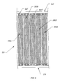
- FIG. 6 is a frontal perspective of the sorter showing the upper half of the endless loop.
- FIG. 7 is a side view of a section of the endless loop, with the frame, cross-members, drive and connectors cut away.
- FIG. 8 is lateral view of a portion of FIG. 7 's carriers disclosing the reverse pivot configuration.
- FIG. 9 is a top plan view of a section of the endless loop.
- FIG. 10 is a sectional side view of another embodiment of the present invention.
- FIG. 11 is lateral view of a portion of FIG. 10 's carriers disclosing the reverse pivot configuration.
- FIGS. 12 is a schematic representations of lines, diverters and crossovers of an embodiment of the present invention.
- FIG. 13 is a top perspective of a diverter, within the scope of the present invention.
- FIG. 14 is an illustration of the steps of an embodiment of the present method.
- FIG. 15 is a depiction of the steps of another embodiment of the present invention.
- FIG. 16 is an exemplification of the steps of yet another embodiment of the current method.
- FIG. 17 is a depiction of the steps of still another embodiment of the present invention.
- FIG. 18 is an illustration of the steps of yet another embodiment of the present method.
- FIG. 19 is an exemplification of the steps of yet another embodiment of the current method.
- FIG. 1 depicts a side view perspective the endless loop of a sorter within the scope of the present invention.
- the plurality of interconnected carriers ( 30 A, 30 B, 30 C, 30 D, 30 E, etcetera) create endless loop ( 90 ), and as portrayed, endless loop ( 90 ) circulates with its upper half ( 92 ) positioned above its lower half ( 94 ).
- a drive (not shown) advances or circulates the endless loop ( 90 ).
- Frame ( 22 ) can be manufactured from any material suitable in the art. And as will be later enabled and disclosed, frame ( 22 ) supports the sorter's drive, lines, crossovers and receivers, as well as the required circuitry for controlling diversion of the followers.
- a controller (not shown), such as a computer program, correlates advancement of the sorter and the diversion of the followers.
- FIG. 2 is a sectional top view of sorter ( 20 ) having its carriers, lines, crossovers, diverters, receivers and switches cutaway.
- Frame ( 22 ) includes a pair of side rails ( 24 and 24 ′). Extending between side rails ( 24 and 24 ′) are cross members ( 26 A, 26 B, 26 C, 26 D and 26 E). Positioned near side rail ( 24 ) and above cross-members ( 26 A, 26 B, 26 C, 26 D and 26 E) is drive member ( 68 ). Located near side rail ( 24 ′) and above cross members ( 26 A, 26 B, 26 C, 26 D and 26 E) is drive member ( 68 ′). As illustrated, each drive member ( 68 , 68 ′) is a chain. However, within the scope of the present invention, other types of drives can be utilized to advance endless loop ( 90 ).
- FIG. 3 is a sectional bottom view of an embodiment of the present invention depicting a mechanical delay ( 60 ) for follower ( 40 ).
- Clasp ( 42 ) of follower ( 40 ) tracks in guide bearing ( 80 ) of carrier ( 30 ).
- rider ( 78 ) can be provided with grooves (not shown) for rider ( 78 ).
- Coupling rider ( 78 ) with the grooves of clasp ( 42 ) allows rider to travel about the length of slot ( 62 ). End ( 63 ) and ( 64 ) of slot ( 60 ) function as a catch.
- clasp ( 42 ) of follower ( 40 ) rides within guide bearing ( 80 ) of carrier ( 30 ), and rider ( 78 ) depends downward through slit ( 82 ) of guide bearing ( 80 ).
- Clasp ( 42 ) of follower ( 40 ) includes upper section ( 44 ) and lower section ( 46 ).
- the upper section ( 44 ) of clasp ( 42 ) is proximate the lower planar side of the slat (not shown) while rider ( 78 ) depends downward from slot ( 60 ) of follower ( 40 ).
- bolts ( 48 ) and ( 50 ) secure upper section ( 44 ) of clasp ( 42 ) to lower section ( 46 ) of clasp ( 42 ).
- other means can be utilized to secure upper section ( 44 ) of clasp ( 42 ) to lower section ( 46 ) of clasp ( 42 ).
- FIG. 5 Another embodiment of the present invention's follower is disclosed in FIG. 5 .
- follower ( 40 ) includes rider ( 78 ) depending downward from lower section ( 46 ) of clasp ( 42 ). Rider ( 78 ) is further provided with depending bearing ( 54 ). And although not shown in this view, follower can also include delay ( 60 ). As best indicated by the FIG. 12 cutaway, in operation, rider ( 78 ) and depending bearing ( 54 ) are directed by either lines, crossovers, diverters, receivers and/or switches.
- follower ( 40 ) can be driven by electromagnetic induction.
- a magnet (not shown) can be attached or incorporated into lower section ( 46 ) of clasp ( 42 ). Thus, follower ( 40 ) can respond to the electromagnetic activation.
- FIG. 6 is a frontal perspective of sorter ( 20 ) showing the upper half ( 92 ) of endless loop ( 90 ). Only the structural elements associated with a single carrier ( 30 ) of the plurality of carriers ( 30 A, B, C, D, E, etcetera) of endless loop ( 90 ) are portrayed in the view. Other carriers of the plurality of carriers ( 30 A, B, C, D, E, etcetera) of endless loop ( 90 ) can have comparable, if not identical, structures. And although not shown, as endless loop ( 90 ) circulates lower half ( 94 ) is controlled and guided in any manner acceptable in the art, including such configurations, as catenary take-ups.
- frame ( 22 ) supports line ( 100 ) and carrier ( 30 ).
- Cross-member ( 26 A) secures side rail ( 24 ′) to side rail ( 24 ).
- Bolt ( 98 ) attaches line ( 100 ) to cross-member ( 26 A) and bolt ( 96 ) affixes line ( 102 ) to cross-member ( 26 A).
- Drive ( 68 ′) rides along platform ( 66 ′) that extends inward from side rail ( 24 ′) of frame ( 22 ), and drive ( 68 ) rides along platform ( 66 ) that extends inward from side rail ( 24 ) of frame ( 22 ).
- braces ( 28 ) and ( 28 ′) extend respectively between cross-member ( 26 A) and platforms ( 66 ) and ( 66 ′).
- couplers ( 72 A and 72 B) of connector ( 70 ′) connect carrier ( 30 ) to drive ( 68 ′).
- Cover ( 74 ′) extends over drive ( 68 ′) and inward from side rail ( 24 ′).
- couplers ( 72 C and 72 D) of connector ( 70 ) connect carrier ( 30 ) to drive ( 68 ).
- Cover ( 74 ) extends over drive ( 68 ) and inward from side rail ( 24 ).
- Connectors ( 70 ′ and 70 ) can be made in a generally U-shape to bend respectively about ends ( 35 ) and ( 37 ) of slat ( 32 ) of carrier ( 30 ).
- carrier ( 30 ) includes slat ( 32 ), roller ( 34 ), roller ( 36 ), belt ( 38 ) and follower ( 40 ).
- Roller ( 34 ) is disposed at the opposite end of slat ( 32 ) from roller ( 36 ).
- Connector ( 70 ′) can support slat ( 32 ) and also include bracket (not shown) to support roller ( 34 ).
- connector ( 70 ) can support slat ( 32 ) and also include bracket (not shown) to support roller ( 36 ).
- slat ( 32 ) can be manufactured to incorporate first outwardly curved edge and second outwardly curved edge (not shown), thereby eliminating the rollers ( 34 , 36 ).
- slat ( 32 ) can be equipped with apertures (not shown) to receive bolts ( 202 F), ( 204 F), ( 206 F) and ( 208 F) for coupling connectors ( 70 ′ and 70 ) to slat ( 32 ).
- the reward side of slat ( 32 ) can also be equipped with apertures for receiving bolts ( 202 R), ( 204 R), ( 206 R) and ( 208 R).
- the slat, bolt, aperture combination allows for adjustment of the tension on belt ( 38 ) of carrier ( 30 ).
- the tension on belt ( 38 ) is modified.
- rider ( 78 ) of follower ( 40 ) depends downward and engages line ( 100 ).
- follower ( 40 ) will travel along line ( 100 ) until diverted onto a crossover (not shown).
- follower ( 40 ) imparts transverse motion to belt ( 38 ), until follower ( 40 ) engages line ( 102 ).
- follower ( 40 ) moves belt ( 38 ) about the lengthwise periphery of slat ( 32 ).
- the lengthwise periphery of slat ( 32 ) is parallel to the cross-member ( 26 A).
- FIG. 7 is a side view of a section of endless loop ( 90 ) of sorter ( 20 ), with frame ( 22 ), cross-members ( 26 ), drive ( 68 ) and couplers ( 72 A, 72 B, etcetera) of connectors ( 70 ) cut away.
- Belts ( 38 A), ( 38 B), ( 38 C) and ( 38 D) are fitted and wrapped about the lengthwise periphery of their corresponding slats (not shown) of carriers ( 30 A), ( 30 B), ( 30 C) and ( 30 D).
- riders ( 78 A, B, C and D) including depending bearings ( 54 A, B, C and D).
- Riders ( 78 A, B, C and D) can travel the length of their corresponding slits ( 82 A, B, C and D) of guide bearings ( 80 A, B, C and D).
- carriers ( 30 A), ( 30 B), ( 30 C) and ( 30 D) are configured to show their forward pivoting ability, while in FIG. 8, carriers ( 30 A), ( 30 B) and ( 30 C) are shown in a reverse pivot configuration, such as carriers ( 30 A), ( 30 B) and ( 30 C) may encounter when traversing the previously enabled lower half of the endless loop.
- the vertical lines of zone X represent the narrowest hiatus separating ( 30 A) from carrier ( 30 B).
- the vertical lines of zone Y represent the narrowest hiatus between carrier ( 30 B) and carrier ( 30 C) while the lines of zone Z represent the hiatus separating carrier ( 30 C) from carrier ( 30 D). It has been determined that the distance for each of the zones X, Y or Z, etcetera, can be dimensioned to be twenty millimeters or less.
- FIG. 9 is a top plan view of a section of endless loop ( 90 ). From this perspective, it seen that the distances between belts ( 38 A) and ( 38 B), belts ( 38 B) and ( 38 C), belts ( 38 C) and ( 38 D), and belts ( 38 D) and ( 38 E) are virtually eliminated. In fact, the hiatuses of each zones X, Y, Z, so forth and so on, are limited only by the structural parameters necessary for any of the plurality of carriers ( 30 A, B, C, D, E, etcetera) to freely reverse pivot, as endless loop ( 90 ) is circulated.
- FIG. 10 a sectional side view of another embodiment of the present invention is disclosed.
- Belts ( 38 A), ( 38 B), ( 38 C) and ( 38 D) are wrapped about the lengthwise periphery of their corresponding slats ( 32 A), ( 32 B), ( 32 C) and ( 32 D) of their respective carriers ( 30 A), ( 30 B), ( 30 C) and ( 30 D).
- gap ( 76 A) is between carriers ( 30 A) and ( 30 B);
- gap ( 76 B) is between carriers ( 30 B) and ( 30 C); and
- gap ( 76 C) is between carriers ( 30 C) and ( 30 D).
- Portion ( 39 B) of belt ( 38 B) protrudes over the lengthwise edge ( 37 B) of slat ( 32 B) to contact slat ( 32 A) thereby preventing items to be sorted from falling into gap ( 76 A).
- portion ( 39 C) of belt ( 38 C) protrudes over the lengthwise edge ( 37 C) of slat ( 32 C) to contact slat ( 32 B) to prevent items from falling into gap ( 76 B)
- portion ( 39 D) of belt ( 38 D) protrudes over the lengthwise edge ( 37 D) of slat ( 32 D) to contact slat ( 32 C) to prevent items from falling into gap ( 76 C).
- riders ( 78 A, B, C and D) including depending bearings ( 54 A, B, C and D). Clasps ( 42 A, B, C and D) of followers ( 40 A, B, C and D) ride in guide bearings ( 80 A, B, C and D). And riders ( 78 A, B, C and D) can travel the approximate length of their corresponding slits ( 82 A, B, C and D) of guide bearings ( 80 A, B, C and D). As shown in FIG.
- carriers ( 30 A), ( 30 B), ( 30 C) and ( 30 D) are configured to show their forward pivoting ability which will occur when carriers ( 30 A), ( 30 B), ( 30 C) and ( 30 D) are advancing in the upper half ( 92 ) of endless loop ( 90 ).
- carriers ( 30 A), ( 30 B) and ( 30 C) are shown in a reverse pivoting configuration that occurs, if necessary, when carriers ( 30 A), ( 30 B) and ( 30 C) are advancing in the lower half ( 94 ) of endless loop ( 90 ).
- FIG. 12 is a representation of lines, diverters, crossovers, receivers and switches that can be used to guide the followers ( 40 A, B, C, D, etcetera) of sorter's carriers ( 30 A, B, C, D, etcetera) of endless loop ( 90 ).
- Line ( 100 ) includes diverter ( 110 ).
- Line ( 102 ) intersects diverter ( 120 ) and diverter ( 122 ).
- Crossover ( 140 ) runs from diverter ( 120 ) to receiver ( 130 ) of line ( 100 ), and crossover ( 142 ) runs from diverter ( 122 ) to receiver ( 132 ) of line ( 100 ).
- Crossover ( 150 ) runs from diverter ( 110 ) of line ( 100 ) to receiver ( 134 ) of line ( 102 ).
- Select embodiments can also incorporate switch ( 170 ) at the junction of crossover ( 142 ) and crossover ( 150 ). And depending upon predetermined sorting parameters, additional diverters, receivers and switches are within the scope of the present invention.
- a controller such as, a computer program, and its corresponding circuitry (not shown) control diversion of the endless loop's carriers' followers.
- the sorter's diverters divert one or more of the followers ( 40 A, B, C, D, etcetera).
- a follower ( 40 ) is guided through a crossover, its corresponding carrier's belt ( 38 ) moves about the lengthwise periphery of the slat ( 32 ) causing an item carried by the belt ( 38 ) to be sorted.
- FIG. 13 is a top perspective of a type of diverter ( 110 ) that can be utilized to practice the present sorter.
- Diverter ( 110 ) is attached to cross-member ( 26 ) through any manner acceptable in the art.
- the diverter ( 110 ) is linked to the controller via the necessary circuitry.
- Diverter ( 110 ) is constructed of metal or plastic and is designed to include channel continuance ( 180 ) fitted and aligned with line ( 100 ).
- Upon activation gate ( 126 ) closes channel continuance ( 180 ) and diverts follower (not shown) into divert groove ( 182 ) leading to crossover ( 150 ).
- carriers ( 30 A, B, C, D, etcetera) incorporating followers ( 40 A, B, C, D, etcetera) having depending bearings ( 54 A, B, C, D, etcetera) and including the previously identified delays ( 60 A, B, C, D, etcetera) reduce the wear and tear of diverter ( 110 ).
- predetermined parameters determine the numerous configurations for the layouts of the sorter's lines, crossovers, diverters and receivers.
- the current sorter can be utilized to sort a plethora of items of differing sizes.
- a diverter can divert a single follower ( 40 ) from a line to a crossover.
- the protruding belts ( 38 A, B, C, D, etcetera) of carriers ( 30 A, B, C, D, etcetera) prevent the smaller items and/or smaller parts of the larger items from falling into gaps ( 76 A, B, C, D, etcetera).
- the controller can activate the diverter to diverter a series of sequential followers ( 40 A, B, C, D, etcetera) from a line to a crossover, thereby sorting the larger item.
- FIGS. 14-19 Steps associated with the practice of the methods of present invention utilizing select structural elements enabled above are set forth in FIGS. 14-19. Having disclosed the invention as required by Title 35 of the United States Code, Applicants now strig respectfully that Letters Patent be granted for their invention in accordance with the scope of the claims appended hereto.
Abstract
Description
Claims (26)
Priority Applications (3)
| Application Number | Priority Date | Filing Date | Title |
|---|---|---|---|
| US10/292,224 US6669001B1 (en) | 2002-11-12 | 2002-11-12 | Linear belt sorter and methods of using linear belt sorter |
| CA002448133A CA2448133C (en) | 2002-11-12 | 2003-11-04 | Linear belt sorter and methods of using linear belt sorter |
| US10/702,779 US6854584B2 (en) | 2002-11-12 | 2003-11-06 | Linear belt sorter and methods of using linear belt sorter |
Applications Claiming Priority (1)
| Application Number | Priority Date | Filing Date | Title |
|---|---|---|---|
| US10/292,224 US6669001B1 (en) | 2002-11-12 | 2002-11-12 | Linear belt sorter and methods of using linear belt sorter |
Related Child Applications (1)
| Application Number | Title | Priority Date | Filing Date |
|---|---|---|---|
| US10/702,779 Continuation-In-Part US6854584B2 (en) | 2002-11-12 | 2003-11-06 | Linear belt sorter and methods of using linear belt sorter |
Publications (1)
| Publication Number | Publication Date |
|---|---|
| US6669001B1 true US6669001B1 (en) | 2003-12-30 |
Family
ID=29735782
Family Applications (2)
| Application Number | Title | Priority Date | Filing Date |
|---|---|---|---|
| US10/292,224 Expired - Lifetime US6669001B1 (en) | 2002-11-12 | 2002-11-12 | Linear belt sorter and methods of using linear belt sorter |
| US10/702,779 Expired - Lifetime US6854584B2 (en) | 2002-11-12 | 2003-11-06 | Linear belt sorter and methods of using linear belt sorter |
Family Applications After (1)
| Application Number | Title | Priority Date | Filing Date |
|---|---|---|---|
| US10/702,779 Expired - Lifetime US6854584B2 (en) | 2002-11-12 | 2003-11-06 | Linear belt sorter and methods of using linear belt sorter |
Country Status (2)
| Country | Link |
|---|---|
| US (2) | US6669001B1 (en) |
| CA (1) | CA2448133C (en) |
Cited By (14)
| Publication number | Priority date | Publication date | Assignee | Title |
|---|---|---|---|---|
| US20030221935A1 (en) * | 1998-12-01 | 2003-12-04 | Crisplant A/S | Conveyor/sorter system, a loading conveyor and a control system for such conveyors |
| US20040089514A1 (en) * | 2002-11-12 | 2004-05-13 | Henson Mark W. | Linear belt sorter and methods of using linear belt sorter |
| US20060021540A1 (en) * | 2002-10-16 | 2006-02-02 | Robert Austin | Monorail sortation system |
| US20070209905A1 (en) * | 2006-03-13 | 2007-09-13 | Tarlton Curtis S | Combining conveyor with product path switching arrangement |
| US20070295579A1 (en) * | 2006-05-12 | 2007-12-27 | Fki Logistex Inc. | Sortation Conveyor Apparatus and Methods |
| EP1897824A1 (en) * | 2006-09-08 | 2008-03-12 | Siemens Aktiengesellschaft | Piece goods conveyor, in particular for air baggage |
| US20100080442A1 (en) * | 2007-05-24 | 2010-04-01 | Applied Vision Company, Llc | Apparatus and methods for container inspection |
| US20110139073A1 (en) * | 2009-12-15 | 2011-06-16 | Primestar Solar, Inc. | Conveyor assembly for a vapor deposition apparatus |
| DE202011051408U1 (en) | 2010-09-26 | 2011-12-08 | Chervon (Hk) Ltd. | Hand-held power tool with a quick-release device for a working element |
| US8776694B2 (en) | 2002-10-16 | 2014-07-15 | Cross Belt Ip, Llc | Monorail sortation system |
| US9102336B2 (en) | 2002-10-16 | 2015-08-11 | Cross Belt Ip, L.L.C. | Portable bin for sortation system |
| US20150329294A1 (en) * | 2014-05-15 | 2015-11-19 | Dematic Corp. | Distributed sorter drive using electro-adhesion |
| EP2985242A1 (en) * | 2014-08-11 | 2016-02-17 | Datalogic ADC, Inc. | Cross-belt system and automated item diversion |
| US9409716B2 (en) * | 2014-06-13 | 2016-08-09 | Bastian Solutions, Llc | Cross belt slat sorter |
Families Citing this family (11)
| Publication number | Priority date | Publication date | Assignee | Title |
|---|---|---|---|---|
| US6860376B1 (en) * | 2002-04-08 | 2005-03-01 | Intelligrated, Inc. | Sortation system, components and methods |
| US7780573B1 (en) * | 2006-01-31 | 2010-08-24 | Carmein David E E | Omni-directional treadmill with applications |
| CA2656652C (en) * | 2006-07-31 | 2012-12-04 | John D. Moore | Conveyor systems and methods |
| DE102007001973B4 (en) * | 2007-01-13 | 2008-10-16 | Khs Ag | Device for merging containers, such as small containers or the like |
| US20090272624A1 (en) * | 2008-04-30 | 2009-11-05 | Blesco, Inc. | Conveyor assembly with air assisted sorting |
| US9216862B2 (en) | 2012-08-13 | 2015-12-22 | Tgw Systems, Inc. | Narrow belt sorter |
| CN107771156B (en) | 2015-06-24 | 2020-10-27 | 伯曼集团股份公司 | Line sorting machine |
| TWI618556B (en) * | 2016-04-29 | 2018-03-21 | 力山工業股份有限公司 | Running deck with slat belt for treadmill |
| TWI631974B (en) * | 2016-04-29 | 2018-08-11 | 力山工業股份有限公司 | Running deck with slat belt for treadmill |
| KR102542293B1 (en) * | 2016-12-27 | 2023-06-12 | 엘마 루델스토퍼 | omnidirectional treadmill |
| JP7077666B2 (en) * | 2018-03-01 | 2022-05-31 | 村田機械株式会社 | Transport equipment and transport system |
Citations (14)
| Publication number | Priority date | Publication date | Assignee | Title |
|---|---|---|---|---|
| US3231068A (en) | 1963-01-07 | 1966-01-25 | Prospect Mfg Co Inc | Article delivery conveyer |
| US4096936A (en) | 1969-11-03 | 1978-06-27 | Kosan Crisplant A/S | Selectively controllable unloading arrangement for sorting conveyor constructions |
| US4763771A (en) | 1986-02-20 | 1988-08-16 | Geerts Johannes G C | Conveyor installation |
| US4781281A (en) | 1985-12-20 | 1988-11-01 | Francesco Canziani | Conveyor and discharge system for sorting items |
| US4815582A (en) | 1981-12-24 | 1989-03-28 | Francesco Canziani | Feeding apparatus particularly for machines for the conveyance and sorting of objects |
| US4884676A (en) | 1987-08-05 | 1989-12-05 | Okura Yusoki Kabushiki Kaisha | Transferring and sorting apparatus |
| US4911281A (en) * | 1986-05-20 | 1990-03-27 | Erwin Jenkner | System for sorting a subdivided plate workpiece |
| US4930613A (en) | 1988-03-24 | 1990-06-05 | Okura Tysoki Kabushiki Kaisha | Transferring apparatus |
| US5690209A (en) | 1995-04-25 | 1997-11-25 | Crisplant A/S | Cross-belt sorter |
| US5901830A (en) | 1997-01-22 | 1999-05-11 | Electrocom Automation, L.P. | Bi-directional belt sorter |
| US6253910B1 (en) * | 1999-06-02 | 2001-07-03 | Axmann Fördertechnik GmbH | Device for sorting piece goods |
| US6273268B1 (en) | 1998-01-17 | 2001-08-14 | Axmann Fördertechnik GmbH | Conveyor system for sorting piece goods |
| US6283271B1 (en) * | 1998-09-09 | 2001-09-04 | Vanderlande Industries Nederland B.V. | Conveyor |
| US6481559B1 (en) * | 1998-08-03 | 2002-11-19 | Hiromu Maeda | Transfer and sorting conveyor |
Family Cites Families (6)
| Publication number | Priority date | Publication date | Assignee | Title |
|---|---|---|---|---|
| US5165515A (en) | 1991-03-29 | 1992-11-24 | Rapistan Demag Corporation | Segmented pusher control for conveying system |
| JP3895443B2 (en) | 1997-11-26 | 2007-03-22 | 株式会社ダイフク | Automatic warehouse |
| WO2000023771A1 (en) * | 1998-10-15 | 2000-04-27 | Scanvægt International A/S | Method and apparatus for batching-out items such as poultry pieces |
| JP2002293425A (en) * | 1998-12-24 | 2002-10-09 | Techno Wave:Kk | Conveyor device |
| US6513642B1 (en) | 2000-06-29 | 2003-02-04 | Rapistan Systems Advertising Corp. | Conveyor system with diverting track network |
| US6669001B1 (en) * | 2002-11-12 | 2003-12-30 | Mathews Conveyor, Inc. | Linear belt sorter and methods of using linear belt sorter |
-
2002
- 2002-11-12 US US10/292,224 patent/US6669001B1/en not_active Expired - Lifetime
-
2003
- 2003-11-04 CA CA002448133A patent/CA2448133C/en not_active Expired - Fee Related
- 2003-11-06 US US10/702,779 patent/US6854584B2/en not_active Expired - Lifetime
Patent Citations (14)
| Publication number | Priority date | Publication date | Assignee | Title |
|---|---|---|---|---|
| US3231068A (en) | 1963-01-07 | 1966-01-25 | Prospect Mfg Co Inc | Article delivery conveyer |
| US4096936A (en) | 1969-11-03 | 1978-06-27 | Kosan Crisplant A/S | Selectively controllable unloading arrangement for sorting conveyor constructions |
| US4815582A (en) | 1981-12-24 | 1989-03-28 | Francesco Canziani | Feeding apparatus particularly for machines for the conveyance and sorting of objects |
| US4781281A (en) | 1985-12-20 | 1988-11-01 | Francesco Canziani | Conveyor and discharge system for sorting items |
| US4763771A (en) | 1986-02-20 | 1988-08-16 | Geerts Johannes G C | Conveyor installation |
| US4911281A (en) * | 1986-05-20 | 1990-03-27 | Erwin Jenkner | System for sorting a subdivided plate workpiece |
| US4884676A (en) | 1987-08-05 | 1989-12-05 | Okura Yusoki Kabushiki Kaisha | Transferring and sorting apparatus |
| US4930613A (en) | 1988-03-24 | 1990-06-05 | Okura Tysoki Kabushiki Kaisha | Transferring apparatus |
| US5690209A (en) | 1995-04-25 | 1997-11-25 | Crisplant A/S | Cross-belt sorter |
| US5901830A (en) | 1997-01-22 | 1999-05-11 | Electrocom Automation, L.P. | Bi-directional belt sorter |
| US6273268B1 (en) | 1998-01-17 | 2001-08-14 | Axmann Fördertechnik GmbH | Conveyor system for sorting piece goods |
| US6481559B1 (en) * | 1998-08-03 | 2002-11-19 | Hiromu Maeda | Transfer and sorting conveyor |
| US6283271B1 (en) * | 1998-09-09 | 2001-09-04 | Vanderlande Industries Nederland B.V. | Conveyor |
| US6253910B1 (en) * | 1999-06-02 | 2001-07-03 | Axmann Fördertechnik GmbH | Device for sorting piece goods |
Cited By (26)
| Publication number | Priority date | Publication date | Assignee | Title |
|---|---|---|---|---|
| US20030221935A1 (en) * | 1998-12-01 | 2003-12-04 | Crisplant A/S | Conveyor/sorter system, a loading conveyor and a control system for such conveyors |
| US8776694B2 (en) | 2002-10-16 | 2014-07-15 | Cross Belt Ip, Llc | Monorail sortation system |
| US20100089274A1 (en) * | 2002-10-16 | 2010-04-15 | Robert Austin | Monorail sortation system |
| US8100058B2 (en) | 2002-10-16 | 2012-01-24 | Crossbelt IP, L.L.C. | Monorail sortation system |
| US9102336B2 (en) | 2002-10-16 | 2015-08-11 | Cross Belt Ip, L.L.C. | Portable bin for sortation system |
| US20060021540A1 (en) * | 2002-10-16 | 2006-02-02 | Robert Austin | Monorail sortation system |
| US7559282B2 (en) | 2002-10-16 | 2009-07-14 | Robert Austin | Monorail sortation system |
| US20040089514A1 (en) * | 2002-11-12 | 2004-05-13 | Henson Mark W. | Linear belt sorter and methods of using linear belt sorter |
| US6854584B2 (en) * | 2002-11-12 | 2005-02-15 | Fki Logistex Automation, Inc. | Linear belt sorter and methods of using linear belt sorter |
| US20070209905A1 (en) * | 2006-03-13 | 2007-09-13 | Tarlton Curtis S | Combining conveyor with product path switching arrangement |
| US7431140B2 (en) * | 2006-03-13 | 2008-10-07 | Nedco Conveyor Company | Combining conveyor with product path switching arrangement |
| US20070295579A1 (en) * | 2006-05-12 | 2007-12-27 | Fki Logistex Inc. | Sortation Conveyor Apparatus and Methods |
| US20090120764A1 (en) * | 2006-05-12 | 2009-05-14 | Hysell Brian D | Sortation Conveyor Apparatus and Methods |
| US7497316B2 (en) * | 2006-05-12 | 2009-03-03 | Fki Logistex, Inc. | Sortation conveyor apparatus and methods |
| US7725213B2 (en) | 2006-05-12 | 2010-05-25 | Intelligrated Systems, Inc. | Sortation conveyor apparatus and methods |
| EP1897824A1 (en) * | 2006-09-08 | 2008-03-12 | Siemens Aktiengesellschaft | Piece goods conveyor, in particular for air baggage |
| US20100080442A1 (en) * | 2007-05-24 | 2010-04-01 | Applied Vision Company, Llc | Apparatus and methods for container inspection |
| US7773214B2 (en) | 2007-05-24 | 2010-08-10 | Applied Vision Corporation | Apparatus and methods for container inspection |
| US20110139073A1 (en) * | 2009-12-15 | 2011-06-16 | Primestar Solar, Inc. | Conveyor assembly for a vapor deposition apparatus |
| DE202011051408U1 (en) | 2010-09-26 | 2011-12-08 | Chervon (Hk) Ltd. | Hand-held power tool with a quick-release device for a working element |
| US20150329294A1 (en) * | 2014-05-15 | 2015-11-19 | Dematic Corp. | Distributed sorter drive using electro-adhesion |
| US9499346B2 (en) * | 2014-05-15 | 2016-11-22 | Dematic Corp. | Distributed sorter drive using electro-adhesion |
| CN106458467A (en) * | 2014-05-15 | 2017-02-22 | 德马泰克公司 | Distributed sorter drive using electro-adhesion |
| US9409716B2 (en) * | 2014-06-13 | 2016-08-09 | Bastian Solutions, Llc | Cross belt slat sorter |
| US9809388B2 (en) | 2014-06-13 | 2017-11-07 | Bastian Solutions, Llc | Cross belt slat sorter |
| EP2985242A1 (en) * | 2014-08-11 | 2016-02-17 | Datalogic ADC, Inc. | Cross-belt system and automated item diversion |
Also Published As
| Publication number | Publication date |
|---|---|
| US6854584B2 (en) | 2005-02-15 |
| CA2448133C (en) | 2007-04-10 |
| CA2448133A1 (en) | 2004-05-12 |
| US20040089514A1 (en) | 2004-05-13 |
Similar Documents
| Publication | Publication Date | Title |
|---|---|---|
| US6669001B1 (en) | Linear belt sorter and methods of using linear belt sorter | |
| EP1962717B1 (en) | Conveyor switch | |
| SU1616511A3 (en) | Installation for sorting parts | |
| US8579105B2 (en) | Roller conveyor system and axle retainer for use in mounting the rollers | |
| US7117988B2 (en) | Positive displacement sorter | |
| US8561790B2 (en) | Belt drive conveyor with power tap off | |
| US5217103A (en) | Conveyor | |
| AU2011293870B2 (en) | Positive displacement sorter | |
| EP0425021B1 (en) | Conveyor | |
| US10793364B1 (en) | Universal sorter transfer module | |
| CA2224785A1 (en) | Article combiner | |
| US6745892B2 (en) | Conveyor system accessories | |
| CA2705515A1 (en) | Slat driven positive displacement sorter | |
| US4474286A (en) | Close-pack conveyor system | |
| US20080035450A1 (en) | Slat driven positive displacement sorter | |
| CN107922120A (en) | The conveyer belt for turning to object | |
| JPH0780553B2 (en) | Sorting equipment | |
| GB2303601A (en) | Belt-driven platten conveyor: continuous drive at corners | |
| US3265194A (en) | Side assembly for produce machine | |
| JPH09290920A (en) | Sorting device | |
| JP2000168940A (en) | Conveyer | |
| JPS58113027A (en) | Selecting and sorting device | |
| JPH0761810B2 (en) | Transport sorting device | |
| CS217473B1 (en) | Sychronous chain conveyer,especially for loads supported out of centre of gravity of carriers |
Legal Events
| Date | Code | Title | Description |
|---|---|---|---|
| AS | Assignment |
Owner name: FKI INDUSTRIES, INC., KENTUCKY Free format text: ASSIGNMENT OF ASSIGNORS INTEREST;ASSIGNORS:BROMLEY, ARLO STEPHEN;HENSON, MARK W.;BURDINE, CHARLES O., II;REEL/FRAME:013489/0764 Effective date: 20021016 |
|
| AS | Assignment |
Owner name: MATHEWS CONVEYOR, INC., KENTUCKY Free format text: ASSIGNMENT OF ASSIGNORS INTEREST;ASSIGNOR:FKI INDUSTRIES, INC.;REEL/FRAME:013767/0670 Effective date: 20030122 |
|
| STCF | Information on status: patent grant |
Free format text: PATENTED CASE |
|
| AS | Assignment |
Owner name: FKI LOGISTEX AUTOMATION INC., OHIO Free format text: MERGER;ASSIGNOR:BUSCHMAN COMPANY MATHEWS CONVEYOR, INC., THE;REEL/FRAME:015271/0582 Effective date: 20030613 |
|
| FPAY | Fee payment |
Year of fee payment: 4 |
|
| AS | Assignment |
Owner name: FKI LOGISTEX INC., OHIO Free format text: MERGER;ASSIGNOR:FKI LOGISTEX AUTOMATION, INC.;REEL/FRAME:022240/0485 Effective date: 20050329 |
|
| AS | Assignment |
Owner name: WELLS FARGO FOOTHILL, LLC, AS AGENT, CALIFORNIA Free format text: SECURITY AGREEMENT;ASSIGNORS:INTELLIGRATED, INC.;FKI LOGISTEX, INC.;REEL/FRAME:022846/0704 Effective date: 20090619 Owner name: WELLS FARGO FOOTHILL, LLC, AS AGENT,CALIFORNIA Free format text: SECURITY AGREEMENT;ASSIGNORS:INTELLIGRATED, INC.;FKI LOGISTEX, INC.;REEL/FRAME:022846/0704 Effective date: 20090619 |
|
| AS | Assignment |
Owner name: INTELLIGRATED SYSTEMS, INC.,OHIO Free format text: CHANGE OF NAME;ASSIGNOR:FKI LOGISTEX INC.;REEL/FRAME:024539/0857 Effective date: 20091228 Owner name: INTELLIGRATED SYSTEMS, INC., OHIO Free format text: CHANGE OF NAME;ASSIGNOR:FKI LOGISTEX INC.;REEL/FRAME:024539/0857 Effective date: 20091228 |
|
| AS | Assignment |
Owner name: BANK OF AMERICA, N.A., AS ADMINISTRATIVE AGENT,OHI Free format text: SECURITY AGREEMENT;ASSIGNORS:INTELLIGRATED, INC.;INTELLIGRATED SYSTEMS, LLC;INTELLIGRATED PRODUCTS, LLC.;AND OTHERS;REEL/FRAME:024563/0436 Effective date: 20100621 Owner name: BANK OF AMERICA, N.A., AS ADMINISTRATIVE AGENT, OH Free format text: SECURITY AGREEMENT;ASSIGNORS:INTELLIGRATED, INC.;INTELLIGRATED SYSTEMS, LLC;INTELLIGRATED PRODUCTS, LLC.;AND OTHERS;REEL/FRAME:024563/0436 Effective date: 20100621 Owner name: INTELLIGRATED, INC.,OHIO Free format text: RELEASE BY SECURED PARTY;ASSIGNOR:WELLS FARGO CAPITAL FINANCE, LLC FORMERLY KNOW AS WELLS FARGO FOOTHILL, LLC;REEL/FRAME:024563/0428 Effective date: 20100621 Owner name: FKI LOGISTEX, INC.,OHIO Free format text: RELEASE BY SECURED PARTY;ASSIGNOR:WELLS FARGO CAPITAL FINANCE, LLC FORMERLY KNOW AS WELLS FARGO FOOTHILL, LLC;REEL/FRAME:024563/0428 Effective date: 20100621 Owner name: INTELLIGRATED, INC., OHIO Free format text: RELEASE BY SECURED PARTY;ASSIGNOR:WELLS FARGO CAPITAL FINANCE, LLC FORMERLY KNOW AS WELLS FARGO FOOTHILL, LLC;REEL/FRAME:024563/0428 Effective date: 20100621 Owner name: FKI LOGISTEX, INC., OHIO Free format text: RELEASE BY SECURED PARTY;ASSIGNOR:WELLS FARGO CAPITAL FINANCE, LLC FORMERLY KNOW AS WELLS FARGO FOOTHILL, LLC;REEL/FRAME:024563/0428 Effective date: 20100621 |
|
| AS | Assignment |
Owner name: NEXBANK, SSB, AS COLLATERAL AGENT,TEXAS Free format text: SECURITY AGREEMENT;ASSIGNORS:INTELLIGRATED, INC.;INTELLIGRATED SYSTEMS, INC.;REEL/FRAME:024576/0399 Effective date: 20100621 Owner name: NEXBANK, SSB, AS COLLATERAL AGENT, TEXAS Free format text: SECURITY AGREEMENT;ASSIGNORS:INTELLIGRATED, INC.;INTELLIGRATED SYSTEMS, INC.;REEL/FRAME:024576/0399 Effective date: 20100621 |
|
| AS | Assignment |
Owner name: INTELLIGRATED HEADQUARTERS, LLC, OHIO Free format text: ASSIGNMENT OF ASSIGNORS INTEREST;ASSIGNOR:INTELLIGRATED SYSTEMS, INC.;REEL/FRAME:025039/0669 Effective date: 20100927 |
|
| AS | Assignment |
Owner name: BANK OF AMERICA, N.A., AS ADMINISTRATIVE AGENT, OH Free format text: SECURITY AGREEMENT;ASSIGNOR:INTELLIGRATED HEADQUARTERS, LLC;REEL/FRAME:025051/0327 Effective date: 20100925 |
|
| AS | Assignment |
Owner name: NEXBANK, SSB, AS COLLATERAL AGENT, TEXAS Free format text: SECURITY AGREEMENT;ASSIGNOR:INTELLIGRATED HEADQUARTERS, LLC;REEL/FRAME:025051/0733 Effective date: 20100925 |
|
| AS | Assignment |
Owner name: INTELLIGRATED SYSTEMS, INC., OHIO Free format text: RELEASE BY SECURED PARTY;ASSIGNOR:NEXBANK, SSB, AS COLLATERAL AGENT;REEL/FRAME:025827/0635 Effective date: 20110218 Owner name: INTELLIGRATED, INC., OHIO Free format text: RELEASE BY SECURED PARTY;ASSIGNOR:NEXBANK, SSB, AS COLLATERAL AGENT;REEL/FRAME:025827/0635 Effective date: 20110218 |
|
| AS | Assignment |
Owner name: INTELLIGRATED HEADQUARTERS, LLC, OHIO Free format text: RELEASE BY SECURED PARTY;ASSIGNOR:NEXBANK, SSB, AS COLLATERAL AGENT;REEL/FRAME:025839/0758 Effective date: 20110218 |
|
| AS | Assignment |
Owner name: BANK OF AMERICA, N.A., AS ADMINISTRATIVE AGENT, TE Free format text: NOTICE OF GRANT OF SECURITY INTEREST IN PATENTS;ASSIGNOR:INTELLIGRATED HEADQUARTERS, LLC;REEL/FRAME:025849/0513 Effective date: 20110218 |
|
| FPAY | Fee payment |
Year of fee payment: 8 |
|
| AS | Assignment |
Owner name: INTELLIGRATED SYSTEMS, LLC., OHIO Free format text: RELEASE OF SECURITY INTEREST IN PATENTS AT 024563/0436;ASSIGNOR:BANK OF AMERICA, N.A.;REEL/FRAME:028691/0001 Effective date: 20120730 Owner name: INTELLIGRATED SYSTEMS, INC., OHIO Free format text: RELEASE OF SECURITY INTEREST IN PATENTS AT 024563/0436;ASSIGNOR:BANK OF AMERICA, N.A.;REEL/FRAME:028691/0001 Effective date: 20120730 Owner name: INTELLIGRATED PRODUCTS, LLC, OHIO Free format text: RELEASE OF SECURITY INTEREST IN PATENTS AT 024563/0436;ASSIGNOR:BANK OF AMERICA, N.A.;REEL/FRAME:028691/0001 Effective date: 20120730 Owner name: INDUSTRY GENERAL CORPORATION, OHIO Free format text: RELEASE OF SECURITY INTEREST IN PATENTS AT 024563/0436;ASSIGNOR:BANK OF AMERICA, N.A.;REEL/FRAME:028691/0001 Effective date: 20120730 Owner name: INTELLIGRATED, INC., OHIO Free format text: RELEASE OF SECURITY INTEREST IN PATENTS AT 024563/0436;ASSIGNOR:BANK OF AMERICA, N.A.;REEL/FRAME:028691/0001 Effective date: 20120730 Owner name: INTELLIGRATED HOLDINGS, INC., OHIO Free format text: RELEASE OF SECURITY INTEREST IN PATENTS AT 024563/0436;ASSIGNOR:BANK OF AMERICA, N.A.;REEL/FRAME:028691/0001 Effective date: 20120730 |
|
| AS | Assignment |
Owner name: INTELLIGRATED, INC., OHIO Free format text: RELEASE OF SECURITY INTEREST IN PATENTS AT 025849/0513;ASSIGNOR:BANK OF AMERICA, N.A.;REEL/FRAME:028699/0001 Effective date: 20120730 Owner name: INTELLIGRATED HOLDINGS, INC., OHIO Free format text: RELEASE OF SECURITY INTEREST IN PATENTS AT 025849/0513;ASSIGNOR:BANK OF AMERICA, N.A.;REEL/FRAME:028699/0001 Effective date: 20120730 Owner name: INDUSTRY GENERAL CORPORATION, OHIO Free format text: RELEASE OF SECURITY INTEREST IN PATENTS AT 025849/0513;ASSIGNOR:BANK OF AMERICA, N.A.;REEL/FRAME:028699/0001 Effective date: 20120730 Owner name: INTELLIGRATED PRODUCTS, LLC, OHIO Free format text: RELEASE OF SECURITY INTEREST IN PATENTS AT 025849/0513;ASSIGNOR:BANK OF AMERICA, N.A.;REEL/FRAME:028699/0001 Effective date: 20120730 Owner name: INTELLIGRATED SYSTEMS, INC., OHIO Free format text: RELEASE OF SECURITY INTEREST IN PATENTS AT 025849/0513;ASSIGNOR:BANK OF AMERICA, N.A.;REEL/FRAME:028699/0001 Effective date: 20120730 Owner name: INTELLIGRATED HEADQUARTERS, LLC., OHIO Free format text: RELEASE OF SECURITY INTEREST IN PATENTS AT 025051/0327;ASSIGNOR:BANK OF AMERICA, N.A.;REEL/FRAME:028701/0599 Effective date: 20120730 Owner name: INTELLIGRATED SYSTEMS, LLC., OHIO Free format text: RELEASE OF SECURITY INTEREST IN PATENTS AT 025849/0513;ASSIGNOR:BANK OF AMERICA, N.A.;REEL/FRAME:028699/0001 Effective date: 20120730 Owner name: INTELLIGRATED HEADQUARTERS, LLC, OHIO Free format text: RELEASE OF SECURITY INTEREST IN PATENTS AT 025849/0513;ASSIGNOR:BANK OF AMERICA, N.A.;REEL/FRAME:028699/0001 Effective date: 20120730 |
|
| AS | Assignment |
Owner name: ROYAL BANK OF CANADA, AS SECOND LIEN COLLATERAL AG Free format text: SECURITY AGREEMENT;ASSIGNOR:INTELLIGRATED HEADQUARTERS, LLC;REEL/FRAME:028840/0971 Effective date: 20120730 Owner name: ROYAL BANK OF CANADA, AS FIRST LIEN COLLATERAL AGE Free format text: SECURITY AGREEMENT;ASSIGNOR:INTELLIGRATED HEADQUARTERS, LLC;REEL/FRAME:028840/0590 Effective date: 20120730 |
|
| AS | Assignment |
Owner name: INTELLIGRATED HEADQUARTERS, LLC, OHIO Free format text: RELEASE OF SECURITY INTEREST;ASSIGNOR:ROYAL BANK OF CANADA, AS AGENT;REEL/FRAME:033453/0041 Effective date: 20140731 |
|
| FPAY | Fee payment |
Year of fee payment: 12 |
|
| AS | Assignment |
Owner name: INTELLIGRATED HEADQUARTERS, LLC, OHIO Free format text: RELEASE OF SECURITY AGREEMENT AT REEL 028840/FRAME 0590;ASSIGNOR:ROYAL BANK OF CANADA, AS FIRST LIEN COLLATERAL AGENT;REEL/FRAME:039861/0250 Effective date: 20160829 |