US6672194B2 - Energetic-based actuator device with rotary piston - Google Patents

Energetic-based actuator device with rotary piston Download PDF

Info

Publication number
US6672194B2
US6672194B2 US09/910,279 US91027901A US6672194B2 US 6672194 B2 US6672194 B2 US 6672194B2 US 91027901 A US91027901 A US 91027901A US 6672194 B2 US6672194 B2 US 6672194B2
Authority
US
United States
Prior art keywords
piston
barrel
actuator
rifling
ring
Prior art date
Legal status (The legal status is an assumption and is not a legal conclusion. Google has not performed a legal analysis and makes no representation as to the accuracy of the status listed.)
Expired - Lifetime
Application number
US09/910,279
Other versions
US20030029307A1 (en
Inventor
Sami Daoud
Current Assignee (The listed assignees may be inaccurate. Google has not performed a legal analysis and makes no representation or warranty as to the accuracy of the list.)
Textron Innovations Inc
Original Assignee
Textron Systems Corp
Priority date (The priority date is an assumption and is not a legal conclusion. Google has not performed a legal analysis and makes no representation as to the accuracy of the date listed.)
Filing date
Publication date
Application filed by Textron Systems Corp filed Critical Textron Systems Corp
Assigned to TEXTRON SYSTEMS CORPORATION reassignment TEXTRON SYSTEMS CORPORATION ASSIGNMENT OF ASSIGNORS INTEREST (SEE DOCUMENT FOR DETAILS). Assignors: DAOUD, SAMI
Priority to US09/910,279 priority Critical patent/US6672194B2/en
Priority to JP2003514127A priority patent/JP3980555B2/en
Priority to DE60208689T priority patent/DE60208689T2/en
Priority to PCT/US2002/022118 priority patent/WO2003008815A1/en
Priority to EP02752282A priority patent/EP1407150B1/en
Priority to AU2002355081A priority patent/AU2002355081A1/en
Priority to AT02752282T priority patent/ATE315732T1/en
Publication of US20030029307A1 publication Critical patent/US20030029307A1/en
Publication of US6672194B2 publication Critical patent/US6672194B2/en
Application granted granted Critical
Assigned to TEXTRON INNOVATIONS INC. reassignment TEXTRON INNOVATIONS INC. ASSIGNMENT OF ASSIGNORS INTEREST (SEE DOCUMENT FOR DETAILS). Assignors: TEXTRON SYSTEMS CORPORATION, TEXTRON SYSTEMS RHODE ISLAND (2001) INC.
Anticipated expiration legal-status Critical
Expired - Lifetime legal-status Critical Current

Links

Images

Classifications

    • FMECHANICAL ENGINEERING; LIGHTING; HEATING; WEAPONS; BLASTING
    • F15FLUID-PRESSURE ACTUATORS; HYDRAULICS OR PNEUMATICS IN GENERAL
    • F15BSYSTEMS ACTING BY MEANS OF FLUIDS IN GENERAL; FLUID-PRESSURE ACTUATORS, e.g. SERVOMOTORS; DETAILS OF FLUID-PRESSURE SYSTEMS, NOT OTHERWISE PROVIDED FOR
    • F15B15/00Fluid-actuated devices for displacing a member from one position to another; Gearing associated therewith
    • F15B15/02Mechanical layout characterised by the means for converting the movement of the fluid-actuated element into movement of the finally-operated member
    • F15B15/06Mechanical layout characterised by the means for converting the movement of the fluid-actuated element into movement of the finally-operated member for mechanically converting rectilinear movement into non- rectilinear movement
    • F15B15/063Actuator having both linear and rotary output, i.e. dual action actuator
    • FMECHANICAL ENGINEERING; LIGHTING; HEATING; WEAPONS; BLASTING
    • F15FLUID-PRESSURE ACTUATORS; HYDRAULICS OR PNEUMATICS IN GENERAL
    • F15BSYSTEMS ACTING BY MEANS OF FLUIDS IN GENERAL; FLUID-PRESSURE ACTUATORS, e.g. SERVOMOTORS; DETAILS OF FLUID-PRESSURE SYSTEMS, NOT OTHERWISE PROVIDED FOR
    • F15B15/00Fluid-actuated devices for displacing a member from one position to another; Gearing associated therewith
    • F15B15/08Characterised by the construction of the motor unit
    • F15B15/14Characterised by the construction of the motor unit of the straight-cylinder type
    • F15B15/1423Component parts; Constructional details
    • F15B15/1428Cylinders
    • FMECHANICAL ENGINEERING; LIGHTING; HEATING; WEAPONS; BLASTING
    • F15FLUID-PRESSURE ACTUATORS; HYDRAULICS OR PNEUMATICS IN GENERAL
    • F15BSYSTEMS ACTING BY MEANS OF FLUIDS IN GENERAL; FLUID-PRESSURE ACTUATORS, e.g. SERVOMOTORS; DETAILS OF FLUID-PRESSURE SYSTEMS, NOT OTHERWISE PROVIDED FOR
    • F15B15/00Fluid-actuated devices for displacing a member from one position to another; Gearing associated therewith
    • F15B15/19Pyrotechnical actuators

Landscapes

  • Engineering & Computer Science (AREA)
  • Physics & Mathematics (AREA)
  • Fluid Mechanics (AREA)
  • Mechanical Engineering (AREA)
  • General Engineering & Computer Science (AREA)
  • Chemical & Material Sciences (AREA)
  • Analytical Chemistry (AREA)
  • Actuator (AREA)
  • Automotive Seat Belt Assembly (AREA)
  • Telescopes (AREA)
  • Pistons, Piston Rings, And Cylinders (AREA)

Abstract

A energetic-based piston actuator system imparts a rotational motion in the piston in a manner that increases system efficiency and reliability. A malleable ring mounted about the piston neck obturates upon initiation of the energetic charge, and rifling provided on an interior surface of the actuator barrel causes the ring to rotate, and causes a counter-rotation in the piston. The rotating ring serves as a seal for preventing gas blow-by and the rotating piston is more dynamically stable throughout its travel down the barrel.

Description

BACKGROUND OF THE INVENTION
Piston actuators are employed to perform mechanical tasks with precise timing and high reliability. A linear piston is slidably mounted within a cylindrical barrel. An energetic pyrotechnic charge, or propellant, is initiated within a sealed chamber to provide a pressure wave, which, in turn, imparts its force on the piston. The piston is propelled through the barrel, and the kinetic energy of the piston is employed by the system to perform mechanical work.
In contemporary designs, the piston is configured to travel in a linear motion through the cylindrical barrel. The barrel has a smooth internal wall of a diameter slightly larger than the diameter of the piston body. Such clearance between the piston and barrel is necessary, in order to allow for resistance-free linear motion of the piston. A consequence of the clearance is referred to in the art as gas “blow-by”, whereby a portion of the detonated charge gas escapes through the clearance region past the piston. Thus, the efficiency of the system is compromised. The blow-by gases tend to bounce off the internal front wall of the barrel and retreat back into the front face of the advancing piston, referred to as “piston retraction”. This can further compromise the efficiency of the system.
To mitigate the effects of the “blow-by” phenomenon, O-rings have been introduced, in order to improve the seal on the piston, while still permitting piston travel. However, O-rings tend to erode as a result of heat and pressure, and tend to disintegrate under the high pressure of the explosive charge following detonation. Portions of the O-ring can therefore be released into the path of the piston, possibly hindering travel of the piston.
SUMMARY OF THE INVENTION
The present invention is directed to an energetic-based piston actuator system that overcomes the limitations of the contemporary embodiments. In particular, the present invention imparts a rotational motion in the piston in a manner that increases system efficiency and reliability.
In one aspect, the present invention is directed to an energetic-based piston actuator. The actuator includes a barrel having a cylindrical interior surface. A piston is provided in the barrel, the piston being slidable within the barrel and having an outer diameter less than an inner diameter of the interior surface of the barrel. A ring of malleable material is provided about the piston. The interior surface of the barrel includes rifling.
In a preferred embodiment, the rifling engages the ring when the piston is driven in a linear direction down the barrel, the rifling deforming the malleable material of the ring so as to induce a rotational motion in the ring, and a corresponding counter-rotation in the piston.
The piston preferably includes a body and a neck, the piston body having an outer diameter less than the inner diameter of the interior surface of the barrel, and the ring being mounted about the piston neck.
The rifling preferably comprises grooves and lands formed on the interior surface of the barrel. The rifling may be in the form of uniform twist rifling or gain rifling.
The piston may comprise fore and aft piston heads of an outer diameter less than the inner diameter of the barrel cylinder interior surface. In this case, the ring is positioned in a groove between the fore and aft piston heads.
The ring may be mounted rotatable relative to the piston, or alternatively may be fixed to the piston.
An energetic, for example in the form of a propellant or pyrotechnic, when detonated, drives the piston and ring in a longitudinal direction down the barrel. The energetic preferably comprises Bis-Nitro-Cobalt-3-Perchlorate.
In a preferred embodiment, the piston and barrel have a slip-fit relationship.
In another aspect, the present invention is directed to an energetic-based actuator. The actuator includes a barrel having rifling on an interior cylindrical surface. A piston in the barrel has a slip-fit relationship with the barrel, the piston having a longitudinal axis. A ring is mounted about the piston and is rotatable relative to the longitudinal axis of the piston such that when a pressure charge is induced on the piston, the piston is driven down the barrel in an axial direction along the longitudinal axis of the piston, the axial direction of the piston causing the ring to deform in the rifling, causing the ring to mesh with the rifling, and to rotate, as the piston travels in the axial direction.
In this manner, the rotating ring serves as a seal for preventing gas blow-by, and the rotating piston is more dynamically stable throughout its travel down the barrel, leading to improved system efficiency and accuracy.
BRIEF DESCRIPTION OF THE DRAWINGS
The foregoing and other objects, features and advantages of the invention will be apparent from the more particular description of preferred embodiments of the invention, as illustrated in the accompanying drawings in which like reference characters refer to the same parts throughout the different views. The drawings are not necessarily to scale, emphasis instead being placed upon illustrating the principles of the invention.
FIG. 1 is a sectional side view of a piston actuator configuration in accordance with the present invention.
FIGS. 2A and 2B are cutaway side views of the piston actuator cylinder, illustrating uniform-twist and gain-twist rifling, in accordance with the present invention.
FIG. 3 is a sectional end view of a piston actuator cylinder having rifling, in accordance with the present invention.
FIGS. 4A-4C are sectional side views of the piston actuator, illustrating propagation of the piston down the cylinder body, in accordance with the present invention.
FIG. 5 is a perspective view of the piston and band, illustrating rifling-induced rotational motion of the band, and resulting counter-rotation of the piston, in accordance with the present invention.
FIG. 6 is a chart of amplitude as a function of time for the parameters of longitudinal and angular acceleration, longitudinal and angular velocity, and band pressure for a piston actuator in accordance with the present invention.
DETAILED DESCRIPTION OF PREFERRED EMBODIMENTS
With reference to FIG. 1, an embodiment of a piston actuator 18 configured in accordance with the present invention is illustrated. The piston actuator 18 includes a barrel 20 having a cylindrical interior surface 19 and a piston 22 adapted to slide in a longitudinal direction relative to the primary axis of the barrel 20. The piston 22 includes an aft piston head 24 a at a proximal end and an fore piston head 24 b spaced apart from the aft piston head 24 a so as to form a channel or groove 25 therebetween. A distal end of the piston 22 comprises a shaft 38 adapted for mechanically engaging a device to be actuated by the piston actuator 18.
The outer cross-sectional perimeters of the fore and aft piston heads 24 b, 24 a are circular in shape and of an outer diameter slightly less than the inner diameter of the inner surface 19 of the barrel 20, for example in a slip-fit relationship. In this manner, the piston 22 slides freely in a longitudinal direction along the concentric longitudinal axes 21 of the barrel 20 and piston 22, without substantially frictionally interfering with the inner surface 19 of the barrel 20. A band 26 of malleable material in the shape of a ring is mounted in the channel 25 between the fore and aft piston heads 24 b, 24 a about the piston 22. In a preferred embodiment, the band 26 is circular in shape and concentric with the piston 22 and barrel 20 about axis 21, and rotates freely in the channel 25 about the piston 22. The band 26 serves a number of purposes, discussed in detail below.
The interior surface 19 of the barrel 20 is rifled, for example with rifling grooves 36. An energetic in the form of a pyrotechnic charge or propellant 28 (for the purpose of discussion, the energetic form described herein will be a propellant) is disposed adjacent the outer face of the aft piston head 24 a. A bridge wire 32 is placed in communication with the propellant 28, and is activated by an electric pulse through lead wires 30 in order to energize the propellant 28. A glass-to-metal seal 34 serves to seal the propellant 28 within the barrel 20. On the opposite, distal, end of the barrel 20, a moisture barrier 40 seals the opposite end of the piston actuator while in a dormant state, thus eliminating possible interaction of moisture with the pyrotechnic during temperature variation or humid atmosphere. A preferred moisture barrier is Parylene; other moisture barrier materials such as polyethylene or polyamid are equally applicable.
When the propellant 28 is energized by an electric charge through the bridge wire 32, the resulting blast imparts a pressure force on the outer face of the aft piston head 24 a, which drives the piston 22 in a combined outward linear and angular direction as indicated by arrows 48 a and 48 b. This initial force exerts enormous pressure on the malleable material of the band 26, causing the band to deform, so as to cause the band's outer perimeter to mesh with the rifling 36 formed on the interior surface 19 of the barrel 20. This, in turn, causes the band to rotate as the band 26 resists the forward linear motion 48 a of the piston 22. The rotating band 26 obturates the former gap, or clearance, between the outer perimeter of the ring 26 and the rifled inner surface of the barrel 20, thereby serving as a dynamic gas seal for the piston during piston travel, mitigating and/or eliminating the gas blow-by condition. The rotating band 26 further induces a counter-rotation in the piston 22 in a direction or rotation opposite that of the rotation of the band 26. Such counter-rotation occurs because the pressure generated by the released gaseous energy follows a swirl-like pattern, causing the piston 22, which is free to rotate, to start its rotational motion. Dynamic equilibrium must be maintained in the system; therefore, the piston 22 rotates in direction opposite that of the band 26.
Spin induced in the piston 22 stabilizes the travel of the piston and further mitigates the effects of gas blow-by. Due to the free rotation of the piston, gases dissipate their energy by forcing the piston 22 to move in a both axial and rotational directions. Rotation of the piston prevents overpressure in the chamber, which could otherwise lead to blow-by and case rupture. Therefore, the force generated by the gases is dissipated or converted into a kinetic energy imparted by the piston rotation.
In this manner, the present invention provides a piston actuator having enhanced performance consistency and reduced standard deviation. The effects of gas blow-by are mitigated and/or eliminated, as are system failures resulting from O-ring erosion. Performance criteria are determined by angular velocity, which is controlled by the pitch of the rifling, as opposed to linear actuators which rely on force and displacement parameters. In addition, rifling is a mature technology that is well defined, and offers predictable, and reliable, results.
FIGS. 2A and 2B are cutaway side views of the piston barrel 20 illustrating uniform-twist rifling 36 a and gain-twist rifling 36 b respectively. With uniform-twist rifling 36 a as shown in FIG. 2A, the angular acceleration of the piston is proportional to its linear acceleration throughout the piston travel; therefore, the peak value of the angular acceleration occurs at the time of peak pressure. Similarly, the centrifugal acceleration due to piston spin is at a maximum when the piston velocity is at a maximum. Gain-twist rifling as shown in FIG. 2B is useful for those applications requiring a varying kinetic energy in the piston during the piston travel, rather than a constant kinetic energy. The gain-twist rifling 36 b allows for control over the angular acceleration of the piston 22 throughout its travel through the barrel 20.
FIG. 3 is a sectional end view of a piston actuator barrel including rifling 36. The rifling 36 is formed with grooves 44 and lands 42 of different concentric diameters. The adjustment of the width and depth of the rifling will produce predictable effects for various band materials. As the rotating band is placed under compressive interference stresses, i.e., band pressure, which, with reference to FIG. 6, occurs at the start pressure, the surface of the band is minutely abraded. Consequently, this leads to a reduction in the compressive interference or band pressure. Due to internal rifling of the piston barrel, the rotating band generates a sliding friction during its transition through the barrel. The higher the band pressure, the greater the coefficient of friction; plastic materials create a relatively lower friction than metal materials. Plastic materials also create lower band pressure than metallic materials due to their relative ease in deforming under pressure. Increasing gain, or twist, in the rifling promotes lower band pressure, i.e., lower sliding friction, whereas uniform twist promotes higher band pressure, thus higher sliding friction.
For a rifled piston actuator barrel, other forces associated with the spinning piston are present. The rotating band, i.e. obturating band, follows the twisting grooves in the rifled case, imparting spin to the piston. The angular acceleration of the piston is proportional to the linear acceleration, assuming uniform-twist rifling, so the peak value of this quantity, as well as the peak value of sliding friction, occurs at peak pressure. The centrifugal acceleration, i.e. rotational or angular, acceleration due to piston spin is at a maximum when the piston velocity is at maximum, i.e. when the piston stops at “shot-end” (described below).
The rotating band may comprise, for example, a thermoplastic elastomer based material such as plastic, Teflon, or polyamid, or may comprise a metallic material such as steel, brass, or aluminum. In either case, the band should exhibit a certain degree of malleability.
FIGS. 4A-4C are sectional side views of the operation of the piston actuator, illustrating longitudinal propagation of the piston 22 and band 26 through the barrel 20 body. In FIG. 4A, the propellant 28 is initiated, which imparts a charge force 46 on the outer face 25 of the aft piston head 24 a. This point in time at which the charge beings to exert pressure on the piston 22, causing the piston to begin to move in a forward direction, is referred to herein as the “shot-start” SSTART time, while the point in time at which the piston has completed its travel is referred to as the “shot-end” SEND time.
Referring to FIG. 6, which is a chart of the amplitudes of various parameters as functions of time, at the shot-start time SSTART, the band pressure is at a relative maximum, while the longitudinal and angular acceleration of the piston and band are at relative minimums. At the shot-start time SSTART, the obturating band 26 begins to rotate and is placed under compressive interference stresses. Such stresses are generally assumed to be about half of the peak chamber pressure in magnitude when a plastic band is used, and much higher in magnitude when metal bands are employed.
Returning to FIG. 4B, as the piston proceeds longitudinally down the barrel, at increasing velocity, the outer portion of the rotating band 26 becomes minutely abraded as it begins to mesh with the rifling 36, thereby reducing the compression ratio, and thus slightly decreasing the band pressure (see FIG. 6). Coincident with the wear of the band 26 is the sliding friction between the band 26 and the internal rifled surface of the barrel 20, which depends on the band pressure, the appropriate coefficient of sliding fiction, and the band material. For a well-chosen band material, this friction is small compared to the other forces and is generally neglected for structural modeling. This results in marginally higher acceleration of the piston 22. The rotating band 26 follows the twisting grooves in the rifled barrel, thereby imparting spin to the piston 22 in an opposite angular direction. As explained above, the rotational motion of the piston is opposite that of the band, in order to maintain system dynamic equilibrium. With reference to FIG. 4C, the piston velocity and acceleration are greatest when the piston nears the end of its travel at time SEND.
Eddy currents form during translation of bodies where a fluid is moving at a given velocity behind such bodies. Eddies are, in effect, a result of hydrodynamic phenomena. Eddy formation is dependent on the shape of surfaces and may be reduced by eliminating sharp corners. In many cases, sharp corners and bends may not be totally eliminated, and the need to design bodies with free movement, specifically, angular rotation, will mitigate or eliminate eddy formation. Assuming the piston initially moves solely in an axial direction, high velocity fluid motion, i.e. gas, under high pressure, promotes the formation of eddy currents. This eddy formation becomes more apparent in the presence of sharp bends. By permitting piston rotation, the energy of the moving fluid is quickly dissipated in as it begins to rotate the piston about its axis. The faster the piston rotation, the lower the likelihood of eddy formation, and the less likelihood there is for back pressure to develop and create a blow-by scenario.
FIG. 5 is a perspective view of the piston 22 and band 26 operating under the imparted charge force 46, and moving in a forward angular direction through the barrel as indicated by arrows 48 a, 48 b. The band 26 rotates in a first counter clockwise direction 50 which, in turn, causes a counter-rotation of the piston 22 in a clockwise direction indicated by arrows 52.
The angular acceleration of the piston is proportional to the linear acceleration when the barrel is of a uniform-twist rifling, and can vary with respect to the linear acceleration when the barrel is of a gain-twist rifling, as described above. The centrifugal acceleration due to piston spin is at a maximum when the piston velocity is at a maximum, for example at the time of Shot-end SEND when the piston stops moving (see FIG. 6).
Other loads can occur transversely or unsymmetrically within the chamber. When the obturating band 26 is aft of the center of gravity of the piston, a slight transverse displacement of this center of gravity away from the central axis of the barrel will create a moment tending to increase the displacement, causing the configuration to become dynamically unstable. This load is minimized by locating the center of gravity of the piston 22 near the rotating band 26.
The piston 22 is preferably formed of a steel material, for example, type 17-4 PH, or alloy steel, type 303. The ring 26 is preferably formed of a malleable material which will tend to obturate under the high pressure exerted by the explosive charge and instant acceleration of the piston, for example plastic or copper.
The pyrotechnic charge 28 preferably comprises Bis-Nitro-Cobalt-3-Perchlorate, a high energy pyrotechnic that is capable of undergoing a deflagration-to-detonation (DDT) transition. A first-order approximation of the pyrotechnic charge weight required may be made by assuming a 90% efficiency level; i.e., the realized mechanical output is 90%, or higher, of the pyrotechnic energy.
E m=0.90 ft-lb  (1)
where Em Mechanical Energy, ft-lb; and Ep=Pyrotechnic Energy, ft-lb;
The energy content of the pyrotechnic is given by:
E p =FC/(g−1) ft-lb  (2)
where
C=charge weight, lb;
F=pyrotechnic impetus, ft-lb/lb; and
g=ratio of specific heats
Equation (2) may also be derived using the Equation of State for the pyrotechnic/propellant gas, i.e.,
PV=12 FTC/T 0 , PSI  (3)
where
P=Gas pressure, lb/in.2
T=Gas temperature, ° R.
T0=Adiabatic isochoric flame temperature, ° R.
V=Gas volume, in.3
Assuming adiabatic expansion to infinity and assuming the initial gas temperature equal to the adiabatic isochoric flame temperature, then Ep = Vt P V = FC γ - 1 ( 4 )
Figure US06672194-20040106-M00001
Assuming typical values for f(BNCP) (f fine, as opposed to C:crude, i.e., non-ball-milled and non-screened), the impetus F=1.42×10⁵ fl-lb/lb, and for y, the ratio of specific heat, g=1.2016. Substituting these values into equations (1) and (2) yields the equation for charge weight:
C=E m(g−1)/0.9F  (5a)
C=1.58×10⁻⁶ E m,lb  (5b)
Therefore, the charge weight for a propellant actuated device the charge weight is:
C=6.46×10−3×(250/2.2)×(0.270/12)=4.03 mg  (6)
For thrusters, piston actuators, and devices where energy is primarily expended in overcoming a resistive force, kinetic energy imparted to the load is insignificant in comparison, therefore, Equation (6) becomes: C = 6.46 × 10 3 0 S F r x , gram ( 7 )
Figure US06672194-20040106-M00002
where
Fr=Resistive force, lb, and
X=Displacement, ft
or
C=6.46×10⁻³ {overscore (F)} r S grams  (8)
where
{overscore (F)}r: Average Resistive Force, lbs
S: Stroke, ft
Calculation of the pyrotechnic charge weight can be determined as follows. For thrust, charge weight is approximated using equation (8) above. Assuming the desired force to be F=250 lb f, and assuming a stroke S=0.270 in.:
C=6.46×10−3×250×(0.270/12)=0.0363 grams
Therefore, C (BNCP)=0.0363 grams or 36.3 milligrams.
The energy balance for the Piston Actuator closed system at time t, may be determined using the first law of thermodynamics:
Initial Energy of Gases=Internal Energy of Gases+Losses  (9)
The loss term includes work done by, and heat transferred from, the system. Here, it is assumed that by-products of gaseous combustion will undergo no further reaction once produced. Therefore, using average values for specific heats over the temperature range of BNCP reaction, Equation (9) may be written as: i , j m ij C v ij Tf ij + m s C v s Tf s = ( i , j m ij C v ij Tf ij + m s C v s ) T mean + L ( 10 )
Figure US06672194-20040106-M00003
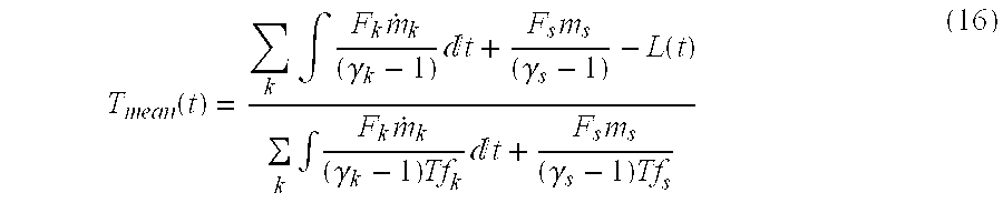
Solving equation (10) yields a value for mean temperature: T mean = i , j m ij C v ij Tf ij + m s C v s Tf s - L ( i , j m ij C v ij Tf ij + m s C v s ) . ( 11 )
Figure US06672194-20040106-M00004
Note that the summations are taken over each surface j of every charge element i with the addition of a bridge wire element s, which is assumed to burn out at t=0.
γ≡C p /C v
C p −C v =R  (12)
F=RT f
therefore,
C v =F/(γ−1)T f  (13)
Substituting into equation (10): T mean = k F k m k ( γ k - 1 ) + F s m s ( γ s - 1 ) - L k F k m k ( γ k - 1 ) Tf k + F s m s ( γ s - 1 ) Tf s ( 14 )
Figure US06672194-20040106-M00005
Which, in the limit, becomes: T mean = k F k m k ( γ k - 1 ) m k + F s m s ( γ s - 1 ) - L k F k m k ( γ k - 1 ) Tf k m k + F s m s ( γ s - 1 ) Tf s ( 15 )
Figure US06672194-20040106-M00006
and for differential weights of consumed pyrotechnic: T mean ( t ) = k F k m . k ( γ k - 1 ) t + F s m s ( γ s - 1 ) - L ( t ) k F k m . k ( γ k - 1 ) Tf k t + F s m s ( γ s - 1 ) Tf s ( 16 )
Figure US06672194-20040106-M00007
Assuming a covolume correction applied to the ideal gas law, then for gases and mixtures (assuming Noble-Abel gases & mixtures) at time t: P mean [ V free - k m k η k - m s η s ] = [ k m k R k - m s R s ] T mean ( 17 )
Figure US06672194-20040106-M00008
Using Equation 12: P mean = T mean [ k F k m k T f k + F s m s T f s ] V free - k [ m k η k - m s η s ] ( 18 )
Figure US06672194-20040106-M00009
in other words, P mean = T mean [ k ( F k T f k ) m k + F s m s T f s ] V free - k η k m k - η s m s ( 19 )
Figure US06672194-20040106-M00010
The pressure gradient in the piston actuator system will now be calculated using Lagrange approximation. Here, it is assumed that the pyrotechnic charge is entirely burned, and therefore, will be treated as a gas, with uniform distribution along the piston case (piston tube). The derivation in a tube-based reference is:
z p ≡x p +x r  (20)
where zp represents resistance pressure, xp represents piston displacement measured from the initial position, and xr represents piston barrel displacement measured from initial position.
Therefore, for one-dimensional inviscid equations of continuity and momentum (in the z direction for free motion):
δρ/δt+δ(ρv)/δz=0 (0≦z≦z p)  (21)
−1/ρδP/δz=δv/δt+δv/δz (0≦z≦z p)  (22)
assuming uniformity, i.e. δρ/δz=0, then, from equation 21:
δv/δz=−1/ρδρ/δt  (23)
and the boundary conditions are:
v(0,t)=0 v(z p ,t)=v p ≡z p  (24)
where zp and vp denote position of the piston head and piston velocity. Integrating over z yields the gas velocity distribution, i.e. v ( z , t ) = z z . p ( t ) z p ( t ) ( 25 )
Figure US06672194-20040106-M00011
where {dot over (z)}p is the first derivative of zp, with respect to time.
Substituting Equation 25 into Equation 22 yields
δP/δz=−ρ(z/z p){umlaut over (z)} p  (26)
where {umlaut over (z)}p is the second derivative of zp, with respect to time.
The all-burnt assumption implies the spatially uniform density: ρ = C i / g A b z p ( 27 )
Figure US06672194-20040106-M00012
Since, from Newton's second law, the acceleration of the piston, at any time t, is expressed as:
piston acceleration=net force on piston/piston mass  (28a)
where the propulsive force is supplied by the pressure of the pyrotechnic/propellant burning gases on the piston head, and the retarding forces are provided by the internal piston barrel resistance against the rotating band/ring, as well as air resistance against the front of the piston head as the air is compressed during piston forward movement down the piston tube. Hence, piston acceleration is expressed as: x ¨ p = [ P base - P res - P air ] A b m p / g (28b)
Figure US06672194-20040106-M00013
Therefore, substituting both equations (27) and (28b), into equation (26): P z = - z z p [ C i / g A b / z p ] [ P base - P res - P air ] A b m p / g ( 29 )
Figure US06672194-20040106-M00014
so that: P ( z , t ) = Ψ ( t ) - [ P base - P res - P air ] C i zm p z p 2 z 2 ( 30 )
Figure US06672194-20040106-M00015
The condition P(0, t)=Pchamber implies:
Ψ(t)=P chamber  (31)
so the requirement P(zp, t)=Pbase forces: P chamber = P base + 1 2 C i m p [ P base - P res - P air ] ( 32 )
Figure US06672194-20040106-M00016
into the definition: P mean = 1 z p 0 z p P ( z , t ) z ( 33 )
Figure US06672194-20040106-M00017
Equations (30) and (31) are substituted into (33) and integrated, yielding: P mean = P chamber - 1 6 C i m p [ P base - P res - P air ] ( 34 )
Figure US06672194-20040106-M00018
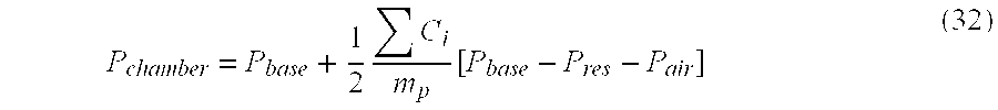
Substituting the value Pchamber from equation (32) into equation (34), and rearranging, yields: P base = 3 P mean + C i m p [ P res + P air ] 3 + C i m p ( 35 )
Figure US06672194-20040106-M00019
Therefore, according to the Lagrange model, knowledge of the propellant/pyrotechnic charge-to-piston weight ratio, the mean pressure, and the resistance pressure, is sufficient for calculating the entire pressure gradient during travel of the piston down the piston tube, and, in particular, the desired base and chamber pressures, where the pressure gradient is defined as the pressure slope, i.e., the rate of pressure rise.
While this invention has been particularly shown and described with references to preferred embodiments thereof, it will be understood by those skilled in the art that various changes in form and details may be made herein without departing from the spirit and scope of the invention as defined by the appended claims.

Claims (23)

I claim:
1. An energetic-based piston actuator comprising:
a barrel having a cylindrical interior surface;
a piston in the barrel, the piston being slidable within the barrel between an initial position and a final position, the piston having an outer diameter less than an inner diameter of the interior surface of the barrel;
a ring of malleable material about the piston and being rotatable relative to the piston; and
rifling on the interior surface of the barrel wherein the rifling engages the ring when the piston is driven in a linear direction down the barrel, the rifling deforming the malleable material of the ring so as to induce a rotational motion in the ring relative to the piston during travel of the piston between the initial position and the final position, the piston being retained by the barrel following travel.
2. The actuator of claim 1 wherein the deformation of the malleable material of the ring further induces a corresponding counter-rotation in the piston.
3. The actuator of claim 1 wherein the piston includes a body and a neck, and wherein the piston body has an outer diameter less than the inner diameter of the interior surface of the barrel, and wherein the ring is mounted about the piston neck.
4. The actuator of claim 1 wherein the rifling comprises grooves and lands formed on the interior surface of the barrel.
5. The actuator of claim 1 wherein the rifling comprises uniform twist rifling.
6. The actuator of claim 1 wherein the rifling comprises gain rifling.
7. The actuator of claim 1 wherein the piston comprises fore and aft piston heads of an outer diameter less than the inner diameter of the barrel cylinder interior surface.
8. The actuator of claim 7 wherein the ring is positioned in a groove between the fore and aft piston heads.
9. The actuator of claim 1 further comprising an energetic, which, when detonated, drives the piston and ring in a longitudinal direction down the barrel.
10. The actuator of claim 9 wherein the energetic comprises Bis-Nitro-Cobalt-3-Perchlorate.
11. The actuator of claim 9 wherein the energetic comprises a propellant or pyrotechnic.
12. The actuator of claim 1 wherein the piston and barrel have a slip-fit relationship.
13. An energetic-based actuator comprising:
a barrel having rifling on an interior cylindrical surface;
a piston in the barrel having a slip-fit relationship with the barrel, the piston having a longitudinal axis; and
a ring mounted about the piston and rotatable about the longitudinal axis of the piston;
such that when a pressure charge impinges on the piston, the piston is driven down the barrel in an axial direction along the longitudinal axis of the piston from an initial position to a final position, the axial direction of movement of the piston causing the ring to deform in the rifling, causing the ring to mesh with the rifling and to rotate relative to the piston as the piston travels in the axial direction, between the initial position and the final position, the piston being retained by the barrel following travel.
14. The actuator of claim 13 wherein the piston includes a body and a neck, and wherein the piston body has an outer diameter less than the inner diameter of the interior surface of the barrel, and wherein the ring is mounted about the piston neck.
15. The actuator of claim 13 wherein the rifling comprises grooves and lands formed on the interior surface of the barrel.
16. The actuator of claim 15 wherein the rifling comprises uniform twist rifling.
17. The actuator of claim 15 wherein the rifling comprises gain rifling.
18. The actuator of claim 13 wherein the piston comprises fore and aft piston heads of an outer diameter less than the inner diameter of the barrel cylinder interior surface.
19. The actuator of claim 18 wherein the ring is positioned in a groove between the fore and aft piston heads.
20. The actuator of claim 13 further comprising an energetic, which, when detonated, drives the piston and ring in a longitudinal direction down the barrel.
21. The actuator of claim 20 wherein the energetic comprises Bis-Nitro-Cobalt-3-Perchlorate.
22. The actuator of claim 20 wherein the energetic comprises a propellant or pyrotechnic.
23. The actuator of claim 13 wherein the ring is formed of malleable material.
US09/910,279 2001-07-19 2001-07-19 Energetic-based actuator device with rotary piston Expired - Lifetime US6672194B2 (en)

Priority Applications (7)

Application Number Priority Date Filing Date Title
US09/910,279 US6672194B2 (en) 2001-07-19 2001-07-19 Energetic-based actuator device with rotary piston
EP02752282A EP1407150B1 (en) 2001-07-19 2002-07-12 Pyrotechnical actuator device with rifled barrel
DE60208689T DE60208689T2 (en) 2001-07-19 2002-07-12 PYROTECHNIC ACTUATOR WITH A TURNED RUN
PCT/US2002/022118 WO2003008815A1 (en) 2001-07-19 2002-07-12 Pyrotechnical actuator device with rifled barrel
JP2003514127A JP3980555B2 (en) 2001-07-19 2002-07-12 Pyrotechnic actuator device having a crease cylinder
AU2002355081A AU2002355081A1 (en) 2001-07-19 2002-07-12 Pyrotechnical actuator device with rifled barrel
AT02752282T ATE315732T1 (en) 2001-07-19 2002-07-12 PYROTECHNICAL ACTUATOR WITH RIFLED BARREL

Applications Claiming Priority (1)

Application Number Priority Date Filing Date Title
US09/910,279 US6672194B2 (en) 2001-07-19 2001-07-19 Energetic-based actuator device with rotary piston

Publications (2)

Publication Number Publication Date
US20030029307A1 US20030029307A1 (en) 2003-02-13
US6672194B2 true US6672194B2 (en) 2004-01-06

Family

ID=25428564

Family Applications (1)

Application Number Title Priority Date Filing Date
US09/910,279 Expired - Lifetime US6672194B2 (en) 2001-07-19 2001-07-19 Energetic-based actuator device with rotary piston

Country Status (7)

Country Link
US (1) US6672194B2 (en)
EP (1) EP1407150B1 (en)
JP (1) JP3980555B2 (en)
AT (1) ATE315732T1 (en)
AU (1) AU2002355081A1 (en)
DE (1) DE60208689T2 (en)
WO (1) WO2003008815A1 (en)

Cited By (5)

* Cited by examiner, † Cited by third party
Publication number Priority date Publication date Assignee Title
US20090217809A1 (en) * 2005-10-28 2009-09-03 Gm Global Technology Operations, Inc. Pyrotechnic actuator with a cylinder having communicating chambers
US8534174B2 (en) 2010-09-27 2013-09-17 Power Tool Institute Pyrotechnic actuator and power cutting tool with safety reaction system having such pyrotechnic actuator
WO2014197900A1 (en) * 2013-06-07 2014-12-11 Tk Holdings Inc. Vented pressurized gas-powered actuator
WO2014197897A1 (en) * 2013-06-07 2014-12-11 Tk Holdings Inc. Vented pressurized gas-powered actuator
US10738805B2 (en) 2013-06-07 2020-08-11 Joyson Safety Systems Acquisition Llc Vented pressurized gas-powered actuator

Families Citing this family (15)

* Cited by examiner, † Cited by third party
Publication number Priority date Publication date Assignee Title
WO2005092212A1 (en) * 2004-03-29 2005-10-06 Rintek Systems Pty. Ltd. Method and apparatus for suturing
JP2007091060A (en) * 2005-09-29 2007-04-12 Toyoda Gosei Co Ltd Inflator
DE102006002209B3 (en) * 2006-01-16 2007-08-02 Stabilus Gmbh actuator
ITBS20060011A1 (en) * 2006-01-20 2007-07-21 Vittorio Piantoni ACTUATOR DEVICE
JP2007333044A (en) * 2006-06-14 2007-12-27 Daicel Chem Ind Ltd Pyro-type actuator
US7735405B2 (en) * 2008-03-14 2010-06-15 Autoliv Asp, Inc. Pyrotechnic actuator for retracting a piston
DE102008025399B4 (en) * 2008-05-28 2012-11-08 Trw Airbag Systems Gmbh Pyrotechnic drive unit
DE102008039168B4 (en) 2008-08-22 2023-06-22 Zf Airbag Germany Gmbh Pyrotechnic propulsion unit
DE102011012421A1 (en) * 2011-02-21 2012-08-23 Raimund Rerucha Clamping device, in particular for hoses
DE102011107231A1 (en) * 2011-07-13 2013-01-17 Raimund Rerucha Clamping device, in particular for hoses
US10801818B2 (en) * 2013-04-26 2020-10-13 Dana Raymond Allen Method and device for micro blasting with reusable blasting rods and electrically ignited cartridges
DE102014115397B4 (en) * 2014-10-22 2015-11-12 Peter Lell Pyrotechnic drive device
CN104564901B (en) * 2015-01-27 2016-08-24 武汉科技大学 A kind of low friction hydraulic cylinder based on miniature round pool
DE102015016193A1 (en) * 2015-12-15 2017-06-22 Trw Airbag Systems Gmbh Pyrotechnic actuator for a vehicle safety system, actuator assembly, vehicle safety system with such an actuator, and actuation methods
EP3354948B1 (en) 2017-01-25 2020-05-27 Rembe GmbH Safety + Control Rupture disc assembly with a rupture disc and an actuator for reducing the rupture pressure

Citations (49)

* Cited by examiner, † Cited by third party
Publication number Priority date Publication date Assignee Title
US887045A (en) * 1906-01-03 1908-05-05 Krupp Ag Fluid-brake for recoil-guns.
US944433A (en) * 1909-04-21 1909-12-28 Krupp Ag Fluid-brake.
US1227134A (en) * 1914-03-05 1917-05-22 Krupp Ag Device for adjusting the recoil length in fluid recoil-brakes for guns.
US1318606A (en) * 1919-10-14 Planograpii co
US1417922A (en) * 1914-02-04 1922-05-30 Alien Property Custodian Device for adjusting the recoil length of fluid brakes for gun carriages
US1803523A (en) * 1928-11-07 1931-05-05 Thomas A Conlon Recoil and counter-recoil mechanism for guns
US1861522A (en) * 1930-06-16 1932-06-07 Brandt Edgar William Projectile with automatic driving band
US2454818A (en) * 1946-03-07 1948-11-30 Victor F Lucht Gun recoil spring surge dampener
US2785632A (en) 1952-07-29 1957-03-19 Kilgore Inc Pyrotechnic device
US2975595A (en) 1958-02-06 1961-03-21 Chromalloy Corp Pressure-operated systems with ignitable propellants
US3677132A (en) * 1969-08-05 1972-07-18 Us Navy Waterproof sound, flash and recoil suppressor for firearms
US3919880A (en) * 1971-06-09 1975-11-18 Siemens Ag Method and apparatus for testing closed-end tubes in heat exchangers of nuclear reactors and the like
US3941057A (en) * 1973-04-04 1976-03-02 Hercules Incorporated Armor piercing projectile
US4005660A (en) * 1974-03-07 1977-02-01 Pichard Joseph Francis Louis J Projectiles for air arms
US4063486A (en) * 1974-05-13 1977-12-20 General Electric Company Liquid propellant weapon system
US4091621A (en) 1975-06-02 1978-05-30 Networks Electronic Corp. Pyrotechnic piston actuator
US4145971A (en) 1977-10-19 1979-03-27 Motorola, Inc. Electronic time delay safety and arming mechanism
GB2006877A (en) 1977-10-26 1979-05-10 Epitoegepgyarto Vallalat Ram Cylinder
US4187783A (en) * 1978-03-13 1980-02-12 The United States Of America As Represented By The Secretary Of The Army Discarding sabot munition
US4233902A (en) * 1978-11-24 1980-11-18 The United States Of America As Represented By The Secretary Of The Navy 76MM Rammable practice cartridge
US4263807A (en) * 1979-09-04 1981-04-28 The United States Of America As Represented By The Secretary Of The Army Gun barrel stress simulator
US4372217A (en) * 1979-04-12 1983-02-08 The United States Of America As Represented By The Secretary Of The Army Double ramp discarding sabot
US4439943A (en) * 1982-03-09 1984-04-03 Brakhage Rodney D Recoil reducer
US4479320A (en) * 1982-09-29 1984-10-30 Fix Wilbur L Cylinder lock for revolvers
US4757766A (en) * 1987-01-28 1988-07-19 Honeywell Inc. Armor-penetrating ammunition assembly with aluminum protective cap
US4802415A (en) * 1987-12-28 1989-02-07 Ford Aerospace Corporation Telescoped ammunition round having subcaliber projectile sabot with integral piston
US4850278A (en) * 1986-09-03 1989-07-25 Coors Porcelain Company Ceramic munitions projectile
US4854239A (en) 1988-10-12 1989-08-08 Honeywell Inc. Self-sterilizing safe-arm device with arm/fire feature
US5164538A (en) * 1986-02-18 1992-11-17 Twenty-First Century Research Institute Projectile having plural rotatable sections with aerodynamic air foil surfaces
US5179234A (en) * 1991-06-20 1993-01-12 Cvetanovich David A Firing chamber safety plug for revolvers
US5214237A (en) * 1990-07-09 1993-05-25 Bruce D. McArthur Fluorocarbon resin bullet and method of making same
US5259319A (en) * 1992-03-20 1993-11-09 Richard Dravecky Reusable training ammunition
US5275107A (en) 1992-06-19 1994-01-04 Alliant Techsystems Inc. Gun launched non-spinning safety and arming mechanism
US5297492A (en) * 1993-02-26 1994-03-29 Buc Steven M Armor piercing fin-stabilized discarding sabot tracer projectile
US5303631A (en) 1991-12-31 1994-04-19 Thomson-Brandt Armements Damped-action pyrotechnic actuator
US5309842A (en) * 1991-10-25 1994-05-10 Wilhelm Brenneke Kg Fabrikation Von Jagdgeschossen Device for firing a diabolo form bullet from a firearm
US5343649A (en) * 1993-09-09 1994-09-06 Petrovich Paul A Spiral recoil absorber
US5565642A (en) * 1992-03-16 1996-10-15 Mayer & Grammelspacher Dianawerk Gmbh & Co. Kg Compressed gas weapon
US5650587A (en) * 1994-08-04 1997-07-22 Royal Ordnance Plc Recoil system
US5716338A (en) * 1993-10-20 1998-02-10 Pharmacia & Upjohn Aktiebolag Dual-chamber type injection cartridge with bypass connection
US5894770A (en) * 1996-09-30 1999-04-20 Rudkin, Jr.; Henry A. Barrels for firearms and methods of manufacturing the same
US5937563A (en) * 1997-04-03 1999-08-17 Schuetz; Robert C. E. Modified firearms for firing simulated ammunition
US6067909A (en) * 1998-04-03 2000-05-30 Sabot Technologies, Inc. Sabot pressure wad
US6085660A (en) * 1998-09-10 2000-07-11 Primex Technologies, Inc. Low spin sabot
US6237497B1 (en) * 1998-04-06 2001-05-29 Rheinmetall W & M Gmbh Spin-stabilized artillery projectile having gas pressure equalizing means
US6295934B1 (en) * 1999-06-29 2001-10-02 Raytheon Company Mid-body obturator for a gun-launched projectile
US20020014076A1 (en) 2000-08-04 2002-02-07 Jeff Blackburn Pyrotechnic actuator
US6401622B1 (en) * 1998-12-02 2002-06-11 Rheinmetall W & M Gmbh Spin-stabilized artillery projectile having a metal sealing ring
US6405472B1 (en) * 2001-03-05 2002-06-18 Endre Dojcsak Gun lock safety device

Family Cites Families (1)

* Cited by examiner, † Cited by third party
Publication number Priority date Publication date Assignee Title
DE19961019C1 (en) * 1999-12-17 2001-02-22 Grammer Ag Drive device for automobile adjustable component e.g. headrest, has pyrotechnic charge detonated for displacement of piston of piston-cylinder setting device

Patent Citations (49)

* Cited by examiner, † Cited by third party
Publication number Priority date Publication date Assignee Title
US1318606A (en) * 1919-10-14 Planograpii co
US887045A (en) * 1906-01-03 1908-05-05 Krupp Ag Fluid-brake for recoil-guns.
US944433A (en) * 1909-04-21 1909-12-28 Krupp Ag Fluid-brake.
US1417922A (en) * 1914-02-04 1922-05-30 Alien Property Custodian Device for adjusting the recoil length of fluid brakes for gun carriages
US1227134A (en) * 1914-03-05 1917-05-22 Krupp Ag Device for adjusting the recoil length in fluid recoil-brakes for guns.
US1803523A (en) * 1928-11-07 1931-05-05 Thomas A Conlon Recoil and counter-recoil mechanism for guns
US1861522A (en) * 1930-06-16 1932-06-07 Brandt Edgar William Projectile with automatic driving band
US2454818A (en) * 1946-03-07 1948-11-30 Victor F Lucht Gun recoil spring surge dampener
US2785632A (en) 1952-07-29 1957-03-19 Kilgore Inc Pyrotechnic device
US2975595A (en) 1958-02-06 1961-03-21 Chromalloy Corp Pressure-operated systems with ignitable propellants
US3677132A (en) * 1969-08-05 1972-07-18 Us Navy Waterproof sound, flash and recoil suppressor for firearms
US3919880A (en) * 1971-06-09 1975-11-18 Siemens Ag Method and apparatus for testing closed-end tubes in heat exchangers of nuclear reactors and the like
US3941057A (en) * 1973-04-04 1976-03-02 Hercules Incorporated Armor piercing projectile
US4005660A (en) * 1974-03-07 1977-02-01 Pichard Joseph Francis Louis J Projectiles for air arms
US4063486A (en) * 1974-05-13 1977-12-20 General Electric Company Liquid propellant weapon system
US4091621A (en) 1975-06-02 1978-05-30 Networks Electronic Corp. Pyrotechnic piston actuator
US4145971A (en) 1977-10-19 1979-03-27 Motorola, Inc. Electronic time delay safety and arming mechanism
GB2006877A (en) 1977-10-26 1979-05-10 Epitoegepgyarto Vallalat Ram Cylinder
US4187783A (en) * 1978-03-13 1980-02-12 The United States Of America As Represented By The Secretary Of The Army Discarding sabot munition
US4233902A (en) * 1978-11-24 1980-11-18 The United States Of America As Represented By The Secretary Of The Navy 76MM Rammable practice cartridge
US4372217A (en) * 1979-04-12 1983-02-08 The United States Of America As Represented By The Secretary Of The Army Double ramp discarding sabot
US4263807A (en) * 1979-09-04 1981-04-28 The United States Of America As Represented By The Secretary Of The Army Gun barrel stress simulator
US4439943A (en) * 1982-03-09 1984-04-03 Brakhage Rodney D Recoil reducer
US4479320A (en) * 1982-09-29 1984-10-30 Fix Wilbur L Cylinder lock for revolvers
US5164538A (en) * 1986-02-18 1992-11-17 Twenty-First Century Research Institute Projectile having plural rotatable sections with aerodynamic air foil surfaces
US4850278A (en) * 1986-09-03 1989-07-25 Coors Porcelain Company Ceramic munitions projectile
US4757766A (en) * 1987-01-28 1988-07-19 Honeywell Inc. Armor-penetrating ammunition assembly with aluminum protective cap
US4802415A (en) * 1987-12-28 1989-02-07 Ford Aerospace Corporation Telescoped ammunition round having subcaliber projectile sabot with integral piston
US4854239A (en) 1988-10-12 1989-08-08 Honeywell Inc. Self-sterilizing safe-arm device with arm/fire feature
US5214237A (en) * 1990-07-09 1993-05-25 Bruce D. McArthur Fluorocarbon resin bullet and method of making same
US5179234A (en) * 1991-06-20 1993-01-12 Cvetanovich David A Firing chamber safety plug for revolvers
US5309842A (en) * 1991-10-25 1994-05-10 Wilhelm Brenneke Kg Fabrikation Von Jagdgeschossen Device for firing a diabolo form bullet from a firearm
US5303631A (en) 1991-12-31 1994-04-19 Thomson-Brandt Armements Damped-action pyrotechnic actuator
US5565642A (en) * 1992-03-16 1996-10-15 Mayer & Grammelspacher Dianawerk Gmbh & Co. Kg Compressed gas weapon
US5259319A (en) * 1992-03-20 1993-11-09 Richard Dravecky Reusable training ammunition
US5275107A (en) 1992-06-19 1994-01-04 Alliant Techsystems Inc. Gun launched non-spinning safety and arming mechanism
US5297492A (en) * 1993-02-26 1994-03-29 Buc Steven M Armor piercing fin-stabilized discarding sabot tracer projectile
US5343649A (en) * 1993-09-09 1994-09-06 Petrovich Paul A Spiral recoil absorber
US5716338A (en) * 1993-10-20 1998-02-10 Pharmacia & Upjohn Aktiebolag Dual-chamber type injection cartridge with bypass connection
US5650587A (en) * 1994-08-04 1997-07-22 Royal Ordnance Plc Recoil system
US5894770A (en) * 1996-09-30 1999-04-20 Rudkin, Jr.; Henry A. Barrels for firearms and methods of manufacturing the same
US5937563A (en) * 1997-04-03 1999-08-17 Schuetz; Robert C. E. Modified firearms for firing simulated ammunition
US6067909A (en) * 1998-04-03 2000-05-30 Sabot Technologies, Inc. Sabot pressure wad
US6237497B1 (en) * 1998-04-06 2001-05-29 Rheinmetall W & M Gmbh Spin-stabilized artillery projectile having gas pressure equalizing means
US6085660A (en) * 1998-09-10 2000-07-11 Primex Technologies, Inc. Low spin sabot
US6401622B1 (en) * 1998-12-02 2002-06-11 Rheinmetall W & M Gmbh Spin-stabilized artillery projectile having a metal sealing ring
US6295934B1 (en) * 1999-06-29 2001-10-02 Raytheon Company Mid-body obturator for a gun-launched projectile
US20020014076A1 (en) 2000-08-04 2002-02-07 Jeff Blackburn Pyrotechnic actuator
US6405472B1 (en) * 2001-03-05 2002-06-18 Endre Dojcsak Gun lock safety device

Non-Patent Citations (1)

* Cited by examiner, † Cited by third party
Title
U.S. SIR H1365, Amspacker et al., Nov. 1994. *

Cited By (10)

* Cited by examiner, † Cited by third party
Publication number Priority date Publication date Assignee Title
US20090217809A1 (en) * 2005-10-28 2009-09-03 Gm Global Technology Operations, Inc. Pyrotechnic actuator with a cylinder having communicating chambers
US20120204562A1 (en) * 2005-10-28 2012-08-16 GM Global Technology Operations LLC Pyrotechnic actuator with a cylinder having communicating chambers
US8549975B2 (en) 2005-10-28 2013-10-08 GM Global Technology Operations LLC Pyrotechnic actuator with a cylinder having communicating chambers
US8596180B2 (en) * 2005-10-28 2013-12-03 GM Global Technology Operations LLC Pyrotechnic actuator with a cylinder having communicating chambers
US8534174B2 (en) 2010-09-27 2013-09-17 Power Tool Institute Pyrotechnic actuator and power cutting tool with safety reaction system having such pyrotechnic actuator
WO2014197900A1 (en) * 2013-06-07 2014-12-11 Tk Holdings Inc. Vented pressurized gas-powered actuator
WO2014197897A1 (en) * 2013-06-07 2014-12-11 Tk Holdings Inc. Vented pressurized gas-powered actuator
US9657755B2 (en) 2013-06-07 2017-05-23 Tk Holdings Inc. Vented pressurized gas-powered actuator
US9739294B2 (en) 2013-06-07 2017-08-22 Tk Holdings Inc. Vented pressurized gas-powered actuator
US10738805B2 (en) 2013-06-07 2020-08-11 Joyson Safety Systems Acquisition Llc Vented pressurized gas-powered actuator

Also Published As

Publication number Publication date
DE60208689T2 (en) 2006-09-14
AU2002355081A1 (en) 2003-03-03
EP1407150A1 (en) 2004-04-14
JP2004536261A (en) 2004-12-02
EP1407150B1 (en) 2006-01-11
WO2003008815A8 (en) 2003-03-13
JP3980555B2 (en) 2007-09-26
DE60208689D1 (en) 2006-04-06
US20030029307A1 (en) 2003-02-13
ATE315732T1 (en) 2006-02-15
WO2003008815A1 (en) 2003-01-30

Similar Documents

Publication Publication Date Title
US6672194B2 (en) Energetic-based actuator device with rotary piston
US3106131A (en) Cartridge actuated device
CA2826664A1 (en) Pressure wave generator with movable control rod for generating a pressure wave in a medium
Denny The internal ballistics of an air gun
US20040107826A1 (en) Safer munitions with enhanced velocity
KR830006672A (en) Explosives fasteners
US4964341A (en) Projectile with ram air-extendible probe and ram air-extendible probe assembly therefor
US6983698B1 (en) Shaped charge explosive device and method of making same
US3418878A (en) Method and means for augmenting hypervelocity flight
JPH0371640B2 (en)
US5303632A (en) Projectile propelling system
Bogdanov Pulse increase at mass interaction in an energy carrier
JPH0672755B2 (en) Gas generator missile launch system
Bogdanoff et al. Improving the performance of two-stage gas guns by adding a diaphragm in the pump tube
Li et al. Research on the optimum length–diameter ratio of the charge of a multimode warhead
Bykov et al. Evolutionary method for combined ballistic launchers structural and parametric optimization
US7753040B2 (en) Helical field accelerator
Bioletti et al. A high-velocity gun employing a shock-compressed light gas
SU583291A1 (en) Working member of percussive device
WO2014146170A1 (en) Projectile with rotational motion
Oberle et al. Methods for determining burning or gas generation rates of plasma-augmented propellants with applications to electrothermal-chemical (ETC) guns
Wilson et al. The blast wave accelerator—Feasibility study
US6349628B1 (en) Helix thruster
Zielinski et al. Mass stabilized projectile designs for electromagnetic launch
Khristenko Problem of increasing the survivability of two–stage ballistic guns

Legal Events

Date Code Title Description
AS Assignment

Owner name: TEXTRON SYSTEMS CORPORATION, MASSACHUSETTS

Free format text: ASSIGNMENT OF ASSIGNORS INTEREST;ASSIGNOR:DAOUD, SAMI;REEL/FRAME:012011/0177

Effective date: 20010711

STCF Information on status: patent grant

Free format text: PATENTED CASE

AS Assignment

Owner name: TEXTRON INNOVATIONS INC., RHODE ISLAND

Free format text: ASSIGNMENT OF ASSIGNORS INTEREST;ASSIGNORS:TEXTRON SYSTEMS CORPORATION;TEXTRON SYSTEMS RHODE ISLAND (2001) INC.;REEL/FRAME:015167/0016

Effective date: 20021101

FPAY Fee payment

Year of fee payment: 4

FPAY Fee payment

Year of fee payment: 8

FPAY Fee payment

Year of fee payment: 12