US6683534B2 - Vehicle seat occupant detection system with seat cushion identifying transponder - Google Patents
Vehicle seat occupant detection system with seat cushion identifying transponder Download PDFInfo
- Publication number
- US6683534B2 US6683534B2 US10/159,661 US15966102A US6683534B2 US 6683534 B2 US6683534 B2 US 6683534B2 US 15966102 A US15966102 A US 15966102A US 6683534 B2 US6683534 B2 US 6683534B2
- Authority
- US
- United States
- Prior art keywords
- seat
- identification data
- signal
- seat identification
- electromagnetic signal
- Prior art date
- Legal status (The legal status is an assumption and is not a legal conclusion. Google has not performed a legal analysis and makes no representation as to the accuracy of the status listed.)
- Expired - Lifetime, expires
Links
- 238000001514 detection method Methods 0.000 title claims abstract description 40
- 230000003213 activating effect Effects 0.000 claims abstract description 10
- 238000000034 method Methods 0.000 abstract description 5
- 230000008569 process Effects 0.000 abstract description 5
- 238000009795 derivation Methods 0.000 abstract description 3
- 230000004913 activation Effects 0.000 abstract 1
- 238000001994 activation Methods 0.000 abstract 1
- 238000004891 communication Methods 0.000 description 7
- 230000005540 biological transmission Effects 0.000 description 5
- 239000012530 fluid Substances 0.000 description 5
- 230000007613 environmental effect Effects 0.000 description 3
- 239000006261 foam material Substances 0.000 description 3
- 230000009471 action Effects 0.000 description 2
- 230000008859 change Effects 0.000 description 2
- 238000010586 diagram Methods 0.000 description 2
- 239000003990 capacitor Substances 0.000 description 1
- 230000007547 defect Effects 0.000 description 1
- 230000000694 effects Effects 0.000 description 1
- 239000004744 fabric Substances 0.000 description 1
- 239000006260 foam Substances 0.000 description 1
- 238000004519 manufacturing process Methods 0.000 description 1
- 230000001105 regulatory effect Effects 0.000 description 1
- 230000008439 repair process Effects 0.000 description 1
- 230000004044 response Effects 0.000 description 1
- 238000000926 separation method Methods 0.000 description 1
Images


Classifications
-
- B—PERFORMING OPERATIONS; TRANSPORTING
- B60—VEHICLES IN GENERAL
- B60R—VEHICLES, VEHICLE FITTINGS, OR VEHICLE PARTS, NOT OTHERWISE PROVIDED FOR
- B60R21/00—Arrangements or fittings on vehicles for protecting or preventing injuries to occupants or pedestrians in case of accidents or other traffic risks
- B60R21/01—Electrical circuits for triggering passive safety arrangements, e.g. airbags, safety belt tighteners, in case of vehicle accidents or impending vehicle accidents
- B60R21/015—Electrical circuits for triggering passive safety arrangements, e.g. airbags, safety belt tighteners, in case of vehicle accidents or impending vehicle accidents including means for detecting the presence or position of passengers, passenger seats or child seats, and the related safety parameters therefor, e.g. speed or timing of airbag inflation in relation to occupant position or seat belt use
- B60R21/01512—Passenger detection systems
- B60R21/01516—Passenger detection systems using force or pressure sensing means
-
- B—PERFORMING OPERATIONS; TRANSPORTING
- B60—VEHICLES IN GENERAL
- B60N—SEATS SPECIALLY ADAPTED FOR VEHICLES; VEHICLE PASSENGER ACCOMMODATION NOT OTHERWISE PROVIDED FOR
- B60N2/00—Seats specially adapted for vehicles; Arrangement or mounting of seats in vehicles
- B60N2/002—Seats provided with an occupancy detection means mounted therein or thereon
-
- B—PERFORMING OPERATIONS; TRANSPORTING
- B60—VEHICLES IN GENERAL
- B60R—VEHICLES, VEHICLE FITTINGS, OR VEHICLE PARTS, NOT OTHERWISE PROVIDED FOR
- B60R21/00—Arrangements or fittings on vehicles for protecting or preventing injuries to occupants or pedestrians in case of accidents or other traffic risks
- B60R21/01—Electrical circuits for triggering passive safety arrangements, e.g. airbags, safety belt tighteners, in case of vehicle accidents or impending vehicle accidents
- B60R21/015—Electrical circuits for triggering passive safety arrangements, e.g. airbags, safety belt tighteners, in case of vehicle accidents or impending vehicle accidents including means for detecting the presence or position of passengers, passenger seats or child seats, and the related safety parameters therefor, e.g. speed or timing of airbag inflation in relation to occupant position or seat belt use
- B60R21/01512—Passenger detection systems
- B60R21/01544—Passenger detection systems detecting seat belt parameters, e.g. length, tension or height-adjustment
- B60R21/01546—Passenger detection systems detecting seat belt parameters, e.g. length, tension or height-adjustment using belt buckle sensors
-
- B—PERFORMING OPERATIONS; TRANSPORTING
- B60—VEHICLES IN GENERAL
- B60R—VEHICLES, VEHICLE FITTINGS, OR VEHICLE PARTS, NOT OTHERWISE PROVIDED FOR
- B60R21/00—Arrangements or fittings on vehicles for protecting or preventing injuries to occupants or pedestrians in case of accidents or other traffic risks
- B60R21/01—Electrical circuits for triggering passive safety arrangements, e.g. airbags, safety belt tighteners, in case of vehicle accidents or impending vehicle accidents
- B60R2021/01122—Prevention of malfunction
- B60R2021/01184—Fault detection or diagnostic circuits
- B60R2021/01197—Warning devices
-
- B—PERFORMING OPERATIONS; TRANSPORTING
- B60—VEHICLES IN GENERAL
- B60R—VEHICLES, VEHICLE FITTINGS, OR VEHICLE PARTS, NOT OTHERWISE PROVIDED FOR
- B60R21/00—Arrangements or fittings on vehicles for protecting or preventing injuries to occupants or pedestrians in case of accidents or other traffic risks
- B60R21/01—Electrical circuits for triggering passive safety arrangements, e.g. airbags, safety belt tighteners, in case of vehicle accidents or impending vehicle accidents
- B60R21/015—Electrical circuits for triggering passive safety arrangements, e.g. airbags, safety belt tighteners, in case of vehicle accidents or impending vehicle accidents including means for detecting the presence or position of passengers, passenger seats or child seats, and the related safety parameters therefor, e.g. speed or timing of airbag inflation in relation to occupant position or seat belt use
- B60R21/01512—Passenger detection systems
- B60R21/01544—Passenger detection systems detecting seat belt parameters, e.g. length, tension or height-adjustment
- B60R21/0155—Passenger detection systems detecting seat belt parameters, e.g. length, tension or height-adjustment sensing belt tension
Definitions
- the technical field of this invention is a seat occupant detection system for a vehicle.
- Vehicle seat occupant detection systems are used to help decide whether or how to deploy an airbag in a crash event.
- At least one such system provides an occupant characteristic sensor in a vehicle seat member to determine the weight of a seat occupant. The determination is made by a programmed computer provided in an occupant detection system module, the computer having an input connection from a seat characteristic sensor such as a fluid pressure sensor connected to a fluid filled bladder on the seat pan under the bottom seat cushion member.
- the output signal from the sensor is compared with seat calibration data, typically including calibrated threshold values, to characterize a detected seat occupant.
- the seat calibration data are initially determined in calibration tests of the occupant detection system, which includes the seat cushion member, bladder, sensor and occupant detection system module, and are typically stored in rewritable, non-volatile memory such as EEPROM in the occupant detection system module.
- rewritable, non-volatile memory such as EEPROM in the occupant detection system module.
- seat cushion members are generally made of a synthetic foam material that can change its force or pressure transfer characteristics with age and/or environmental variables
- the use of the rewritable, non-volatile memory allows updating of the seat calibration data during vehicle operation, service or recalibration.
- the vehicle manufacturer may direct that the system be replaced only by a complete, calibrated system that includes seat cushion member, bladder, sensor and occupant detection system module storing seat calibration data for the replacement seat cushion member.
- a vehicle seat cushion has a transponder responsive to a transponder activating signal to generate an electromagnetic signal containing unique seat identification data.
- Sensing apparatus is responsive to a characteristic of the vehicle seat cushion to generate a seat characteristic signal thereof; and an occupant detection module is responsive to the seat characteristic signal to derive a seat occupant signal and has a dedicated memory location for seat identification data in a rewritable, non-volatile memory.
- the occupant detection module generates the transponder activating signal, receives and processes the electromagnetic signal to derive the seat identification data therefrom and compares the seat identification data from the electromagnetic signal with seat identification data in the dedicated memory location. If the seat identification data from the electromagnetic signal does not match the seat identification data in the dedicated memory location, the occupant detection module generates a warning signal and preferably prevents derivation of the seat occupant signal.
- the occupant detection module further determines if there is seat identification data in the dedicated memory location and, if there is no seat identification data in the rewritable, non-volatile memory, copies the seat identification data from the electromagnetic signal to the dedicated memory location.
- a vehicle seat cushion has a transponder responsive to a transponder activating signal to generate an electromagnetic signal containing unique seat identification data.
- Sensing apparatus is responsive to a characteristic of the vehicle seat cushion to generate a seat characteristic signal thereof; and an occupant detection module is responsive to the seat characteristic signal to derive a seat occupant signal and has a dedicated memory location for seat identification data in a rewritable, non-volatile memory.
- the occupant detection module further generates the transponder activating signal, receives and processes the electromagnetic signal to derive the seat identification data therefrom and determines if there is seat identification data in the dedicated memory location.
- the occupant detection module determines if the seat identification data from the electromagnetic signal matches seat identification data from a previously received electromagnetic signal and, if so, increments a count and stores the seat identification data from the electromagnetic signal as the seat identification data from a previously received electromagnetic signal. If the count exceeds a predetermined reference value, the seat identification data from the electromagnetic signal is copied to the dedicated memory location. But if there is seat identification data in the dedicated memory location, the occupant detection system module compares seat identification data from the electromagnetic signal with seat identification data in the dedicated memory location. If the seat identification data from the electromagnetic signal does not match the seat identification data in the dedicated memory location, the occupant detection module generates a warning signal and preferably prevents derivation of the seat occupant signal.
- FIG. 1 is a block diagram of a vehicle occupant protection system with a vehicle occupant detection system according to this invention.
- FIG. 2 is a schematic diagram of a portion of the system of FIG. 1 .
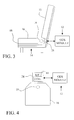
- FIGS. 3 and 4 respectively show left side and top views of a vehicle seat having an occupant detection system as shown in FIGS. 1 and 2.
- FIGS. 5 and 6 A- 6 C show flow charts illustrating the operation of the system of FIGS. 1 - 4 .
- a vehicle occupant protection system as shown in FIG. 1, comprises an airbag control module (ACM) 10 that receives signals from crash sensors, not shown, and provides deploy signals as required to restraints, not shown, such as airbags.
- the crash sensors and airbags may be any such articles known in the art for use in vehicle restraint systems.
- a vehicle seat 14 is provided with a seat cushion member 16 , generally comprising a shaped block of foam material providing a comfortable seating support, usually covered in a fabric for appearance, comfort and protection.
- a bladder 18 packaged with seat cushion member 16 is typically located under seat cushion member 16 but above a seat pan member, not shown, and is filled with a non-compressible fluid so as to generate a pressure in the fluid in response to the weight of a seat occupant on the seat cushion member.
- the pressure in the fluid is sensed by a pressure sensor 20 that, together with bladder 18 , forms a seat characteristic sensor apparatus providing an output seat characteristic signal of the weight born by seat cushion member 16 .
- This signal is provided to an occupant detection system (ODS) module 12 including a computer programmed to determine a seat occupant signal characterizing the occupancy status of the seat according to predetermined, stored calibrated classification threshold values.
- ODS occupant detection system
- ACM 10 and ODS module 12 are adapted to communicate with each other over a communication bus 26 , such as a standard vehicle communication bus, which also permits communication with other modules in the vehicle having memory.
- each system is calibrated after assembly with a particular seat cushion member; and the calibrated threshold values are stored in memory within ODS module 12 .
- These parameters may be changed by the ODS module during subsequent vehicle operation as characteristics change over time.
- seat foam material changes its physical characteristics with age and is also subject to changes with environmental parameters.
- one or more objects of predetermined weight and shape are dropped in a predetermined manner onto the installed seat cushion member to generate pressure readings for storage as the calibrated threshold values for determining the boundaries between occupant classifications.
- these calibrated threshold values must always be present for use; and it is also desired that they be updated as required to compensate for variations in physical and environmental seat characteristics over time. Since the values are calibrated with respect to a particular seat cushion, they must stay with that seat cushion.
- the vehicle manufacturer may require that any defect in the occupant detection system requiring replacement be accomplished through replacement of an entire occupant detection system, including at least seat cushion and an ODS module in a precalibrated combination.
- the apparatus of this embodiment provides an identifying transponder 19 in seat cushion 16 and a reader/exciter apparatus 28 with input and output connections to ODS module 12 .
- ODS module 12 and reader/exciter apparatus 28 are shown in greater detail in FIG. 2 .
- ODS module 12 includes a microprocessor based digital computer 30 that includes memory, both RAM and a rewritable, non-volatile memory such as EEPROM for storing the calibrated threshold values.
- Reader/exciter apparatus 28 includes a reader/exciter chip 40 connected through interface (I/F) blocks 46 and 48 to communicate digital data with computer 30 .
- a regulated power supply chip 32 in ODS module 12 provides the required power for ODS 12 and reader/exciter 28 .
- Reader/exciter 28 also includes a coil 44 connected with reader/exciter chip 40 to serve in a power transmission mode as the primary of an output transformer and, alternatively, in a communication mode as an RF transmitting and receiving antenna.
- FIGS. 3 and 4 show two views of seat cushion 16 to illustrate the spatial relationship between transponder 19 embedded therein and reader/exciter apparatus 28 with coil 44 .
- FIG. 3 is a side view of seat 14 showing seat cushion 16 atop bladder 18 .
- Reader/exciter apparatus 28 is supported on seat 14 with its coil 44 near the rear of seat cushion 16 in close proximity to embedded transponder 19 , which includes a coil of its own that is oriented relative to coil 44 to permit efficient transformer action at low frequencies and efficient RF communication at high frequencies.
- FIG. 4 shows a top view of seat cushion 16 , rotated 90 degrees counter-clockwise, to show that transponder 19 in the seat cushion and reader/exciter apparatus with coil 44 are in close proximity at the middle of a rear surface of seat cushion 28 .
- transponder 19 This rear location for transponder 19 is generally under the seat back cushion 15 and is thus generally subject to low physical stress for the protection of the transponder.
- the close proximity is required for efficient transmission of electrical power from reader/exciter 28 to transponder 19 in power transmission mode and to allow low power during RF transmissions and thus reduce unwanted RF emissions.
- the reader/exciter and transponder combination is a known and existing apparatus for providing communication between a first electronic unit having an electric power source and a second electronic unit having no permanent electric power source.
- reader/exciter apparatus first operates in power transmission mode by providing low frequency AC current in coil 44 , acting as a transformer primary coil to a secondary coil in transponder 19 and charging up a charge storage device therein such as a capacitor.
- Transponder 19 is then able to operate using this charge as electric power for a time sufficient to transmit the unique identifying data therein back through its own coil used as a transmitting antenna to coil 44 , which receives the RF message, demodulates it for the digital code and provides the latter to microprocessor 30 of ODS 12 .
- FIGS. 5 and 6 A- 6 C illustrate the operation of the system in greater detail.
- Microprocessor 30 of ODS 12 runs a routine OCCUPANT STATUS on a regular basis, for example every 100 milliseconds, to determine an occupant status of seat 14 and generate therefrom a seat occupant signal.
- this routine begins at step 100 by reading the A/D and discrete inputs used in occupant classification.
- reader/exciter 102 is signalled to activate transponder 19 as described above.
- a subroutine PERFORM DIAGNOSTICS is called at step 106 ; and the determination of occupant weight and classification is performed in the remainder of the routine 108 in a manner known in the art.
- FIGS. 6A-6C illustrate the operation of subroutine PERFORM DIAGNOSTICS.
- the routine begins by determining if an SFS message containing seat cushion identification data has been received as indicated by flag SFS DATA RCVD. If this flag is not TRUE, the subroutine returns to routine OCCUPANT STATUS. But if the SFS DATA RCVD flag is TRUE, the subroutine determines at step 122 if there is SFS ID data in rewritable non-volatile memory within ODS module 12 . If there is, the SFS ID data in ODS memory is compared with the seat cushion identification data in the SFS message at step 124 . If there is match, an SFS error count is reset at step 128 ; if there is no match, the SFS error count is alternatively incremented at step 126 .
- step 150 the routine resets the SFS DATA RCVD flag to FALSE; and the SFS message is cleared from RAM at step 152 .
- step 154 if the SFS ERROR count does not exceed a predetermined reference limit count KE, the subroutine returns to the routine OCCUPANT STATUS and an seat occupant signal is generated in the normal manner. But if the SFS ERROR count exceeds limit count KE, the subroutine sets an SFS FAULT flag at step 156 and disables the ODS algorithm at step 158 before exiting. The effect of the latter is determined by the requirements of the system but will typically be to prevent restraint deployment and provide an indication to the vehicle operator that service is required.
- step 130 the subroutine determines if the data in the SFS message is the same as that stored from the previous loop of the subroutine and increments an SFS message count at step 132 if it is the same. If it is not the same, the SFS message count is reset at step 134 to an initial value such as zero.
- the subroutine next copies the present SFS message data to the RAM memory location of the previous SFS message at step 136 to replace the previous value, resets the SFS DATA RCVD flag to FALSE at step 138 and clears the SFS message at step 140 .
- the SFS message count is then compared with a predetermined reference KP at step 142 ; and, if the count exceeds KP, the SFS Message data is copied to the SFS ID location in rewritable, non-volatile memory at step 144 . This provides for matching a new ODS module to a vehicle seat cushion in manufacture or repair. From step 144 , or from step 142 if the SFS message count does not exceed KP, the subroutine returns to the routine OCCUPANT STATUS.
Abstract
Description
Claims (6)
Priority Applications (1)
| Application Number | Priority Date | Filing Date | Title |
|---|---|---|---|
| US10/159,661 US6683534B2 (en) | 2002-05-31 | 2002-05-31 | Vehicle seat occupant detection system with seat cushion identifying transponder |
Applications Claiming Priority (1)
| Application Number | Priority Date | Filing Date | Title |
|---|---|---|---|
| US10/159,661 US6683534B2 (en) | 2002-05-31 | 2002-05-31 | Vehicle seat occupant detection system with seat cushion identifying transponder |
Publications (2)
| Publication Number | Publication Date |
|---|---|
| US20030222767A1 US20030222767A1 (en) | 2003-12-04 |
| US6683534B2 true US6683534B2 (en) | 2004-01-27 |
Family
ID=29582981
Family Applications (1)
| Application Number | Title | Priority Date | Filing Date |
|---|---|---|---|
| US10/159,661 Expired - Lifetime US6683534B2 (en) | 2002-05-31 | 2002-05-31 | Vehicle seat occupant detection system with seat cushion identifying transponder |
Country Status (1)
| Country | Link |
|---|---|
| US (1) | US6683534B2 (en) |
Cited By (15)
| Publication number | Priority date | Publication date | Assignee | Title |
|---|---|---|---|---|
| US20040068357A1 (en) * | 2002-10-02 | 2004-04-08 | Shinichi Kiribayashi | Vehicle occupant detection apparatus providing status information concerning occupant of vehicle seat |
| US20040243295A1 (en) * | 2003-04-23 | 2004-12-02 | Thomas Fischer | Occupant recognition system for vehicles |
| US20050275258A1 (en) * | 2004-06-07 | 2005-12-15 | Patterson James F | Child restraint system and method for monitoring installation of the child restraint system |
| US20050275276A1 (en) * | 2004-06-07 | 2005-12-15 | Patterson James F | Child restraint system and method for monitoring installation of the child restraint system |
| US20060049929A1 (en) * | 2004-09-08 | 2006-03-09 | Lawrence Rodney A | Child restraint system with in-motion belt status monitoring |
| US20060111821A1 (en) * | 2004-08-09 | 2006-05-25 | Wallner Edward J | Child restraint system comprising event data recorder, and method for providing data relating to installation or adjustment |
| US20060180371A1 (en) * | 2000-09-08 | 2006-08-17 | Automotive Technologies International, Inc. | System and Method for In-Vehicle Communications |
| US20070022829A1 (en) * | 1998-04-01 | 2007-02-01 | Methode Electronics, Inc. | Sensor pad for controlling airbag deployment and associated support |
| US20070126561A1 (en) * | 2000-09-08 | 2007-06-07 | Automotive Technologies International, Inc. | Integrated Keyless Entry System and Vehicle Component Monitoring |
| US20070139185A1 (en) * | 2005-12-15 | 2007-06-21 | Lear Corporation | Rfid systems for vehicular applications |
| US20080033691A1 (en) * | 2006-05-17 | 2008-02-07 | Claude Launay | Method for improving the localisation of a target in regard of a sensor |
| US7403845B2 (en) | 2004-06-07 | 2008-07-22 | Delphi Technologies, Inc. | Child seat monitoring system and method for determining a type of child seat |
| US20080319697A1 (en) * | 2007-06-19 | 2008-12-25 | Gray Charles A | System and method for determining an amount of pressure applied by an occupant on a vehicle seat |
| US20100117845A1 (en) * | 2008-11-11 | 2010-05-13 | Armin Satz | Method and Device for Sensing a Body |
| CN105307904A (en) * | 2013-06-12 | 2016-02-03 | 博世株式会社 | Control device that controls protection device for protecting vehicle passenger or pedestrian, and control system |
Families Citing this family (5)
| Publication number | Priority date | Publication date | Assignee | Title |
|---|---|---|---|---|
| US20080136227A1 (en) * | 2006-12-11 | 2008-06-12 | 3M Innovative Properties Company | Vehicle seat sensor assembly |
| US8477039B2 (en) * | 2007-05-18 | 2013-07-02 | Geoat, Inc. | Providing information related to the posture mode of a user applying pressure to a seat component |
| US20150015399A1 (en) * | 2013-07-01 | 2015-01-15 | Geost, Inc. | Providing information related to the posture mode of a user appplying pressure to a seat component |
| EP3561719A1 (en) * | 2018-04-25 | 2019-10-30 | Ningbo Geely Automobile Research & Development Co., Ltd. | Vehicle occupant management system and method |
| US20220097637A1 (en) * | 2020-09-30 | 2022-03-31 | Littelfuse, Inc. | Wireless sensor array for occupancy detection in passenger vehicles |
Citations (5)
| Publication number | Priority date | Publication date | Assignee | Title |
|---|---|---|---|---|
| US5515933A (en) * | 1994-03-23 | 1996-05-14 | Mercedes-Benz Ag | Device for recognizing a child's seat which is strapped to the front passenger's seat of a motor vehicle |
| US5948031A (en) * | 1996-02-23 | 1999-09-07 | Nec Technologies, Inc. | Vehicle passenger sensing system and method |
| US6161070A (en) * | 1996-02-23 | 2000-12-12 | Nec Home Electronics, Inc. | Passenger detection system |
| US6329913B1 (en) * | 1999-10-05 | 2001-12-11 | Nec Technologies, Inc. | Passenger detection system and method |
| US6345840B1 (en) * | 1999-02-10 | 2002-02-12 | Daimlerchrysler Ag | Vehicle seat having a seat face element and adjustable backrest element |
-
2002
- 2002-05-31 US US10/159,661 patent/US6683534B2/en not_active Expired - Lifetime
Patent Citations (5)
| Publication number | Priority date | Publication date | Assignee | Title |
|---|---|---|---|---|
| US5515933A (en) * | 1994-03-23 | 1996-05-14 | Mercedes-Benz Ag | Device for recognizing a child's seat which is strapped to the front passenger's seat of a motor vehicle |
| US5948031A (en) * | 1996-02-23 | 1999-09-07 | Nec Technologies, Inc. | Vehicle passenger sensing system and method |
| US6161070A (en) * | 1996-02-23 | 2000-12-12 | Nec Home Electronics, Inc. | Passenger detection system |
| US6345840B1 (en) * | 1999-02-10 | 2002-02-12 | Daimlerchrysler Ag | Vehicle seat having a seat face element and adjustable backrest element |
| US6329913B1 (en) * | 1999-10-05 | 2001-12-11 | Nec Technologies, Inc. | Passenger detection system and method |
Cited By (41)
| Publication number | Priority date | Publication date | Assignee | Title |
|---|---|---|---|---|
| US20070022829A1 (en) * | 1998-04-01 | 2007-02-01 | Methode Electronics, Inc. | Sensor pad for controlling airbag deployment and associated support |
| US8151654B2 (en) | 1998-04-01 | 2012-04-10 | Methode Electronics, Inc. | Sensor pad for controlling airbag deployment and associated support |
| US20080129475A1 (en) * | 2000-09-08 | 2008-06-05 | Automotive Technologies International, Inc. | System and Method for In-Vehicle Communications |
| US7313467B2 (en) | 2000-09-08 | 2007-12-25 | Automotive Technologies International Inc. | System and method for in-vehicle communications |
| US7444210B2 (en) | 2000-09-08 | 2008-10-28 | Automotive Technologies International, Inc. | System and method for in-vehicle communications |
| US20070126561A1 (en) * | 2000-09-08 | 2007-06-07 | Automotive Technologies International, Inc. | Integrated Keyless Entry System and Vehicle Component Monitoring |
| US20060180371A1 (en) * | 2000-09-08 | 2006-08-17 | Automotive Technologies International, Inc. | System and Method for In-Vehicle Communications |
| US7039503B2 (en) * | 2002-10-02 | 2006-05-02 | Denso Corporation | Vehicle occupant detection apparatus providing status information concerning occupant of vehicle seat |
| US20040068357A1 (en) * | 2002-10-02 | 2004-04-08 | Shinichi Kiribayashi | Vehicle occupant detection apparatus providing status information concerning occupant of vehicle seat |
| US20040243295A1 (en) * | 2003-04-23 | 2004-12-02 | Thomas Fischer | Occupant recognition system for vehicles |
| US7181324B2 (en) | 2003-04-23 | 2007-02-20 | Delphi Technologies, Inc. | Occupant recognition system for vehicles |
| US20050280297A1 (en) * | 2004-06-07 | 2005-12-22 | Patterson James F | Child seat and monitoring system |
| US20050275276A1 (en) * | 2004-06-07 | 2005-12-15 | Patterson James F | Child restraint system and method for monitoring installation of the child restraint system |
| US7478875B2 (en) | 2004-06-07 | 2009-01-20 | Delphi Technologies, Inc. | Child restraint system and method for monitoring installation of the child restraint system |
| US20060006713A1 (en) * | 2004-06-07 | 2006-01-12 | Patterson James F | Child seat and monitoring system |
| US7385520B2 (en) | 2004-06-07 | 2008-06-10 | Delphi Technologies, Inc. | Child restraint system comprising weight sensor |
| US7188898B2 (en) | 2004-06-07 | 2007-03-13 | Delphi Technologies, Inc. | Child restraint system comprising control unit for evaluating harness adjustment |
| US7224270B2 (en) | 2004-06-07 | 2007-05-29 | Delphi Technologies, Inc. | Child seat and monitoring system |
| US20050275258A1 (en) * | 2004-06-07 | 2005-12-15 | Patterson James F | Child restraint system and method for monitoring installation of the child restraint system |
| US20050275260A1 (en) * | 2004-06-07 | 2005-12-15 | Patterson James F | Child restraint system comprising control unit for evaluating harness adjustment |
| US7403845B2 (en) | 2004-06-07 | 2008-07-22 | Delphi Technologies, Inc. | Child seat monitoring system and method for determining a type of child seat |
| US20050275554A1 (en) * | 2004-06-07 | 2005-12-15 | Patterson James F | Child restraint system comprising weight sensor |
| US7422283B2 (en) | 2004-06-07 | 2008-09-09 | Delphi Technologies, Inc. | Child restraint system and method for monitoring installation of the child restraint system |
| US7439866B2 (en) | 2004-08-09 | 2008-10-21 | Delphi Technologies, Inc. | Child restraint system comprising event data recorder, and method for providing data relating to installation or adjustment |
| US20060111821A1 (en) * | 2004-08-09 | 2006-05-25 | Wallner Edward J | Child restraint system comprising event data recorder, and method for providing data relating to installation or adjustment |
| US20060057900A1 (en) * | 2004-09-08 | 2006-03-16 | Lawrence Rodney A | Apparatus and method for interconnecting a child seat and monitoring system |
| US20060049677A1 (en) * | 2004-09-08 | 2006-03-09 | Lawrence Rodney A | Child restraint system |
| US7410212B2 (en) | 2004-09-08 | 2008-08-12 | Delphi Technologies, Inc. | Child restraint system |
| US7325870B2 (en) | 2004-09-08 | 2008-02-05 | Delphi Technologies, Inc. | Child restraint system with in-motion belt status monitoring |
| US7288009B2 (en) | 2004-09-08 | 2007-10-30 | Delphi Technologies, Inc. | Apparatus and method for interconnecting a child seat and monitoring system |
| US20060049929A1 (en) * | 2004-09-08 | 2006-03-09 | Lawrence Rodney A | Child restraint system with in-motion belt status monitoring |
| US7916008B2 (en) * | 2005-12-15 | 2011-03-29 | Lear Corporation | RFID systems for vehicular applications |
| US20070139185A1 (en) * | 2005-12-15 | 2007-06-21 | Lear Corporation | Rfid systems for vehicular applications |
| US20080033691A1 (en) * | 2006-05-17 | 2008-02-07 | Claude Launay | Method for improving the localisation of a target in regard of a sensor |
| US7895014B2 (en) * | 2006-05-17 | 2011-02-22 | Hitachi Computer Products (Europe) S.A.S. | Method for improving the localisation of a target in regard of a sensor |
| US20080319697A1 (en) * | 2007-06-19 | 2008-12-25 | Gray Charles A | System and method for determining an amount of pressure applied by an occupant on a vehicle seat |
| US20100117845A1 (en) * | 2008-11-11 | 2010-05-13 | Armin Satz | Method and Device for Sensing a Body |
| US8358208B2 (en) | 2008-11-11 | 2013-01-22 | Infineon Technologies Ag | Method and device for sensing a body |
| CN105307904A (en) * | 2013-06-12 | 2016-02-03 | 博世株式会社 | Control device that controls protection device for protecting vehicle passenger or pedestrian, and control system |
| US10032324B2 (en) | 2013-06-12 | 2018-07-24 | Bosch Corporation | Control apparatus and control system controlling protective apparatus for protecting passenger of vehicle or pedestrian |
| CN105307904B (en) * | 2013-06-12 | 2018-08-03 | 博世株式会社 | Control is used for protecting the control device and control system of the occupant of vehicle or the protective device of pedestrian |
Also Published As
| Publication number | Publication date |
|---|---|
| US20030222767A1 (en) | 2003-12-04 |
Similar Documents
| Publication | Publication Date | Title |
|---|---|---|
| US6683534B2 (en) | Vehicle seat occupant detection system with seat cushion identifying transponder | |
| US6650978B1 (en) | Method and apparatus for preserving calibration data in a vehicle seat occupant detection system | |
| US6542802B2 (en) | Vehicle occupant characterization method with rough road compensation | |
| US6341252B1 (en) | Method and apparatus for controlling an actuatable occupant protection device | |
| US7046158B2 (en) | Method and apparatus for sensing seat occupancy | |
| EP0880442B1 (en) | Vehicle passenger sensing system and method | |
| US6438477B1 (en) | Vehicle seat occupant characterization method including empty seat detection | |
| US20030160509A1 (en) | Restraint system interface arrangement for a seat belt tension sensor | |
| US20040080425A1 (en) | Vehicle seat occupant status classification using multiple sensors | |
| US6302439B1 (en) | Distributed occupant protection system and method with cooperative central and distributed protection module actuation control | |
| CN109689441B (en) | Occupant detection and classification system | |
| US6640175B2 (en) | Weight based occupant classification system for controlling enablement of a protection device | |
| KR101076926B1 (en) | System and method for identifying seat occupancy in a vehicle | |
| EP1612109B1 (en) | Method and apparatus for detecting the presence of a rear facing infant seat | |
| JP2001502986A (en) | Method and apparatus for determining some parameters for a person sitting in a seat | |
| JP2008522883A (en) | Child seat detector | |
| US6957168B2 (en) | Passenger detector and method of adjusting the same | |
| WO2019010473A1 (en) | Pressure sensing system and seat cushion having the pressure sensing system | |
| EP1430277B9 (en) | Method for the determination of parameters of a seat passenger | |
| CN105848970A (en) | Occupant presence and classification system | |
| US7477975B2 (en) | Method for setting, calibrating, and verifying an occupation classification system threshold | |
| US7684913B2 (en) | System and method for adjusting a zero point of a seat load sensing system | |
| JP2003014564A (en) | Sheet sensor and sitting person sensing system | |
| KR101406431B1 (en) | A passenger identification apparatus providing both direct voltage and alternate voltage by alternative switching | |
| EP1458589B1 (en) | Method for the classification of an occupancy status of a vehicle seat |
Legal Events
| Date | Code | Title | Description |
|---|---|---|---|
| AS | Assignment |
Owner name: DELPHI TECHNOLOGIES, INC., MICHIGAN Free format text: ASSIGNMENT OF ASSIGNORS INTEREST;ASSIGNORS:PATTERSON, JAMES F.;FORTUNE, DUANE D.;GRAY, CHARLES A.;REEL/FRAME:012965/0219;SIGNING DATES FROM 20020523 TO 20020528 |
|
| STCF | Information on status: patent grant |
Free format text: PATENTED CASE |
|
| FPAY | Fee payment |
Year of fee payment: 4 |
|
| FPAY | Fee payment |
Year of fee payment: 8 |
|
| FPAY | Fee payment |
Year of fee payment: 12 |
|
| AS | Assignment |
Owner name: APTIV TECHNOLOGIES LIMITED, BARBADOS Free format text: ASSIGNMENT OF ASSIGNORS INTEREST;ASSIGNOR:DELPHI TECHNOLOGIES INC.;REEL/FRAME:047143/0874 Effective date: 20180101 |