US6690958B1 - Ultrasound-guided near infrared spectrophotometer - Google Patents
Ultrasound-guided near infrared spectrophotometer Download PDFInfo
- Publication number
- US6690958B1 US6690958B1 US10/143,248 US14324802A US6690958B1 US 6690958 B1 US6690958 B1 US 6690958B1 US 14324802 A US14324802 A US 14324802A US 6690958 B1 US6690958 B1 US 6690958B1
- Authority
- US
- United States
- Prior art keywords
- optical
- source
- ultrasound
- tissue
- ultrasound transducer
- Prior art date
- Legal status (The legal status is an assumption and is not a legal conclusion. Google has not performed a legal analysis and makes no representation as to the accuracy of the status listed.)
- Expired - Fee Related, expires
Links
Images


Classifications
-
- A—HUMAN NECESSITIES
- A61—MEDICAL OR VETERINARY SCIENCE; HYGIENE
- A61B—DIAGNOSIS; SURGERY; IDENTIFICATION
- A61B5/00—Measuring for diagnostic purposes; Identification of persons
- A61B5/145—Measuring characteristics of blood in vivo, e.g. gas concentration, pH value; Measuring characteristics of body fluids or tissues, e.g. interstitial fluid, cerebral tissue
- A61B5/1455—Measuring characteristics of blood in vivo, e.g. gas concentration, pH value; Measuring characteristics of body fluids or tissues, e.g. interstitial fluid, cerebral tissue using optical sensors, e.g. spectral photometrical oximeters
- A61B5/1464—Measuring characteristics of blood in vivo, e.g. gas concentration, pH value; Measuring characteristics of body fluids or tissues, e.g. interstitial fluid, cerebral tissue using optical sensors, e.g. spectral photometrical oximeters specially adapted for foetal tissue
-
- A—HUMAN NECESSITIES
- A61—MEDICAL OR VETERINARY SCIENCE; HYGIENE
- A61B—DIAGNOSIS; SURGERY; IDENTIFICATION
- A61B5/00—Measuring for diagnostic purposes; Identification of persons
- A61B5/145—Measuring characteristics of blood in vivo, e.g. gas concentration, pH value; Measuring characteristics of body fluids or tissues, e.g. interstitial fluid, cerebral tissue
- A61B5/14542—Measuring characteristics of blood in vivo, e.g. gas concentration, pH value; Measuring characteristics of body fluids or tissues, e.g. interstitial fluid, cerebral tissue for measuring blood gases
-
- A—HUMAN NECESSITIES
- A61—MEDICAL OR VETERINARY SCIENCE; HYGIENE
- A61B—DIAGNOSIS; SURGERY; IDENTIFICATION
- A61B5/00—Measuring for diagnostic purposes; Identification of persons
- A61B5/68—Arrangements of detecting, measuring or recording means, e.g. sensors, in relation to patient
- A61B5/6846—Arrangements of detecting, measuring or recording means, e.g. sensors, in relation to patient specially adapted to be brought in contact with an internal body part, i.e. invasive
- A61B5/6847—Arrangements of detecting, measuring or recording means, e.g. sensors, in relation to patient specially adapted to be brought in contact with an internal body part, i.e. invasive mounted on an invasive device
- A61B5/6852—Catheters
- A61B5/6853—Catheters with a balloon
-
- A—HUMAN NECESSITIES
- A61—MEDICAL OR VETERINARY SCIENCE; HYGIENE
- A61B—DIAGNOSIS; SURGERY; IDENTIFICATION
- A61B8/00—Diagnosis using ultrasonic, sonic or infrasonic waves
- A61B8/08—Detecting organic movements or changes, e.g. tumours, cysts, swellings
- A61B8/0866—Detecting organic movements or changes, e.g. tumours, cysts, swellings involving foetal diagnosis; pre-natal or peri-natal diagnosis of the baby
-
- A—HUMAN NECESSITIES
- A61—MEDICAL OR VETERINARY SCIENCE; HYGIENE
- A61B—DIAGNOSIS; SURGERY; IDENTIFICATION
- A61B8/00—Diagnosis using ultrasonic, sonic or infrasonic waves
- A61B8/12—Diagnosis using ultrasonic, sonic or infrasonic waves in body cavities or body tracts, e.g. by using catheters
-
- A—HUMAN NECESSITIES
- A61—MEDICAL OR VETERINARY SCIENCE; HYGIENE
- A61B—DIAGNOSIS; SURGERY; IDENTIFICATION
- A61B8/00—Diagnosis using ultrasonic, sonic or infrasonic waves
- A61B8/44—Constructional features of the ultrasonic, sonic or infrasonic diagnostic device
- A61B8/4416—Constructional features of the ultrasonic, sonic or infrasonic diagnostic device related to combined acquisition of different diagnostic modalities, e.g. combination of ultrasound and X-ray acquisitions
-
- A—HUMAN NECESSITIES
- A61—MEDICAL OR VETERINARY SCIENCE; HYGIENE
- A61B—DIAGNOSIS; SURGERY; IDENTIFICATION
- A61B2562/00—Details of sensors; Constructional details of sensor housings or probes; Accessories for sensors
- A61B2562/02—Details of sensors specially adapted for in-vivo measurements
- A61B2562/0233—Special features of optical sensors or probes classified in A61B5/00
- A61B2562/0242—Special features of optical sensors or probes classified in A61B5/00 for varying or adjusting the optical path length in the tissue
-
- A—HUMAN NECESSITIES
- A61—MEDICAL OR VETERINARY SCIENCE; HYGIENE
- A61B—DIAGNOSIS; SURGERY; IDENTIFICATION
- A61B2562/00—Details of sensors; Constructional details of sensor housings or probes; Accessories for sensors
- A61B2562/04—Arrangements of multiple sensors of the same type
- A61B2562/043—Arrangements of multiple sensors of the same type in a linear array
-
- A—HUMAN NECESSITIES
- A61—MEDICAL OR VETERINARY SCIENCE; HYGIENE
- A61B—DIAGNOSIS; SURGERY; IDENTIFICATION
- A61B8/00—Diagnosis using ultrasonic, sonic or infrasonic waves
- A61B8/08—Detecting organic movements or changes, e.g. tumours, cysts, swellings
- A61B8/0808—Detecting organic movements or changes, e.g. tumours, cysts, swellings for diagnosis of the brain
-
- A—HUMAN NECESSITIES
- A61—MEDICAL OR VETERINARY SCIENCE; HYGIENE
- A61B—DIAGNOSIS; SURGERY; IDENTIFICATION
- A61B8/00—Diagnosis using ultrasonic, sonic or infrasonic waves
- A61B8/44—Constructional features of the ultrasonic, sonic or infrasonic diagnostic device
- A61B8/4444—Constructional features of the ultrasonic, sonic or infrasonic diagnostic device related to the probe
- A61B8/445—Details of catheter construction
Definitions
- the invention relates generally to physiological test devices and associated test methods and, more particularly, to test devices and methods that utilize near infrared spectrometry and ultrasound in combination.
- Fetal hypoxemia is the subnormal oxygenation of arterial blood, an example of a low oxygenation condition, and results from a variety of disorders. Korst LM, Phelan JP, et al., “Acute fetal asphyxia and permanent brain injury: a retrospective analysis of current indicators”, in J. Matern-Fetal Med. 1999; 8:275-288, studied 47 brain-injured infants and determined that fetal hypoxemia resulted from causes as follows: 14 (30%)-uterine rupture; 5 (11 %)-shoulder dystocia; 5 (11%) cord prolapse; 3 (6%)-maternal cardiac arrest; 2 (4%)-placental abruption; 1 (2%)-fetal exsanguinations; and 17 (36%)-unknown. Fetal hypoxemia may cause infant mortality, fetal death, low birth weight, and severe mental retardation.
- fetal heart rate can slightly increase cardiac output, as described by Thomburg KL, Morton MJ, “Development of the cardiovascular system”, in: Textbook of Fetal Physiology (Thomburn G, Harding R, eds.), 1994, pp. 118-120, New York: Oxford University Press.
- the fetal circulatory system shunts the blood supply to vital organs such as the heart, brain, and adrenal glands to supply sufficient oxygen, as described by Peeters LL, Sheldon RD, Jones MD, et al., “Blood flow to fetal organs as a function of arterial oxygen content” in Am J Obstet Gynecol 1979;135:637-645.
- fetus In case of hypoxemia, the fetus enters a state of anaerobic metabolism. Anaerobic metabolism produces 18 times less energy than is produced under aerobic conditions, negatively impacting the fetus. (Nordstrom L, and Arulkumaran S, “Intrapartum Fetal Hypoxia and Biochemical Markers: A Review” in Obstetrical and Gynecological Survey, 1998;53:10, pp.645-657). Neuronal loss due to hypoxemia occurs in two phases. A primary loss takes place at the time of the hypoxic event, and a secondary loss occurs during a reoxygenation/reperfusion phase, hours to days after the event.
- Hypoxia occurs when the oxygen supply to the brain is inadequate for normal cellular function. Hypoxia can result in brain damage and/or death of the fetus. In-utero fetal hypoxia can result if the umbilical cord wraps around a fetus' neck, thereby restricting blood flow to the head. A high-risk fetus typically lacks cerebral blood pressure regulation mechanisms that are found in adults and normal fetuses. Contractions can cause cerebral hemorrhage that lead to hypoxia in a high-risk fetus.
- EFM Electronic fetal monitors
- Fetal oximeters use an optical source and photodetector attached directly to the fetal head. While fetal oximetry may assist an obstetrician in assessing fetal status, usage of oximeter technology requires rupture of maternal membranes, limiting oximetry usage to later stages of labor.
- a diagnostic apparatus includes a near infrared spectrophotometer and an ultrasound transducer that operate in combination to improve diagnostic measurements.
- the need for a method to precisely position the NIRS optical sample volume in tissue is met by ultrasound guided near infrared spectrometry.
- a catheter in another aspect, includes optical sources, a photodetector, ultrasound transducer array, and stabilization balloon.
- the display shows an optical sample volume through tissue of interest that is superimposed over the ultrasound image, and an oxygenation indicator.
- the diagnostic apparatus includes a near infrared spectrophotometer that measures tissue oxygenation in an optical sample volume and an ultrasound imager to accurately position the optical sample volume in biological tissue or vessels.
- the diagnostic apparatus includes an optical source, a linear array of ultrasound transducers, and an optical photodetector arranged in the same plane so that the ultrasound sample volume interrogated by the ultrasound transducers intersects the optical sample volume formed by the optical source and detector.
- the optical source and photodetector are attached to rotary and linear sensors that supply position data, for example to processing element such as a computer, processor, controller, logic element, or the like.
- the processing element can calculate the distance between the optical source and the photodetector.
- the source-detector distance and tissue optical properties based on near infrared spectrophotometer measurements determine the position of the optical sample volume in the tissue.
- Calibration fixtures or phantoms that have optical properties similar to the tissue of interest can be used to determine the shape of the optical sample volume for a particular source-detector distance.
- some systems may include an electronic graphics display and a processing or control element that superimposes an experimentally-determined optical sample volume over an ultrasound image on the display.
- the combined optical sample volume and ultrasound image display enables a clinician to use the electronic display to accurately position the optical sample volume through a desired tissue portion.
- the diagnostic apparatus is capable of performing a noninvasive method of precisely positioning a optical sample volume projected and received by a near infrared spectrophotometer (NIRS) in deep tissue through usage of an ultrasound imager.
- NIRS near infrared spectrophotometer
- An example of the positioning method includes several actions such as arranging an optical source, a linear array of ultrasound transducers, and an optical photodetector in the one plane so that the ultrasound sample volume intersects the optical sample volume.
- An outline of the theoretical optical sample volume is superimposed over the ultrasound image on an electronic graphics display. The superimposed image on the electronic graphics display enables or facilitates the capability of a clinician to accurately position the optical sample volume through the desired tissue.
- a tissue analysis device for example capable of taking measurements through the skin, can be used for functions such as noninvasive detection of fetal hypoxemia.
- a catheter device can be used for functions such as noninvasive determination of oxygenation level in tissue through vessels and body openings including but not limited to oral, rectal, nasal, and otic openings. For example a catheter may be used to establish whether oxygenation is sufficient for the heart to be successfully resuscitated by defibrillation.
- FIGS. 1A and 1B are schematic pictorial diagrams that illustrate respective side and top views of an example of a combined optical-acoustic diagnostic apparatus in a trans-abdominal fetal oxygenation probe configuration.
- FIG. 2 is an example of a three-dimensional pictorial diagram showing tissue fields interrogated by optical and acoustic sensors in an optical-acoustic diagnostic apparatus including an optical sample volume intersected by an ultrasound sample volume.
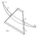
- FIG. 3 is an example of a cross-sectional pictorial view illustrating an optical sample volume intersected by an ultrasound sample volume.
- FIG. 4 depicts a schematic block diagram showing a near infrared spectrophotometer that is suitable for optical sampling and formation of the optical sample volume.
- FIG. 5 is a schematic block diagram showing an acoustic array architecture that is suitable for usage in an optical-acoustic diagnostic apparatus.
- FIGS. 6A and 6B are schematic pictorial diagrams that illustrate examples of a combined optical-acoustic diagnostic apparatus in a catheter oxygenation probe configuration.
- FIG. 7 is a schematic block diagram showing an example of a combined optical-acoustic diagnostic apparatus including processor and display.
- FIG. 8 is a representative pictorial diagram depicting a fetal brain oxygenation test configuration, an example of a clinical application of a combined optical-acoustic diagnostic apparatus.
- FIGS. 9A and 9B are pictorial diagrams that show side and on-axis views of an example of a trans-abdominal fetal tissue calibration phantom or fixture.
- FIGS. 10 and 11 are schematic pictorial diagrams that depict a side view of other examples of a combined optical-acoustic diagnostic apparatus with multiple sets of optical sources and optical detectors.
- FIG. 12 is a schematic pictorial diagram depicts a side view of another example of a combined optical-acoustic diagnostic apparatus having a plurality of optical sources and a plurality of optical detectors with the number of optical sources being different from the number of optical detectors.
- Near infrared spectrophotometry measurements are used in medical, biological, and physiological devices to measure the concentration of light-absorbing analytes in human tissue.
- FIGS. 1A and 1B pictorial diagrams illustrate respective side and top views of an example of a combined optical-acoustic diagnostic apparatus 100 in a trans-abdominal fetal oxygenation probe configuration.
- the illustrative trans-abdominal fetal oxygenation probe 100 includes an optical source 102 and detector 104 , and an ultrasound transducer 106 .
- the optical source 102 and the detector 104 are connected to one or more lateral members 108 or arms that separate the optical source 102 and detector 104 .
- the optical source 102 generates an optical light signal that passes through a medium, for example a tissue sample, interposed between the optical source 102 and detector 104 , and is detected by the detector 104 .
- the optical sample volume is the tissue illuminated by the detected optical light signal.
- the lateral members 108 are rigid arms constructed from any material with suitable mechanical characteristics such as strength, rigidity, weight for supporting and holding the optical source 102 and detector 104 .
- the lateral members 108 are also connected to the ultrasound transducer 106 that generates acoustic signals for transmission as ultrasonic pressure waves into tissue, and receives returning echoes from the tissue.
- the lateral members 108 and the ultrasound transducer 106 connect in a configuration that aligns the optical sample volume to intersect the ultrasound sample volume.
- a bracket 112 couples the ultrasound transducer 106 to the lateral members 108 although any suitable connector can be used.
- position sensors 110 are coupled to the lateral members 108 , for example to facilitate alignment of the optical sample volume and the ultrasound sample volume.
- the position sensors 110 include rotary and linear position sensors that are connected to the ultrasound transducer 106 and the lateral members 108 .
- any suitable optical source 102 can be used.
- the optical source 102 can be formed from semiconductor laser diodes, permitting a relatively low-cost sensor.
- the ultrasound transducer 106 typically includes a plurality of transducer elements arranged in an array, and may be of any suitable transducer type including a linear array, a phased linear array, a phased array, an annular array, or the like.
- FIG. 1B depicts the optical-acoustic diagnostic apparatus 100 in usage for trans-abdominal fetal imaging with the ultrasound transducer 106 , the optical source 102 , and the detector 104 in contact with maternal abdominal skin.
- the ultrasound transducer 106 interrogates a ultrasound sample volume 114 that typically has a trapezoidal shape.
- the optical source 102 and detector 104 generate an optical sample volume 116 .
- the arrangement of the optical source 102 , the detector 104 , and the ultrasound transducer 106 in a same linear plane aligns the optical sample volume 116 to intersect the ultrasound sample volume 114 .
- the position sensors 110 detect the adjustable configuration of the ultrasound transducer 106 , and the lateral members 108 connected to the optical source 102 and the detector 104 , for example at an axle, pin, axis, pivot, or the like for pivotal relative motion of the lateral members 108 .
- Rotary and linear position sensors 110 detect, for example, a source angle 118 and a detector angle 120 .
- the source angle 118 relates to the angle between the ultrasound transducer 106 and the lateral member 108 holding the optical source 102 .
- the detector angle 120 relates to the angle between the ultrasound transducer 106 and the lateral member 108 holding the optical detector 104 .
- the source angle 118 and detector angle 120 can be used using simple geometric relations, for example by a processor, to determine a source-detector distance, based on the known length of the lateral members 108 .
- a suitable processor may be a control circuit, a microprocessor, a microcontroller, a logic circuit, a programmable device logic, or the like.
- an optical-acoustic diagnostic apparatus generally has one or more of several characteristics that promote safety and effectiveness over other diagnostic devices and procedures.
- an optical-acoustic diagnostic apparatus is typically noninvasive and utilizes nonionizing energy.
- the optical-acoustic diagnostic apparatus has a size and form factor that approximate characteristics of a diagnostic ultrasound imager, facilitating bedside utility.
- Typical embodiments can perform continuous tissue oxygenation measurements at rapid refresh rates, for example at rates that meet or exceed a patient's heart rate, a rate that has high clinical utility.
- the optical-acoustic diagnostic apparatus typically has high reliability since fragile fiber optic cables are not required for transmitting and receiving light.
- a three-dimensional pictorial diagram shows tissue fields interrogated by optical and acoustic sensors in an optical-acoustic diagnostic apparatus including an optical sample volume 116 intersected by an ultrasound sample volume 114 .
- the ultrasound sample volume 114 is trapezoid shaped and has a thickness that approximates that of transducer elements in the ultrasound transducer 106 .
- the optical sample volume 116 has a shape that approximates a thickened crescent, “crescent-moon” shape, or banana shape suspended on one end from the optical source 102 and on the other end from the photodetector 104 .
- the optical sample volume 116 may have an approximately symmetric form or may have some asymmetry, depending generally on characteristics of the optical source 102 , the detector 104 , and tissue between the optical source 102 and detector 104 .
- the distance between the optical source 102 and the photodetector 104 determines the depth of the center 202 of the optical sample volume 116 .
- the depth is equal to one-third of the source-detector distance.
- the optical sample volume center 202 moves deeper into tissue in response to lengthening the optical source-photodetector distance.
- Ultrasound imaging can display deep tissue structures but generally does not generate functional information.
- an ultrasound transducer is positioned in contact with a patient's skin and is activated to emit a pulse of acoustic energy into the patient's tissue.
- the optical-acoustic diagnostic apparatus can display echoes from acoustic reflectors in the tissue as a two-dimensional image on a graphics display.
- Near infrared spectrophotometry can be used to obtain diagnostic or functional information from a tissue position identified using ultrasound imaging. Near infrared spectrophotometry involves measurement of tissue adsorption in an optical sample volume. The position of an optical sample volume can be determined by measurement of optical source-detector distance.
- a cross-sectional pictorial view illustrates one example of an optical sample volume 116 intersected by an ultrasound sample volume 114 , approximately in the vicinity of the optical sample volume center 202 .
- the optical sample volume has an approximately circular cross-sectional shape, but may vary in shape according to characteristics of the optical source and detector, and tissue.
- the ultrasound sample volume generally has widening but relatively constant field width in the field near the transducer, with more pronounced widening at further tissue depths.
- the form of the ultrasound sample volume cross-section varies depending focusing characteristics of the ultrasound transducer 106 , the frequency of the ultrasound transducer 106 , and tissue characteristics. Relative sizes of the optical sample volume and the ultrasound sample volume vary depending on the physical dimensions of the optical source 102 and detector 104 , and elements of the ultrasound transducer 106 , and characteristics of the tissue.
- Oxyhemoglobin (HbO 2 ) and deoxyhemoglobin (Hb) concentrations in the optical sample volume 116 are measured by alternately passing narrow band near infrared light of different wavelengths between the optical source 102 and photodetector 104 according to a method of noninvasive optical sensing for measuring near infrared light absorbing analytes described herein.
- a schematic diagram illustrates an example of a near infrared spectrophotometer 400 .
- Fundamental elements of the near infrared spectrophotometer 400 are an optical radiation source 402 and a detector 404 for detecting radiation produced by the optical source 402 .
- the illustrative near infrared spectrophotometer 400 has a single optical source 402 and a single detector 404 although additional sources and detectors may be utilized in other systems.
- the near infrared spectrophotometer 400 also includes a temperature control system 406 including a temperature sensor 408 and a wavelength shifter 410 .
- the near infrared spectrophotometer 400 has control interconnections 412 for controlling the optical source 402 and the temperature control system 406 .
- the control interconnections 412 supply control signals from a controller 414 to the optical source 402 and wavelength shifter 410 , and receive signals from the temperature sensor 408 .
- the controller 414 may be implemented in different forms such as a processor, a CPU, a microcontroller, a digital signal processor (DSP), logic circuits, programmable logic arrays, and the like.
- DSP digital signal processor
- Some examples of the near infrared spectrophotometer 400 may include an internal controller 414 so that the control interconnections 412 may be a control line, a bus, or other internal interconnect.
- Other systems may have an external control system so that the control interconnections 412 may include an interface such as a serial interface, a parallel interface, an external bus interface or the like.
- the controller 414 may include other interconnections for interfacing to external devices, for example infusion pumps, electrophysiologic control devices, ventilators, and many other diagnostic and therapeutic devices.
- the near infrared spectrophotometer 400 may be used in combination with other clinical and laboratory techniques using the interface or without interfacing to improve the diagnosis, treatment, or prevention of a pathophysiologic condition.
- the near infrared spectrophotometer 400 can utilize the controller 414 to monitor physiologic function of a patient.
- the controller 414 can execute processes that monitor physiologic parameters for early recognition of a condition and, upon detection of the condition, rapidly supply a suitable treatment for various conditions.
- monitoring of a condition can be used to control automated administration of drugs to meet the patient's needs.
- Monitoring can be used to automatically reduce automated inspired oxygen levels to minimal levels of effective oxygenation for ventilated patients, reducing problems related to toxicity of excessive concentrations of oxygen.
- the optical source 402 utilizes laser diodes 416 to generate optical radiation.
- the laser diodes 416 are activated by electrical signals from an oscillator 418 as controlled by a multiplexer/modulator 420 .
- Other types of optical sources may be utilized in other embodiments. Suitable optical sources include vertical cavity surface emitting lasers (VCSEL), edge-emitting laser diodes, distributed feedback lasers (DFB), and the like.
- VCSEL vertical cavity surface emitting lasers
- DFB distributed feedback lasers
- a single optical source 402 is used although some systems may utilize multiple optical sources.
- the controller 414 controls the optical radiation source 402 and detector 404 to shift the incident wavelength to reduce or eliminate scattering error.
- the controller 414 controls the multiplexer 420 in the signal pathway from oscillator 418 to the laser diodes 416 to use wavelength shifting on the order of 2-5 nm to reduce scattering error.
- the near infrared spectrophotometer 400 acquires two measurements with an identical optical path. The light loss due to scattering is constant, the same in both measurements, so that a change in reflected light is mainly caused by absorbance of the selected analyte of interest.
- the oscillator 418 generates a 125 MHz signal for both modulation and demodulation.
- Multiplexer 420 sequentially applies radio frequency modulation to each VCSEL in the laser diodes 416 so that only a single VCSEL is activated at any time.
- MEMS micro-electro-mechanical systems
- MOEMS micro-optico-electro-mechanical systems
- a MEMS optical source can be arranged into pixels in which a pixel can be activated by directing a mirror at a projection lens and be deactivated by directing the mirror away from the projection lens.
- measurements can be made at a patient's bedside.
- a clinician places the optical source 402 and photodetector 404 over a body region of the patient at which measurements are desired.
- Near infrared light penetrates several centimeters into the tissue. A portion of the light is reflected back to the photodetector 404 on the skin.
- Wavelengths of the entering light are selected to emphasize the light absorbing compounds of interest.
- High frequency modulation of the light beam is used to determine path length and measure light absorbing compound concentration.
- Slight shifts in wavelength of the optical sources are used to eliminate interference from scattered light.
- the concentration of absorbing analytes in tissue and blood is determined by near infrared spectrophotometry from the difference between the entering light and the reflected light.
- the differences are caused by light absorption in the analytes and the light scattering effect of tissue in the light path including, for example, scalp and skull as well as soft tissue.
- Light absorption is described by an absorption coefficient ⁇ a .
- Light scattering effect is described by a scattering coefficient ⁇ ' s .
- the near infrared spectrophotometer 400 operates at measurement wavelengths at which water does not interfere. Water absorption is weak within the wide 700-900 nm and narrow 1600-1620 nm ranges, allowing clear detection of compounds within the ranges. Light in the wavelength ranges is not absorbed by water and penetrates several centimeters into tissue.
- the near infrared spectrophotometer 400 reduces or eliminates scattering error by varying the entering light wavelength by a few nanometers and then repeating the measurement of the modulation parameters. A slightly different total absorption is obtained because the analyzed absorption coefficients are different for different wavelengths. The scattering coefficient ⁇ ' s , does not change significantly with slight wavelength shift and is therefore a constant.
- ⁇ a 760 ⁇ Hb 760 ⁇ [Hb]+ ⁇ HbO2 760 ⁇ [HbO 2 ] (4)
- BloodFlow ⁇ ⁇ ( m ⁇ ⁇ l blood / min ) O 2 ⁇ ⁇ uptake ⁇ ⁇ ( umol / min ) ( Arterial ⁇ ⁇ O 2 - Venous ⁇ ⁇ O 2 ) ⁇ ⁇ ( umol / mlblood ) . ( 6 )
- k is a constant with units of ml blood /min/ ⁇ mol.
- the near infrared spectrophotometer 400 can measure serum ferritin, typically using controller 414 to perform calculations for solving three equations for absorption coefficients ⁇ a determined at three wavelengths.
- Absorption coefficients ⁇ a are determined at three wavelengths, for example 760 nm to determine deoxyhemoglobin [Hb] concentration, 800 nm to determine oxyhemoglobin [HbO 2 ] concentration and 850 nm to determine ferritin [Fe+ 3 ] concentration.
- Three equations are solved to determine deoxyhemoglobin, oxyhemoglobin, and ferritin concentrations [Hb], [HbO 2 ], and [Fe+ 3 ] concentrations, respectively, in equations (8), (9), and (10), as follows:
- ⁇ a 760 ⁇ Hb 760 ⁇ [Hb]+ ⁇ HbO2 760 ⁇ [HbO 2 ]+ ⁇ Fe+3 760 ⁇ [Fe+ 3 ] (8)
- ⁇ a 800 ⁇ Hb 800 ⁇ [Hb]+ ⁇ HbO2 800 ⁇ [HbO 2 ]+ ⁇ Fe+3 800 ⁇ [Fe+ 3 ] (9)
- ⁇ a 850 ⁇ Hb 850 ⁇ [Hb]+ ⁇ HbO2 850 ⁇ [HbO 2 ]+ ⁇ Fe+2 850 ⁇ [Fe+ 3 ] (10)
- ⁇ hemoglobin and ferritin absorption coefficients that are known physical parameters that are specified at various wavelengths included the measurement wavelengths of 760 nm, 800 nm, and 850 nm.
- the near infrared spectrophotometer 400 can be used to noninvasively measure ferritin with or without iron-binding proteins.
- An additional area of clinical utility of the near infrared spectrophotometer 400 is measurement of parameters such as partial pressure of oxygen (PaO 2 ), partial pressure of carbon dioxide (PaCO 2 ), and pH in tissue.
- the near infrared spectrophotometer 400 is capable of measuring PaCO 2 , PaO 2 , and pH noninvasively, for example by using controller 414 to perform calculations for solving three equations for absorption coefficients ⁇ a determined at three wavelengths.
- Absorption coefficients ⁇ a are determined at three wavelengths, for example 760 nm to determine deoxyhemoglobin [Hb] concentration, 800 nm to determine oxyhemoglobin [HbO 2 ] concentration, and 1620 nm to determine carbon dioxide [CO 2 ] concentration.
- Three equations are solved to determine deoxyhemoglobin, oxyhemoglobin, and carbon dioxide concentrations [Hb], [HbO 2 ], and [CO 2 ] concentrations, respectively, in equations (11), (12), and (13
- ⁇ a 760 ⁇ Hb 760 ⁇ [Hb]+ ⁇ HbO2 760 ⁇ [HbO 2 ]+ ⁇ CO2 760 ⁇ [CO 2 ] (11)
- ⁇ a 800 ⁇ Hb 800 ⁇ [Hb]+ ⁇ HbO2 800 ⁇ [HbO 2 ]+ ⁇ CO2 800 ⁇ [CO 2 ] (12)
- ⁇ a 1620 ⁇ Hb 1620 ⁇ [Hb]+ ⁇ HbO2 1620 ⁇ [HbO 2 ]+ ⁇ CO2 1620 ⁇ [CO 2 ] (13)
- ⁇ hemoglobin and carbon dioxide absorption coefficients that are known physical parameters that are specified at various wavelengths included the measurement wavelengths of 760 nm, 800 nm, and 1620 nm.
- a schematic block diagram shows an acoustic array architecture 500 that is suitable for usage in an optical-acoustic diagnostic apparatus 100 .
- One illustrative ultrasound transducer 106 is a linear ultrasound array 502 with multiple ultrasound transducer elements 504 .
- the ultrasound transducer elements 504 are mounted on an ultrasound transducer support 506 .
- the linear ultrasound array 502 has a plurality of ultrasound transducer elements 504 , typically in the form of piezoelectric (PZT) wideband crystals.
- the ultrasound transducer elements 504 extend through the ultrasound transducer support 506 and extend to a body interface surface 508 so that ultrasound transducer elements 504 transmit ultrasound waves outward from the body interface surface 508 into tissue.
- the ultrasound transducer elements 504 are arranged in a linear matrix that produces a field of view by multiple acoustic lines propagated normal to the face of the linear ultrasound array 502 .
- a delay circuit 512 generates extensions of the normal acoustic lines pass through a common center of curvature 510 .
- the linear ultrasound array 502 can be configured in a planar form, curved form, or other suitable form to produce a desired ultrasound sample volume.
- the field of view for a curved linear transducer array can be expanded by a set of acoustic lines propagated at varying angles to the face of the curved linear array.
- Various shapes, forms, and configurations of linear arrays are well known in the art of ultrasound imaging.
- Various ultrasound focusing techniques are well known for suitably forming a ultrasound sample volume.
- ultrasound transducer 106 configurations include two-dimensional arrays of various forms including matrices of circular, square, oval, or other shape.
- Annular ultrasound transducer arrays may be utilized.
- the various shapes, forms, and configurations of two-dimensional ultrasound arrays, and associated beam-forming techniques are well-known and may be implemented in various embodiments of the optical-acoustic diagnostic apparatus 100 .
- a schematic pictorial diagram illustrates an example of a combined optical-acoustic diagnostic apparatus 600 , which may also be called a probe, in a catheter oxygenation probe configuration.
- Combined optical-acoustic diagnostic apparatus 600 is an example of a near infrared spectrophotometer (NIRS) that is useful for tissue oxygenation monitoring.
- NIRS near infrared spectrophotometer
- the ultrasound guided optical-acoustic diagnostic apparatus 600 has a fixture 601 that holds an optical source 602 , an optical detector 604 , and an ultrasound transducer 606 in a single plane.
- the optical source 602 , the optical detector 604 , and the ultrasound transducer 606 are distributed in a line with the ultrasound transducer 606 between the optical source 602 and the optical detector 604 .
- the optical source 602 and optical detector 604 generate an optical sample volume 616 that intersects an ultrasound sample volume 614 formed by the ultrasound transducer 606 .
- the ultrasound sample volume 614 is typically interrogated by ultrasound imaging to produce a multi-dimensional ultrasound image.
- the optical sample volume 616 depicts diagnostic characteristics of tissue in a pathway between the optical source 602 and detector 604 that can be positioned within the ultrasound image.
- the ultrasound guided NIRS system is capable of monitoring fetal oxygenation and fetal heart rate during labor and delivery.
- a typical ultrasound guided NIRS embodiment is substantially noninvasive, utilizes nonionizing energy, and can be used at the bedside because the size and form factor are the same as a diagnostic ultrasound imager.
- the ultrasound guided NIRS can provide continuous tissue oxygenation measurements at the same rate as the heart rate.
- Ultrasound guided NIRS can have low cost because of utilization of semiconductor laser diodes for the optical source. Ultrasound guided NIRS does not require fragile fiber optic cables to transmit and receive the light and thus is highly reliable.
- the fixture 601 comprises three concentrically-arranged catheters, for example arranged in a telescopic configuration.
- an optical source catheter 620 is connected to the optical source 602 and is enclosed within a larger ultrasound transducer catheter 622 .
- the ultrasound transducer catheter 622 is connected to the ultrasound transducer 606 and is enclosed within a larger optical detector catheter 624 .
- the optical source catheter 620 extends from the ultrasound transducer catheter 622 that extends from the optical detector catheter 624 .
- the fixture 601 can be arranged so that the optical source 602 and the optical detector 604 are interchanged.
- the catheter optical-acoustic diagnostic apparatus 600 may further comprise an inflatable balloon 626 that, when inflated, holds the fixture 601 against an organ wall 650 to enable diagnostic measurements of different tissues 652 .
- the optical-acoustic diagnostic apparatus 600 is a probe that can be inserted into a cavity or vessel, such as the esophagus, artery, vein, rectum, nasal passages and the like, and held against the organ wall 650 with the inflatable balloon 626 .
- the optical source catheter 620 , the ultrasound transducer catheter 622 , and the optical detector catheter 624 can be extended or retracted mutually independently allowing for a variable source-photodetector distance and variable centering of the ultrasound transducer 606 .
- a position detector (not shown) detects relative positioning of the catheter.
- the catheter optical-acoustic diagnostic apparatus 600 can be used for many functions. In one example, the catheter optical-acoustic diagnostic apparatus 600 can be used for determining myocardial oxygenation in heart monitoring.
- a clinician can rotate, extend, or retract the ultrasound transducer array catheter 622 to position the ultrasound sample volume 614 in a selected tissue field in the myocardium.
- the clinician can extend or retract either or both the optical source catheter 620 and optical detector catheter 624 to position the optical sample volume outline through the myocardium on an electronic display.
- the clinician can inflate the inflatable balloon 626 to hold the optical-acoustic probe 600 in position.
- the clinician can activate the optical-acoustic probe 600 to continuously measure tissue oxygenation using near infrared spectrometry (NIRS).
- NIRS near infrared spectrometry
- the catheter optical-acoustic diagnostic apparatus 600 may be used for intrauterine fetal monitoring and include an annunciator (not shown) and trigger (not shown) that operate in combination to generate an annunciator signal when the tissue oxygenation level has reached a threshold. A clinician can respond to the annunciator signal by beginning appropriate procedures.
- FIG. 6B a schematic pictorial diagram illustrates an alternative embodiment of a combined optical-acoustic diagnostic apparatus 660 in a catheter oxygenation probe configuration, a catheter near infrared spectrophotometer (NIRS) that is useful for myocardium oxygenation monitoring.
- the catheter optical-acoustic diagnostic apparatus 660 has a catheter 665 that holds an optical source 662 , an optical detector 664 , and an ultrasound transducer 670 in a single plane. In that single plane, the optical source 662 , the optical detector 664 , and the ultrasound transducer 670 are distributed in a line with the ultrasound transducer 670 between the optical source 662 and the optical detector 664 .
- the optical source 662 and optical detector 664 generate an optical sample volume 676 that intersects an ultrasound sample volume 674 formed by the ultrasound transducer 670 .
- the ultrasound sample volume 674 is typically interrogated by ultrasound imaging to produce a multi-dimensional ultrasound image.
- the optical sample volume 676 depicts diagnostic characteristics of tissue in a pathway between the optical source 662 and detector 664 that can be positioned within the ultrasound image.
- the catheter 665 contains any signal conductive elements for driving signals to the optical source 662 and elements of the ultrasound transducer 670 and sensing signals received from the ultrasound transducer elements and the optical detector 664 .
- Typical signal conductive elements may be optical or electric transmission lines.
- the catheter 665 can be arranged so that the optical source 662 , the optical detector 664 , and the ultrasound transducer elements are in any suitable order.
- the catheter optical-acoustic diagnostic apparatus 660 may further comprise an inflatable balloon 672 that, when inflated, holds the catheter 665 against an organ or tissue wall 670 to enable diagnostic measurements within the tissue 690 .
- the catheter optical-acoustic diagnostic apparatus 660 is a probe that can be inserted into a patient's esophagus and held against the esophageal wall 670 with the inflatable balloon 672 .
- the source-photodetector distance and centering of the ultrasound transducer 670 are fixed in the illustrative catheter 665 .
- a schematic block diagram shows an example of a combined optical-acoustic diagnostic apparatus 700 including processor 702 and electronic display 704 .
- the processor 702 can be any type of general-purpose or special-purpose processor or computer such as a microprocessor, microcontroller, central processing unit, programmable control logic, state machine, or the like.
- the electronic display 704 is any suitable general-purpose or special-purpose display device, such as an electronic graphics display.
- the optical-acoustic diagnostic apparatus 700 also includes an optical-acoustic imaging probe 706 .
- the optical-acoustic imaging probe 706 include the trans-abdominal fetal oxygenation probe 100 , the catheter optical-acoustic diagnostic apparatus 600 , or other optical-acoustic device that includes an optical source and detector, and an ultrasound transducer, as described hereinbefore.
- the electronic display 704 can present a two-dimensional ultrasound image of the structure of imaged anatomy.
- the processor 702 can calculate a theoretical optical sample volume based on source-photodetector distance and optical properties of patient tissues 708 in the optical sample volume.
- the processor 702 superimposes a portion of the optical sample volume that intersects the ultrasound sample volume over the ultrasound image.
- the optical sample volume outline can be represented by either dotted lines or shading.
- a clinician may first manipulate the ultrasound transducer so the ultrasound image passes through target tissue for performing an oxygenation measurement.
- the clinician either may increase or decrease the optical source-photodetector distance to position the optical sample volume outline through the tissue of interest. Increasing the source-photodetector distance results in a deeper optical sample volume outline. Decreasing the source-photodetector distance results in a shallower optical sample volume outline.
- the clinician then initiates a near infrared spectrometry (NIRS) oxygenation measurement of the tissue of interest.
- NIRS near infrared spectrometry
- a representative pictorial diagram depicts an example of a fetal brain oxygenation test configuration 800 including an optical-acoustic probe 802 held by a stereotaxic holder 804 .
- the optical-acoustic probe 802 includes an optical source 806 , optical photodetector 808 , and ultrasound transducer 810 .
- a cable 812 connects the optical-acoustic probe 802 to an imaging system.
- a clinician places the trans-abdominal fetal oxygenation probe 802 in contact with a patient's skin 814 in the vicinity of the mother's abdomen.
- the clinician manipulates the trans-abdominal oxygenation probe 802 to position the ultrasound sample volume 816 through the center of the fetal skull 818 by viewing an ultrasound image acquired by usage of the ultrasound transducer 810 on an electronic display.
- the clinician increases or decreases the optical source-photodetector distance to position the optical sample volume outline through the center of the fetal skull on the electronic display.
- the clinician can acquire a measurement of hemoglobin (Hb) and oxyhemoglobin (HbO2) is taken with near infrared spectrometry (NIRS).
- Hb hemoglobin
- HbO2 oxyhemoglobin
- the optical-acoustic probe 802 can be used to image any deep tissue, organs, a fetus in a maternal condition, and the like.
- Biological tissue varies in index of refraction and optical properties among different tissues in one person and among different individual persons. The shape and position of an optical sample volume varies based on the refraction index and optical properties so that calibration is generally useful to produce accurate measurements.
- “Phantoms” are test fixtures composed materials with the optical properties that are equivalent or approximately equivalent to trans-abdominal, trans-esophageal, or other desired target tissues. Phantoms typically mimic oxygenation characteristics of actual biological tissue. The tissue phantoms can be used to determine the shape and position of the optical sample volume for a specific source-photodetector distance.
- FIGS. 9A and 9B pictorial diagrams show side and on-axis views of an example of a trans-abdominal fetal tissue calibration phantom or fixture 900 .
- the illustrative trans-abdominal fetal tissue calibration phantom 900 has a spherical shape although other shapes including oval, oblong, cylindrical, or other shapes may be used.
- the illustrative trans-abdominal fetal tissue calibration phantom 900 has two regions containing material with different absorption characteristics, although other phantoms may include more or fewer regions.
- the illustrative trans-abdominal fetal tissue calibration phantom 900 includes an inner vesicle 902 containing a low absorptive material and an outer region 904 containing a high absorptive material.
- the low absorptive material and the high absorptive material approximate characteristics of biological tissue.
- the trans-abdominal fetal tissue calibration phantom 900 includes the inner vesicle 902 that approximates characteristics of the fetal brain sphere.
- the trans-abdominal fetal tissue calibration phantom 900 includes the outer region 904 that approximates characteristics of the abdominal wall and the amniotic fluid.
- a centerline 906 of the inner vesicle cylinder 902 is parallel to the optical path of the photons at the deepest point of the sample volume.
- the optical-acoustic diagnostic apparatus is calibrated by determining the source-photodetector distance where the optical sample volume is positioned in the low absorption cylinder of the brain sphere.
- the source-photodetector distance that results in the optical sample volume being positioned in the low absorptive cylinder of the brain sphere is experimentally determined.
- the calibration procedure begins with a very short source-photodetector distance.
- the photodetector signal is low as the beam passes completely through the abdominal wall layer and increases through the amniotic fluid layer.
- the photodetector signal then decreases as the beam passes through the high absorptive section of the fetal brain sphere and increases as the beam continues through the low absorptive center cylinder of the fetal brain sphere.
- the photodetector signal decreases as the beam passes through the deeper high absorptive section of the fetal brain sphere.
- a pictorial diagram illustrates an example of a trans-esophageal myocardium tissue phantom 1000 .
- the illustrative trans-esophageal myocardium tissue phantom 1000 includes a plurality of layers of material having predetermine optical absorption characteristics.
- the layers are in the form of rectangular blocks of like length and width, and selected thickness', which are typically variable to simulate the thickness of various biological tissues.
- the geometry and structure of the layers may be selected to suitably match a particular tissue for a desired application. For example, the sizes may differ for embodiments that simulate tissue other than trans-esophageal myocardium.
- the illustrative trans-esophageal myocardium tissue phantom 1000 has an esophageal wall layer 1002 on an outer surface 1004 , an outer heart layer 1006 coupled to the esophageal wall layer 1002 , and a myocardium layer 1008 coupled to the outer heart layer 1006 .
- An inner heart wall layer 1010 is coupled to the myocardium layer 1008 .
- a heart chamber layer 1012 may be coupled to the inner heart wall layer 1010 .
- the esophageal wall layer 1002 is 2 mm thick and has a medium absorption characteristic.
- the outer heart layer 1006 is 1 mm thick and also has a medium absorption characteristic that is typically different from the absorption characteristic of the esophageal wall layer 1002 .
- the myocardium layer 1008 is 1 to 2 cm thick and typically has a low absorption characteristic.
- the inner heart wall layer 1010 is 1 cm thick and has a high absorption characteristic.
- a typical low absorption characteristic has a range from 0 to 0.006 mm ⁇ 1 .
- a typical medium absorption characteristic has a range from 0.006 to 0.016 mm ⁇ .
- a typical high absorption characteristic has a range from 0.016 to a maximum of approximately 0.04 mm ⁇ 1 .
- a source-photodetector distance that positions the optical sample volume in the center of the myocardium layer is experimentally determined. For a short source-photodetector distance, the optical sample volume only passes through the medium absorption of the esophageal wall 1002 and outer wall of the heart 1006 . As the source-photodetector distance increases, absorption decreases because the absorption of photons is increased due to the longer path length. The source-photodetector distance is increased until the increase in absorbance of the inner wall 1010 is detected. The ratio of source-photodetector distance to myocardium depth is computed and used to display the optical sample volume outline.
- a schematic pictorial diagram depicts a side view of another example of a combined optical-acoustic diagnostic apparatus 1100 having multiple sets of optical source-detectors 1130 , 1132 , and 1134 , and an ultrasound transducer 1106 .
- the multiple optical source-detectors 1130 , 1132 , and 1132 of the illustrative optical-acoustic diagnostic apparatus 1100 each include a plurality of optical sources 1102 and detector 1104 .
- the multiple optical source-detectors 1130 , 1132 , and 1132 are connected to lateral members 1108 or arms that separate the respective optical sources 1102 and detectors 1104 .
- the optical source-detectors 1130 , 1132 , and 1132 each generate separate optical sample volumes that are positioned in different portions of tissue, and that intersect the ultrasound sample volume.
- the illustrative optical-acoustic diagnostic apparatus 1100 includes three sets of optical source-detectors 1130 , 1132 , and 1132 , any suitable number may be utilized so long as the optical sources 1102 , optical detectors 1104 , and ultrasound transducer 1106 are in the same plane so that all optical sample volumes intersect the ultrasound sample volume. In other embodiments, multiple ultrasound transducers may be used.
- Additional volumes may be imaged as shown in FIG. 11 by detecting light emitted from various sources.
- dashed lines show the optical volume 1140 generated by source 1134 and detector 1130 .
- any of the detectors sense light emitted by any of the sources.
- Different optical samples can be generated, for example simply by correlating the timing of emission by the different sources and the detection by the different detectors.
- a schematic pictorial diagram depicts a side view of another example of a combined optical-acoustic diagnostic apparatus 1200 having a plurality of optical sources 1202 and a plurality of optical detectors 1204 with the number of optical sources 1202 being different from the number of optical detectors 1204 .
- the multiple optical sources 1202 and optical detectors 1204 are connected to lateral members 1208 or arms that separate the respective optical sources 1202 and detectors 1204 .
- the optical sources 1202 and optical detectors 1204 generate separate optical sample volumes that are positioned in different portions of tissue, and that intersect the ultrasound sample volume.
- the illustrative optical-acoustic diagnostic apparatus 1200 includes a single optical source 1202 and three optical detectors 1204 , any suitable number may be utilized so long as the optical sources 1202 , optical detectors 1204 , and ultrasound transducer 1206 are in the same plane so that all optical sample volumes intersect the ultrasound sample volume. In other embodiments, multiple ultrasound transducers may be used.
Abstract
Description


Claims (25)
Priority Applications (1)
| Application Number | Priority Date | Filing Date | Title |
|---|---|---|---|
| US10/143,248 US6690958B1 (en) | 2002-05-07 | 2002-05-07 | Ultrasound-guided near infrared spectrophotometer |
Applications Claiming Priority (1)
| Application Number | Priority Date | Filing Date | Title |
|---|---|---|---|
| US10/143,248 US6690958B1 (en) | 2002-05-07 | 2002-05-07 | Ultrasound-guided near infrared spectrophotometer |
Publications (1)
| Publication Number | Publication Date |
|---|---|
| US6690958B1 true US6690958B1 (en) | 2004-02-10 |
Family
ID=30769159
Family Applications (1)
| Application Number | Title | Priority Date | Filing Date |
|---|---|---|---|
| US10/143,248 Expired - Fee Related US6690958B1 (en) | 2002-05-07 | 2002-05-07 | Ultrasound-guided near infrared spectrophotometer |
Country Status (1)
| Country | Link |
|---|---|
| US (1) | US6690958B1 (en) |
Cited By (178)
| Publication number | Priority date | Publication date | Assignee | Title |
|---|---|---|---|---|
| US20010056238A1 (en) * | 2000-06-26 | 2001-12-27 | Fuji Photo Film Co., Ltd. | Fluorescent image obtaining apparatus |
| US20030225320A1 (en) * | 2002-03-20 | 2003-12-04 | Jeon Kye-Jin | Apparatus and method for non-invasively measuring bio-fluid concentrations using photoacoustic spectroscopy |
| US20040064022A1 (en) * | 2002-09-27 | 2004-04-01 | Infraredx, Inc. | Spectroscopic catheter system with widely tunable source and method of operation |
| US20040215072A1 (en) * | 2003-01-24 | 2004-10-28 | Quing Zhu | Method of medical imaging using combined near infrared diffusive light and ultrasound |
| US20040260182A1 (en) * | 2003-06-23 | 2004-12-23 | Zuluaga Andres F. | Intraluminal spectroscope with wall contacting probe |
| US20040267139A1 (en) * | 2001-11-09 | 2004-12-30 | Naohiro Kanayama | Instrument for measuring intrauterine oxygen metabolism using optical technique |
| US20050054908A1 (en) * | 2003-03-07 | 2005-03-10 | Blank Thomas B. | Photostimulation method and apparatus in combination with glucose determination |
| US20050075574A1 (en) * | 2003-09-22 | 2005-04-07 | Simon Furnish | Devices for vulnerable plaque detection |
| US20050154286A1 (en) * | 2004-01-02 | 2005-07-14 | Neason Curtis G. | System and method for receiving and displaying information pertaining to a patient |
| US20050159656A1 (en) * | 2003-03-07 | 2005-07-21 | Hockersmith Linda J. | Method and apparatus for presentation of noninvasive glucose concentration information |
| US20050187439A1 (en) * | 2003-03-07 | 2005-08-25 | Blank Thomas B. | Sampling interface system for in-vivo estimation of tissue analyte concentration |
| US20050197579A1 (en) * | 2004-03-08 | 2005-09-08 | Nellcor Puritan Bennett Incorporated | Method and apparatus for optical detection of mixed venous and arterial blood pulsation in tissue |
| US20050203359A1 (en) * | 2000-05-02 | 2005-09-15 | Blank Thomas B. | Optical sampling interface system for in-vivo measurement of tissue |
| US20050267342A1 (en) * | 2004-04-28 | 2005-12-01 | Blank Thomas B | Noninvasive analyzer sample probe interface method and apparatus |
| US20060116562A1 (en) * | 2002-03-08 | 2006-06-01 | Acosta George M | Compact apparatus for noninvasive measurement of glucose through near-infrared spectroscopy |
| US20060116560A1 (en) * | 2004-11-30 | 2006-06-01 | Lms Medical Systems Ltd. | Method and apparatus for estimating a likelihood of shoulder dystocia |
| US20060116559A1 (en) * | 2004-11-30 | 2006-06-01 | Lms Medical Systems Ltd. | Method and apparatus for estimating a likelihood of shoulder dystocia |
| US20060122514A1 (en) * | 2004-11-23 | 2006-06-08 | Ep Medsystems, Inc. | Method and apparatus for localizing an ultrasound catheter |
| US20060135860A1 (en) * | 2003-01-10 | 2006-06-22 | Baker Clark R Jr | Signal quality metrics design for qualifying data for a physiological monitor |
| US20060184037A1 (en) * | 2004-11-30 | 2006-08-17 | Can Ince | Pulsed lighting imaging systems and methods |
| US20060195041A1 (en) * | 2002-05-17 | 2006-08-31 | Lynn Lawrence A | Centralized hospital monitoring system for automatically detecting upper airway instability and for preventing and aborting adverse drug reactions |
| US20060200017A1 (en) * | 2002-03-08 | 2006-09-07 | Monfre Stephen L | Noninvasive targeting system method and apparatus |
| US20060206018A1 (en) * | 2005-03-04 | 2006-09-14 | Alan Abul-Haj | Method and apparatus for noninvasive targeting |
| US20060211931A1 (en) * | 2000-05-02 | 2006-09-21 | Blank Thomas B | Noninvasive analyzer sample probe interface method and apparatus |
| US20060224053A1 (en) * | 2005-03-30 | 2006-10-05 | Skyline Biomedical, Inc. | Apparatus and method for non-invasive and minimally-invasive sensing of venous oxygen saturation and pH levels |
| US20060241364A1 (en) * | 2004-10-01 | 2006-10-26 | Academisch Medisch Centrum Of The University Van Amsterdam | System and method for imaging the reflectance of a substrate |
| US20060247536A1 (en) * | 2003-08-21 | 2006-11-02 | Mcgill University | Method and apparatus for analyzing amniotic fluid |
| US20060253007A1 (en) * | 2005-03-30 | 2006-11-09 | Skyline Biomedical, Inc. | Apparatus and method for non-invasive and minimally-invasive sensing of parameters relating to blood |
| US20060264720A1 (en) * | 2004-02-25 | 2006-11-23 | Nellcor Puritan Bennett Incorporated A Corporation Of Delaware | Switch-mode oximeter LED drive with a single inductor |
| US20060264717A1 (en) * | 2003-01-13 | 2006-11-23 | Benny Pesach | Photoacoustic assay method and apparatus |
| US20060276712A1 (en) * | 2003-10-15 | 2006-12-07 | Lynn Stothers | Methods and apparatus for urodynamic analysis |
| US20060281992A1 (en) * | 2003-10-15 | 2006-12-14 | Lynn Stothers | Bladder function monitoring methods, apparatuses, media and signals |
| US20070032714A1 (en) * | 2001-07-19 | 2007-02-08 | Nellcor Puritan Bennett Inc. | Nuisance alarm reductions in a physiological monitor |
| US20070073124A1 (en) * | 2005-09-29 | 2007-03-29 | Li Li | System and method for removing artifacts from waveforms |
| US20070076212A1 (en) * | 2005-09-30 | 2007-04-05 | Zuluaga Andres F | Detecting vulnerable plaque |
| US20070093721A1 (en) * | 2001-05-17 | 2007-04-26 | Lynn Lawrence A | Microprocessor system for the analysis of physiologic and financial datasets |
| US20070093702A1 (en) * | 2005-10-26 | 2007-04-26 | Skyline Biomedical, Inc. | Apparatus and method for non-invasive and minimally-invasive sensing of parameters relating to blood |
| US20070106137A1 (en) * | 2004-03-09 | 2007-05-10 | Baker Clark R Jr | Pulse oximetry signal correction using near infrared absorption by water |
| US20070129647A1 (en) * | 2000-07-28 | 2007-06-07 | Lynn Lawrence A | System and method for CO2 and oximetry integration |
| US20070149868A1 (en) * | 2002-03-08 | 2007-06-28 | Blank Thomas B | Method and Apparatus for Photostimulation Enhanced Analyte Property Estimation |
| US20070160973A1 (en) * | 2006-01-09 | 2007-07-12 | Mcgill University | Method to determine state of a cell exchanging metabolites with a fluid medium by analyzing the metabolites in the fluid medium |
| US20070208259A1 (en) * | 2006-03-06 | 2007-09-06 | Mannheimer Paul D | Patient monitoring alarm escalation system and method |
| US20070232874A1 (en) * | 2003-10-03 | 2007-10-04 | Can Ince | System and method for imaging the reflectance of a substrate |
| US20070234300A1 (en) * | 2003-09-18 | 2007-10-04 | Leake David W | Method and Apparatus for Performing State-Table Driven Regression Testing |
| US20070238953A1 (en) * | 2004-06-17 | 2007-10-11 | Koninklijke Philips Electronics, N.V. | Combined ultrasonic imaging and spectroscopic molecular analysis |
| US20070299329A1 (en) * | 2006-06-22 | 2007-12-27 | Jonas Alexander Pologe | Spring wing assembly for photoplethysmorgraphic sensor |
| US20080004513A1 (en) * | 2006-06-30 | 2008-01-03 | Walker Stephen D | VCSEL Tissue Spectrometer |
| US20080033275A1 (en) * | 2004-04-28 | 2008-02-07 | Blank Thomas B | Method and Apparatus for Sample Probe Movement Control |
| US20080058638A1 (en) * | 2006-07-06 | 2008-03-06 | Quing Zhu | Method and apparatus for medical imaging using near-infrared optical tomography and flourescence tomography combined with ultrasound |
| US20080076986A1 (en) * | 2006-09-20 | 2008-03-27 | Nellcor Puritan Bennett Inc. | System and method for probability based determination of estimated oxygen saturation |
| US20080076977A1 (en) * | 2006-09-26 | 2008-03-27 | Nellcor Puritan Bennett Inc. | Patient monitoring device snapshot feature system and method |
| US20080082338A1 (en) * | 2006-09-29 | 2008-04-03 | O'neil Michael P | Systems and methods for secure voice identification and medical device interface |
| US20080081970A1 (en) * | 2006-09-29 | 2008-04-03 | Nellcor Puritan Bennett Incorporated | Pulse oximetry sensor switchover |
| US20080082009A1 (en) * | 2006-09-28 | 2008-04-03 | Nellcor Puritan Bennett Inc. | System and method for pulse rate calculation using a scheme for alternate weighting |
| US20080082339A1 (en) * | 2006-09-29 | 2008-04-03 | Nellcor Puritan Bennett Incorporated | System and method for secure voice identification in a medical device |
| US20080081974A1 (en) * | 2006-09-29 | 2008-04-03 | Nellcor Puritan Bennett Incorporated | Pathological condition detector using kernel methods and oximeters |
| US20080081956A1 (en) * | 2006-09-29 | 2008-04-03 | Jayesh Shah | System and method for integrating voice with a medical device |
| US20080097175A1 (en) * | 2006-09-29 | 2008-04-24 | Boyce Robin S | System and method for display control of patient monitor |
| US20080114211A1 (en) * | 2006-09-29 | 2008-05-15 | Edward Karst | System and method for assuring validity of monitoring parameter in combination with a therapeutic device |
| US20080114226A1 (en) * | 2006-09-29 | 2008-05-15 | Doug Music | Systems and methods for user interface and identification in a medical device |
| US20080177183A1 (en) * | 2007-01-19 | 2008-07-24 | Brian Courtney | Imaging probe with combined ultrasounds and optical means of imaging |
| US20080189783A1 (en) * | 2006-09-29 | 2008-08-07 | Doug Music | User interface and identification in a medical device system and method |
| US20080200819A1 (en) * | 2007-02-20 | 2008-08-21 | Lynn Lawrence A | Orthostasis detection system and method |
| US20080200775A1 (en) * | 2007-02-20 | 2008-08-21 | Lynn Lawrence A | Maneuver-based plethysmographic pulse variation detection system and method |
| US20080214906A1 (en) * | 2006-03-21 | 2008-09-04 | Nellcor Puritan Bennett Llc | Patient Monitoring Help Video System and Method |
| US20080221426A1 (en) * | 2007-03-09 | 2008-09-11 | Nellcor Puritan Bennett Llc | Methods and apparatus for detecting misapplied optical sensors |
| US20080255436A1 (en) * | 2005-03-03 | 2008-10-16 | Nellcor Puritain Bennett Incorporated | Method for Enhancing Pulse Oximery Calculations in the Presence of Correlated Artifacts |
| US20080312533A1 (en) * | 2005-03-16 | 2008-12-18 | Or-Nim Medical Ltd. | Noninvasive Measurements in a Human Body |
| US20080319299A1 (en) * | 2004-04-28 | 2008-12-25 | Stippick Timothy W | Method and apparatus for controlling positioning of a noninvasive analyzer sample probe |
| US20080319382A1 (en) * | 2002-03-08 | 2008-12-25 | Blank Thomas B | Method and apparatus for coupling a channeled sample probe to tissue |
| US20090005662A1 (en) * | 2004-02-25 | 2009-01-01 | Nellcor Puritan Bennett Inc | Oximeter Ambient Light Cancellation |
| US20090069674A1 (en) * | 2007-09-12 | 2009-03-12 | Canon Kabushiki Kaisha | Measurement apparatus |
| US20090080007A1 (en) * | 2007-09-25 | 2009-03-26 | Brother Kogyo Kabushiki Kaisha | Printing device and method therefor |
| US20090082651A1 (en) * | 2004-03-08 | 2009-03-26 | Nellcor Puritan Bennett Llc | Selection of ensemble averaging weights for a pulse oximeter based on signal quality metrics |
| US7515948B1 (en) | 2003-09-12 | 2009-04-07 | Ornim Inc. | Photoacoustic analyzer of region of interest in a human body |
| US20090154573A1 (en) * | 2007-12-13 | 2009-06-18 | Nellcor Puritan Bennett Llc | Signal Demodulation |
| US20090171167A1 (en) * | 2007-12-27 | 2009-07-02 | Nellcor Puritan Bennett Llc | System And Method For Monitor Alarm Management |
| US20090171174A1 (en) * | 2007-12-31 | 2009-07-02 | Nellcor Puritan Bennett Llc | System and method for maintaining battery life |
| US20090171226A1 (en) * | 2007-12-31 | 2009-07-02 | Nellcor Puritan Bennett Llc | System and method for evaluating variation in the timing of physiological events |
| US20090171172A1 (en) * | 2008-12-19 | 2009-07-02 | Nellcor Puritan Bennett Llc | Method and system for pulse gating |
| US20090171205A1 (en) * | 2006-01-03 | 2009-07-02 | Koninklijke Philips Electronics N.V. | Method and system for locating blood vessels |
| US20090209839A1 (en) * | 2008-02-19 | 2009-08-20 | Nellcor Puritan Bennett Llc | Methods And Systems For Alerting Practitioners To Physiological Conditions |
| US20090210163A1 (en) * | 2008-02-19 | 2009-08-20 | Nellcor Puritan Bennett Llc | System And Method For Evaluating Physiological Parameter Data |
| US20090221889A1 (en) * | 2004-03-08 | 2009-09-03 | Nellcor Puritan Bennett Llc | Pulse Oximeter With Alternate Heart-Rate Determination |
| US20090247852A1 (en) * | 2008-03-31 | 2009-10-01 | Nellcor Puritan Bennett Llc | System and method for facilitating sensor and monitor communication |
| US20090247851A1 (en) * | 2008-03-26 | 2009-10-01 | Nellcor Puritan Bennett Llc | Graphical User Interface For Monitor Alarm Management |
| US20090247850A1 (en) * | 2008-03-28 | 2009-10-01 | Nellcor Puritan Bennett Llc | Manually Powered Oximeter |
| US20090248320A1 (en) * | 2008-03-27 | 2009-10-01 | Nellcor Puritan Benett Llc | System And Method For Unmixing Spectroscopic Observations With Nonnegative Matrix Factorization |
| US20090247840A1 (en) * | 2002-03-08 | 2009-10-01 | Sensys Medical, Inc. | Method and apparatus for coupling a sample probe with a sample site |
| WO2009124242A1 (en) * | 2008-04-03 | 2009-10-08 | Infraredx, Inc. | System and method for intravascular structural analysis compensation of chemical analysis modality |
| US20090253971A1 (en) * | 2005-10-28 | 2009-10-08 | Nellcor Puritan Bennett Llc | Adjusting parameters used in pulse oximetry analysis |
| US20090264768A1 (en) * | 2007-01-19 | 2009-10-22 | Brian Courtney | Scanning mechanisms for imaging probe |
| US20090281838A1 (en) * | 2008-05-07 | 2009-11-12 | Lawrence A. Lynn | Medical failure pattern search engine |
| US20090326335A1 (en) * | 2008-06-30 | 2009-12-31 | Baker Clark R | Pulse Oximeter With Wait-Time Indication |
| US20090327515A1 (en) * | 2008-06-30 | 2009-12-31 | Thomas Price | Medical Monitor With Network Connectivity |
| US20100000330A1 (en) * | 2008-07-06 | 2010-01-07 | Or-Nim Medical Ltd. | Method and system for non-invasively monitoring fluid flow in a subject |
| US20100049099A1 (en) * | 2008-07-18 | 2010-02-25 | Vytronus, Inc. | Method and system for positioning an energy source |
| US20100081899A1 (en) * | 2008-09-30 | 2010-04-01 | Nellcor Puritan Bennett Llc | System and Method for Photon Density Wave Pulse Oximetry and Pulse Hemometry |
| US20100081890A1 (en) * | 2008-09-30 | 2010-04-01 | Nellcor Puritan Bennett Llc | System And Method For Enabling A Research Mode On Physiological Monitors |
| US20100081897A1 (en) * | 2008-09-30 | 2010-04-01 | Nellcor Puritan Bennett Llc | Transmission Mode Photon Density Wave System And Method |
| US20100079292A1 (en) * | 1997-01-27 | 2010-04-01 | Lawrence A. Lynn | Microprocessor system for the analysis of physiologic and financial datasets |
| US20100094134A1 (en) * | 2008-10-14 | 2010-04-15 | The University Of Connecticut | Method and apparatus for medical imaging using near-infrared optical tomography combined with photoacoustic and ultrasound guidance |
| US20100113909A1 (en) * | 2008-10-31 | 2010-05-06 | Nellcor Puritan Bennett Llc | System And Method For Facilitating Observation Of Monitored Physiologic Data |
| US20100113908A1 (en) * | 2008-10-31 | 2010-05-06 | Nellcor Puritan Bennett Llc | System And Method For Facilitating Observation Of Monitored Physiologic Data |
| US7720516B2 (en) | 1996-10-10 | 2010-05-18 | Nellcor Puritan Bennett Llc | Motion compatible sensor for non-invasive optical blood analysis |
| US7725146B2 (en) | 2005-09-29 | 2010-05-25 | Nellcor Puritan Bennett Llc | System and method for pre-processing waveforms |
| US20100174161A1 (en) * | 2006-02-10 | 2010-07-08 | Lynn Lawrence A | System and method for the detection of physiologic response to stimulation |
| US20100189219A1 (en) * | 2009-01-29 | 2010-07-29 | Searete Llc, A Limited Liability Corporation Of The State Of Delaware | Diagnostic delivery service |
| US20100191094A1 (en) * | 2009-01-29 | 2010-07-29 | Searete Llc | Diagnostic delivery service |
| US20100240972A1 (en) * | 2009-03-20 | 2010-09-23 | Nellcor Puritan Bennett Llc | Slider Spot Check Pulse Oximeter |
| US20100256496A1 (en) * | 2006-07-19 | 2010-10-07 | Quing Zhu | Method and apparatus for medical imaging using combined near-infrared optical tomography, fluorescent tomography and ultrasound |
| USD626562S1 (en) | 2008-06-30 | 2010-11-02 | Nellcor Puritan Bennett Llc | Triangular saturation pattern detection indicator for a patient monitor display panel |
| USD626561S1 (en) | 2008-06-30 | 2010-11-02 | Nellcor Puritan Bennett Llc | Circular satseconds indicator and triangular saturation pattern detection indicator for a patient monitor display panel |
| US7848891B2 (en) | 2006-09-29 | 2010-12-07 | Nellcor Puritan Bennett Llc | Modulation ratio determination with accommodation of uncertainty |
| US20110029865A1 (en) * | 2009-07-31 | 2011-02-03 | Nellcor Puritan Bennett Llc | Control Interface For A Medical Monitor |
| US7890153B2 (en) * | 2006-09-28 | 2011-02-15 | Nellcor Puritan Bennett Llc | System and method for mitigating interference in pulse oximetry |
| US20110046464A1 (en) * | 2009-08-19 | 2011-02-24 | Nellcor Puritan Bennett Llc | Photoplethysmography with controlled application of sensor pressure |
| US20110066213A1 (en) * | 2009-05-01 | 2011-03-17 | Maik Huttermann | Light therapy treatment |
| US20110071598A1 (en) * | 2009-09-24 | 2011-03-24 | Nellcor Puritan Bennett Llc | Photoacoustic Spectroscopy Method And System To Discern Sepsis From Shock |
| US20110071376A1 (en) * | 2009-09-24 | 2011-03-24 | Nellcor Puritan Bennett Llc | Determination Of A Physiological Parameter |
| US20110071368A1 (en) * | 2009-09-21 | 2011-03-24 | Nellcor Puritan Bennett Llc | Medical Device Interface Customization Systems And Methods |
| US20110071366A1 (en) * | 2009-09-24 | 2011-03-24 | Nellcor Puritan Bennett Llc | Determination Of A Physiological Parameter |
| US20110071373A1 (en) * | 2009-09-21 | 2011-03-24 | Nellcor Puritan Bennett Llc | Time-Division Multiplexing In A Multi-Wavelength Photon Density Wave System |
| US20110071374A1 (en) * | 2009-09-24 | 2011-03-24 | Nellcor Puritan Bennett Llc | Minimax Filtering For Pulse Oximetry |
| US20110071371A1 (en) * | 2009-09-21 | 2011-03-24 | Nellcor Puritan Bennett Llc | Wavelength-Division Multiplexing In A Multi-Wavelength Photon Density Wave System |
| US20110077470A1 (en) * | 2009-09-30 | 2011-03-31 | Nellcor Puritan Bennett Llc | Patient Monitor Symmetry Control |
| US20110074342A1 (en) * | 2009-09-30 | 2011-03-31 | Nellcor Puritan Bennett Llc | Wireless electricity for electronic devices |
| US20110077547A1 (en) * | 2009-09-29 | 2011-03-31 | Nellcor Puritan Bennett Llc | Spectroscopic Method And System For Assessing Tissue Temperature |
| US20110077485A1 (en) * | 2009-09-30 | 2011-03-31 | Nellcor Puritan Bennett Llc | Method Of Analyzing Photon Density Waves In A Medical Monitor |
| WO2011082451A1 (en) * | 2010-01-06 | 2011-07-14 | Terence Vardy | Apparatus and method for non-invasively locating blood vessels |
| US8052605B2 (en) | 2008-05-07 | 2011-11-08 | Infraredx | Multimodal catheter system and method for intravascular analysis |
| US8068891B2 (en) | 2006-09-29 | 2011-11-29 | Nellcor Puritan Bennett Llc | Symmetric LED array for pulse oximetry |
| US8092993B2 (en) | 2007-12-31 | 2012-01-10 | Nellcor Puritan Bennett Llc | Hydrogel thin film for use as a biosensor |
| US8112375B2 (en) | 2008-03-31 | 2012-02-07 | Nellcor Puritan Bennett Llc | Wavelength selection and outlier detection in reduced rank linear models |
| US8133176B2 (en) | 1999-04-14 | 2012-03-13 | Tyco Healthcare Group Lp | Method and circuit for indicating quality and accuracy of physiological measurements |
| US8175667B2 (en) | 2006-09-29 | 2012-05-08 | Nellcor Puritan Bennett Llc | Symmetric LED array for pulse oximetry |
| US8221319B2 (en) | 2009-03-25 | 2012-07-17 | Nellcor Puritan Bennett Llc | Medical device for assessing intravascular blood volume and technique for using the same |
| US8265724B2 (en) | 2007-03-09 | 2012-09-11 | Nellcor Puritan Bennett Llc | Cancellation of light shunting |
| US8292809B2 (en) | 2008-03-31 | 2012-10-23 | Nellcor Puritan Bennett Llc | Detecting chemical components from spectroscopic observations |
| US8364221B2 (en) | 2005-09-30 | 2013-01-29 | Covidien Lp | Patient monitoring alarm escalation system and method |
| US8380271B2 (en) | 2006-06-15 | 2013-02-19 | Covidien Lp | System and method for generating customizable audible beep tones and alarms |
| US8391943B2 (en) | 2010-03-31 | 2013-03-05 | Covidien Lp | Multi-wavelength photon density wave system using an optical switch |
| US8417309B2 (en) | 2008-09-30 | 2013-04-09 | Covidien Lp | Medical sensor |
| US8437822B2 (en) | 2008-03-28 | 2013-05-07 | Covidien Lp | System and method for estimating blood analyte concentration |
| US8494786B2 (en) | 2009-07-30 | 2013-07-23 | Covidien Lp | Exponential sampling of red and infrared signals |
| US8498683B2 (en) | 2010-04-30 | 2013-07-30 | Covidien LLP | Method for respiration rate and blood pressure alarm management |
| US8515511B2 (en) | 2009-09-29 | 2013-08-20 | Covidien Lp | Sensor with an optical coupling material to improve plethysmographic measurements and method of using the same |
| US20130310694A1 (en) * | 2011-02-07 | 2013-11-21 | Fujifilm Corporation | Ultrasound probe |
| US8610769B2 (en) | 2011-02-28 | 2013-12-17 | Covidien Lp | Medical monitor data collection system and method |
| US8644900B2 (en) | 2003-09-12 | 2014-02-04 | Or-Nim Medical Ltd. | Method and apparatus for noninvasively monitoring parameters of a region of interest in a human body |
| CN103565440A (en) * | 2012-08-07 | 2014-02-12 | 法玛科技顾问股份有限公司 | Brain volumetric measuring system |
| US8666467B2 (en) | 2001-05-17 | 2014-03-04 | Lawrence A. Lynn | System and method for SPO2 instability detection and quantification |
| US8696593B2 (en) | 2006-09-27 | 2014-04-15 | Covidien Lp | Method and system for monitoring intracranial pressure |
| US8862194B2 (en) | 2008-06-30 | 2014-10-14 | Covidien Lp | Method for improved oxygen saturation estimation in the presence of noise |
| US8930145B2 (en) | 2010-07-28 | 2015-01-06 | Covidien Lp | Light focusing continuous wave photoacoustic spectroscopy and its applications to patient monitoring |
| US8983800B2 (en) | 2003-01-13 | 2015-03-17 | Covidien Lp | Selection of preset filter parameters based on signal quality |
| US9027412B2 (en) | 2008-07-06 | 2015-05-12 | Or-Nim Medical Ltd. | Method and system for non-invasively monitoring fluid flow in a subject |
| US9042952B2 (en) | 1997-01-27 | 2015-05-26 | Lawrence A. Lynn | System and method for automatic detection of a plurality of SPO2 time series pattern types |
| US9053222B2 (en) | 2002-05-17 | 2015-06-09 | Lawrence A. Lynn | Patient safety processor |
| US9237850B2 (en) | 2007-06-04 | 2016-01-19 | Or-Nim Medical Ltd. | System and method for noninvasively monitoring conditions of a subject |
| US9380982B2 (en) | 2010-07-28 | 2016-07-05 | Covidien Lp | Adaptive alarm system and method |
| US9468378B2 (en) | 1997-01-27 | 2016-10-18 | Lawrence A. Lynn | Airway instability detection system and method |
| US9521971B2 (en) | 1997-07-14 | 2016-12-20 | Lawrence A. Lynn | System and method for automatic detection of a plurality of SPO2 time series pattern types |
| US9585606B2 (en) | 2009-09-29 | 2017-03-07 | Covidien Lp | Oximetry assembly |
| US20170335553A1 (en) * | 2014-09-24 | 2017-11-23 | Celec Conception Electronique En Abrege Celec | Infra-red control device |
| US9833146B2 (en) | 2012-04-17 | 2017-12-05 | Covidien Lp | Surgical system and method of use of the same |
| US10071261B2 (en) | 2009-05-01 | 2018-09-11 | Wayne State University | Light therapy treatment |
| US10124185B2 (en) | 2013-09-27 | 2018-11-13 | Zoll Medical Corporation | Portable defibrillator used for display, hardcopy, and control for other devices |
| WO2019133930A1 (en) | 2017-12-29 | 2019-07-04 | Raydiant Oximetry, Inc. | Trans-abdominal fetal pulse oximetry and/or uterine tone determination devices and systems with adjustable components and methods of use thereof |
| WO2020010276A1 (en) | 2018-07-05 | 2020-01-09 | Raydiant Oximetry, Inc. | Performing trans-abdominal fetal oxymetry using optical tomography |
| CN112584756A (en) * | 2018-08-22 | 2021-03-30 | 巴德阿克塞斯系统股份有限公司 | System and method for infrared enhanced ultrasound visualization |
| US20210153743A1 (en) * | 2019-11-22 | 2021-05-27 | Open Water Internet Inc. | Optical Imaging with Unshifted Reference Beam |
| WO2021216287A1 (en) * | 2020-04-20 | 2021-10-28 | Covidien Lp | Sensor with variable depth interrogation |
| US11375926B2 (en) | 2015-12-30 | 2022-07-05 | Raydiant Oximetry, Inc. | Systems, devices, and methods for performing trans-abdominal fetal oximetry and/or trans-abdominal fetal pulse oximetry using a heartbeat signal for a pregnant mammal |
| US11419530B2 (en) | 2017-12-29 | 2022-08-23 | Raydiant Oximetry, Inc. | Systems, devices, and methods for performing trans-abdominal fetal oximetry and/or transabdominal fetal pulse oximetry using independent component analysis |
| US11596361B2 (en) | 2020-09-24 | 2023-03-07 | Raydiant Oximetry, Inc. | Systems, devices, and methods for developing a model for use when performing oximetry and/or pulse oximetry and systems, devices, and methods for using a fetal oximetry model to determine a fetal oximetry value |
| US20230213414A1 (en) * | 2020-08-03 | 2023-07-06 | Siemens Healthcare Diagnostics Inc. | Lysis devices having a piezo element and methods |
| US11751806B2 (en) | 2019-08-12 | 2023-09-12 | Tyler Richard Train | Biophotonic medical imaging device for detection of abnormalities in human tissue and methods for using same |
Citations (5)
| Publication number | Priority date | Publication date | Assignee | Title |
|---|---|---|---|---|
| US4697593A (en) * | 1984-06-26 | 1987-10-06 | Evans John M | Method and apparatus for measuring blood oxygen levels |
| GB2235288A (en) * | 1989-07-27 | 1991-02-27 | Nat Res Dev | Oximeters |
| JPH04307042A (en) * | 1991-04-01 | 1992-10-29 | Olympus Optical Co Ltd | Ultrasonic endoscope |
| US6264610B1 (en) * | 1999-05-05 | 2001-07-24 | The University Of Connecticut | Combined ultrasound and near infrared diffused light imaging system |
| US20020002372A1 (en) * | 2000-04-27 | 2002-01-03 | Medtronic, Inc. | Suction stabilized epicardial ablation devices |
-
2002
- 2002-05-07 US US10/143,248 patent/US6690958B1/en not_active Expired - Fee Related
Patent Citations (5)
| Publication number | Priority date | Publication date | Assignee | Title |
|---|---|---|---|---|
| US4697593A (en) * | 1984-06-26 | 1987-10-06 | Evans John M | Method and apparatus for measuring blood oxygen levels |
| GB2235288A (en) * | 1989-07-27 | 1991-02-27 | Nat Res Dev | Oximeters |
| JPH04307042A (en) * | 1991-04-01 | 1992-10-29 | Olympus Optical Co Ltd | Ultrasonic endoscope |
| US6264610B1 (en) * | 1999-05-05 | 2001-07-24 | The University Of Connecticut | Combined ultrasound and near infrared diffused light imaging system |
| US20020002372A1 (en) * | 2000-04-27 | 2002-01-03 | Medtronic, Inc. | Suction stabilized epicardial ablation devices |
Cited By (355)
| Publication number | Priority date | Publication date | Assignee | Title |
|---|---|---|---|---|
| US7720516B2 (en) | 1996-10-10 | 2010-05-18 | Nellcor Puritan Bennett Llc | Motion compatible sensor for non-invasive optical blood analysis |
| US9468378B2 (en) | 1997-01-27 | 2016-10-18 | Lawrence A. Lynn | Airway instability detection system and method |
| US20100234705A1 (en) * | 1997-01-27 | 2010-09-16 | Lynn Lawrence A | System and Method for Automatic Detection of a Plurality of SP02 Time Series Pattern Types |
| US20100079292A1 (en) * | 1997-01-27 | 2010-04-01 | Lawrence A. Lynn | Microprocessor system for the analysis of physiologic and financial datasets |
| US9042952B2 (en) | 1997-01-27 | 2015-05-26 | Lawrence A. Lynn | System and method for automatic detection of a plurality of SPO2 time series pattern types |
| US9521971B2 (en) | 1997-07-14 | 2016-12-20 | Lawrence A. Lynn | System and method for automatic detection of a plurality of SPO2 time series pattern types |
| US8133176B2 (en) | 1999-04-14 | 2012-03-13 | Tyco Healthcare Group Lp | Method and circuit for indicating quality and accuracy of physiological measurements |
| US20050203359A1 (en) * | 2000-05-02 | 2005-09-15 | Blank Thomas B. | Optical sampling interface system for in-vivo measurement of tissue |
| US20060211931A1 (en) * | 2000-05-02 | 2006-09-21 | Blank Thomas B | Noninvasive analyzer sample probe interface method and apparatus |
| US20010056238A1 (en) * | 2000-06-26 | 2001-12-27 | Fuji Photo Film Co., Ltd. | Fluorescent image obtaining apparatus |
| US7349725B2 (en) * | 2000-06-26 | 2008-03-25 | Fujifilm Corporation | Fluorescent image obtaining apparatus |
| US10058269B2 (en) | 2000-07-28 | 2018-08-28 | Lawrence A. Lynn | Monitoring system for identifying an end-exhalation carbon dioxide value of enhanced clinical utility |
| US20070129647A1 (en) * | 2000-07-28 | 2007-06-07 | Lynn Lawrence A | System and method for CO2 and oximetry integration |
| US8932227B2 (en) | 2000-07-28 | 2015-01-13 | Lawrence A. Lynn | System and method for CO2 and oximetry integration |
| US20070093721A1 (en) * | 2001-05-17 | 2007-04-26 | Lynn Lawrence A | Microprocessor system for the analysis of physiologic and financial datasets |
| US10354753B2 (en) | 2001-05-17 | 2019-07-16 | Lawrence A. Lynn | Medical failure pattern search engine |
| US10297348B2 (en) | 2001-05-17 | 2019-05-21 | Lawrence A. Lynn | Patient safety processor |
| US11439321B2 (en) | 2001-05-17 | 2022-09-13 | Lawrence A. Lynn | Monitoring system for identifying an end-exhalation carbon dioxide value of enhanced clinical utility |
| US8862196B2 (en) | 2001-05-17 | 2014-10-14 | Lawrence A. Lynn | System and method for automatic detection of a plurality of SP02 time series pattern types |
| US9031793B2 (en) | 2001-05-17 | 2015-05-12 | Lawrence A. Lynn | Centralized hospital monitoring system for automatically detecting upper airway instability and for preventing and aborting adverse drug reactions |
| US10366790B2 (en) | 2001-05-17 | 2019-07-30 | Lawrence A. Lynn | Patient safety processor |
| US8666467B2 (en) | 2001-05-17 | 2014-03-04 | Lawrence A. Lynn | System and method for SPO2 instability detection and quantification |
| US10032526B2 (en) | 2001-05-17 | 2018-07-24 | Lawrence A. Lynn | Patient safety processor |
| US8401607B2 (en) | 2001-07-19 | 2013-03-19 | Covidien Lp | Nuisance alarm reductions in a physiological monitor |
| US8401606B2 (en) | 2001-07-19 | 2013-03-19 | Covidien Lp | Nuisance alarm reductions in a physiological monitor |
| US20070032714A1 (en) * | 2001-07-19 | 2007-02-08 | Nellcor Puritan Bennett Inc. | Nuisance alarm reductions in a physiological monitor |
| US8838196B2 (en) | 2001-07-19 | 2014-09-16 | Covidien Lp | Nuisance alarm reductions in a physiological monitor |
| US20040267139A1 (en) * | 2001-11-09 | 2004-12-30 | Naohiro Kanayama | Instrument for measuring intrauterine oxygen metabolism using optical technique |
| US20090247840A1 (en) * | 2002-03-08 | 2009-10-01 | Sensys Medical, Inc. | Method and apparatus for coupling a sample probe with a sample site |
| US20060195023A1 (en) * | 2002-03-08 | 2006-08-31 | Acosta George M | Compact apparatus for noninvasive measurement of glucose through near-infrared spectroscopy |
| US20060173254A1 (en) * | 2002-03-08 | 2006-08-03 | Acosta George M | Compact apparatus for noninvasive measurement of glucose through near-infrared spectroscopy |
| US20060211927A1 (en) * | 2002-03-08 | 2006-09-21 | Acosta George M | Compact apparatus for noninvasive measurement of glucose through near-infrared spectroscopy |
| US20080319382A1 (en) * | 2002-03-08 | 2008-12-25 | Blank Thomas B | Method and apparatus for coupling a channeled sample probe to tissue |
| US8504128B2 (en) | 2002-03-08 | 2013-08-06 | Glt Acquisition Corp. | Method and apparatus for coupling a channeled sample probe to tissue |
| US20070149868A1 (en) * | 2002-03-08 | 2007-06-28 | Blank Thomas B | Method and Apparatus for Photostimulation Enhanced Analyte Property Estimation |
| US20060183983A1 (en) * | 2002-03-08 | 2006-08-17 | Acosta George M | Compact apparatus for noninvasive measurement of glucose through near-infrared spectroscopy |
| US20060200017A1 (en) * | 2002-03-08 | 2006-09-07 | Monfre Stephen L | Noninvasive targeting system method and apparatus |
| US7697966B2 (en) * | 2002-03-08 | 2010-04-13 | Sensys Medical, Inc. | Noninvasive targeting system method and apparatus |
| US7787924B2 (en) | 2002-03-08 | 2010-08-31 | Sensys Medical, Inc. | Compact apparatus for noninvasive measurement of glucose through near-infrared spectroscopy |
| US20060116562A1 (en) * | 2002-03-08 | 2006-06-01 | Acosta George M | Compact apparatus for noninvasive measurement of glucose through near-infrared spectroscopy |
| US8718738B2 (en) | 2002-03-08 | 2014-05-06 | Glt Acquisition Corp. | Method and apparatus for coupling a sample probe with a sample site |
| US20030225320A1 (en) * | 2002-03-20 | 2003-12-04 | Jeon Kye-Jin | Apparatus and method for non-invasively measuring bio-fluid concentrations using photoacoustic spectroscopy |
| US6921366B2 (en) * | 2002-03-20 | 2005-07-26 | Samsung Electronics Co., Ltd. | Apparatus and method for non-invasively measuring bio-fluid concentrations using photoacoustic spectroscopy |
| US20060195041A1 (en) * | 2002-05-17 | 2006-08-31 | Lynn Lawrence A | Centralized hospital monitoring system for automatically detecting upper airway instability and for preventing and aborting adverse drug reactions |
| US9053222B2 (en) | 2002-05-17 | 2015-06-09 | Lawrence A. Lynn | Patient safety processor |
| US7535935B2 (en) * | 2002-09-27 | 2009-05-19 | Infraredx, Inc. | Spectroscopic catheter system with widely tunable source and method of operation |
| US20040064022A1 (en) * | 2002-09-27 | 2004-04-01 | Infraredx, Inc. | Spectroscopic catheter system with widely tunable source and method of operation |
| US20060135860A1 (en) * | 2003-01-10 | 2006-06-22 | Baker Clark R Jr | Signal quality metrics design for qualifying data for a physiological monitor |
| US8095192B2 (en) | 2003-01-10 | 2012-01-10 | Nellcor Puritan Bennett Llc | Signal quality metrics design for qualifying data for a physiological monitor |
| US20060264717A1 (en) * | 2003-01-13 | 2006-11-23 | Benny Pesach | Photoacoustic assay method and apparatus |
| US8983800B2 (en) | 2003-01-13 | 2015-03-17 | Covidien Lp | Selection of preset filter parameters based on signal quality |
| US20040215072A1 (en) * | 2003-01-24 | 2004-10-28 | Quing Zhu | Method of medical imaging using combined near infrared diffusive light and ultrasound |
| US20050054908A1 (en) * | 2003-03-07 | 2005-03-10 | Blank Thomas B. | Photostimulation method and apparatus in combination with glucose determination |
| US20050159656A1 (en) * | 2003-03-07 | 2005-07-21 | Hockersmith Linda J. | Method and apparatus for presentation of noninvasive glucose concentration information |
| US20050187439A1 (en) * | 2003-03-07 | 2005-08-25 | Blank Thomas B. | Sampling interface system for in-vivo estimation of tissue analyte concentration |
| US20050107706A1 (en) * | 2003-06-23 | 2005-05-19 | Andres Zuluaga | Intraluminal spectroscope with wall-contacting probe |
| US20040260182A1 (en) * | 2003-06-23 | 2004-12-23 | Zuluaga Andres F. | Intraluminal spectroscope with wall contacting probe |
| US20100022891A1 (en) * | 2003-06-23 | 2010-01-28 | Infraredx, Inc. | Intraluminal spectroscope with wall contacting probe |
| US20060247536A1 (en) * | 2003-08-21 | 2006-11-02 | Mcgill University | Method and apparatus for analyzing amniotic fluid |
| US8165661B2 (en) * | 2003-08-21 | 2012-04-24 | Mcgill University | Method and apparatus for analyzing amniotic fluid |
| US8644900B2 (en) | 2003-09-12 | 2014-02-04 | Or-Nim Medical Ltd. | Method and apparatus for noninvasively monitoring parameters of a region of interest in a human body |
| US7515948B1 (en) | 2003-09-12 | 2009-04-07 | Ornim Inc. | Photoacoustic analyzer of region of interest in a human body |
| US20070234300A1 (en) * | 2003-09-18 | 2007-10-04 | Leake David W | Method and Apparatus for Performing State-Table Driven Regression Testing |
| US20050075574A1 (en) * | 2003-09-22 | 2005-04-07 | Simon Furnish | Devices for vulnerable plaque detection |
| WO2005030046A1 (en) * | 2003-09-22 | 2005-04-07 | Infraredx, Inc. | Devices for vulnerable plaque detection |
| US6949072B2 (en) | 2003-09-22 | 2005-09-27 | Infraredx, Inc. | Devices for vulnerable plaque detection |
| JP2010207612A (en) * | 2003-09-22 | 2010-09-24 | Infraredx Inc | Device for vulnerable plaque detection |
| US20070232874A1 (en) * | 2003-10-03 | 2007-10-04 | Can Ince | System and method for imaging the reflectance of a substrate |
| US8064976B2 (en) | 2003-10-03 | 2011-11-22 | Can Ince | Systems and methods for sidesstream dark field imaging |
| US8452384B2 (en) | 2003-10-03 | 2013-05-28 | MicroVision Medical Holdings B.V. | Systems and methods for sidesstream dark field imaging |
| US8260389B2 (en) | 2003-10-15 | 2012-09-04 | Hegln (Dalian) Pharmaceuticals, Inc. | Bladder function monitoring methods, apparatuses, media and signals |
| US20060276712A1 (en) * | 2003-10-15 | 2006-12-07 | Lynn Stothers | Methods and apparatus for urodynamic analysis |
| US8412294B2 (en) * | 2003-10-15 | 2013-04-02 | Hegln (Dalian) Pharmaceuticals, Inc. | Methods and apparatus for urodynamic analysis |
| US20060281992A1 (en) * | 2003-10-15 | 2006-12-14 | Lynn Stothers | Bladder function monitoring methods, apparatuses, media and signals |
| US20050154286A1 (en) * | 2004-01-02 | 2005-07-14 | Neason Curtis G. | System and method for receiving and displaying information pertaining to a patient |
| US8315684B2 (en) | 2004-02-25 | 2012-11-20 | Covidien Lp | Oximeter ambient light cancellation |
| US8195262B2 (en) | 2004-02-25 | 2012-06-05 | Nellcor Puritan Bennett Llc | Switch-mode oximeter LED drive with a single inductor |
| US20090005662A1 (en) * | 2004-02-25 | 2009-01-01 | Nellcor Puritan Bennett Inc | Oximeter Ambient Light Cancellation |
| US20060264720A1 (en) * | 2004-02-25 | 2006-11-23 | Nellcor Puritan Bennett Incorporated A Corporation Of Delaware | Switch-mode oximeter LED drive with a single inductor |
| US8874181B2 (en) | 2004-02-25 | 2014-10-28 | Covidien Lp | Oximeter ambient light cancellation |
| US8007441B2 (en) | 2004-03-08 | 2011-08-30 | Nellcor Puritan Bennett Llc | Pulse oximeter with alternate heart-rate determination |
| US20050197579A1 (en) * | 2004-03-08 | 2005-09-08 | Nellcor Puritan Bennett Incorporated | Method and apparatus for optical detection of mixed venous and arterial blood pulsation in tissue |
| US20090221889A1 (en) * | 2004-03-08 | 2009-09-03 | Nellcor Puritan Bennett Llc | Pulse Oximeter With Alternate Heart-Rate Determination |
| US8611977B2 (en) | 2004-03-08 | 2013-12-17 | Covidien Lp | Method and apparatus for optical detection of mixed venous and arterial blood pulsation in tissue |
| US20110092785A1 (en) * | 2004-03-08 | 2011-04-21 | Nellcor Puritan Bennett Llc | Selection of Ensemble Averaging Weights for a Pulse Oximeter Based on Signal Quality Metrics |
| US8560036B2 (en) | 2004-03-08 | 2013-10-15 | Covidien Lp | Selection of ensemble averaging weights for a pulse oximeter based on signal quality metrics |
| US7890154B2 (en) | 2004-03-08 | 2011-02-15 | Nellcor Puritan Bennett Llc | Selection of ensemble averaging weights for a pulse oximeter based on signal quality metrics |
| US20090082651A1 (en) * | 2004-03-08 | 2009-03-26 | Nellcor Puritan Bennett Llc | Selection of ensemble averaging weights for a pulse oximeter based on signal quality metrics |
| US8195263B2 (en) | 2004-03-09 | 2012-06-05 | Nellcor Puritan Bennett Llc | Pulse oximetry motion artifact rejection using near infrared absorption by water |
| US20080009690A1 (en) * | 2004-03-09 | 2008-01-10 | Nellcor Puritan Bennett Llc | Pulse oximetry motion artifact rejection using near infrared absorption by water |
| US8175670B2 (en) | 2004-03-09 | 2012-05-08 | Nellcor Puritan Bennett Llc | Pulse oximetry signal correction using near infrared absorption by water |
| US20070106137A1 (en) * | 2004-03-09 | 2007-05-10 | Baker Clark R Jr | Pulse oximetry signal correction using near infrared absorption by water |
| US20080319299A1 (en) * | 2004-04-28 | 2008-12-25 | Stippick Timothy W | Method and apparatus for controlling positioning of a noninvasive analyzer sample probe |
| US7519406B2 (en) | 2004-04-28 | 2009-04-14 | Sensys Medical, Inc. | Noninvasive analyzer sample probe interface method and apparatus |
| US8868147B2 (en) | 2004-04-28 | 2014-10-21 | Glt Acquisition Corp. | Method and apparatus for controlling positioning of a noninvasive analyzer sample probe |
| US20080033275A1 (en) * | 2004-04-28 | 2008-02-07 | Blank Thomas B | Method and Apparatus for Sample Probe Movement Control |
| US20050267342A1 (en) * | 2004-04-28 | 2005-12-01 | Blank Thomas B | Noninvasive analyzer sample probe interface method and apparatus |
| US20070238953A1 (en) * | 2004-06-17 | 2007-10-11 | Koninklijke Philips Electronics, N.V. | Combined ultrasonic imaging and spectroscopic molecular analysis |
| US20060241364A1 (en) * | 2004-10-01 | 2006-10-26 | Academisch Medisch Centrum Of The University Van Amsterdam | System and method for imaging the reflectance of a substrate |
| US20100106011A1 (en) * | 2004-11-23 | 2010-04-29 | Charles Bryan Byrd | Method and apparatus for localizing an ultrasound catheter |
| US20060122514A1 (en) * | 2004-11-23 | 2006-06-08 | Ep Medsystems, Inc. | Method and apparatus for localizing an ultrasound catheter |
| US7713210B2 (en) * | 2004-11-23 | 2010-05-11 | St. Jude Medical, Atrial Fibrillation Division, Inc. | Method and apparatus for localizing an ultrasound catheter |
| US10639004B2 (en) | 2004-11-23 | 2020-05-05 | St. Jude Medical, Atrial Fibrillation Division, Inc. | Method and apparatus for localizing an ultrasound catheter |
| US8428691B2 (en) * | 2004-11-23 | 2013-04-23 | St. Jude Medical, Atrial Fibrillation Division, Inc. | Method and apparatus for localizing an ultrasound catheter |
| US20060184037A1 (en) * | 2004-11-30 | 2006-08-17 | Can Ince | Pulsed lighting imaging systems and methods |
| US20060116559A1 (en) * | 2004-11-30 | 2006-06-01 | Lms Medical Systems Ltd. | Method and apparatus for estimating a likelihood of shoulder dystocia |
| US9131861B2 (en) | 2004-11-30 | 2015-09-15 | Academisch Medisch Centrum | Pulsed lighting imaging systems and methods |
| US20060116560A1 (en) * | 2004-11-30 | 2006-06-01 | Lms Medical Systems Ltd. | Method and apparatus for estimating a likelihood of shoulder dystocia |
| US7963916B2 (en) | 2004-11-30 | 2011-06-21 | Perigen, Inc. | Method and apparatus for estimating a likelihood of shoulder dystocia |
| US7959565B2 (en) | 2004-11-30 | 2011-06-14 | Perigen, Inc. | Method and apparatus for estimating a likelihood of shoulder dystocia |
| WO2006093816A3 (en) * | 2005-02-25 | 2006-11-09 | Sensys Medical Inc | Noninvasive targeting system method and apparatus |
| JP2008531133A (en) * | 2005-02-25 | 2008-08-14 | センシス メディカル インク | Non-invasive targeting system method and apparatus |
| US8423109B2 (en) | 2005-03-03 | 2013-04-16 | Covidien Lp | Method for enhancing pulse oximery calculations in the presence of correlated artifacts |
| US8818475B2 (en) | 2005-03-03 | 2014-08-26 | Covidien Lp | Method for enhancing pulse oximetry calculations in the presence of correlated artifacts |
| US20080255436A1 (en) * | 2005-03-03 | 2008-10-16 | Nellcor Puritain Bennett Incorporated | Method for Enhancing Pulse Oximery Calculations in the Presence of Correlated Artifacts |
| US9351674B2 (en) | 2005-03-03 | 2016-05-31 | Covidien Lp | Method for enhancing pulse oximetry calculations in the presence of correlated artifacts |
| US20060217602A1 (en) * | 2005-03-04 | 2006-09-28 | Alan Abul-Haj | Method and apparatus for noninvasive targeting |
| US20060206018A1 (en) * | 2005-03-04 | 2006-09-14 | Alan Abul-Haj | Method and apparatus for noninvasive targeting |
| US9131880B2 (en) | 2005-03-16 | 2015-09-15 | Or-Nim Medical Ltd. | Noninvasive measurements in a human body |
| US20080312533A1 (en) * | 2005-03-16 | 2008-12-18 | Or-Nim Medical Ltd. | Noninvasive Measurements in a Human Body |
| US8423116B2 (en) | 2005-03-16 | 2013-04-16 | Or-Nim Medical Ltd. | Noninvasive measurements in a human body |
| US20060253007A1 (en) * | 2005-03-30 | 2006-11-09 | Skyline Biomedical, Inc. | Apparatus and method for non-invasive and minimally-invasive sensing of parameters relating to blood |
| US7747301B2 (en) * | 2005-03-30 | 2010-06-29 | Skyline Biomedical, Inc. | Apparatus and method for non-invasive and minimally-invasive sensing of parameters relating to blood |
| US20060224053A1 (en) * | 2005-03-30 | 2006-10-05 | Skyline Biomedical, Inc. | Apparatus and method for non-invasive and minimally-invasive sensing of venous oxygen saturation and pH levels |
| WO2007035934A2 (en) * | 2005-09-22 | 2007-03-29 | Skyline Biomedical, Inc. | Apparatus and method for non-invasive and minimally-invasive sensing of parameters relating to blood |
| WO2007035934A3 (en) * | 2005-09-22 | 2009-04-30 | Skyline Biomedical Inc | Apparatus and method for non-invasive and minimally-invasive sensing of parameters relating to blood |
| US20070073124A1 (en) * | 2005-09-29 | 2007-03-29 | Li Li | System and method for removing artifacts from waveforms |
| US7725146B2 (en) | 2005-09-29 | 2010-05-25 | Nellcor Puritan Bennett Llc | System and method for pre-processing waveforms |
| US8744543B2 (en) | 2005-09-29 | 2014-06-03 | Covidien Lp | System and method for removing artifacts from waveforms |
| US7725147B2 (en) | 2005-09-29 | 2010-05-25 | Nellcor Puritan Bennett Llc | System and method for removing artifacts from waveforms |
| US7929145B2 (en) | 2005-09-30 | 2011-04-19 | Infraredx, Inc. | Arterial probe for OCT |
| US8035819B2 (en) | 2005-09-30 | 2011-10-11 | Infraredx, Inc. | Arterial probe for OCT |
| US20070076212A1 (en) * | 2005-09-30 | 2007-04-05 | Zuluaga Andres F | Detecting vulnerable plaque |
| US20110046490A1 (en) * | 2005-09-30 | 2011-02-24 | Infraredx, Inc. | Arterial probe for oct |
| US7450241B2 (en) | 2005-09-30 | 2008-11-11 | Infraredx, Inc. | Detecting vulnerable plaque |
| US20090051923A1 (en) * | 2005-09-30 | 2009-02-26 | Infraredx, Inc. | Arterial probe for oct |
| US8364221B2 (en) | 2005-09-30 | 2013-01-29 | Covidien Lp | Patient monitoring alarm escalation system and method |
| US7679754B2 (en) | 2005-09-30 | 2010-03-16 | Infraredx, Inc. | Arterial probe for OCT |
| US20100165353A1 (en) * | 2005-09-30 | 2010-07-01 | Infraredx, Inc. | Arterial probe for oct |
| US20070093702A1 (en) * | 2005-10-26 | 2007-04-26 | Skyline Biomedical, Inc. | Apparatus and method for non-invasive and minimally-invasive sensing of parameters relating to blood |
| US20090253971A1 (en) * | 2005-10-28 | 2009-10-08 | Nellcor Puritan Bennett Llc | Adjusting parameters used in pulse oximetry analysis |
| US8238994B2 (en) | 2005-10-28 | 2012-08-07 | Nellcor Puritan Bennett Llc | Adjusting parameters used in pulse oximetry analysis |
| US20090171205A1 (en) * | 2006-01-03 | 2009-07-02 | Koninklijke Philips Electronics N.V. | Method and system for locating blood vessels |
| US8486690B2 (en) | 2006-01-09 | 2013-07-16 | Mcgill University | Method to determine state of a cell exchanging metabolites with a fluid medium by analyzing the metabolites in the fluid medium |
| US20110236922A1 (en) * | 2006-01-09 | 2011-09-29 | Mcgill University | Method to determine state of a cell exchanging metabolites with a fluid medium by analyzing the metabolites in the fluid medium |
| US7981399B2 (en) | 2006-01-09 | 2011-07-19 | Mcgill University | Method to determine state of a cell exchanging metabolites with a fluid medium by analyzing the metabolites in the fluid medium |
| US20070160973A1 (en) * | 2006-01-09 | 2007-07-12 | Mcgill University | Method to determine state of a cell exchanging metabolites with a fluid medium by analyzing the metabolites in the fluid medium |
| US8728001B2 (en) | 2006-02-10 | 2014-05-20 | Lawrence A. Lynn | Nasal capnographic pressure monitoring system |
| US20100174161A1 (en) * | 2006-02-10 | 2010-07-08 | Lynn Lawrence A | System and method for the detection of physiologic response to stimulation |
| US20070208259A1 (en) * | 2006-03-06 | 2007-09-06 | Mannheimer Paul D | Patient monitoring alarm escalation system and method |
| US8702606B2 (en) | 2006-03-21 | 2014-04-22 | Covidien Lp | Patient monitoring help video system and method |
| US20080214906A1 (en) * | 2006-03-21 | 2008-09-04 | Nellcor Puritan Bennett Llc | Patient Monitoring Help Video System and Method |
| US8380271B2 (en) | 2006-06-15 | 2013-02-19 | Covidien Lp | System and method for generating customizable audible beep tones and alarms |
| US20070299329A1 (en) * | 2006-06-22 | 2007-12-27 | Jonas Alexander Pologe | Spring wing assembly for photoplethysmorgraphic sensor |
| US8078251B2 (en) * | 2006-06-22 | 2011-12-13 | Kestrel Labs, Inc. | Spring wing assembly for photoplethysmorgraphic sensor |
| US20080004513A1 (en) * | 2006-06-30 | 2008-01-03 | Walker Stephen D | VCSEL Tissue Spectrometer |
| US8239006B2 (en) | 2006-07-06 | 2012-08-07 | The University Of Connecticut | Method and apparatus for medical imaging using near-infrared optical tomography and fluorescence tomography combined with ultrasound |
| US20080058638A1 (en) * | 2006-07-06 | 2008-03-06 | Quing Zhu | Method and apparatus for medical imaging using near-infrared optical tomography and flourescence tomography combined with ultrasound |
| US20100256496A1 (en) * | 2006-07-19 | 2010-10-07 | Quing Zhu | Method and apparatus for medical imaging using combined near-infrared optical tomography, fluorescent tomography and ultrasound |
| US8070682B2 (en) * | 2006-07-19 | 2011-12-06 | The University Of Connecticut | Method and apparatus for medical imaging using combined near-infrared optical tomography, fluorescent tomography and ultrasound |
| US8538500B2 (en) | 2006-09-20 | 2013-09-17 | Covidien Lp | System and method for probability based determination of estimated oxygen saturation |
| US8064975B2 (en) | 2006-09-20 | 2011-11-22 | Nellcor Puritan Bennett Llc | System and method for probability based determination of estimated oxygen saturation |
| US20080076986A1 (en) * | 2006-09-20 | 2008-03-27 | Nellcor Puritan Bennett Inc. | System and method for probability based determination of estimated oxygen saturation |
| US20080076977A1 (en) * | 2006-09-26 | 2008-03-27 | Nellcor Puritan Bennett Inc. | Patient monitoring device snapshot feature system and method |
| US8696593B2 (en) | 2006-09-27 | 2014-04-15 | Covidien Lp | Method and system for monitoring intracranial pressure |
| US7922665B2 (en) | 2006-09-28 | 2011-04-12 | Nellcor Puritan Bennett Llc | System and method for pulse rate calculation using a scheme for alternate weighting |
| US10022058B2 (en) | 2006-09-28 | 2018-07-17 | Covidien Lp | System and method for pulse rate calculation using a scheme for alternate weighting |
| US8660626B2 (en) | 2006-09-28 | 2014-02-25 | Covidien Lp | System and method for mitigating interference in pulse oximetry |
| US8801622B2 (en) | 2006-09-28 | 2014-08-12 | Covidien Lp | System and method for pulse rate calculation using a scheme for alternate weighting |
| US20080082009A1 (en) * | 2006-09-28 | 2008-04-03 | Nellcor Puritan Bennett Inc. | System and method for pulse rate calculation using a scheme for alternate weighting |
| US7890153B2 (en) * | 2006-09-28 | 2011-02-15 | Nellcor Puritan Bennett Llc | System and method for mitigating interference in pulse oximetry |
| US20110098544A1 (en) * | 2006-09-29 | 2011-04-28 | Nellcor Puritan Bennett Llc | System and method for integrating voice with a medical device |
| US20080081970A1 (en) * | 2006-09-29 | 2008-04-03 | Nellcor Puritan Bennett Incorporated | Pulse oximetry sensor switchover |
| US20080097175A1 (en) * | 2006-09-29 | 2008-04-24 | Boyce Robin S | System and method for display control of patient monitor |
| US7925511B2 (en) | 2006-09-29 | 2011-04-12 | Nellcor Puritan Bennett Llc | System and method for secure voice identification in a medical device |
| US20080114211A1 (en) * | 2006-09-29 | 2008-05-15 | Edward Karst | System and method for assuring validity of monitoring parameter in combination with a therapeutic device |
| US20080081956A1 (en) * | 2006-09-29 | 2008-04-03 | Jayesh Shah | System and method for integrating voice with a medical device |
| US20080081974A1 (en) * | 2006-09-29 | 2008-04-03 | Nellcor Puritan Bennett Incorporated | Pathological condition detector using kernel methods and oximeters |
| US8728059B2 (en) | 2006-09-29 | 2014-05-20 | Covidien Lp | System and method for assuring validity of monitoring parameter in combination with a therapeutic device |
| US20080082339A1 (en) * | 2006-09-29 | 2008-04-03 | Nellcor Puritan Bennett Incorporated | System and method for secure voice identification in a medical device |
| US20080114226A1 (en) * | 2006-09-29 | 2008-05-15 | Doug Music | Systems and methods for user interface and identification in a medical device |
| US8175667B2 (en) | 2006-09-29 | 2012-05-08 | Nellcor Puritan Bennett Llc | Symmetric LED array for pulse oximetry |
| US7848891B2 (en) | 2006-09-29 | 2010-12-07 | Nellcor Puritan Bennett Llc | Modulation ratio determination with accommodation of uncertainty |
| US20080082338A1 (en) * | 2006-09-29 | 2008-04-03 | O'neil Michael P | Systems and methods for secure voice identification and medical device interface |
| US8068890B2 (en) | 2006-09-29 | 2011-11-29 | Nellcor Puritan Bennett Llc | Pulse oximetry sensor switchover |
| US8160726B2 (en) | 2006-09-29 | 2012-04-17 | Nellcor Puritan Bennett Llc | User interface and identification in a medical device system and method |
| US20080189783A1 (en) * | 2006-09-29 | 2008-08-07 | Doug Music | User interface and identification in a medical device system and method |
| US8160683B2 (en) | 2006-09-29 | 2012-04-17 | Nellcor Puritan Bennett Llc | System and method for integrating voice with a medical device |
| US8160668B2 (en) | 2006-09-29 | 2012-04-17 | Nellcor Puritan Bennett Llc | Pathological condition detector using kernel methods and oximeters |
| US20100141391A1 (en) * | 2006-09-29 | 2010-06-10 | Nellcor Puritan Bennett Llc | User interface and identification in a medical device system and method |
| US7698002B2 (en) | 2006-09-29 | 2010-04-13 | Nellcor Puritan Bennett Llc | Systems and methods for user interface and identification in a medical device |
| US7706896B2 (en) | 2006-09-29 | 2010-04-27 | Nellcor Puritan Bennett Llc | User interface and identification in a medical device system and method |
| US8068891B2 (en) | 2006-09-29 | 2011-11-29 | Nellcor Puritan Bennett Llc | Symmetric LED array for pulse oximetry |
| US8460195B2 (en) | 2007-01-19 | 2013-06-11 | Sunnybrook Health Sciences Centre | Scanning mechanisms for imaging probe |
| CN101686827B (en) * | 2007-01-19 | 2014-08-13 | 桑尼布鲁克健康科学中心 | Imaging probe with combined ultrasound and optical means of imaging |
| US8214010B2 (en) | 2007-01-19 | 2012-07-03 | Sunnybrook Health Sciences Centre | Scanning mechanisms for imaging probe |
| US20090264768A1 (en) * | 2007-01-19 | 2009-10-22 | Brian Courtney | Scanning mechanisms for imaging probe |
| US20080177138A1 (en) * | 2007-01-19 | 2008-07-24 | Brian Courtney | Scanning mechanisms for imaging probe |
| US20080177183A1 (en) * | 2007-01-19 | 2008-07-24 | Brian Courtney | Imaging probe with combined ultrasounds and optical means of imaging |
| US20080177139A1 (en) * | 2007-01-19 | 2008-07-24 | Brian Courtney | Medical imaging probe with rotary encoder |
| WO2008086613A1 (en) * | 2007-01-19 | 2008-07-24 | Sunnybrook Health Sciences Centre | Imaging probe with combined ultrasound and optical means of imaging |
| CN104367300B (en) * | 2007-01-19 | 2017-05-31 | 桑尼布鲁克健康科学中心 | Ultrasound and the imaging probe of optical imaging device with combination |
| US8784321B2 (en) | 2007-01-19 | 2014-07-22 | Sunnybrook Health Sciences Centre | Imaging probe with combined ultrasound and optical means of imaging |
| US8712506B2 (en) | 2007-01-19 | 2014-04-29 | Sunnybrook Health Sciences Centre | Medical imaging probe with rotary encoder |
| KR101529333B1 (en) * | 2007-01-19 | 2015-06-16 | 써니브룩 헬스 사이언시즈 센터 | Imaging probe with combined ultrasound and optical means of imaging |
| CN104367300A (en) * | 2007-01-19 | 2015-02-25 | 桑尼布鲁克健康科学中心 | Imaging probe with combined ultrasound and optical means of imaging |
| US20080200775A1 (en) * | 2007-02-20 | 2008-08-21 | Lynn Lawrence A | Maneuver-based plethysmographic pulse variation detection system and method |
| US20080200819A1 (en) * | 2007-02-20 | 2008-08-21 | Lynn Lawrence A | Orthostasis detection system and method |
| US20080221426A1 (en) * | 2007-03-09 | 2008-09-11 | Nellcor Puritan Bennett Llc | Methods and apparatus for detecting misapplied optical sensors |
| US8265724B2 (en) | 2007-03-09 | 2012-09-11 | Nellcor Puritan Bennett Llc | Cancellation of light shunting |
| US9237850B2 (en) | 2007-06-04 | 2016-01-19 | Or-Nim Medical Ltd. | System and method for noninvasively monitoring conditions of a subject |
| US20090069674A1 (en) * | 2007-09-12 | 2009-03-12 | Canon Kabushiki Kaisha | Measurement apparatus |
| US20090080007A1 (en) * | 2007-09-25 | 2009-03-26 | Brother Kogyo Kabushiki Kaisha | Printing device and method therefor |
| US20090154573A1 (en) * | 2007-12-13 | 2009-06-18 | Nellcor Puritan Bennett Llc | Signal Demodulation |
| US8204567B2 (en) | 2007-12-13 | 2012-06-19 | Nellcor Puritan Bennett Llc | Signal demodulation |
| US20090171167A1 (en) * | 2007-12-27 | 2009-07-02 | Nellcor Puritan Bennett Llc | System And Method For Monitor Alarm Management |
| US20090171226A1 (en) * | 2007-12-31 | 2009-07-02 | Nellcor Puritan Bennett Llc | System and method for evaluating variation in the timing of physiological events |
| US20090171174A1 (en) * | 2007-12-31 | 2009-07-02 | Nellcor Puritan Bennett Llc | System and method for maintaining battery life |
| US8092993B2 (en) | 2007-12-31 | 2012-01-10 | Nellcor Puritan Bennett Llc | Hydrogel thin film for use as a biosensor |
| US20090210163A1 (en) * | 2008-02-19 | 2009-08-20 | Nellcor Puritan Bennett Llc | System And Method For Evaluating Physiological Parameter Data |
| US20090209839A1 (en) * | 2008-02-19 | 2009-08-20 | Nellcor Puritan Bennett Llc | Methods And Systems For Alerting Practitioners To Physiological Conditions |
| US10076276B2 (en) | 2008-02-19 | 2018-09-18 | Covidien Lp | Methods and systems for alerting practitioners to physiological conditions |
| US8275553B2 (en) | 2008-02-19 | 2012-09-25 | Nellcor Puritan Bennett Llc | System and method for evaluating physiological parameter data |
| US8781753B2 (en) | 2008-02-19 | 2014-07-15 | Covidien Lp | System and method for evaluating physiological parameter data |
| US11298076B2 (en) | 2008-02-19 | 2022-04-12 | Covidien Lp | Methods and systems for alerting practitioners to physiological conditions |
| US8750953B2 (en) | 2008-02-19 | 2014-06-10 | Covidien Lp | Methods and systems for alerting practitioners to physiological conditions |
| US20090247851A1 (en) * | 2008-03-26 | 2009-10-01 | Nellcor Puritan Bennett Llc | Graphical User Interface For Monitor Alarm Management |
| US8140272B2 (en) | 2008-03-27 | 2012-03-20 | Nellcor Puritan Bennett Llc | System and method for unmixing spectroscopic observations with nonnegative matrix factorization |
| US20090248320A1 (en) * | 2008-03-27 | 2009-10-01 | Nellcor Puritan Benett Llc | System And Method For Unmixing Spectroscopic Observations With Nonnegative Matrix Factorization |
| US8437822B2 (en) | 2008-03-28 | 2013-05-07 | Covidien Lp | System and method for estimating blood analyte concentration |
| US20090247850A1 (en) * | 2008-03-28 | 2009-10-01 | Nellcor Puritan Bennett Llc | Manually Powered Oximeter |
| US8364224B2 (en) | 2008-03-31 | 2013-01-29 | Covidien Lp | System and method for facilitating sensor and monitor communication |
| US8292809B2 (en) | 2008-03-31 | 2012-10-23 | Nellcor Puritan Bennett Llc | Detecting chemical components from spectroscopic observations |
| US8112375B2 (en) | 2008-03-31 | 2012-02-07 | Nellcor Puritan Bennett Llc | Wavelength selection and outlier detection in reduced rank linear models |
| US20090247852A1 (en) * | 2008-03-31 | 2009-10-01 | Nellcor Puritan Bennett Llc | System and method for facilitating sensor and monitor communication |
| WO2009124242A1 (en) * | 2008-04-03 | 2009-10-08 | Infraredx, Inc. | System and method for intravascular structural analysis compensation of chemical analysis modality |
| US9713448B2 (en) * | 2008-04-03 | 2017-07-25 | Infraredx, Inc. | System and method for intravascular structural analysis compensation of chemical analysis modality |
| US11317868B2 (en) | 2008-04-03 | 2022-05-03 | Infraredx, Inc. | System and method for intravascular structural analysis compensation of chemical analysis modality |
| US20090253989A1 (en) * | 2008-04-03 | 2009-10-08 | Infraredx, Inc. | System and Method for Intravascular Structural Analysis Compensation of Chemical Analysis Modality |
| US8052605B2 (en) | 2008-05-07 | 2011-11-08 | Infraredx | Multimodal catheter system and method for intravascular analysis |
| US20090281838A1 (en) * | 2008-05-07 | 2009-11-12 | Lawrence A. Lynn | Medical failure pattern search engine |
| US9895068B2 (en) | 2008-06-30 | 2018-02-20 | Covidien Lp | Pulse oximeter with wait-time indication |
| USD626562S1 (en) | 2008-06-30 | 2010-11-02 | Nellcor Puritan Bennett Llc | Triangular saturation pattern detection indicator for a patient monitor display panel |
| US8862194B2 (en) | 2008-06-30 | 2014-10-14 | Covidien Lp | Method for improved oxygen saturation estimation in the presence of noise |
| USD736250S1 (en) | 2008-06-30 | 2015-08-11 | Covidien Lp | Portion of a display panel with an indicator icon |
| US20090326335A1 (en) * | 2008-06-30 | 2009-12-31 | Baker Clark R | Pulse Oximeter With Wait-Time Indication |
| USD626561S1 (en) | 2008-06-30 | 2010-11-02 | Nellcor Puritan Bennett Llc | Circular satseconds indicator and triangular saturation pattern detection indicator for a patient monitor display panel |
| US20090327515A1 (en) * | 2008-06-30 | 2009-12-31 | Thomas Price | Medical Monitor With Network Connectivity |
| US20100000330A1 (en) * | 2008-07-06 | 2010-01-07 | Or-Nim Medical Ltd. | Method and system for non-invasively monitoring fluid flow in a subject |
| US9027412B2 (en) | 2008-07-06 | 2015-05-12 | Or-Nim Medical Ltd. | Method and system for non-invasively monitoring fluid flow in a subject |
| US8336391B2 (en) | 2008-07-06 | 2012-12-25 | Or-Nim Medical Ltd. | Method and system for non-invasively monitoring fluid flow in a subject |
| US20100049099A1 (en) * | 2008-07-18 | 2010-02-25 | Vytronus, Inc. | Method and system for positioning an energy source |
| US8417309B2 (en) | 2008-09-30 | 2013-04-09 | Covidien Lp | Medical sensor |
| US8968193B2 (en) | 2008-09-30 | 2015-03-03 | Covidien Lp | System and method for enabling a research mode on physiological monitors |
| US20100081899A1 (en) * | 2008-09-30 | 2010-04-01 | Nellcor Puritan Bennett Llc | System and Method for Photon Density Wave Pulse Oximetry and Pulse Hemometry |
| US8433382B2 (en) | 2008-09-30 | 2013-04-30 | Covidien Lp | Transmission mode photon density wave system and method |
| US8386000B2 (en) | 2008-09-30 | 2013-02-26 | Covidien Lp | System and method for photon density wave pulse oximetry and pulse hemometry |
| US20100081890A1 (en) * | 2008-09-30 | 2010-04-01 | Nellcor Puritan Bennett Llc | System And Method For Enabling A Research Mode On Physiological Monitors |
| US20100081897A1 (en) * | 2008-09-30 | 2010-04-01 | Nellcor Puritan Bennett Llc | Transmission Mode Photon Density Wave System And Method |
| US20100094134A1 (en) * | 2008-10-14 | 2010-04-15 | The University Of Connecticut | Method and apparatus for medical imaging using near-infrared optical tomography combined with photoacoustic and ultrasound guidance |
| US20100113908A1 (en) * | 2008-10-31 | 2010-05-06 | Nellcor Puritan Bennett Llc | System And Method For Facilitating Observation Of Monitored Physiologic Data |
| US9993208B2 (en) | 2008-10-31 | 2018-06-12 | Covidien Lp | System and method for facilitating observation of monitored physiologic data |
| US8622916B2 (en) | 2008-10-31 | 2014-01-07 | Covidien Lp | System and method for facilitating observation of monitored physiologic data |
| US20100113909A1 (en) * | 2008-10-31 | 2010-05-06 | Nellcor Puritan Bennett Llc | System And Method For Facilitating Observation Of Monitored Physiologic Data |
| US20090171172A1 (en) * | 2008-12-19 | 2009-07-02 | Nellcor Puritan Bennett Llc | Method and system for pulse gating |
| US8249218B2 (en) | 2009-01-29 | 2012-08-21 | The Invention Science Fund I, Llc | Diagnostic delivery service |
| US8111809B2 (en) | 2009-01-29 | 2012-02-07 | The Invention Science Fund I, Llc | Diagnostic delivery service |
| US8083406B2 (en) | 2009-01-29 | 2011-12-27 | The Invention Science Fund I, Llc | Diagnostic delivery service |
| US20100191107A1 (en) * | 2009-01-29 | 2010-07-29 | Searete Llc, A Limited Liability Corporation Of The State Of Delaware | Diagnostic delivery service |
| US20100189224A1 (en) * | 2009-01-29 | 2010-07-29 | Searete Llc | Diagnostic delivery service |
| US8130904B2 (en) | 2009-01-29 | 2012-03-06 | The Invention Science Fund I, Llc | Diagnostic delivery service |
| US20100191091A1 (en) * | 2009-01-29 | 2010-07-29 | Searete Llc, A Limited Liability Corporation Of The State Of Delaware | Diagnostic delivery service |
| US8041008B2 (en) | 2009-01-29 | 2011-10-18 | The Invention Science Fund I, Llc | Diagnostic delivery service |
| US20100191093A1 (en) * | 2009-01-29 | 2010-07-29 | Searete Llc, A Limited Liability Corporation Of The State Of Delaware | Diagnostic delivery service |
| US20100191094A1 (en) * | 2009-01-29 | 2010-07-29 | Searete Llc | Diagnostic delivery service |
| US20100187304A1 (en) * | 2009-01-29 | 2010-07-29 | Searete Llc, A Limited Liability Corporation Of The State Delaware | Diagnostic delivery service |
| US8047714B2 (en) | 2009-01-29 | 2011-11-01 | The Invention Science Fund I, Llc | Diagnostic delivery service |
| US8031838B2 (en) | 2009-01-29 | 2011-10-04 | The Invention Science Fund I, Llc | Diagnostic delivery service |
| US20100189219A1 (en) * | 2009-01-29 | 2010-07-29 | Searete Llc, A Limited Liability Corporation Of The State Of Delaware | Diagnostic delivery service |
| US8116429B2 (en) | 2009-01-29 | 2012-02-14 | The Invention Science Fund I, Llc | Diagnostic delivery service |
| US20100191092A1 (en) * | 2009-01-29 | 2010-07-29 | Bowers Jeffrey A | Diagnostic delivery service |
| US8254524B2 (en) | 2009-01-29 | 2012-08-28 | The Invention Science Fund I, Llc | Diagnostic delivery service |
| US20100240972A1 (en) * | 2009-03-20 | 2010-09-23 | Nellcor Puritan Bennett Llc | Slider Spot Check Pulse Oximeter |
| US8221319B2 (en) | 2009-03-25 | 2012-07-17 | Nellcor Puritan Bennett Llc | Medical device for assessing intravascular blood volume and technique for using the same |
| US11020604B2 (en) | 2009-05-01 | 2021-06-01 | Wayne State University | Light therapy treatment |
| US10071261B2 (en) | 2009-05-01 | 2018-09-11 | Wayne State University | Light therapy treatment |
| US9610460B2 (en) | 2009-05-01 | 2017-04-04 | Wayne State University | Light therapy treatment |
| US20110066213A1 (en) * | 2009-05-01 | 2011-03-17 | Maik Huttermann | Light therapy treatment |
| US8945196B2 (en) | 2009-05-01 | 2015-02-03 | Wayne State University | Light therapy treatment |
| US8494786B2 (en) | 2009-07-30 | 2013-07-23 | Covidien Lp | Exponential sampling of red and infrared signals |
| US9380969B2 (en) | 2009-07-30 | 2016-07-05 | Covidien Lp | Systems and methods for varying a sampling rate of a signal |
| US20110029865A1 (en) * | 2009-07-31 | 2011-02-03 | Nellcor Puritan Bennett Llc | Control Interface For A Medical Monitor |
| US8494606B2 (en) | 2009-08-19 | 2013-07-23 | Covidien Lp | Photoplethysmography with controlled application of sensor pressure |
| US20110046464A1 (en) * | 2009-08-19 | 2011-02-24 | Nellcor Puritan Bennett Llc | Photoplethysmography with controlled application of sensor pressure |
| US8788001B2 (en) | 2009-09-21 | 2014-07-22 | Covidien Lp | Time-division multiplexing in a multi-wavelength photon density wave system |
| US8704666B2 (en) | 2009-09-21 | 2014-04-22 | Covidien Lp | Medical device interface customization systems and methods |
| US20110071371A1 (en) * | 2009-09-21 | 2011-03-24 | Nellcor Puritan Bennett Llc | Wavelength-Division Multiplexing In A Multi-Wavelength Photon Density Wave System |
| US8494604B2 (en) | 2009-09-21 | 2013-07-23 | Covidien Lp | Wavelength-division multiplexing in a multi-wavelength photon density wave system |
| US20110071373A1 (en) * | 2009-09-21 | 2011-03-24 | Nellcor Puritan Bennett Llc | Time-Division Multiplexing In A Multi-Wavelength Photon Density Wave System |
| US20110071368A1 (en) * | 2009-09-21 | 2011-03-24 | Nellcor Puritan Bennett Llc | Medical Device Interface Customization Systems And Methods |
| US20110071376A1 (en) * | 2009-09-24 | 2011-03-24 | Nellcor Puritan Bennett Llc | Determination Of A Physiological Parameter |
| US8571621B2 (en) | 2009-09-24 | 2013-10-29 | Covidien Lp | Minimax filtering for pulse oximetry |
| US8923945B2 (en) | 2009-09-24 | 2014-12-30 | Covidien Lp | Determination of a physiological parameter |
| US20110071598A1 (en) * | 2009-09-24 | 2011-03-24 | Nellcor Puritan Bennett Llc | Photoacoustic Spectroscopy Method And System To Discern Sepsis From Shock |
| US20110071374A1 (en) * | 2009-09-24 | 2011-03-24 | Nellcor Puritan Bennett Llc | Minimax Filtering For Pulse Oximetry |
| US20110071366A1 (en) * | 2009-09-24 | 2011-03-24 | Nellcor Puritan Bennett Llc | Determination Of A Physiological Parameter |
| US8855749B2 (en) | 2009-09-24 | 2014-10-07 | Covidien Lp | Determination of a physiological parameter |
| US8798704B2 (en) | 2009-09-24 | 2014-08-05 | Covidien Lp | Photoacoustic spectroscopy method and system to discern sepsis from shock |
| US9597023B2 (en) | 2009-09-29 | 2017-03-21 | Covidien Lp | Oximetry assembly |
| US9585606B2 (en) | 2009-09-29 | 2017-03-07 | Covidien Lp | Oximetry assembly |
| US20110077547A1 (en) * | 2009-09-29 | 2011-03-31 | Nellcor Puritan Bennett Llc | Spectroscopic Method And System For Assessing Tissue Temperature |
| US8376955B2 (en) | 2009-09-29 | 2013-02-19 | Covidien Lp | Spectroscopic method and system for assessing tissue temperature |
| US8515511B2 (en) | 2009-09-29 | 2013-08-20 | Covidien Lp | Sensor with an optical coupling material to improve plethysmographic measurements and method of using the same |
| US20110077485A1 (en) * | 2009-09-30 | 2011-03-31 | Nellcor Puritan Bennett Llc | Method Of Analyzing Photon Density Waves In A Medical Monitor |
| US20110074342A1 (en) * | 2009-09-30 | 2011-03-31 | Nellcor Puritan Bennett Llc | Wireless electricity for electronic devices |
| US20110077470A1 (en) * | 2009-09-30 | 2011-03-31 | Nellcor Puritan Bennett Llc | Patient Monitor Symmetry Control |
| US8401608B2 (en) | 2009-09-30 | 2013-03-19 | Covidien Lp | Method of analyzing photon density waves in a medical monitor |
| WO2011082451A1 (en) * | 2010-01-06 | 2011-07-14 | Terence Vardy | Apparatus and method for non-invasively locating blood vessels |
| US8391943B2 (en) | 2010-03-31 | 2013-03-05 | Covidien Lp | Multi-wavelength photon density wave system using an optical switch |
| US8498683B2 (en) | 2010-04-30 | 2013-07-30 | Covidien LLP | Method for respiration rate and blood pressure alarm management |
| US9380982B2 (en) | 2010-07-28 | 2016-07-05 | Covidien Lp | Adaptive alarm system and method |
| US8930145B2 (en) | 2010-07-28 | 2015-01-06 | Covidien Lp | Light focusing continuous wave photoacoustic spectroscopy and its applications to patient monitoring |
| US9861340B2 (en) * | 2011-02-07 | 2018-01-09 | Fujifilm Corporation | Ultrasound probe |
| US10716539B2 (en) | 2011-02-07 | 2020-07-21 | Fujifilm Corporation | Ultrasound probe |
| US20130310694A1 (en) * | 2011-02-07 | 2013-11-21 | Fujifilm Corporation | Ultrasound probe |
| US8610769B2 (en) | 2011-02-28 | 2013-12-17 | Covidien Lp | Medical monitor data collection system and method |
| US9833146B2 (en) | 2012-04-17 | 2017-12-05 | Covidien Lp | Surgical system and method of use of the same |
| CN103565440A (en) * | 2012-08-07 | 2014-02-12 | 法玛科技顾问股份有限公司 | Brain volumetric measuring system |
| CN103565440B (en) * | 2012-08-07 | 2016-11-23 | 法玛科技顾问股份有限公司 | Brain volume measuring system |
| TWI549654B (en) * | 2012-08-07 | 2016-09-21 | 國立陽明大學 | A system for measuring brain volume |
| US20140046170A1 (en) * | 2012-08-07 | 2014-02-13 | Chia-Wei Sun | Brain volumetric measuring method and system using the same |
| US10391326B2 (en) | 2013-09-27 | 2019-08-27 | Zoll Medical Corporation | Portable defibrillator used for display, hardcopy, and control for other devices |
| US10124185B2 (en) | 2013-09-27 | 2018-11-13 | Zoll Medical Corporation | Portable defibrillator used for display, hardcopy, and control for other devices |
| US11241583B2 (en) | 2013-09-27 | 2022-02-08 | Zoll Medical Corporation | Portable defibrillator used for display, hardcopy, and control for other devices |
| US10208465B2 (en) * | 2014-09-24 | 2019-02-19 | Celec Conception Electronique En Abrege Celec | Infra-red control device |
| US20170335553A1 (en) * | 2014-09-24 | 2017-11-23 | Celec Conception Electronique En Abrege Celec | Infra-red control device |
| US11375926B2 (en) | 2015-12-30 | 2022-07-05 | Raydiant Oximetry, Inc. | Systems, devices, and methods for performing trans-abdominal fetal oximetry and/or trans-abdominal fetal pulse oximetry using a heartbeat signal for a pregnant mammal |
| WO2019133930A1 (en) | 2017-12-29 | 2019-07-04 | Raydiant Oximetry, Inc. | Trans-abdominal fetal pulse oximetry and/or uterine tone determination devices and systems with adjustable components and methods of use thereof |
| CN111741715A (en) * | 2017-12-29 | 2020-10-02 | 雷迪安特血氧测定公司 | Transabdominal fetal pulse oximetry and/or uterine tension determination devices and systems with adjustable components and methods of use thereof |
| US20200352487A1 (en) * | 2017-12-29 | 2020-11-12 | Raydiant Oximetry, Inc. | Trans-abdominal fetal pulse oximetry and/or uterine tone determination devices and systems with adjustable components and methods of use thereof |
| EP3731756A4 (en) * | 2017-12-29 | 2021-09-08 | Raydiant Oximetry, Inc. | Trans-abdominal fetal pulse oximetry and/or uterine tone determination devices and systems with adjustable components and methods of use thereof |
| US11937925B2 (en) | 2017-12-29 | 2024-03-26 | Raydiant Oximetry, Inc. | Systems, devices, and methods for performing trans-abdominal fetal oximetry and/or trans-abdominal fetal pulse oximetry using independent component analysis |
| US11419530B2 (en) | 2017-12-29 | 2022-08-23 | Raydiant Oximetry, Inc. | Systems, devices, and methods for performing trans-abdominal fetal oximetry and/or transabdominal fetal pulse oximetry using independent component analysis |
| US10987036B2 (en) | 2018-07-05 | 2021-04-27 | Raydiant Oximetry, Inc. | Systems, devices, and methods for performing trans-abdominal fetal oximetry and/or trans-abdominal fetal pulse oximetry using diffuse optical tomography |
| WO2020010276A1 (en) | 2018-07-05 | 2020-01-09 | Raydiant Oximetry, Inc. | Performing trans-abdominal fetal oxymetry using optical tomography |
| CN112423650A (en) * | 2018-07-05 | 2021-02-26 | 雷迪安特血氧测定公司 | Performing trans-abdominal fetal oximetry using optical tomography |
| EP3817653A4 (en) * | 2018-07-05 | 2021-12-29 | Raydiant Oximetry, Inc. | Performing trans-abdominal fetal oxymetry using optical tomography |
| CN112584756A (en) * | 2018-08-22 | 2021-03-30 | 巴德阿克塞斯系统股份有限公司 | System and method for infrared enhanced ultrasound visualization |
| US11751806B2 (en) | 2019-08-12 | 2023-09-12 | Tyler Richard Train | Biophotonic medical imaging device for detection of abnormalities in human tissue and methods for using same |
| US20210153743A1 (en) * | 2019-11-22 | 2021-05-27 | Open Water Internet Inc. | Optical Imaging with Unshifted Reference Beam |
| US11622686B2 (en) * | 2019-11-22 | 2023-04-11 | Open Water Internet, Inc. | Optical imaging with unshifted reference beam |
| US11730373B2 (en) | 2020-04-20 | 2023-08-22 | Covidien Lp | Sensor with variable depth interrogation |
| WO2021216287A1 (en) * | 2020-04-20 | 2021-10-28 | Covidien Lp | Sensor with variable depth interrogation |
| US20230213414A1 (en) * | 2020-08-03 | 2023-07-06 | Siemens Healthcare Diagnostics Inc. | Lysis devices having a piezo element and methods |
| US11596361B2 (en) | 2020-09-24 | 2023-03-07 | Raydiant Oximetry, Inc. | Systems, devices, and methods for developing a model for use when performing oximetry and/or pulse oximetry and systems, devices, and methods for using a fetal oximetry model to determine a fetal oximetry value |
Similar Documents
| Publication | Publication Date | Title |
|---|---|---|
| US6690958B1 (en) | Ultrasound-guided near infrared spectrophotometer | |
| US6802812B1 (en) | Noninvasive optical sensor for measuring near infrared light absorbing analytes | |
| EP1054620B1 (en) | Transabdominal examination, monitoring and imaging of tissue | |
| US10362974B2 (en) | Systems, devices, and methods for performing trans-abdominal fetal oximetry and/or trans-abdominal fetal pulse oximetry using a heartbeat signal for a pregnant mammal | |
| Pellicer et al. | Near-infrared spectroscopy: a methodology-focused review | |
| US20090281402A1 (en) | Transabdominal examination, monitoring and imaging of tissue | |
| US6498942B1 (en) | Optoacoustic monitoring of blood oxygenation | |
| US7747301B2 (en) | Apparatus and method for non-invasive and minimally-invasive sensing of parameters relating to blood | |
| US8108022B2 (en) | Method and apparatus for noninvasively monitoring parameters of a region of interest in a human body | |
| US20100152591A1 (en) | Apparatus and method for non-invasive and minimally-invasive sensing of parameters relating to blood | |
| US11375926B2 (en) | Systems, devices, and methods for performing trans-abdominal fetal oximetry and/or trans-abdominal fetal pulse oximetry using a heartbeat signal for a pregnant mammal | |
| CN107427219B (en) | Photoacoustic sensing apparatus and method of operating the same | |
| Grubhofer et al. | A comparison of the monitors INVOS 3100 and NIRO 500 in detecting changes in cerebral oxygenation | |
| Huang et al. | Assessment of the hypoxic–ischemic encephalopathy in neonates using non-invasive near-infrared spectroscopy | |
| US10226206B2 (en) | Systems and methods for measuring neonatal cerebral oxygenation | |
| Denault et al. | Near-infrared spectroscopy | |
| JOHNSON et al. | The effect of caput succedaneum on oxygen saturation measurements | |
| US11109782B2 (en) | Systems and methods for measuring neonatal cerebral oxygenation | |
| Mc Namara et al. | Continuous intrapartum pH, pO2, pCO2, and SpO2 monitoring | |
| Kovacsova et al. | Medical utility of nir monitoring | |
| Adamczak et al. | Comparison of cerebral tissue oxygenation values in full term and preterm newborns by the simultaneous use of two near-infrared spectroscopy devices: an absolute and a relative trending oximeter |
Legal Events
| Date | Code | Title | Description |
|---|---|---|---|
| AS | Assignment |
Owner name: NOSTIX LLC, COLORADO Free format text: ASSIGNMENT OF ASSIGNORS INTEREST;ASSIGNORS:WALKER, STEPHEN D.;NELSON, PETER E.;ZELLERS, R. DALE;REEL/FRAME:012895/0135 Effective date: 20020502 |
|
| AS | Assignment |
Owner name: GIV VENTURE PARTNERS L.P., DELAWARE Free format text: SECURITY AGREEMENT;ASSIGNOR:NOSTIX, LLC;REEL/FRAME:019265/0480 Effective date: 20070327 |
|
| REMI | Maintenance fee reminder mailed | ||
| LAPS | Lapse for failure to pay maintenance fees | ||
| STCH | Information on status: patent discontinuation |
Free format text: PATENT EXPIRED DUE TO NONPAYMENT OF MAINTENANCE FEES UNDER 37 CFR 1.362 |
|
| FP | Lapsed due to failure to pay maintenance fee |
Effective date: 20080210 |