US6697390B2 - Extended lifetime harmonic generator - Google Patents
Extended lifetime harmonic generator Download PDFInfo
- Publication number
- US6697390B2 US6697390B2 US10/061,946 US6194602A US6697390B2 US 6697390 B2 US6697390 B2 US 6697390B2 US 6194602 A US6194602 A US 6194602A US 6697390 B2 US6697390 B2 US 6697390B2
- Authority
- US
- United States
- Prior art keywords
- harmonic
- harmonic generator
- stage
- generator
- laser oscillator
- Prior art date
- Legal status (The legal status is an assumption and is not a legal conclusion. Google has not performed a legal analysis and makes no representation as to the accuracy of the status listed.)
- Expired - Lifetime, expires
Links
Images


Classifications
-
- G—PHYSICS
- G02—OPTICS
- G02F—OPTICAL DEVICES OR ARRANGEMENTS FOR THE CONTROL OF LIGHT BY MODIFICATION OF THE OPTICAL PROPERTIES OF THE MEDIA OF THE ELEMENTS INVOLVED THEREIN; NON-LINEAR OPTICS; FREQUENCY-CHANGING OF LIGHT; OPTICAL LOGIC ELEMENTS; OPTICAL ANALOGUE/DIGITAL CONVERTERS
- G02F1/00—Devices or arrangements for the control of the intensity, colour, phase, polarisation or direction of light arriving from an independent light source, e.g. switching, gating or modulating; Non-linear optics
- G02F1/35—Non-linear optics
- G02F1/353—Frequency conversion, i.e. wherein a light beam is generated with frequency components different from those of the incident light beams
- G02F1/3544—Particular phase matching techniques
- G02F1/3546—Active phase matching, e.g. by electro- or thermo-optic tuning
-
- H—ELECTRICITY
- H01—ELECTRIC ELEMENTS
- H01S—DEVICES USING THE PROCESS OF LIGHT AMPLIFICATION BY STIMULATED EMISSION OF RADIATION [LASER] TO AMPLIFY OR GENERATE LIGHT; DEVICES USING STIMULATED EMISSION OF ELECTROMAGNETIC RADIATION IN WAVE RANGES OTHER THAN OPTICAL
- H01S3/00—Lasers, i.e. devices using stimulated emission of electromagnetic radiation in the infrared, visible or ultraviolet wave range
- H01S3/10—Controlling the intensity, frequency, phase, polarisation or direction of the emitted radiation, e.g. switching, gating, modulating or demodulating
- H01S3/106—Controlling the intensity, frequency, phase, polarisation or direction of the emitted radiation, e.g. switching, gating, modulating or demodulating by controlling devices placed within the cavity
- H01S3/108—Controlling the intensity, frequency, phase, polarisation or direction of the emitted radiation, e.g. switching, gating, modulating or demodulating by controlling devices placed within the cavity using non-linear optical devices, e.g. exhibiting Brillouin or Raman scattering
- H01S3/109—Frequency multiplication, e.g. harmonic generation
-
- H—ELECTRICITY
- H01—ELECTRIC ELEMENTS
- H01S—DEVICES USING THE PROCESS OF LIGHT AMPLIFICATION BY STIMULATED EMISSION OF RADIATION [LASER] TO AMPLIFY OR GENERATE LIGHT; DEVICES USING STIMULATED EMISSION OF ELECTROMAGNETIC RADIATION IN WAVE RANGES OTHER THAN OPTICAL
- H01S3/00—Lasers, i.e. devices using stimulated emission of electromagnetic radiation in the infrared, visible or ultraviolet wave range
- H01S3/14—Lasers, i.e. devices using stimulated emission of electromagnetic radiation in the infrared, visible or ultraviolet wave range characterised by the material used as the active medium
- H01S3/16—Solid materials
- H01S3/1601—Solid materials characterised by an active (lasing) ion
- H01S3/1603—Solid materials characterised by an active (lasing) ion rare earth
- H01S3/1611—Solid materials characterised by an active (lasing) ion rare earth neodymium
-
- H—ELECTRICITY
- H01—ELECTRIC ELEMENTS
- H01S—DEVICES USING THE PROCESS OF LIGHT AMPLIFICATION BY STIMULATED EMISSION OF RADIATION [LASER] TO AMPLIFY OR GENERATE LIGHT; DEVICES USING STIMULATED EMISSION OF ELECTROMAGNETIC RADIATION IN WAVE RANGES OTHER THAN OPTICAL
- H01S3/00—Lasers, i.e. devices using stimulated emission of electromagnetic radiation in the infrared, visible or ultraviolet wave range
- H01S3/14—Lasers, i.e. devices using stimulated emission of electromagnetic radiation in the infrared, visible or ultraviolet wave range characterised by the material used as the active medium
- H01S3/16—Solid materials
- H01S3/163—Solid materials characterised by a crystal matrix
- H01S3/1671—Solid materials characterised by a crystal matrix vanadate, niobate, tantalate
- H01S3/1673—YVO4 [YVO]
-
- H—ELECTRICITY
- H01—ELECTRIC ELEMENTS
- H01S—DEVICES USING THE PROCESS OF LIGHT AMPLIFICATION BY STIMULATED EMISSION OF RADIATION [LASER] TO AMPLIFY OR GENERATE LIGHT; DEVICES USING STIMULATED EMISSION OF ELECTROMAGNETIC RADIATION IN WAVE RANGES OTHER THAN OPTICAL
- H01S3/00—Lasers, i.e. devices using stimulated emission of electromagnetic radiation in the infrared, visible or ultraviolet wave range
- H01S3/23—Arrangements of two or more lasers not provided for in groups H01S3/02 - H01S3/22, e.g. tandem arrangements of separate active media
- H01S3/2308—Amplifier arrangements, e.g. MOPA
Definitions
- This invention relates generally to laser systems, and their methods of use, that include harmonic generators, and more particularly to laser systems, and their method of use, that produce a constant UV output power with a minimal change in the UV beam parameters for an extended period of time
- Ultraviolet (UV) laser light is useful for many applications such as materials processing and inspection.
- a laser system for producing ultraviolet light can include a diode-pumped mode-locked solid-state laser to produce infrared light, and a harmonic generator to produce ultraviolet light.
- This type of laser system typically uses two nonlinear crystals in the harmonic generator. The first crystal converts the fundamental wavelength, in the infrared, to the second harmonic wavelength, in the green. The second crystal converts the fundamental and the second harmonic light to the third harmonic in the ultraviolet.
- a significant problem with these laser systems is the limited lifetime of the nonlinear crystals, particularly the crystal that generates the UV.
- One example of this limited lifetime is given in “High-power picosecond LiB 3 O 5 optical parametric oscillators tunable in the blue spectral range,” by B. Ruffing, A. Nebel and R. Wallenstein in Applied Physics B, 2000. Ruffing, et al., discloses that during operation there is a slow decrease of the power in time at a rate of about 5% per hour.
- the power of the laser system needs to remain constant for thousands of hours. Additionally, several other properties of the beam must also remain constant during this time.
- the beam of UV light typically passes through a series of lenses and modulators and then illuminates a sample.
- the size of the beam at each element is critical and should not change in time.
- the UV beam parameters from the laser need to remain constant as well.
- the beam can be characterized by the size and location of the beam waist and the divergence of the beam. It is also convenient to calculate the M 2 parameter of the beam from these numbers.
- the M 2 parameter measures what multiple the beam is “times diffraction limited”. It is desirable that the power of the beam, the beam waist location, the beam waist size, the beam divergence and the M 2 parameter of the beam remain nearly constant for as long as possible.
- the fundamental power from the laser can be increased. This keeps the UV power constant but does not compensate for an increase in the M 2 parameter. Increasing the power of the fundamental can cause the beam waist size and location and the divergence of the UV beam to change even further.
- the lifetime of the entire laser system can be extended by translating the crystal that generates the UV. To achieve the maximum lifetime from the crystal before it needs to be replaced, however, it is still necessary to obtain the longest lifetime from each individual spot.
- an object of the invention is to provide a harmonic generator that can produce a constant UV output power for an extended period of time.
- Another object of the invention is to provide a harmonic generator that can produce a UV output where the beam parameters remain constant for an extended period of time.
- a laser system with a high reflector and an output coupler that define a laser oscillator which produces a fundamental beam.
- a gain medium is positioned in the laser oscillator.
- a harmonic generator is positioned to receive at least a portion of the fundamental beam and produce a harmonic beam.
- the harmonic generator is configured to operate at a temperature selected to provide a least amount of change of a selected parameter of the harmonic beam for the longest period of time.
- a method for selecting a temperature of a harmonic generator included in a laser system that has a laser oscillator and a harmonic generator producing a harmonic beam.
- the laser system is operated at a constant harmonic beam power.
- a change in at least one beam parameter of the harmonic beam as a function of time for a plurality of temperatures is measured.
- a temperature is then selected that provides the least amount of change of a selected parameter of the harmonic beam for the longest period of time.
- FIG. 1 is a schematic diagram of one embodiment of a laser system of the present invention that includes a harmonic generator configured to operate at a temperature selected to provide a least amount of change of a selected parameter of the harmonic beam for the longest period of time.
- FIG. 2 is a schematic diagram of another embodiment of a laser system of the present invention that includes first and second stage harmonic generators.
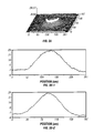
- FIG. 3 ( a ) is a contour graph that illustrates the formation of a bulge, representative of a positive lens, that can form on an output face of a harmonic generator over time.
- FIG. 3 ( b ) is a graphical illustration of the FIG. 3 ( a ) positive lens that can form on the output face of a harmonic generator over time.
- FIG. 4 is a graph that illustrates the principal thermo-optic coefficient at the x-axis for LBO verses temperature.
- FIG. 5 ( a ) is a graph illustrating measurement of harmonic beam divergence at a first temperature T 1 .
- FIG. 5 ( b ) is a graph illustrating the waist diameter of the harmonic beam at temperature T 1 .
- FIG. 5 ( c ) is a graph illustrating M 2 of the harmonic beam at a temperature T 1 .
- FIG. 6 ( a ) is a graph illustrating measurement of harmonic beam divergence at a first temperature T 2 that is less than T 1 .
- FIG. 6 ( b ) is a graph illustrating the waist diameter of the harmonic beam at temperature T 2 .
- FIG. 6 ( c ) is a graph illustrating M 2 of the harmonic beam at a temperature T 2 .
- FIG. 7 ( a ) is a graph illustrating measurement of harmonic beam divergence at a first temperature T 3 that is less than T 2 .
- FIG. 7 ( b ) is a graph illustrating the waist diameter of the harmonic beam at temperature T 3 .
- FIG. 7 ( c ) is a graph illustrating M 2 of the harmonic beam at a temperature T 3 .
- one embodiment of the present invention is a laser system 10 with a high reflector 12 and an output coupler 14 that define a laser oscillator 16 which produces a fundamental beam 18 .
- laser oscillator 16 can be a mode-locked oscillator or a Q-switched oscillator.
- a gain medium 20 is positioned in laser oscillator 16 .
- gain medium 20 is Nd:YVO 4 with a doping less than 0.5%.
- a harmonic generator 22 contains a nonlinear crystal 23 and is positioned to receive at least a portion of fundamental beam 18 to produce a harmonic beam 24 .
- Harmonic generator 22 is configured to operate at a temperature selected to provide a least amount of change of a selected parameter of harmonic beam 24 for the longest period of time.
- the selected temperature is in the range of ⁇ 100 to 200° C.
- the selected parameters can include, the power of harmonic beam 24 , the M 2 of harmonic beam 24 , beam divergence of harmonic beam 24 , and waist size of harmonic beam 24 .
- a plurality of parameters of harmonic beam 24 are utilized in selecting the temperature.
- harmonic generator 22 that includes at least first nonlinear crystal 26 and a second nonlinear crystal 28 .
- First nonlinear crystal 26 produces the second harmonic of fundamental beam 18
- second nonlinear crystal 28 produces the third harmonic of fundamental beam 18 .
- First and second nonlinear crystals 26 and 28 can be made of a variety of different materials, including but not limited to LBO and the like.
- First nonlinear crystal 26 can use Type I phase matching materials
- second nonlinear crystal 28 can use Type II phase matching materials.
- first and second nonlinear crystals 26 and 28 can be critically phase matched.
- an amplifier 30 can be positioned between laser oscillator 16 and harmonic generator 22 .
- Laser oscillator 16 , and amplifier 30 can be pumped by a variety of different sources, including but not limited to, diode sources 32 and 34 .
- Diode sources 32 and 34 can be fiber coupled.
- a diode pump wavelength for Nd:YVO 4 at 809 nm is utilized.
- Higher output power with equivalent thermal lensing can be achieved by pumping directly into the upper laser level, using a wavelength of 880 nm.
- the wavelengths of diode sources 32 and 34 are selected in order to pump directly into the upper laser levels of the gain media in laser oscillator 16 and amplifier 30 .
- a method for selecting a temperature of harmonic generator 22 .
- laser system 10 can be operated at a constant harmonic beam power.
- a change is measured in at least one harmonic beam 24 as a function of time for a plurality of temperatures.
- a temperature is then selected that provides the least amount of change of a selected parameter of harmonic beam 24 for the longest period of time.
- the selected parameters include but are not limited to the M 2 , beam divergence or waist size of harmonic beam 24 .
- a second contribution to the degradation of the beam parameters comes from the bulk of second nonlinear crystal 28 . If a small portion of the UV beam is absorbed in the bulk of second nonlinear crystal 28 , the temperature rises.
- the center of harmonic beam 24 has a higher power than its edges and the temperature is higher in the center.
- the index n, of a second nonlinear crystal 28 is dependent on the temperature T.
- FIG. 4 A plot of the magnitude of this dependence is shown in FIG. 4 .
- the change in index as a function of temperature, dn/dT is zero near room temperature, 20° C. and then becomes negative at higher temperatures. This means that, at a temperature of 50° C., the index of LBO decreases as the temperature increases.
- the index is the lowest. This effect creates a negative thermal lens in the bulk of the second nonlinear crystal 28 and causes the divergence of harmonic beam 24 to increase. For higher temperatures, the negative lens becomes stronger.
- a third contribution to the parameters of harmonic beam 24 comes from the beam parameters of fundamental beam 18 .
- Laser oscillator 16 generates fundamental beam 18 .
- the power of fundamental beam 18 must increase to keep the UV power constant.
- the pump power must be increased. This can be achieved by increasing the power from source 32 .
- the thermal lens in gain medium 20 also changes.
- amplifier 30 is included to increase the power of fundamental beam 18 .
- an increase in the power from diode source 34 affects the magnitude of the thermal lens in amplifier 30 .
- This change in the thermal lens leads to a change in the divergence of fundamental beam 18 that is incident on second nonlinear crystal 28 . This in turn affects the divergence of harmonic beam 24 .
- the present invention balances these effects in order to offset the magnitude of these effects for an extended period of time.
- the deformation on the output surface of the second nonlinear crystal 28 causes harmonic beam 24 to have a smaller divergence.
- the bulk lens causes harmonic beam 24 to have a larger divergence.
- the magnitude of the bulk lens can be changed by changing the temperature of second nonlinear crystal 28 , thus causing the two effects to cancel for an extended period of time.
- the extended period of time is 200 hours or more.
- the exact temperature that cancels the lensing effect depends on several factors. These factors include, (a) the average power of fundamental beam 18 , (b) the size of harmonic beam 24 , (c) the changes required in fundamental beam 18 to keep the UV power constant, and the like.
- the following method was used to determine the optimum temperature to operate second nonlinear crystal 28 for laser system 10 .
- the UV power is constantly measured with a UV detector.
- a servo loop then controls the pump power to the laser oscillator 16 or amplifier 30 in order to keep the UV power constant.
- the parameters of harmonic beam 24 are then measured for an extended period of time, typically 500 hours.
- the measurements are repeated for several different operating temperatures, T 1 , T 2 and T 3 , of second nonlinear crystal 28 , wherein T 1 is greater than T 2 , and T 2 is greater than T 3 .
- the temperatures selected can be in the range of ⁇ 100 to 200° C., and more preferably 0 to 100° C.
- the values of divergence, the beam waist size and the M 2 in both the horizontal, or x direction, and the vertical, or y direction, can be measured periodically.
- the temperature that yields the least amount of change of a selected parameter of harmonic beam 24 for the longest period of time is then selected.
- the power of the UV is kept constant at 4 W for each of these measurements.
- the divergence of the beam may be the most important.
- the first measurement can be done at a temperature of T 1 and is illustrated in FIGS. 5 ( a ) through 5 ( c ).
- FIG. 5 ( a ) shows that the beam divergence of the UV beam increases with time at this temperature.
- the measurement is then repeated at temperature T 2 as shown in FIGS. 6 ( a ) through 6 ( c ). For this temperature the beam divergence is nearly constant with time.
- T 3 is performed at temperature T 3 as shown in FIGS. 7 ( a ) through 7 ( c ). For this temperature, the beam divergence of the UV beam decreases.
- T 2 is selected in order to provide constant divergence.
- the value of M 2 may be the most important.
- the measurements for this parameter at various temperatures are shown in FIGS. 5 ( c ), 6 ( c ) and 7 ( c ).
- the value of M 2 remains constant for nearly 500 hours at a temperature of T 3 . Therefore, T 3 is selected to provide a constant M 2 value.
Abstract
Description
Claims (30)
Priority Applications (3)
| Application Number | Priority Date | Filing Date | Title |
|---|---|---|---|
| US10/061,946 US6697390B2 (en) | 2002-02-01 | 2002-02-01 | Extended lifetime harmonic generator |
| DE10302889A DE10302889A1 (en) | 2002-02-01 | 2003-01-25 | Harmonious generator with extended service life |
| DE10303616A DE10303616A1 (en) | 2002-02-01 | 2003-01-30 | Harmonious generator with extended service life |
Applications Claiming Priority (1)
| Application Number | Priority Date | Filing Date | Title |
|---|---|---|---|
| US10/061,946 US6697390B2 (en) | 2002-02-01 | 2002-02-01 | Extended lifetime harmonic generator |
Publications (2)
| Publication Number | Publication Date |
|---|---|
| US20030147433A1 US20030147433A1 (en) | 2003-08-07 |
| US6697390B2 true US6697390B2 (en) | 2004-02-24 |
Family
ID=22039186
Family Applications (1)
| Application Number | Title | Priority Date | Filing Date |
|---|---|---|---|
| US10/061,946 Expired - Lifetime US6697390B2 (en) | 2002-02-01 | 2002-02-01 | Extended lifetime harmonic generator |
Country Status (2)
| Country | Link |
|---|---|
| US (1) | US6697390B2 (en) |
| DE (2) | DE10302889A1 (en) |
Cited By (2)
| Publication number | Priority date | Publication date | Assignee | Title |
|---|---|---|---|---|
| US20110103413A1 (en) * | 2007-01-19 | 2011-05-05 | Newport Corporation | Quasi-continuous wave ultraviolet light source with optimized output characteristics |
| DE102021201493A1 (en) | 2021-02-17 | 2022-08-18 | Trumpf Laser Gmbh | Method and laser system for generating output laser pulses with an optical component with temperature-dependent power efficiency and associated computer program product |
Families Citing this family (2)
| Publication number | Priority date | Publication date | Assignee | Title |
|---|---|---|---|---|
| US7242700B2 (en) * | 2004-10-05 | 2007-07-10 | Coherent, Inc. | Stabilized frequency-converted laser system |
| FR2938935B1 (en) * | 2008-11-21 | 2011-05-06 | Eolite Systems | DEVICE FOR EXTENDING THE LIFETIME OF A NON-LINEAR OPTICAL SYSTEM SUBJECTED TO RADIATION OF AN INTENSE LASER BEAM AND NON-LINEAR OPTICAL SOURCE COMPRISING SAID DEVICE |
Citations (10)
| Publication number | Priority date | Publication date | Assignee | Title |
|---|---|---|---|---|
| US4913533A (en) * | 1987-12-22 | 1990-04-03 | Spectra-Physics, Inc. | KTP crystal nonlinear optical device with reduced drift and damage |
| US5195104A (en) * | 1991-10-15 | 1993-03-16 | Lasen, Inc. | Internally stimulated optical parametric oscillator/laser |
| US5673281A (en) * | 1996-04-20 | 1997-09-30 | Board Of Trustees Of The Leland Stanford Junior University | Solid state system for frequency conversion using raman-active media and non-linear media |
| US5812308A (en) | 1995-12-20 | 1998-09-22 | Spectra Physics Lasers, Inc. | Mode locked laser and amplifier |
| US5835513A (en) | 1997-01-08 | 1998-11-10 | Spectra Physics, Inc. | Q-switched laser system providing UV light |
| US6185235B1 (en) | 1998-11-24 | 2001-02-06 | Spectra-Physics Lasers, Inc. | Lasers with low doped gain medium |
| US6366596B1 (en) * | 2000-01-21 | 2002-04-02 | Photonics Industries International, Inc. | High power laser |
| US20020141457A1 (en) * | 2001-03-30 | 2002-10-03 | Frank Adams | Method for operating Q-switched lasers with intracavity frequency conversion |
| US20020185701A1 (en) * | 2001-06-07 | 2002-12-12 | Walling John Curtis | Narrow spectral bandwidth tunable pulsed solid-state laser system |
| US20030008448A1 (en) * | 1999-05-27 | 2003-01-09 | Kafka James D. | Remote UV laser system and methods of use |
-
2002
- 2002-02-01 US US10/061,946 patent/US6697390B2/en not_active Expired - Lifetime
-
2003
- 2003-01-25 DE DE10302889A patent/DE10302889A1/en not_active Withdrawn
- 2003-01-30 DE DE10303616A patent/DE10303616A1/en not_active Withdrawn
Patent Citations (10)
| Publication number | Priority date | Publication date | Assignee | Title |
|---|---|---|---|---|
| US4913533A (en) * | 1987-12-22 | 1990-04-03 | Spectra-Physics, Inc. | KTP crystal nonlinear optical device with reduced drift and damage |
| US5195104A (en) * | 1991-10-15 | 1993-03-16 | Lasen, Inc. | Internally stimulated optical parametric oscillator/laser |
| US5812308A (en) | 1995-12-20 | 1998-09-22 | Spectra Physics Lasers, Inc. | Mode locked laser and amplifier |
| US5673281A (en) * | 1996-04-20 | 1997-09-30 | Board Of Trustees Of The Leland Stanford Junior University | Solid state system for frequency conversion using raman-active media and non-linear media |
| US5835513A (en) | 1997-01-08 | 1998-11-10 | Spectra Physics, Inc. | Q-switched laser system providing UV light |
| US6185235B1 (en) | 1998-11-24 | 2001-02-06 | Spectra-Physics Lasers, Inc. | Lasers with low doped gain medium |
| US20030008448A1 (en) * | 1999-05-27 | 2003-01-09 | Kafka James D. | Remote UV laser system and methods of use |
| US6366596B1 (en) * | 2000-01-21 | 2002-04-02 | Photonics Industries International, Inc. | High power laser |
| US20020141457A1 (en) * | 2001-03-30 | 2002-10-03 | Frank Adams | Method for operating Q-switched lasers with intracavity frequency conversion |
| US20020185701A1 (en) * | 2001-06-07 | 2002-12-12 | Walling John Curtis | Narrow spectral bandwidth tunable pulsed solid-state laser system |
Non-Patent Citations (4)
| Title |
|---|
| Ruffing, B. et al., "High-Power Picosecond LiB3O5 Optical Parametric Oscillators Tunable In The Blue Spectral Range" Appl. Phys. B (2000)/ Digital Object Identifier (DOI) 10.1007/s003400000443. |
| Tang, Y. et al., "Thermal Dependence of the Principal Refractive Indices of Lithium Triborate" J. Opt. Soc. Am. B / vol. 12, No. 4 / Apr. 1995. |
| Yapp, Y.K. et al., "Stable Operation of CLBO Crystal For Laser Frequency Conversion at Elevated Temperature" CLEO '97, pp. 512-513. |
| Zhou, W.L., "Intracavity Frequency Doubling of a Continuous Wave Ti:sapphire Laser with over 70% Conversion Efficiency" Appl. Phys. Lett. 66 (19), May 8, 1995, pp. 2463-2465. |
Cited By (4)
| Publication number | Priority date | Publication date | Assignee | Title |
|---|---|---|---|---|
| US20110103413A1 (en) * | 2007-01-19 | 2011-05-05 | Newport Corporation | Quasi-continuous wave ultraviolet light source with optimized output characteristics |
| DE102021201493A1 (en) | 2021-02-17 | 2022-08-18 | Trumpf Laser Gmbh | Method and laser system for generating output laser pulses with an optical component with temperature-dependent power efficiency and associated computer program product |
| WO2022174961A1 (en) | 2021-02-17 | 2022-08-25 | Trumpf Laser Gmbh | Method and laser system for generating output laser pulses using an optical component with temperature-dependent power efficiency, and associated computer program product |
| US11942752B2 (en) | 2021-02-17 | 2024-03-26 | Trumpf Laser Gmbh | Method and laser system for generating output laser pulses with an optical component with temperature-dependent power efficiency and associated computer program product |
Also Published As
| Publication number | Publication date |
|---|---|
| DE10302889A1 (en) | 2003-08-07 |
| US20030147433A1 (en) | 2003-08-07 |
| DE10303616A1 (en) | 2003-08-07 |
Similar Documents
| Publication | Publication Date | Title |
|---|---|---|
| US6816520B1 (en) | Solid state system and method for generating ultraviolet light | |
| USRE35215E (en) | Frequency converted laser diode and lens system therefor | |
| JP6807897B2 (en) | Reduction of laser spectral bandwidth | |
| US7672346B1 (en) | Narrow spectral width lasers optimized and temperature stabilized with volume Bragg grating mirrors | |
| US6697390B2 (en) | Extended lifetime harmonic generator | |
| KR101527224B1 (en) | Method for having laser light source standby status | |
| US5896220A (en) | Production of narrow-band coherent radiation by using at least one optical parametric oscillator | |
| US5805631A (en) | Blue, green, orange, and red upconversion laser | |
| Leplingard et al. | FWM-assisted Raman laser for second-order Raman pumping | |
| US20090046351A1 (en) | Wavelength conversion device and wavelength conversion method | |
| Wang et al. | Study on CW Nd: YAG infrared laser at 1319 nm | |
| KR100831140B1 (en) | Computer readable medium including program for performing optical wavelength conversion | |
| CN111313216B (en) | Method for suppressing intensity noise of high-power continuous wave single-frequency laser | |
| CN110797740B (en) | Intermediate infrared laser based on difference frequency of alkali metal laser | |
| Caprara | 2 W cw OPO in mid-IR pumped by OPSL laser intra-cavity radiation | |
| US5418808A (en) | Solid state laser | |
| JP4474756B2 (en) | Laser light generator | |
| Lancaster et al. | Doppler cooling a single Ca+ ion with a violet extended-cavity diode laser | |
| JP4449614B2 (en) | Wavelength conversion optical system and laser apparatus | |
| JP2000357833A (en) | Wavelength conversion laser device | |
| Uebernickel et al. | 400 mW and 16.5% wavelength conversion efficiency at 488 nm using a diode laser and a PPLN crystal in single pass configuration | |
| Apanasevich et al. | Efficiency of steady-state backward stimulated Raman scattering as a function of the wavelength and spectral linewidth of pump radiation | |
| JP2002223018A (en) | Control system of laser wavelength and control method thereof | |
| JPH08171106A (en) | Wavelength conversion laser | |
| Milton et al. | A tunable injection-seeded optical parametric oscillator between 1.526 μm and 1.578 μm |
Legal Events
| Date | Code | Title | Description |
|---|---|---|---|
| AS | Assignment |
Owner name: SPECTRA PHYSICS LASERS, INC., CALIFORNIA Free format text: ASSIGNMENT OF ASSIGNORS INTEREST;ASSIGNORS:KAFKA, JAMES D.;PETERSEN, ALAN B.;MARKERT, KARL;REEL/FRAME:012789/0786;SIGNING DATES FROM 20020305 TO 20020313 |
|
| STCF | Information on status: patent grant |
Free format text: PATENTED CASE |
|
| FPAY | Fee payment |
Year of fee payment: 4 |
|
| FPAY | Fee payment |
Year of fee payment: 8 |
|
| AS | Assignment |
Owner name: BANK OF AMERICA, N.A., AS ADMINISTRATIVE AGENT, IL Free format text: NOTICE OF GRANT OF SECURITY INTEREST IN PATENTS;ASSIGNOR:NEWPORT CORPORATION;REEL/FRAME:027019/0462 Effective date: 20111004 |
|
| AS | Assignment |
Owner name: NEWPORT CORPORATION, CALIFORNIA Free format text: MERGER AND CHANGE OF NAME;ASSIGNORS:SPECTRA-PHYSICS LASERS, INC.;SPECTRA-PHYSICS, INC.;REEL/FRAME:027845/0487 Effective date: 20070126 |
|
| AS | Assignment |
Owner name: NEWPORT CORPORATION, CALIFORNIA Free format text: RELEASE BY SECURED PARTY;ASSIGNOR:BANK OF AMERICA, N.A., AS ADMINISTRATIVE AGENT;REEL/FRAME:030833/0421 Effective date: 20130718 |
|
| AS | Assignment |
Owner name: JPMORGAN CHASE BANK, NATIONAL ASSOCIATION, AS ADMI Free format text: SECURITY AGREEMENT;ASSIGNOR:NEWPORT CORPORATION;REEL/FRAME:030847/0005 Effective date: 20130718 |
|
| FPAY | Fee payment |
Year of fee payment: 12 |
|
| AS | Assignment |
Owner name: NEWPORT CORPORATION, CALIFORNIA Free format text: RELEASE BY SECURED PARTY;ASSIGNOR:JPMORGAN CHASE BANK N.A., AS ADMINISTRATIVE AGENT;REEL/FRAME:038581/0112 Effective date: 20160429 |
|
| AS | Assignment |
Owner name: BARCLAYS BANK PLC, NEW YORK Free format text: SECURITY AGREEMENT;ASSIGNORS:MKS INSTRUMENTS, INC.;NEWPORT CORPORATION;REEL/FRAME:038663/0139 Effective date: 20160429 Owner name: DEUTSCHE BANK AG NEW YORK BRANCH, NEW YORK Free format text: SECURITY AGREEMENT;ASSIGNORS:MKS INSTRUMENTS, INC.;NEWPORT CORPORATION;REEL/FRAME:038663/0265 Effective date: 20160429 |
|
| AS | Assignment |
Owner name: BARCLAYS BANK PLC, AS COLLATERAL AGENT, NEW YORK Free format text: PATENT SECURITY AGREEMENT (ABL);ASSIGNORS:ELECTRO SCIENTIFIC INDUSTRIES, INC.;MKS INSTRUMENTS, INC.;NEWPORT CORPORATION;REEL/FRAME:048211/0312 Effective date: 20190201 Owner name: NEWPORT CORPORATION, CALIFORNIA Free format text: RELEASE BY SECURED PARTY;ASSIGNOR:DEUTSCHE BANK AG NEW YORK BRANCH;REEL/FRAME:048226/0095 Effective date: 20190201 Owner name: MKS INSTRUMENTS, INC., MASSACHUSETTS Free format text: RELEASE BY SECURED PARTY;ASSIGNOR:DEUTSCHE BANK AG NEW YORK BRANCH;REEL/FRAME:048226/0095 Effective date: 20190201 |
|
| AS | Assignment |
Owner name: BARCLAYS BANK PLC, AS COLLATERAL AGENT, NEW YORK Free format text: CORRECTIVE ASSIGNMENT TO CORRECT THE REMOVE U.S. PATENT NO.7,919,646 PREVIOUSLY RECORDED ON REEL 048211 FRAME 0312. ASSIGNOR(S) HEREBY CONFIRMS THE PATENT SECURITY AGREEMENT (ABL);ASSIGNORS:ELECTRO SCIENTIFIC INDUSTRIES, INC.;MKS INSTRUMENTS, INC.;NEWPORT CORPORATION;REEL/FRAME:055668/0687 Effective date: 20190201 |
|
| AS | Assignment |
Owner name: JPMORGAN CHASE BANK, N.A., AS COLLATERAL AGENT, ILLINOIS Free format text: SECURITY INTEREST;ASSIGNORS:MKS INSTRUMENTS, INC.;NEWPORT CORPORATION;ELECTRO SCIENTIFIC INDUSTRIES, INC.;REEL/FRAME:061572/0069 Effective date: 20220817 |
|
| AS | Assignment |
Owner name: ELECTRO SCIENTIFIC INDUSTRIES, INC., OREGON Free format text: RELEASE BY SECURED PARTY;ASSIGNOR:BARCLAYS BANK PLC;REEL/FRAME:063009/0001 Effective date: 20220817 Owner name: NEWPORT CORPORATION, MASSACHUSETTS Free format text: RELEASE BY SECURED PARTY;ASSIGNOR:BARCLAYS BANK PLC;REEL/FRAME:063009/0001 Effective date: 20220817 Owner name: MKS INSTRUMENTS, INC., MASSACHUSETTS Free format text: RELEASE BY SECURED PARTY;ASSIGNOR:BARCLAYS BANK PLC;REEL/FRAME:063009/0001 Effective date: 20220817 Owner name: ELECTRO SCIENTIFIC INDUSTRIES, INC., OREGON Free format text: RELEASE BY SECURED PARTY;ASSIGNOR:BARCLAYS BANK PLC;REEL/FRAME:062739/0001 Effective date: 20220817 Owner name: NEWPORT CORPORATION, MASSACHUSETTS Free format text: RELEASE BY SECURED PARTY;ASSIGNOR:BARCLAYS BANK PLC;REEL/FRAME:062739/0001 Effective date: 20220817 Owner name: MKS INSTRUMENTS, INC., MASSACHUSETTS Free format text: RELEASE BY SECURED PARTY;ASSIGNOR:BARCLAYS BANK PLC;REEL/FRAME:062739/0001 Effective date: 20220817 |