US6700623B1 - Video signal processing using triplets of pixels - Google Patents
Video signal processing using triplets of pixels Download PDFInfo
- Publication number
- US6700623B1 US6700623B1 US09/581,045 US58104500A US6700623B1 US 6700623 B1 US6700623 B1 US 6700623B1 US 58104500 A US58104500 A US 58104500A US 6700623 B1 US6700623 B1 US 6700623B1
- Authority
- US
- United States
- Prior art keywords
- pixels
- filter
- weighted sum
- interpolation
- video
- Prior art date
- Legal status (The legal status is an assumption and is not a legal conclusion. Google has not performed a legal analysis and makes no representation as to the accuracy of the status listed.)
- Expired - Lifetime
Links
Images

Classifications
-
- H—ELECTRICITY
- H04—ELECTRIC COMMUNICATION TECHNIQUE
- H04N—PICTORIAL COMMUNICATION, e.g. TELEVISION
- H04N7/00—Television systems
- H04N7/01—Conversion of standards, e.g. involving analogue television standards or digital television standards processed at pixel level
- H04N7/0117—Conversion of standards, e.g. involving analogue television standards or digital television standards processed at pixel level involving conversion of the spatial resolution of the incoming video signal
- H04N7/012—Conversion between an interlaced and a progressive signal
Definitions
- This invention relates to video signal processing and especially to processes of interpolation, particularly spatial interpolation, whether horizontal, vertical or two dimensional.
- the invention applies in an important example to the process of de-interlacing by which a video frame is derived for each field of an interlaced video signal.
- a known de-interlacing technique derives the “missing” lines through a weighted sum of neighbouring sample points.
- the location of the sample points to be employed and the values of the weighting coefficients are chosen to minimise visual artefacts and certain design principles have been established.
- the present invention consists in one aspect in a video process wherein a weighted sum of pixels from at least one input picture is taken in a filter aperture to generate a pixel in an output picture, characterised in that the weighted sum includes products of triplets of pixels.
- a video frame is derived through spatial interpolation from each video field of an interlaced input signal.
- the weighted sum comprises pixels and products of triplets of pixels.
- the present invention consists in a video process of interpolation, wherein adaption is provided between a process of spatial interpolation in which a weighted sum of products of pixels from an input picture is taken in a filter aperture to generate a pixel in an output picture, and a process of temporal interpolation which a weighted sum of pixels from two or more input pictures is taken in a filter aperture to generate a pixel in an output picture.
- the present invention consists in video signal processing apparatus for interpolation, comprising an interpolation filter taking a weighted sum of pixels from at least one input picture in a filter aperture, to generate a pixel in an output picture, characterised in that the weighted sum includes products of triplets of pixels.
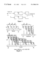
- FIG. 1 is a diagram of a de-interlacing circuit according to the present invention.
- FIG. 2 is a diagrammatical representation of a four tap third order filter useful in accordance with the present invention.
- FIG. 3 is a diagram illustrating a process for designing a filter according to the present invention.
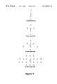
- FIG. 4 is a series of diagrams illustrating filter apertures for use in the present invention.
- FIG. 5 is a diagram of an interpolating circuit according to one embodiment of the present invention.
- FIG. 6 is a diagram of an interpolating circuit according to a further embodiment of the present invention.
- the aim is to interpolate one field of a video frame from another. This is known as de-interlacing.
- FIG. 1 a de-interlacing circuit in which an interlaced video signal at input terminal 10 is operated upon to form a progressive signal at output terminal 12 .
- a filter 14 receives one field of a video frame and from it interpolates the other field of the frame.
- a multiplexer 16 receives these “new” fields, as well as the original fields (appropriately delayed at 18 ). The output of the multiplexer is a progressive scan video signal.
- the filter 14 is linear, each filter tap (derived by appropriate delay elements from the input video) is multiplied by a filter weight and the resulting products are summed to give the filter output.
- the present invention proposes a polynomial non-linear filter. This includes, in addition to the linear terms, the sum of filter coefficients multiplied by products of pixel values, triplets of pixel values, etc.
- a four tap filter for use in the present invention will contain four filter coefficients which are multiplied by single pixel values, ten filter coefficients which are multiplied by products of pixel values, twenty filter coefficients which are multiplied by triplets of pixel values, etc.
- the polynomial series must be truncated at some point.
- a filter truncated at the third order is convenient and there is shown diagrammatically in FIG. 2, a four tap third order filter for use as filter 14 of FIG. 1 .
- the polynomial filter is illustrated graphically as the combination of a linear filter 100 , a quadratic filter 102 and a cubic filter 103 .
- the linear filter utilises three delay elements 104 to generate four taps from the input signal. Each tap is multiplied by a coefficient in a respective multiplier 105 and a weighted sum generated in summing device 106 .
- Similar delay elements 114 provide four taps from the input video signal and ten multipliers 115 generate all ten possible products, again weighted by respective coefficients. A sum is formed in summing device 116 .
- the cubic filter has twenty multipliers 125 operating on the taps from delay elements 124 to generate all possible combinations of triplets of taps and a weighted sum is formed in summing device 126 .
- the delay elements 104 , 114 and 124 have been shown separately in the three filters, one set of delay elements would usually suffice.
- a single processing element will receive the four taps and with appropriate multipliers, coefficient stores and one or more summing devices, output directly the sum of the linear, quadratic and
- the object is to design an N point digital finite impulse response filter, h, to modify the input, x(n), in such a way as to minimise the mean square error, e(n), between the filter output and the desired signal, y(n).
- x(n) is field f 1
- y(n) is field f 2 .
- the aim is to create a filter h(n) that when operated on f 1 , gives the best possible estimate of f 2 such that the mean squared error between the estimate of f 2 and actual f 2 is minimised.
- a progressive input is proved to block 30 which separates the fields of a video frame and outputs field f 1 and field f 2 .
- Field f 1 that is to say x(n) is provided to the filter 32 to generate an estimate of f 2 . This is then compared in block 34 with the actual f 2 , that is to say y(n).
- X T X and X T y are usually much smaller than X. Hence, it is much more efficient to compute X T X and X T y directly from x(n) and (n) rather than to form X.
- the filter will contain three separate components; the DC term, the standard linear coefficients which should be multiplied by single pixel values, and the quadratic coefficients which will be multiplied by product of pixel values.
- the present invention recognises that if the mean square error is chosen for optimisation of the filter, it is possible to calculate the filter coefficients h without forming a trial filter and iterating.
- the training process then represents not an iterative improvement in a trial or prototype filter, but the collection of sufficient data from real picture material for which both x and y are known, to enable calculation of meaningful auto-correlation matrix and cross correlation vector.
- a polynomial model truncated at the third order is preferred according to this invention.
- This will contain linear, quadratic, and cubic filters and so is able to model systems which contain both quadratic and cubic non-linear elements. These generate both skewed and symmetric distortions of the probability density function.
- Higher order models can be used and are shown to give improved results but the size of the filter and the computation required in its estimation rise exponentially and there are rapidly diminishing returns.
- the fifth order, six pixel cubic non-linear filter does perform better than the third order, six pixel filter but there are over five times as many terms.
- Table 2 shows the mean squared error between the estimated field and actual field for a particular reference picture, for a series of different filters. It can be seen that in all cases, the non-linear filters perform better than standard linear filters.
- non-linear filter produces much smoother edges and curves than its linear counterpart, with reduced jagging.
- Non-linear polynomial filters in accordance with the present invention can give dramatically improved performance over conventional linear predictors when used for spatial de-interlacing.
- Polynomial non-linear filters are generally more complex than their linear equivalents, although only using spatial information reduces the complexity significantly as compared to conventional spatio-temporal filters. The increased performance seems to occur mainly along edges; whereas linear filters often produce jagging on diagonal lines and curves, the nonlinear filters described here considerably reduce such artifacts.
- a non-linear filter for use in the present invention can be implemented directly as a set of multipliers and an adder as so far described or the same charateristic can be achieved using a lookup table.
- a de-interlacing circuit can operate independently or the de-interlacing function can be incorporated within a circuit operating on an interlaced signal for the purposes of standards conversion, upconversion, downconversion, aspect ratio conversion, digital video effects and so on.
- FIG. 5 there is shown a circuit which operates on an interlaced video signal received at input terminal 500 to provide through interpolation an output video signal at terminal 502 .
- This may be an interlace or a progressive signal and may have different numbers of lines per field, different numbers of fields per second and so on, depending upon the specific function of the circuit.
- One example would be an interlaced output in a different television broadcast standard to the input.
- the input signal of FIG. 5 is passed to a polynomial filter 504 that in one example takes the form illustrated symbolically in FIG. 2 .
- the output of filter 504 comprising the “new” fields, passes through a FIFO 506 to a series chain of delay elements 508 .
- the original fields are taken through a delay 514 to a similar FIFO 516 and delay elements 518 .
- a weighted sum of the filter taps generated by the delay elements 508 and 518 is taken by means of multipliers 520 and summing device 522 .
- the output of the summing device 522 is taken through a FIFO 524 , to the output terminal.
- the coefficients of the multipliers are set through control unit 526 , which also serves to control the rates at which data is read into and read out of the FIFO's 506 , 516 and 524 .
- an interpolating circuit has the interlaced video input signal at terminal 600 passing through FIFO 602 to a polynomial filter 604 .
- a polynomial filter 604 This may be of the same general form as FIG. 2 but with each of the multipliers receiving its multiplication coefficient dynamically from a control unit 606 .
- the output of the filter 604 passes through a further FIFO 608 with the control unit 606 controlling the rates at which data is read into and read out of the FIFO's 602 and 608 .
- a temporal interpolator can be produced. It is known that the performance of a de-interlacer can be improved for still material by employing temporal interpolation. It is then necessary to detect motion and to adapt or switch on detection of motion from temporal interpolation. This motion adaption is preferably conducted With prior art techniques, this switching or adaptation produces adaption artefacts that can be visually disturbing. It is found that by using a spatial interpolator according to the present invention, and preferably also a temporal interpolator using a similar polynomial filter, the visibility of adaption artefacts is considerably reduced.
- an interpolator provides a “fine” adaption, inasmuch as the value of a pixel in a product of two pixels can be regarded as varying the multiplication coefficient applied to the other pixel.
- Adaption in the conventional sense from temporal to spatial interpolation can in this sense be regarded as “coarse” adaption.
- coarse adaption might be regarded as switching from +5 to ⁇ 5, which is a step large enough to produce switching artefacts.
- de-interlacing is not the only application for apparatus according to the present invention. It may be more regarded as useful with an input video signal which is undersampled, de-interlacing being then only one example.
Abstract
A de-interlacing process takes a weighted sum of pixels in a filter aperture to generate a pixel in an output picture, the weighted sum including products of triplets of pixels. Using a training sequence of progressive material, it is possible to calculate the weighting coefficients necessary to minimize the mean square error between the filter output and the desired result.
Description
This invention relates to video signal processing and especially to processes of interpolation, particularly spatial interpolation, whether horizontal, vertical or two dimensional. The invention applies in an important example to the process of de-interlacing by which a video frame is derived for each field of an interlaced video signal.
A known de-interlacing technique derives the “missing” lines through a weighted sum of neighbouring sample points. The location of the sample points to be employed and the values of the weighting coefficients are chosen to minimise visual artefacts and certain design principles have been established.
Adaptive techniques have emerged by which the characteristics of the de-interlacing filter are changed in the face of—for example—motion.
It is an object of aspects of the present invention to provide improved video signal processing by which the appearance of visual artefacts on spatial interpolation is further minimised.
It is a further object of one aspect of the present invention to provide improved video signal processing by which a video frame is derived for each field of an interlaced video signal.
Accordingly, the present invention consists in one aspect in a video process wherein a weighted sum of pixels from at least one input picture is taken in a filter aperture to generate a pixel in an output picture, characterised in that the weighted sum includes products of triplets of pixels.
Suitably, a video frame is derived through spatial interpolation from each video field of an interlaced input signal.
In one form of the invention, the weighted sum comprises pixels and products of triplets of pixels.
In another aspect, the present invention consists in a video process of interpolation, wherein adaption is provided between a process of spatial interpolation in which a weighted sum of products of pixels from an input picture is taken in a filter aperture to generate a pixel in an output picture, and a process of temporal interpolation which a weighted sum of pixels from two or more input pictures is taken in a filter aperture to generate a pixel in an output picture.
In yet another aspect, the present invention consists in video signal processing apparatus for interpolation, comprising an interpolation filter taking a weighted sum of pixels from at least one input picture in a filter aperture, to generate a pixel in an output picture, characterised in that the weighted sum includes products of triplets of pixels.
This invention will now be described by way of example with reference to the accompanying drawings, in which:
FIG. 1 is a diagram of a de-interlacing circuit according to the present invention;
FIG. 2 is a diagrammatical representation of a four tap third order filter useful in accordance with the present invention;
FIG. 3 is a diagram illustrating a process for designing a filter according to the present invention;
FIG. 4 is a series of diagrams illustrating filter apertures for use in the present invention;
FIG. 5 is a diagram of an interpolating circuit according to one embodiment of the present invention; and
FIG. 6 is a diagram of an interpolating circuit according to a further embodiment of the present invention.
In one embodiment of this invention, the aim is to interpolate one field of a video frame from another. This is known as de-interlacing.
There is shown in FIG. 1, a de-interlacing circuit in which an interlaced video signal at input terminal 10 is operated upon to form a progressive signal at output terminal 12. A filter 14 receives one field of a video frame and from it interpolates the other field of the frame. A multiplexer 16 receives these “new” fields, as well as the original fields (appropriately delayed at 18). The output of the multiplexer is a progressive scan video signal.
In a traditional de-interlacing circuit, the filter 14 is linear, each filter tap (derived by appropriate delay elements from the input video) is multiplied by a filter weight and the resulting products are summed to give the filter output. In contrast, the present invention proposes a polynomial non-linear filter. This includes, in addition to the linear terms, the sum of filter coefficients multiplied by products of pixel values, triplets of pixel values, etc. For example, a four tap filter for use in the present invention will contain four filter coefficients which are multiplied by single pixel values, ten filter coefficients which are multiplied by products of pixel values, twenty filter coefficients which are multiplied by triplets of pixel values, etc.
In any practical embodiment, the polynomial series must be truncated at some point. A filter truncated at the third order is convenient and there is shown diagrammatically in FIG. 2, a four tap third order filter for use as filter 14 of FIG. 1. The polynomial filter is illustrated graphically as the combination of a linear filter 100, a quadratic filter 102 and a cubic filter 103. The linear filter utilises three delay elements 104 to generate four taps from the input signal. Each tap is multiplied by a coefficient in a respective multiplier 105 and a weighted sum generated in summing device 106. In the quadratic filter 102, similar delay elements 114 provide four taps from the input video signal and ten multipliers 115 generate all ten possible products, again weighted by respective coefficients. A sum is formed in summing device 116. The cubic filter has twenty multipliers 125 operating on the taps from delay elements 124 to generate all possible combinations of triplets of taps and a weighted sum is formed in summing device 126. Although the delay elements 104, 114 and 124 have been shown separately in the three filters, one set of delay elements would usually suffice.
It will be understood that in any practical circuit there are very many ways of embodying the described filter. Typically, a single processing element will receive the four taps and with appropriate multipliers, coefficient stores and one or more summing devices, output directly the sum of the linear, quadratic and
To understand the technique of constructing a filter according to the present invention, it is helpful to look at FIG. 3. The object is to design an N point digital finite impulse response filter, h, to modify the input, x(n), in such a way as to minimise the mean square error, e(n), between the filter output and the desired signal, y(n). In the case of de-interlacing, x(n) is field f1, and y(n) is field f2. The aim is to create a filter h(n) that when operated on f1, gives the best possible estimate of f2 such that the mean squared error between the estimate of f2 and actual f2 is minimised. In FIG. 3, a progressive input is proved to block 30 which separates the fields of a video frame and outputs field f1 and field f2. Field f1, that is to say x(n) is provided to the filter 32 to generate an estimate of f2. This is then compared in block 34 with the actual f2, that is to say y(n).
The filter impulse response which minimises the sum of the squared errors of data of length L, is given by the solution of the over-determined (assuming L>N) system of equations 
the least squares solution of which is,
where XTX=R is known as the auto-correlation matrix and XTy=p is known as he cross correlation vector. Note XTX and XTy are usually much smaller than X. Hence, it is much more efficient to compute XTX and XTy directly from x(n) and (n) rather than to form X.
The extension of this to a more general non-linear model is in principle simply a matter of modifying the data matrix X. Below we show the data matrix for a second order polynomial non-linear filter, in which a constant (DC) term has also been included. A symmetric form for the non-linear components of the filter has been assumed so this matrix has dimension 

The optimal filter, in the least squares sense, can then be estimated by solving h=R−1p. The filter will contain three separate components; the DC term, the standard linear coefficients which should be multiplied by single pixel values, and the quadratic coefficients which will be multiplied by product of pixel values.
The present invention recognises that if the mean square error is chosen for optimisation of the filter, it is possible to calculate the filter coefficients h without forming a trial filter and iterating. The training process then represents not an iterative improvement in a trial or prototype filter, but the collection of sufficient data from real picture material for which both x and y are known, to enable calculation of meaningful auto-correlation matrix and cross correlation vector.
A polynomial model truncated at the third order is preferred according to this invention. This will contain linear, quadratic, and cubic filters and so is able to model systems which contain both quadratic and cubic non-linear elements. These generate both skewed and symmetric distortions of the probability density function. Higher order models can be used and are shown to give improved results but the size of the filter and the computation required in its estimation rise exponentially and there are rapidly diminishing returns. For example, the fifth order, six pixel cubic non-linear filter does perform better than the third order, six pixel filter but there are over five times as many terms.
For the linear case, it is found that neither increasing the number of taps in the vertical direction, of a six point vertical filter nor utilising pixels in the horizontal direction, significantly reduces the mean squared error. However, for a filter according to the present invention, the choice of aperture has much more dramatic results. For example, a two dimensional aperture does give a significant improvement over a one dimensional one. This is thought to be due to the ability of the non-linear filter to deal with sloping edges and lines and utilise gradient information.
However, as can be seen in Table 1, the number of filter coefficients rises exponentially with the number of pixels. Due to computational constraints a sensible maximum size is presently taken for a cubic filter of 20 pixels and for a fifth order filter, 6 pixels.
| Total number of filter coefficients for third and fifth order |
| non-linear filters containing 4,6,8,12 and 20 pixels. |
| Number of filter coefficients |
| No. of pixels | Third order non-linear filter | Fifth order |
| 4 | 35 | 126 |
| 6 | 84 | 462 |
| 8 | 165 | 1287 |
| 12 | 445 | 6178 |
| 20 | 1770 | 53129 |
As the number of pixels available is limited it is important to choose the correct shape of aperture. Best results seem to occur from apertures that contain four vertical pixels and then a number of horizontal pixels. The apertures used for the 4, 6, 8 and 20 pixel filters are shown in FIG. 4 (X denotes the pixels used in field, f1, to estimate the pixel denoted by O in field, f2). The use of horizontal information helps to cope with the near horizontal lines and edges that often cause problems due to jagging in de-interlacing.
Table 2 shows the mean squared error between the estimated field and actual field for a particular reference picture, for a series of different filters. It can be seen that in all cases, the non-linear filters perform better than standard linear filters.
| TABLE 2 |
| Mean squared errors for various filters used on EBU |
| reference picture “Girl”. |
| Mean squared | ||
| error between the | ||
| estimate of the | Number of | |
| field and the actual | coefficients | |
| Filter type | field | in filter |
| 2 pixel linear filter (0.5/0.5) | 23.15 | 2 |
| 4 pixel linear filter (optimum) | 18.61 | 4 |
| 8 pixel linear filter (optimum) | 18.58 | 8 |
| 36 pixel linear filter (optimum) | 18.55 | 36 |
| 4 pixel cubic filter (optimum) | 16.14 | 35 |
| 6 pixel cubic filter (optimum) | 15.67 | 84 |
| 6 pixel fifth order filter (optimum) | 14.88 | 462 |
| 8 pixel cubic filter (optimum) | 15.21 | 165 |
| 12 pixel cubic filter (optimum) | 14.69 | 445 |
| 20 pixel cubic filter (optimum) | 13.50 | 1770 |
It is found that the non-linear filter produces much smoother edges and curves than its linear counterpart, with reduced jagging.
Finally, the mean square error is given for a series of pictures for a linear, and two non-linear filters, (Table 3). It can be seen that in all cases the non-linear filters perform as well as or better than the linear filters.
| TABLE 3 |
| Mean squared error for standard EBU |
| pictures |
| Error for | Error for | Error for | |||
| |
4 pixel linear | 4 pixel cubic | 12 pixel cubic | ||
| Blackboard | 49 | 43 | 43 | ||
| Boats | 73 | 67 | 66 | ||
| Boy | 73 | 64 | 57 | ||
| Clown | 23 | 20 | 20 | ||
| Girl | 19 | 17 | 17 | ||
| Pond | 166 | 153 | 140 | ||
| Tree | 313 | 303 | 303 | ||
| couple | 91 | 87 | 86 | ||
| Kiel | 135 | 128 | 128 | ||
| Latin | 363 | 289 | 234 | ||
Non-linear polynomial filters in accordance with the present invention can give dramatically improved performance over conventional linear predictors when used for spatial de-interlacing. Polynomial non-linear filters are generally more complex than their linear equivalents, although only using spatial information reduces the complexity significantly as compared to conventional spatio-temporal filters. The increased performance seems to occur mainly along edges; whereas linear filters often produce jagging on diagonal lines and curves, the nonlinear filters described here considerably reduce such artifacts.
A non-linear filter for use in the present invention can be implemented directly as a set of multipliers and an adder as so far described or the same charateristic can be achieved using a lookup table.
A de-interlacing circuit can operate independently or the de-interlacing function can be incorporated within a circuit operating on an interlaced signal for the purposes of standards conversion, upconversion, downconversion, aspect ratio conversion, digital video effects and so on.
Thus, turning to FIG. 5, there is shown a circuit which operates on an interlaced video signal received at input terminal 500 to provide through interpolation an output video signal at terminal 502. This may be an interlace or a progressive signal and may have different numbers of lines per field, different numbers of fields per second and so on, depending upon the specific function of the circuit. One example would be an interlaced output in a different television broadcast standard to the input.
The input signal of FIG. 5 is passed to a polynomial filter 504 that in one example takes the form illustrated symbolically in FIG. 2. The output of filter 504, comprising the “new” fields, passes through a FIFO 506 to a series chain of delay elements 508. The original fields are taken through a delay 514 to a similar FIFO 516 and delay elements 518.
A weighted sum of the filter taps generated by the delay elements 508 and 518 is taken by means of multipliers 520 and summing device 522. The output of the summing device 522 is taken through a FIFO 524, to the output terminal. The coefficients of the multipliers are set through control unit 526, which also serves to control the rates at which data is read into and read out of the FIFO's 506, 516 and 524.
The skilled man will recognize that through appropriate choice of the delay elements and control of the FIFO's and multipliers, a wide variety of interpolation procedures can be conducted.
In another arrangement, the interpolation process is “folded into” the polynomial filter. Thus as shown in FIG. 6, an interpolating circuit has the interlaced video input signal at terminal 600 passing through FIFO 602 to a polynomial filter 604. This may be of the same general form as FIG. 2 but with each of the multipliers receiving its multiplication coefficient dynamically from a control unit 606. The output of the filter 604 passes through a further FIFO 608 with the control unit 606 controlling the rates at which data is read into and read out of the FIFO's 602 and 608.
In still a further modification, selecting at least some of the delay elements of the filter to be field delays rather than pixel or line delays, a temporal interpolator can be produced. It is known that the performance of a de-interlacer can be improved for still material by employing temporal interpolation. It is then necessary to detect motion and to adapt or switch on detection of motion from temporal interpolation. This motion adaption is preferably conducted With prior art techniques, this switching or adaptation produces adaption artefacts that can be visually disturbing. It is found that by using a spatial interpolator according to the present invention, and preferably also a temporal interpolator using a similar polynomial filter, the visibility of adaption artefacts is considerably reduced. It is believed that the described non-linear behaviour of an interpolator according to the present invention provides a “fine” adaption, inasmuch as the value of a pixel in a product of two pixels can be regarded as varying the multiplication coefficient applied to the other pixel. Adaption in the conventional sense from temporal to spatial interpolation can in this sense be regarded as “coarse” adaption. Taking numerals as an illustration, coarse adaption might be regarded as switching from +5 to −5, which is a step large enough to produce switching artefacts. Consider now that the two values of +5 and −5 are both subject to fine adaption in the range 0,1,2,3,4,5,6,7,8,9 in the case of the +5 value, and −9,−8,−7,−6,−5,−4,−3,−2−1,0 in the case of the −5 value. Now, in face of a tendency dictating a switch from +5 to −5, it is to be expected that fine adaption will have occurred in the +5 value towards 0, thus minimising the switch step. If the −5 value has similarly undergone fine adaption towards 0, the step will be further reduced.
Whilst an important example, de-interlacing is not the only application for apparatus according to the present invention. It may be more regarded as useful with an input video signal which is undersampled, de-interlacing being then only one example.
Claims (19)
1. A video process comprising the steps of taking a weighted sum of pixels from at least one input picture in a filter aperture, and using said weighted sum to generate a pixel in an output picture, characterised in that the weighted sum includes products of triplets of pixels, said products of triplets of pixels comprising the multiplicative product of three pixels multiplied by each other.
2. A video process according to claim 1 , in which spatial interpolation is conducted.
3. A video process according to claim 2 , in which a video frame is derived through spatial interpolation from each video field of an interlaced input signal.
4. A video process according to claim 1 , wherein the weighted sum comprises pixels and products of triplets of pixels.
5. A video process of interpolation comprising a process step of spatial interpolation in which a weighted sum of products of pixels multiplied by each other from an input picture is taken in a filter aperture to generate a pixel in an output picture, an adaption step of switching between spatial interpolation and temporal interpolation, and a process step of temporal interpolation in which a weighted sum of pixels from two or more input pictures is taken in a filter aperture to generate a pixel in an output picture.
6. A video process according to claim 5 , wherein said spatial interpolation takes a weighted sum of products of triplets of pixels from said input picture.
7. A video process according to claim 5 , wherein said temporal interpolation takes a weighted sum of products of pixels from two or more input pictures.
8. A video process according to claim 7 , wherein said temporal interpolation takes a weighted sum of products of triplets of pixels from two or more input pictures.
9. A video process according to claim 5 , in which said adaption step is performed in response to motion.
10. A video process according to claim 9 , wherein said adaption step is performed substantially pixel by pixel.
11. Video signal processing apparatus for interpolation, comprising an interpolation filter taking a weighted sum of pixels from at least one input picture in a filter aperture, to generate a pixel in an output picture, characterised in that the weighted sum includes products of triplets of pixels, said products of triplets of pixels comprising the multiplicative product of three pixels multiplied by each other.
12. Video signal processing apparatus according to claim 11 , wherein said triplets of pixels are from the same picture.
13. Video signal processing apparatus according to claim 11 , wherein the filter is continuously in circuit, during operation of the apparatus.
14. A video process of interpolation, having training and interpolating modes, comprising the steps of:
in the training mode, inputting into a video signal processing apparatus having a weighted filter, an undersampled picture from which a known desired picture to be interpolated, and optimising the filter weightings of the weighted filter to minimise an error between said known picture and an output of the video signal processing apparatus; and
in an interpolating mode, operating the filter with optimised parameters on an input signal.
15. A process according to claim 14 , wherein the error that is minimised is a mean square error.
16. An interpolating filter employing weighting coefficients h, operating on an undersampled video signal x, there being correctly sampled information available for at least a training sequence of x to generate the desired result y of an interpolation process on x, the filter taking weighted sums of products of N pixels multiplied by each other in a filter aperture; the coefficients h employed in the weighting being derived according to h=(XTX)−1XTy where X is the matrix of N pixels of the signal x over the training sequence.
17. A filter according to claim 16 , wherein the matrix X includes products of pairs of pixels.
18. A filter according to claim 16 , wherein the matrix X includes products of triplets of pixels.
19. A method of processing video information, the method comprising:
spatially interpolating an input picture taken in a filter aperture by multiplying a weighted sum of products of pixels by each other to generate a pixel in an output picture;
switching between spatial interpolation and temporal interpolation; and
temporally interpolating a weighted sum of pixels from two or more input pictures taken in a filter aperture to generate a pixel in an output picture.
Applications Claiming Priority (1)
| Application Number | Priority Date | Filing Date | Title |
|---|---|---|---|
| PCT/GB1998/003691 WO1999030490A1 (en) | 1997-12-10 | 1998-12-10 | Video signal processing |
Publications (1)
| Publication Number | Publication Date |
|---|---|
| US6700623B1 true US6700623B1 (en) | 2004-03-02 |
Family
ID=31726466
Family Applications (1)
| Application Number | Title | Priority Date | Filing Date |
|---|---|---|---|
| US09/581,045 Expired - Lifetime US6700623B1 (en) | 1998-12-10 | 1998-12-10 | Video signal processing using triplets of pixels |
Country Status (1)
| Country | Link |
|---|---|
| US (1) | US6700623B1 (en) |
Cited By (3)
| Publication number | Priority date | Publication date | Assignee | Title |
|---|---|---|---|---|
| US20030160895A1 (en) * | 2002-02-25 | 2003-08-28 | Yiwei Wang | Adaptive median filters for de-interlacing |
| US20060008178A1 (en) * | 2004-07-08 | 2006-01-12 | Seeger Adam A | Simulation of scanning beam images by combination of primitive features extracted from a surface model |
| US20080246876A1 (en) * | 2007-04-04 | 2008-10-09 | Freescale Semiconductor, Inc. | Video de-interlacer using pixel trajectory |
Citations (29)
| Publication number | Priority date | Publication date | Assignee | Title |
|---|---|---|---|---|
| US5086488A (en) | 1989-08-19 | 1992-02-04 | Mitsubishi Denki Kabushiki Kaisha | Transform coding apparatus |
| US5142380A (en) | 1989-10-23 | 1992-08-25 | Ricoh Company, Ltd. | Image data processing apparatus |
| US5226114A (en) | 1989-10-13 | 1993-07-06 | Massachusetts Institute Of Technology | Television pictures |
| US5249053A (en) | 1991-02-05 | 1993-09-28 | Dycam Inc. | Filmless digital camera with selective image compression |
| EP0651577A2 (en) | 1993-10-27 | 1995-05-03 | Texas Instruments Incorporated | Digital television system |
| US5438625A (en) | 1991-04-09 | 1995-08-01 | Jbl, Incorporated | Arrangement to correct the linear and nonlinear transfer behavior or electro-acoustical transducers |
| US5512956A (en) | 1994-02-04 | 1996-04-30 | At&T Corp. | Adaptive spatial-temporal postprocessing for low bit-rate coded image sequences |
| US5519647A (en) | 1993-05-12 | 1996-05-21 | U.S. Philips Corporation | Apparatus for and method of generating an approximation function |
| WO1997001929A1 (en) | 1995-06-29 | 1997-01-16 | Motorola Inc. | Circuit for interpolating scan lines of a video signal and method of using same |
| US5621470A (en) | 1992-12-18 | 1997-04-15 | Sid-Ahmed; Maher A. | Interpixel and interframe interpolation of television pictures with conversion from interlaced to progressive scanning |
| WO1997016923A1 (en) | 1995-11-01 | 1997-05-09 | Philips Electronics N.V. | Video signal scan conversion |
| US5629779A (en) | 1994-01-12 | 1997-05-13 | Samsung Electronics Co., Ltd. | Image coding method and apparatus therefor |
| US5642115A (en) | 1993-12-08 | 1997-06-24 | Industrial Technology Research Institute | Variable length coding system |
| US5671298A (en) * | 1994-08-30 | 1997-09-23 | Texas Instruments Incorporated | Image scaling using cubic filters |
| US5748245A (en) | 1993-03-29 | 1998-05-05 | Canon Kabushiki Kaisha | Encoding apparatus for encoding input information data while controlling a code quantity of encoded information data |
| US5802218A (en) | 1994-11-04 | 1998-09-01 | Motorola, Inc. | Method, post-processing filter, and video compression system for suppressing mosquito and blocking atrifacts |
| US5812197A (en) | 1995-05-08 | 1998-09-22 | Thomson Consumer Electronics, Inc. | System using data correlation for predictive encoding of video image data subject to luminance gradients and motion |
| US5831688A (en) | 1994-10-31 | 1998-11-03 | Mitsubishi Denki Kabushiki Kaisha | Image coded data re-encoding apparatus |
| US5930398A (en) | 1991-04-18 | 1999-07-27 | Ampex Corporation | Method and apparatus for determining a quantizing factor for multi-generation data compression/decompression processes |
| US5991456A (en) * | 1996-05-29 | 1999-11-23 | Science And Technology Corporation | Method of improving a digital image |
| US6005952A (en) | 1995-04-05 | 1999-12-21 | Klippel; Wolfgang | Active attenuation of nonlinear sound |
| US6151362A (en) | 1998-10-30 | 2000-11-21 | Motorola, Inc. | Joint rate control for stereoscopic video coding |
| US6163573A (en) | 1996-12-12 | 2000-12-19 | Sony Corporation | Equipment and method for compressing picture data |
| US6269120B1 (en) | 1998-03-23 | 2001-07-31 | International Business Machines Corporation | Method of precise buffer management for MPEG video splicing |
| US6278735B1 (en) | 1998-03-19 | 2001-08-21 | International Business Machines Corporation | Real-time single pass variable bit rate control strategy and encoder |
| US6285716B1 (en) | 1994-06-17 | 2001-09-04 | Snell & Wilcox Limited | Video compression |
| US6437827B1 (en) | 1998-04-03 | 2002-08-20 | Tandberg Television Asa | Filtering video signals containing chrominance information |
| US6539120B1 (en) | 1997-03-12 | 2003-03-25 | Matsushita Electric Industrial Co., Ltd. | MPEG decoder providing multiple standard output signals |
| US6570922B1 (en) | 1998-11-24 | 2003-05-27 | General Instrument Corporation | Rate control for an MPEG transcoder without a priori knowledge of picture type |
-
1998
- 1998-12-10 US US09/581,045 patent/US6700623B1/en not_active Expired - Lifetime
Patent Citations (30)
| Publication number | Priority date | Publication date | Assignee | Title |
|---|---|---|---|---|
| US5086488A (en) | 1989-08-19 | 1992-02-04 | Mitsubishi Denki Kabushiki Kaisha | Transform coding apparatus |
| US5226114A (en) | 1989-10-13 | 1993-07-06 | Massachusetts Institute Of Technology | Television pictures |
| US5142380A (en) | 1989-10-23 | 1992-08-25 | Ricoh Company, Ltd. | Image data processing apparatus |
| US5249053A (en) | 1991-02-05 | 1993-09-28 | Dycam Inc. | Filmless digital camera with selective image compression |
| US5438625A (en) | 1991-04-09 | 1995-08-01 | Jbl, Incorporated | Arrangement to correct the linear and nonlinear transfer behavior or electro-acoustical transducers |
| US5930398A (en) | 1991-04-18 | 1999-07-27 | Ampex Corporation | Method and apparatus for determining a quantizing factor for multi-generation data compression/decompression processes |
| US5621470A (en) | 1992-12-18 | 1997-04-15 | Sid-Ahmed; Maher A. | Interpixel and interframe interpolation of television pictures with conversion from interlaced to progressive scanning |
| US5748245A (en) | 1993-03-29 | 1998-05-05 | Canon Kabushiki Kaisha | Encoding apparatus for encoding input information data while controlling a code quantity of encoded information data |
| US5519647A (en) | 1993-05-12 | 1996-05-21 | U.S. Philips Corporation | Apparatus for and method of generating an approximation function |
| EP0651577A2 (en) | 1993-10-27 | 1995-05-03 | Texas Instruments Incorporated | Digital television system |
| US5642115A (en) | 1993-12-08 | 1997-06-24 | Industrial Technology Research Institute | Variable length coding system |
| US5629779A (en) | 1994-01-12 | 1997-05-13 | Samsung Electronics Co., Ltd. | Image coding method and apparatus therefor |
| US5512956A (en) | 1994-02-04 | 1996-04-30 | At&T Corp. | Adaptive spatial-temporal postprocessing for low bit-rate coded image sequences |
| US6285716B1 (en) | 1994-06-17 | 2001-09-04 | Snell & Wilcox Limited | Video compression |
| US20010031009A1 (en) | 1994-06-17 | 2001-10-18 | Knee Michael James | Video compression |
| US5671298A (en) * | 1994-08-30 | 1997-09-23 | Texas Instruments Incorporated | Image scaling using cubic filters |
| US5831688A (en) | 1994-10-31 | 1998-11-03 | Mitsubishi Denki Kabushiki Kaisha | Image coded data re-encoding apparatus |
| US5802218A (en) | 1994-11-04 | 1998-09-01 | Motorola, Inc. | Method, post-processing filter, and video compression system for suppressing mosquito and blocking atrifacts |
| US6005952A (en) | 1995-04-05 | 1999-12-21 | Klippel; Wolfgang | Active attenuation of nonlinear sound |
| US5812197A (en) | 1995-05-08 | 1998-09-22 | Thomson Consumer Electronics, Inc. | System using data correlation for predictive encoding of video image data subject to luminance gradients and motion |
| WO1997001929A1 (en) | 1995-06-29 | 1997-01-16 | Motorola Inc. | Circuit for interpolating scan lines of a video signal and method of using same |
| WO1997016923A1 (en) | 1995-11-01 | 1997-05-09 | Philips Electronics N.V. | Video signal scan conversion |
| US5991456A (en) * | 1996-05-29 | 1999-11-23 | Science And Technology Corporation | Method of improving a digital image |
| US6163573A (en) | 1996-12-12 | 2000-12-19 | Sony Corporation | Equipment and method for compressing picture data |
| US6539120B1 (en) | 1997-03-12 | 2003-03-25 | Matsushita Electric Industrial Co., Ltd. | MPEG decoder providing multiple standard output signals |
| US6278735B1 (en) | 1998-03-19 | 2001-08-21 | International Business Machines Corporation | Real-time single pass variable bit rate control strategy and encoder |
| US6269120B1 (en) | 1998-03-23 | 2001-07-31 | International Business Machines Corporation | Method of precise buffer management for MPEG video splicing |
| US6437827B1 (en) | 1998-04-03 | 2002-08-20 | Tandberg Television Asa | Filtering video signals containing chrominance information |
| US6151362A (en) | 1998-10-30 | 2000-11-21 | Motorola, Inc. | Joint rate control for stereoscopic video coding |
| US6570922B1 (en) | 1998-11-24 | 2003-05-27 | General Instrument Corporation | Rate control for an MPEG transcoder without a priori knowledge of picture type |
Non-Patent Citations (2)
| Title |
|---|
| G. Strang; Linear Algebra and Its Applications; pp. 111-121; paragraph 3.2 Projections onto Subspaces and Least Square Approximations; Academic Press, Inc.; 2nd edition; New York, US. |
| Patent Abstracts of Japan, Publication No. 60096979, Publication Date May 30, 1985, Applicant Sony Corp. |
Cited By (5)
| Publication number | Priority date | Publication date | Assignee | Title |
|---|---|---|---|---|
| US20030160895A1 (en) * | 2002-02-25 | 2003-08-28 | Yiwei Wang | Adaptive median filters for de-interlacing |
| US7129988B2 (en) * | 2002-02-25 | 2006-10-31 | Chrontel, Inc. | Adaptive median filters for de-interlacing |
| US20060008178A1 (en) * | 2004-07-08 | 2006-01-12 | Seeger Adam A | Simulation of scanning beam images by combination of primitive features extracted from a surface model |
| US20080246876A1 (en) * | 2007-04-04 | 2008-10-09 | Freescale Semiconductor, Inc. | Video de-interlacer using pixel trajectory |
| US8115863B2 (en) | 2007-04-04 | 2012-02-14 | Freescale Semiconductor, Inc. | Video de-interlacer using pixel trajectory |
Similar Documents
| Publication | Publication Date | Title |
|---|---|---|
| US6512550B1 (en) | Motion compensated de-interlacing | |
| US5374995A (en) | Method and apparatus for enhancing sharpness of a sequence of images subject to continuous zoom | |
| US5134480A (en) | Time-recursive deinterlace processing for television-type signals | |
| EP0629083B1 (en) | Interlaced-to-progressive scanning converter having a double-smoothing function and a method therefor | |
| EP0266079B2 (en) | Interpolating lines of video signals | |
| US6108047A (en) | Variable-size spatial and temporal video scaler | |
| US5671298A (en) | Image scaling using cubic filters | |
| JP2000056743A (en) | Adaptive scanning raster conversion method and device | |
| EP1850590A2 (en) | Motion compensated video spatial up-conversion | |
| JPH0698298A (en) | Method and apparatus for adaptive interpolation | |
| US5541660A (en) | Systolic realization of motion compensated interpolation filter | |
| US20080259207A1 (en) | Motion Compensated De-Interlacing with Film Mode Adaptation | |
| US7679676B2 (en) | Spatial signal conversion | |
| US6700623B1 (en) | Video signal processing using triplets of pixels | |
| EP1038392B1 (en) | Video signal processing | |
| EP0700016B1 (en) | Improvements in and relating to filters | |
| US5331415A (en) | Noise reduction apparatus for reducing noise in an input video signal | |
| Zhao et al. | Towards an overview of spatial up-conversion techniques | |
| EP1636987B1 (en) | Spatial signal conversion | |
| JP2000092455A (en) | Image information converter and image information conversion method | |
| Dubois et al. | Video sampling and interpolation | |
| EP0575862B1 (en) | Method and apparatus for adaptive interpolation | |
| Ciuhu et al. | A two-dimensional generalized sampling theory and application to de-interlacing | |
| Collis et al. | The application of non-linear Volterra type filters to television images | |
| US20060038918A1 (en) | Unit for and method of image conversion |
Legal Events
| Date | Code | Title | Description |
|---|---|---|---|
| AS | Assignment |
Owner name: SNELL & WILCOX LIMITED, UNITED KINGDOM Free format text: ASSIGNMENT OF ASSIGNORS INTEREST;ASSIGNORS:WESTON, MARTIN;COLLIS, WILLIAM BENINGFIELD;REEL/FRAME:011300/0776 Effective date: 20001025 |
|
| STCF | Information on status: patent grant |
Free format text: PATENTED CASE |
|
| CC | Certificate of correction | ||
| FPAY | Fee payment |
Year of fee payment: 4 |
|
| FPAY | Fee payment |
Year of fee payment: 8 |
|
| FPAY | Fee payment |
Year of fee payment: 12 |