US6704875B1 - Method of operation controller having processor for controlling industrial machine - Google Patents

Method of operation controller having processor for controlling industrial machine Download PDF

Info

Publication number
US6704875B1
US6704875B1 US09/155,827 US15582798A US6704875B1 US 6704875 B1 US6704875 B1 US 6704875B1 US 15582798 A US15582798 A US 15582798A US 6704875 B1 US6704875 B1 US 6704875B1
Authority
US
United States
Prior art keywords
controller
processor
temperature
detected
industrial machine
Prior art date
Legal status (The legal status is an assumption and is not a legal conclusion. Google has not performed a legal analysis and makes no representation as to the accuracy of the status listed.)
Expired - Lifetime
Application number
US09/155,827
Inventor
Jiro Kinoshita
Kazunari Aoyama
Yukio Okamura
Current Assignee (The listed assignees may be inaccurate. Google has not performed a legal analysis and makes no representation or warranty as to the accuracy of the list.)
Fanuc Corp
Original Assignee
Fanuc Corp
Priority date (The priority date is an assumption and is not a legal conclusion. Google has not performed a legal analysis and makes no representation as to the accuracy of the date listed.)
Filing date
Publication date
Application filed by Fanuc Corp filed Critical Fanuc Corp
Assigned to FANUC LTD. reassignment FANUC LTD. ASSIGNMENT OF ASSIGNORS INTEREST (SEE DOCUMENT FOR DETAILS). Assignors: AOYAMA, KAZUNARI, KINOSHITA, JIRO, OKAMURA, YUKIO
Application granted granted Critical
Publication of US6704875B1 publication Critical patent/US6704875B1/en
Anticipated expiration legal-status Critical
Expired - Lifetime legal-status Critical Current

Links

Images

Classifications

    • GPHYSICS
    • G05CONTROLLING; REGULATING
    • G05BCONTROL OR REGULATING SYSTEMS IN GENERAL; FUNCTIONAL ELEMENTS OF SUCH SYSTEMS; MONITORING OR TESTING ARRANGEMENTS FOR SUCH SYSTEMS OR ELEMENTS
    • G05B19/00Programme-control systems
    • G05B19/02Programme-control systems electric
    • G05B19/18Numerical control [NC], i.e. automatically operating machines, in particular machine tools, e.g. in a manufacturing environment, so as to execute positioning, movement or co-ordinated operations by means of programme data in numerical form
    • G05B19/404Numerical control [NC], i.e. automatically operating machines, in particular machine tools, e.g. in a manufacturing environment, so as to execute positioning, movement or co-ordinated operations by means of programme data in numerical form characterised by control arrangements for compensation, e.g. for backlash, overshoot, tool offset, tool wear, temperature, machine construction errors, load, inertia
    • GPHYSICS
    • G05CONTROLLING; REGULATING
    • G05BCONTROL OR REGULATING SYSTEMS IN GENERAL; FUNCTIONAL ELEMENTS OF SUCH SYSTEMS; MONITORING OR TESTING ARRANGEMENTS FOR SUCH SYSTEMS OR ELEMENTS
    • G05B19/00Programme-control systems
    • G05B19/02Programme-control systems electric
    • G05B19/04Programme control other than numerical control, i.e. in sequence controllers or logic controllers
    • G05B19/042Programme control other than numerical control, i.e. in sequence controllers or logic controllers using digital processors
    • GPHYSICS
    • G05CONTROLLING; REGULATING
    • G05BCONTROL OR REGULATING SYSTEMS IN GENERAL; FUNCTIONAL ELEMENTS OF SUCH SYSTEMS; MONITORING OR TESTING ARRANGEMENTS FOR SUCH SYSTEMS OR ELEMENTS
    • G05B2219/00Program-control systems
    • G05B2219/20Pc systems
    • G05B2219/23Pc programming
    • G05B2219/23119Display state, variable only when needed, energy saving
    • GPHYSICS
    • G05CONTROLLING; REGULATING
    • G05BCONTROL OR REGULATING SYSTEMS IN GENERAL; FUNCTIONAL ELEMENTS OF SUCH SYSTEMS; MONITORING OR TESTING ARRANGEMENTS FOR SUCH SYSTEMS OR ELEMENTS
    • G05B2219/00Program-control systems
    • G05B2219/20Pc systems
    • G05B2219/24Pc safety
    • G05B2219/24205Slow down processor activity if temperature rises above limit
    • GPHYSICS
    • G05CONTROLLING; REGULATING
    • G05BCONTROL OR REGULATING SYSTEMS IN GENERAL; FUNCTIONAL ELEMENTS OF SUCH SYSTEMS; MONITORING OR TESTING ARRANGEMENTS FOR SUCH SYSTEMS OR ELEMENTS
    • G05B2219/00Program-control systems
    • G05B2219/20Pc systems
    • G05B2219/25Pc structure of the system
    • G05B2219/25289Energy saving, brown out, standby, sleep, powerdown modus for microcomputer
    • GPHYSICS
    • G05CONTROLLING; REGULATING
    • G05BCONTROL OR REGULATING SYSTEMS IN GENERAL; FUNCTIONAL ELEMENTS OF SUCH SYSTEMS; MONITORING OR TESTING ARRANGEMENTS FOR SUCH SYSTEMS OR ELEMENTS
    • G05B2219/00Program-control systems
    • G05B2219/30Nc systems
    • G05B2219/49Nc machine tool, till multiple
    • G05B2219/49073Adapt machining parameters so as to keep temperature constant
    • GPHYSICS
    • G05CONTROLLING; REGULATING
    • G05BCONTROL OR REGULATING SYSTEMS IN GENERAL; FUNCTIONAL ELEMENTS OF SUCH SYSTEMS; MONITORING OR TESTING ARRANGEMENTS FOR SUCH SYSTEMS OR ELEMENTS
    • G05B2219/00Program-control systems
    • G05B2219/30Nc systems
    • G05B2219/49Nc machine tool, till multiple
    • G05B2219/49209Compensation by using temperature feelers on slide, base, workhead
    • GPHYSICS
    • G05CONTROLLING; REGULATING
    • G05BCONTROL OR REGULATING SYSTEMS IN GENERAL; FUNCTIONAL ELEMENTS OF SUCH SYSTEMS; MONITORING OR TESTING ARRANGEMENTS FOR SUCH SYSTEMS OR ELEMENTS
    • G05B2219/00Program-control systems
    • G05B2219/30Nc systems
    • G05B2219/49Nc machine tool, till multiple
    • G05B2219/49215Regulate temperature of coolant
    • GPHYSICS
    • G05CONTROLLING; REGULATING
    • G05BCONTROL OR REGULATING SYSTEMS IN GENERAL; FUNCTIONAL ELEMENTS OF SUCH SYSTEMS; MONITORING OR TESTING ARRANGEMENTS FOR SUCH SYSTEMS OR ELEMENTS
    • G05B2219/00Program-control systems
    • G05B2219/30Nc systems
    • G05B2219/49Nc machine tool, till multiple
    • G05B2219/49216Control of temperature of processor
    • GPHYSICS
    • G06COMPUTING; CALCULATING OR COUNTING
    • G06FELECTRIC DIGITAL DATA PROCESSING
    • G06F11/00Error detection; Error correction; Monitoring
    • GPHYSICS
    • G06COMPUTING; CALCULATING OR COUNTING
    • G06FELECTRIC DIGITAL DATA PROCESSING
    • G06F11/00Error detection; Error correction; Monitoring
    • G06F11/004Error avoidance
    • YGENERAL TAGGING OF NEW TECHNOLOGICAL DEVELOPMENTS; GENERAL TAGGING OF CROSS-SECTIONAL TECHNOLOGIES SPANNING OVER SEVERAL SECTIONS OF THE IPC; TECHNICAL SUBJECTS COVERED BY FORMER USPC CROSS-REFERENCE ART COLLECTIONS [XRACs] AND DIGESTS
    • Y02TECHNOLOGIES OR APPLICATIONS FOR MITIGATION OR ADAPTATION AGAINST CLIMATE CHANGE
    • Y02PCLIMATE CHANGE MITIGATION TECHNOLOGIES IN THE PRODUCTION OR PROCESSING OF GOODS
    • Y02P80/00Climate change mitigation technologies for sector-wide applications
    • Y02P80/10Efficient use of energy, e.g. using compressed air or pressurized fluid as energy carrier

Abstract

A method of operating a controller of an industrial machine capable of reducing a rise in temperature of a processor, easily restoring and resuming the operation even if the operation is stopped by the rise in temperature, and further possibly preventing the stop of the operation of the controller by the rise in temperature. When temperature in the controller is lower than a set value, the processor performs a plurality of processings in each predetermined period to do normal operation. When the temperature rises to a set value or higher, processing related to the controlling axes is stopped, a motor is stopped, and the processor performs only minimum or limited required processing, i.e., processing related to a man/machine interface such as processing related to a programmable controller and processing for display and operates in a low-electric-power consumption mode except the period when the processor performs the minimum or limited required processing. In addition, as the temperature rises, the operating speed of a machine controlled by the controller is reduced to reduce heat generation and the rise in temperature of the processor.

Description

TECHNICAL FIELD
The present invention relates to an operation method of a controller for controlling an industrial machine such as a machine tool, and more specifically to an operation method of a controller having a processor, such as a CNC (computerized numerical control) apparatus for controlling a machine tool or a robot controller for controlling a robot.
BACKGROUND ART
In the CNC apparatus for controlling a machine tool and the robot controller for controlling a robot, a processor is used. There are cases where the processor causes a thermal runaway or elements thereof are destroyed by heat generated by the processor itself as the generated heat increases with an increase of consumed electric power in high-speed processing of the processor. A conventional method adopted for preventing the runaway and the destruction of elements is to improve heat radiation from the processor so as to prevent a rise in temperature of the processor using a heat sink and/or a fan. However, if a fan stops or efficiency of the heat radiation drops by inappropriate ventilation to rise the temperature of the processor abnormally, there is a possibility of causing the thermal runaway of the processor and further the thermal destruction. In order to avoid such possibility, the controller is alarm-stopped, driving of a motor of a machine which is drivingly controlled by the controller is stopped, and operation of the entire system is stopped.
As a method of preventing heat generation of a processor in the field of portable personal computers, there has been developed a computer having a processor capable of operating in a low electric-power-consumption mode for reducing heating.
Even if operation of the entire control system is stopped by stopping a motor when a stop of a fan or an abnormal temperature is detected, the temperature of the controller does not drop immediately. In some cases, there remains a risk that the processor would be destroyed by heating. Another problem is that such emergency stop due to a rise of temperature happens while a machine is working or operating, to require a long time to restore the machine after the emergency stop. Further, in CNC apparatuses and the like, when a motor stops and machining is interrupted, a workpiece being machined has to be abandoned. Furthermore, in unmanned operation, it is a problem that after an emergency stop, the control device does not operate for a long time, so that machining does not proceed.
DISCLOSURE OF INVENTION
An object of the present invention is to provide an operating method for a controller in which a rise in temperature of a processor is reduced, and control operation is restored and resumed easily even if the control operation is stopped due to the rise in temperature.
Another object of the present invention is to provide an operating method for a controller in which the controller continues its control operation by possibly preventing a stop of the operation.
According to one aspect of the present invention, a method of operating a controller comprises the steps of: detecting an operating state of a cooling fan for cooling an interior of the controller; detecting temperature inside the controller; and making the processor perform only minimum processing required for resuming a control operation thereof in the plurality of processings to be regularly performed by the processor in every predetermined period and operate in a low-electric-power consumption mode in a time period except the time period for performing the minimum processing when a stop of the cooling fan is detected or the detected temperature is higher than a set value.
According to another aspect the invention, a control method for a controller comprises the steps of: detecting a temperature inside the controller; and controlling the industrial machine by changing an operating speed of the industrial machine depending on the detected temperature to reduce a rise in temperature in the controller. Thus, a rise in temperature of the processor is reduced. In addition, a rise in temperature of the processor is reduced by reducing luminous energy of a back light provided in a display device or turning off the back light or by changing an acceleration/deceleration time constant for a motor controlled by the controller.
BRIEF DESCRIPTION OF THE DRAWINGS
FIG. 1 is a block diagram of a CNC apparatus to which the present invention is applied;
FIGS. 2a and 2 b are schematic diagrams for showing regular processing to be performed by a processor of a CNC apparatus, and processing in a low-electric-power consumption mode when temperature rises, according to a first embodiment of the invention;
FIG. 3 is a flowchart of processing to be performed by the processor in the first embodiment;
FIG. 4 is a flowchart of processing to be performed by the processor in a second embodiment of the invention; and
FIG. 5 is a diagram for showing a transition of the temperature rise in the second embodiment.
BEST MODE OF CARRYING OUT THE INVENTION
The present invention relates to a method of operating a controller having a processor, for drivingly controlling a motor to thereby drivingly control operation of a machine, a robot, etc. As an embodiment of the present invention, an example in which the operating method of the present invention is applied to a CNC apparatus for controlling a machine tool will be described.
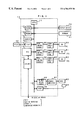
FIG. 1 is a functional block diagram showing essential elements of a CNC apparatus 10 for drivingly controlling an NC machine tool. In the present invention, a processor capable of operating in a low-electric-power consumption mode is used as a processor 11 for generally controlling the CNC apparatus 10. The processor 11 reads, through a bus 19, a system program stored in a ROM 12, and generally controls the CNC apparatus 10 according to the system program. A RAM 13 stores temporary calculation data, display data and a variety of data inputted by an operator through a keyboard 71. A CMOS memory 14 is backed up by a battery (not shown) and functions as a non-volatile memory which retains its memorized state even when the power for the CNC apparatus 10 is switched off. The CMOS memory 14 stores machining programs read through an interface 15 or inputted using a display device 70 and the keyboard 71. In the ROM 12, a variety of system programs are memorized in advance for performing processing in an edit mode necessary for creating and editing machining programs, and processing for automatic operation.
The interface 15 is for external devices connectable to the CNC apparatus 10. An external device 72 such as a floppy cassette adapter is connected to the interface 15. Through the external device 72, machining programs are read and also machining programs edited in the CNC apparatus 10 can be stored in a floppy cassette or the like.
A PC (programmable controller) 16 controls auxiliary devices of the machine tool, such as an actuator of a robot hand for changing tools in accordance with sequence programs stored in the CNC apparatus 10. Specifically, the PC 16 converts M-function, S-function and T-function commands specified in machining programs into signals suitable for the auxiliary device according to the sequence program to output them to the auxiliary device side through an I/O unit 17. Auxiliary devices such as various actuators operates in accordance with those output signals. The PC 16 further receives signals from various switches on an operating panel provided on the body of a machine tool and performs necessary processing on those signals to forward them to the processor 11. Particularly in relation to the present invention, a temperature sensor TS is provided in the vicinity of the processor 11 in the CNC apparatus 10 so that the processor 11 can detect a signal from the temperature sensor TS through the I/O unit 17 and the PC 16. A fan stop detecting sensor FS is also provided. A fan for cooling the CNC apparatus 10 is connected to the I/O unit 17 and the processor 11 outputs a drive command to the fan F and also capable of detecting a fan stop detection signal from the fan stop detecting sensor FS through the I/O unit 17 and the PC 16.
Axis control circuits 30 to 32 for feed axes X, Y, Z of the machine tool respectively receive a motion command for their axes, which is outputted from the processor 11 in each distribution period, and perform position and speed loop processing to output a torque command to their servo amplifiers 40 to 42. Receiving the torque command, the servo amplifiers 40 to 42 drive their servo motors 50 to 52 for their axes of the machine tool. In each of the servo motors 50 to 52 for the respective axes, a position detector and a speed detector are provided, and a position feedback signal and a speed feedback signal are fed back from each position detector and each speed detector to each axis control circuit 30 to 32. In FIG. 1, indication of feedback of each position signal and each speed signal is omitted, and an example of a machine tool having three feed axes is shown.
A spindle control circuit 60 receives a spindle rotation command for the machine tool and outputs a spindle speed signal to a spindle amplifier 61. Receiving the spindle speed signal, the spindle amplifier 61 makes a spindle motor 62 rotate at a commanded rotating speed. To the spindle motor 62, a position coder 63 is connected by a gear, a belt or the like. The position coder 63 outputs a feedback pulse in synchronism with the rotation of the spindle and the feedback pulse is read by the processor 11 through an interface 18.
The above described structure of the CNC apparatus is not different from the structure of conventional CNC apparatus. The present invention differs from the conventional method in controlling the operation of the CNC apparatus when a stop of operation of a fan or a rise in temperature is detected.
The processor 11 of the CNC apparatus commands to drive the spindle motor and the servo motors 50 to 52 for the respective feed axes in accordance with an NC machining program stored in the CMOS memory 14 to thereby machine a workpiece. In a regular state, the processor 11 performs processing including calculation of a position of each axis, distribution of a motion command to each axis control circuit 30 to 32 for each axis, processing related to the PC, processing for display, memory check for program protection under interruption control in a predetermined period, as shown in FIG. 2a.
When the fan stop signal is outputted from the fan stop detecting sensor FS through the I/O unit 17 and the PC 16, or temperature in the CNC apparatus 10 detected by the temperature sensor TS reaches a predetermined value, the processor 11 stops driving of the servo motors 50 to 52 for the respective axes and the spindled motor 62, and transfers to processing in a low-electric-power consumption mode, as shown in FIG. 2b.
Specifically, since the driving of the servo motors 50 to 52 and the spindle motor 62 is stopped, processing related to the axes control such as calculation of a position of each axis, distribution of a motion quantity to each axis, etc. is not necessary, and therefore not performed. The memory check is not performed, either. Only minimum processing necessary resuming control operation is performed. First, in consideration that an operator may perform some operation in order to take some measure, the processor 11 performs processing related to the PC and processing for display which are necessary for keeping a man/machine interface effective, in the same way as in the regular mode. Thus, dialogue between the CNC apparatus 10 and the operator is made possible. Then, the processor 11 transfers to a low-electric-power consumption mode. In the low-electric-power consumption mode, the processors 11 does not perform processing which is not required for the present state, such as introduction of a clock to a calculation and performing of the calculation. Instead, the processor 11 performs minimum processing required for keeping the CPU in an operating state, such as clock processing, processing for keeping coherence between a cache memory and a main memory. When a fixed time period passes, the processor 11 transfers to a normal mode in which is performs processing related to the PC and processing for display, again. When a further fixed time period passes after the processor 11 has transferred to the normal mode, the processor 11 transfers to the low-electric-power consumption mode, in which it performs only the above mentioned processing. Referring to FIG. 2b, at each point of time ta, each time the fixed time period elapses, the processor 11 transfers to the normal mode, and at every point of time tb, each time a predetermined time elapses from each point of time ta, the processor 11 transfers to the low-electric-power consumption mode. The processor 11 repeats such switching of the modes. While this switching of the modes is repeated, since the processor 11 does not perform processing related to the axes control and only performs minimum processing required for resuming control operation, heating of the processor 11 is reduced to prevent thermal runaway and thermal destruction of the processor 11.
FIG. 3 is a flowchart showing the above described processing to be performed by the processor 11.
The processor 11 determines whether or not the fan stop signal is inputted and whether or not the detected temperature is equal to or higher than a predetermined value (Step S1). If the fan stop signal is not inputted and the temperature detected by the temperature sensor is lower than the predetermined value, the processor 11 calculates positions of the respective axes according to the NC machining program (Step S2), and outputs distributed data of a motion command to the axis control circuits 30 to 32 for the respective axes (Step S3).
Then, the processor 11 performs processing of information cooperatively with a processor of the PC 16, displays necessary information on the display device 70 (Steps S4, S5), and performs memory check (Step S6). Thus, the processor 11 ends the processing of the present processing cycle.
If the fan stop signal is detected or it is determined that the detected temperature reaches a predetermined value at Step S1, the processor 11 performs only the aforementioned processing related to the PC and the processing for display (Steps S7, S8), to terminate processing of the normal mode, and performs processing in the lowe-lectric-power consumption mode such as clock processing, processing for keeping coherence between the cache memory and the main memory (not illustrated). Thus, the processing to be performed by the processor 11 is little, so that a rise in temperature of the processor 11 is reduced.
In the above embodiment, in order to protect the processor 11, when the fan stops or the detected temperature reaches a predetermined value, driving of the motors is stopped and processing related to the axes control is omitted to thereby reduce processing to be performed by the processor 11 and prevent heat generation thereof. Next, a second embodiment in which the processor 11 is protected without stopping the driving of the motors will be described.
In this second embodiment, first, there are set: a threshold value T1 for defining an upper limit of temperature below which the normal operation is allowed; a threshold value T2 higher than the threshold value T1, for defining an upper limit of temperature below which a first operation stage in the low-electric-power consumption mode is allowed; a rate of dropping the operating speed, i.e., the feeding speed of the axes in that first stage (override value) n1[%]; a limit temperature T3 higher than the threshold value T2 for the first operation stage in low-electric-power consumption mode, for defining a value below which a second operation stage in the low-electric-power consumption mode is allowed and at or above which the operation is stopped; a rate of dropping an operating speed in the second operation stage in the low-electric-power consumption mode (override value) n2[%]; an acceleration/deceleration time constant for the normal operation; and an acceleration/deceleration time constant for the first and second stages in the low-electric-power consumption mode.
The values T1, T2, T3 are set as T1<T2<T3, and the values n1, n2 are set as n2<n1. The acceleration/deceleration time constant for the first and second stages in the low-electric-power consumption mode is larger than that in the normal operation mode to make the acceleration/deceleration period longer.
Based on the above, the processor 11 performs processing shown in FIG. 4 in each predetermined processing cycle.
The processor 11 determines whether or not the temperature Tr in the CNC control device 10 detected by the temperature sensor is lower than the set threshold T1 below which the normal operation is allowed (Step A1). If it is lower than the threshold T1, the processor 11 performs the normal operation at a normal speed (Step A2). In accordance with the NC machining program, the processor distributes motion commands to the respective axes and drives the servo motors 50 to 52 for the respective axes with a feeding speed designated in the NC machining program. The acceleration/deceleration time constant used in this case is the set value for the normal operation.
In Step A1, if the detected temperature Tr is equal to the threshold T1 or higher, the processor 11 proceeds to Step A3, where it is determined whether or not the detected temperature Tr is lower than the set threshold T2 defining an upper limit of temperature for the first stage in the low-electric-power consumption mode. If it is lower than the threshold value T2, a feeding speed in this case is set to a value obtained by multiplying the feeding speed designated in the NC machining program by the override value n1 set for the first stage in the low-electric-power consumption mode (Step A4). The processor 11 further turns off the back light of the display device 70 (or instead, reduces luminous energy of the back light to darken it so as to reduce heat generation), and changes the acceleration/deceleration time constant to the value set for the low electric power consumption mode (Step A5).
As a result, the feeding speed drops, so that calculation for obtaining motion quantities to be supplied to the respective axes in each distribution cycle becomes simpler, and thus, time required for processing related to the axes is smaller and quantity of heat generated by the processor 11 is reduced. Further, since the back light of the display device 70 is turned off and heat generation is reduced correspondingly, a rise in temperature of the CNC apparatus 10 is suppressed. Furthermore, when the acceleration/deceleration time constant is made larger, the value of current flowing through the servo motors 50 to 52 for the feed axes at the time of acceleration/deceleration is reduced. Accordingly, the heat generation of the motors is reduced, a rise in temperature of the entire system of the CNC apparatus 10 including the processor 11 is reduced.
If the detected temperature Tr is higher than the set threshold T1 and T2 but lower than the set limit temperature T3 (Step A6), the feeding speed in this case is set to a value obtained by multiplying the feeding speed designated in the program by the override value n2 set for the second stage in the low electrical power consumption mode to thereby drops the actual feeding speed steeply (Step A7). Also in this case, the processor 11 further turns off the back light and changes the acceleration/deceleration time constant to the value set for the low-electric-power consumption mode (Step A5). Thus, a rise in temperature in the CNC 10 and in the processor 11 is further reduced.
If the temperature further rises and the detected temperature Tr reaches the limit temperature T3 or higher, the system is stopped (Step A8) since there is a risk that thermal runaway or thermal destruction of the processor 11 would happen. In this case, the operation of the CNC apparatus 10 is stopped with the temperature rising slowly, since the feeding speed, that is, the operating speed is already dropped before the stop of the operation. Thus, even when the operation of the CNC apparatus is stopped, the temperature of the processor 11 can not rise steeply, so that thermal runaway of the processor 11 is prevented.
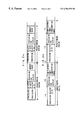
A rise in temperature in the second embodiment will be explained referring to FIG. 5. In FIG. 5, the abscissa represents time and the ordinate represents detected temperature Tr. FIG. 5 shows an example in which the feeding speed designated in the program is 10 m/min, the override values n1 and n2 for the first and second stages in the low- electric-power consumption mode are 75% and 50%, respectively.
While the fan operates, heat generation by the processor 11, etc. and cooling by the fan is equilibrated, so that the temperature in the CNC apparatus is constant. It is assumed that the operation of the fan stops at point of time t0, the equilibrium is lost and the temperature in the CNC apparatus 10 rises steeply. If the detected temperature Tr reaches the set threshold T1 at point of time t1, the feeding speed is reduced to 75% of the speed designated in the program (i.e. 7.5 m/min) as described above, the back light is turned off and the acceleration/deceleration time constant is made larger. As a result, a rise in temperature is made slow.
Then, if the detected temperature Tr reaches, at time point t2, the set threshold T2 for the second stage in the low-electric-power consumption mode, the feeding speed is further reduced to 50% of the speed specified in the program, i.e., 5 m/min. As a result, the heat generation is reduced, and the rise in temperature in the CNC apparatus is further reduced. In the example of FIG. 5, the heat generation and the radiation by natural ventilation are equilibrated at this stage, so that the rise in temperature stops and the equilibrium is maintained.
In the present invention, the processor performs only minimum required processing in each processing cycle and operates in the lowe-lectric-power consumption mode for the rest of time, when operation of the cooling fan of the controller stops or when the temperature in the controller rises. Therefore, heat generation of the processor is reduced to suppress the rise in temperature. Further, since the above-mentioned minimum required processing is related to a man/machine interface, the operation can be easily restored and resumed.
Furthermore, an operating speed of a machine, a robot, etc. which is controlled by the controller is reduced as a temperature in the controller rises, so that a load on the processor is reduced to suppress the heat generation and the rise in temperature of the processor. Thus, the operation of the machine, the robot and the like can be continued without stopping the operation of the controller.

Claims (8)

What is claimed is:
1. A method of operating a controller using a processor for controlling an industrial machine having axes and at least one motor for the axes, said processor performing a plurality of processings in every predetermined period and being capable of operating in a low-electric power consumption mode, said method comprising:
detecting an operating state of a cooling fan for cooling the interior of said controller;
detecting temperature inside said controller;
making the processor perform only minimum or limited processing required for resuming control of the axes in said plurality of processings to be regularly performed by the processor in every predetermined period and operate in a low-electric power consumption mode in a time period except the time period for performing said minimum or limited processing, when a stop of said cooling fan is detected or the temperature is detected to be higher than a first set value; and
making the processor stop driving the at least one motor and omit processing related to the control of the axes, when a stop of the cooling fan is detected or the temperature is detected to be higher than a second set value.
2. A method of operating a controller using a processor for controlling an industrial machine, comprising:
detecting a temperature inside the controller; and
controlling the industrial machine by changing an operating speed of the industrial machine depending on the temperature detected to reduce a rise in temperature in said controller.
3. A method of operating a controller for controlling an industrial machine according to claim 2,
wherein said controller has a display device with a back light, and wherein said controlling includes reducing luminous energy of said back light or turning off said back light depending on the temperature detected.
4. A method of operating a controller according to claim 2, wherein said controller controls a motor of the industrial machine, changing an acceleration/deceleration period for said motor depending on the temperature detected.
5. A method of controlling an industrial machine having at least one motor, using a controller having a processor, comprising:
detecting a temperature inside the controller; and
controlling the industrial machine by changing operation of the at least one motor depending on the temperature detected to reduce a rise in temperature in the controller.
6. A method according to claim 5, wherein the industrial machine has at least one axis, and wherein said method further comprises:
detecting an operating state of a cooling unit for cooling the interior of the controller; and
omitting processing related to controlling movement related to the at least one axis, when operation of the cooling unit is detected to have stopped or the temperature detected is higher than a set value.
7. A method according to claim 6, wherein the cooling unit includes a fan.
8. A method according to claim 6, wherein said controlling includes stopping the at least one motor to stop the movement related to the at least one axis when operation of the cooling unit is detected to have stopped or the temperature detected is higher than a set value.
US09/155,827 1997-02-06 1998-02-06 Method of operation controller having processor for controlling industrial machine Expired - Lifetime US6704875B1 (en)

Applications Claiming Priority (3)

Application Number Priority Date Filing Date Title
JP9-36944 1997-02-06
JP03694497A JP3168255B2 (en) 1997-02-06 1997-02-06 Operating method of a control device having a processor for driving and controlling a machine or a robot
PCT/JP1998/000510 WO1998035273A1 (en) 1997-02-06 1998-02-06 Method for operating controller for controlling industrial machine provided with processor

Publications (1)

Publication Number Publication Date
US6704875B1 true US6704875B1 (en) 2004-03-09

Family

ID=12483873

Family Applications (1)

Application Number Title Priority Date Filing Date
US09/155,827 Expired - Lifetime US6704875B1 (en) 1997-02-06 1998-02-06 Method of operation controller having processor for controlling industrial machine

Country Status (5)

Country Link
US (1) US6704875B1 (en)
EP (1) EP0909997B1 (en)
JP (1) JP3168255B2 (en)
DE (1) DE69841582D1 (en)
WO (1) WO1998035273A1 (en)

Cited By (14)

* Cited by examiner, † Cited by third party
Publication number Priority date Publication date Assignee Title
US20040203337A1 (en) * 2002-09-05 2004-10-14 Xytrans, Inc. Low cost VSAT MMIC transceiver with automatic power control
US20050080949A1 (en) * 2003-10-14 2005-04-14 Vu Mieu V. Method and system for direct access to a non-memory mapped device memory
US20050131584A1 (en) * 2003-12-12 2005-06-16 Octigabay Systems Corporation Methods and apparatus for replacing cooling systems in operating computers
US20050289360A1 (en) * 2004-06-01 2005-12-29 Rajesh Banginwar System to manage display power consumption
US20080091394A1 (en) * 2006-09-15 2008-04-17 Deckel Maho Pfronten Gmbh Device and method for simulating a sequence for machining a workpiece on a machine tool
US20080112571A1 (en) * 2006-11-09 2008-05-15 Thomas Michael Bradicich Noise control in proximity to a computer system
US20090063876A1 (en) * 2007-09-03 2009-03-05 Seiko Epson Corporation Information processing apparatus and semiconductor integrated circuit
US20090168834A1 (en) * 2007-12-27 2009-07-02 Hon Hai Precision Industry Co., Ltd. Apparatus and method for testing temperature
US20110154069A1 (en) * 2009-12-23 2011-06-23 Edward Costales Dynamic power state determination
US20130018484A1 (en) * 2007-11-13 2013-01-17 Schultz Ronald E Industrial Controller Using Shared Memory Multicore Architecture
US9809949B2 (en) 2014-04-25 2017-11-07 Harnischfeger Technologies, Inc. Controlling crowd runaway of an industrial machine
US10808382B2 (en) 2016-11-09 2020-10-20 Joy Global Surface Mining Inc Systems and methods of preventing a run-away state in an industrial machine
US20220137587A1 (en) * 2019-02-15 2022-05-05 Siemens Aktiengesellschaft Method for operating a numerically controlled production machine, and corresponding numerical control
US11553619B2 (en) * 2018-11-28 2023-01-10 Fanuc Corporation Control device and control method

Families Citing this family (3)

* Cited by examiner, † Cited by third party
Publication number Priority date Publication date Assignee Title
GB2411475B (en) * 2004-02-24 2006-10-25 Elliott Ind Ltd Position detecting system
JP4462059B2 (en) * 2005-02-14 2010-05-12 ブラザー工業株式会社 Controller temperature diagnosis device and motor temperature diagnosis device
DE102010001518A1 (en) * 2010-02-02 2011-08-04 DECKEL MAHO Pfronten GmbH, 87459 Device for controlling operating functions of a machine tool

Citations (27)

* Cited by examiner, † Cited by third party
Publication number Priority date Publication date Assignee Title
US3626385A (en) * 1969-12-30 1971-12-07 Ibm Time-shared numerical control system
JPS5441516A (en) 1977-09-08 1979-04-02 Taiho Kensetsu Kk Method of hardening soft ground
US4698655A (en) * 1983-09-23 1987-10-06 Motorola, Inc. Overvoltage and overtemperature protection circuit
JPS6420990A (en) 1987-07-13 1989-01-24 Matsushita Electric Ind Co Ltd Controller for industrial robot
US4907117A (en) * 1988-09-08 1990-03-06 National Semiconductor Corporation Integrated circuit thermal limit
JPH03107711A (en) 1989-09-21 1991-05-08 Mitsubishi Motors Corp Road surface measuring method
JPH03163603A (en) 1989-11-21 1991-07-15 Okuma Mach Works Ltd Numerical controller
JPH03294904A (en) 1990-04-12 1991-12-26 Amada Metrecs Co Ltd Temperature managing device of numerical control panel
JPH0457107A (en) 1990-06-27 1992-02-24 Hitachi Ltd Controller for robot
JPH0495109A (en) 1990-08-07 1992-03-27 Fuji Electric Co Ltd Device for countermeasure against heat generation of electronic apparatus
JPH04281424A (en) 1991-03-08 1992-10-07 Mitsubishi Electric Corp Back light device for liquid crystal display plate
JPH05150818A (en) 1991-06-28 1993-06-18 Hitachi Seiki Co Ltd Method and device or diagnosing fault of numerical control machine tool
US5249741A (en) * 1992-05-04 1993-10-05 International Business Machines Corporation Automatic fan speed control
JPH05297993A (en) 1992-04-16 1993-11-12 Dia Semikon Syst Kk Drive controller for microprocessor
JPH05303417A (en) 1992-04-24 1993-11-16 Yaskawa Electric Corp Control device for industrial robot
JPH075425A (en) 1993-06-14 1995-01-10 Mitsubishi Electric Corp Motor controller
US5448143A (en) * 1993-11-17 1995-09-05 Dell Usa, L.P. Sensor for monitoring fan operation in a PC or PC based system
JPH07311634A (en) 1994-05-18 1995-11-28 Fujitsu Ltd Power source controller
US5513361A (en) * 1994-07-25 1996-04-30 Intel Corporation Method and apparatus for reducing power consumption of a fan in a computer system
US5534854A (en) * 1995-07-10 1996-07-09 Bradbury; Rod J. Fan failure alert for electronic equipment
US5631852A (en) * 1995-05-22 1997-05-20 Eteq Microsystems, Inc. Smart cooling security system
JPH09179623A (en) 1995-12-22 1997-07-11 Makino Milling Mach Co Ltd Method and device for controlling mechanical device by numerical control
US5726874A (en) * 1996-11-13 1998-03-10 Liang; Charles Power supply having a dual air flow control for reducing heat buildup
US5835885A (en) * 1997-06-05 1998-11-10 Giga-Byte Technology Co., Ltd. Over temperature protection method and device for a central processing unit
US5848282A (en) * 1996-01-26 1998-12-08 Samsung Electronics Co., Ltd. Computer system with a control funtion of rotation speed of a cooling fan for a microprocessor chip therein and a method of controlling the cooling fan
US5977733A (en) * 1998-12-08 1999-11-02 Shin Jiuh Corporation Fan control device with breakdown warning capability
US6065930A (en) * 1997-07-15 2000-05-23 Fujitsu Limited Cooling control apparatus

Family Cites Families (4)

* Cited by examiner, † Cited by third party
Publication number Priority date Publication date Assignee Title
JPS5744794Y2 (en) * 1977-08-30 1982-10-02
EP0269373A3 (en) * 1986-11-20 1988-08-17 Unimation Inc. Multiaxis robot control having protection system with energy and backup velocity monitoring
JP2714451B2 (en) * 1989-08-23 1998-02-16 住友ベークライト株式会社 Epoxy resin composition
US5483102A (en) * 1994-05-12 1996-01-09 Intel Corporation Employing on die temperature sensors and fan-heatsink failure signals to control power dissipation

Patent Citations (27)

* Cited by examiner, † Cited by third party
Publication number Priority date Publication date Assignee Title
US3626385A (en) * 1969-12-30 1971-12-07 Ibm Time-shared numerical control system
JPS5441516A (en) 1977-09-08 1979-04-02 Taiho Kensetsu Kk Method of hardening soft ground
US4698655A (en) * 1983-09-23 1987-10-06 Motorola, Inc. Overvoltage and overtemperature protection circuit
JPS6420990A (en) 1987-07-13 1989-01-24 Matsushita Electric Ind Co Ltd Controller for industrial robot
US4907117A (en) * 1988-09-08 1990-03-06 National Semiconductor Corporation Integrated circuit thermal limit
JPH03107711A (en) 1989-09-21 1991-05-08 Mitsubishi Motors Corp Road surface measuring method
JPH03163603A (en) 1989-11-21 1991-07-15 Okuma Mach Works Ltd Numerical controller
JPH03294904A (en) 1990-04-12 1991-12-26 Amada Metrecs Co Ltd Temperature managing device of numerical control panel
JPH0457107A (en) 1990-06-27 1992-02-24 Hitachi Ltd Controller for robot
JPH0495109A (en) 1990-08-07 1992-03-27 Fuji Electric Co Ltd Device for countermeasure against heat generation of electronic apparatus
JPH04281424A (en) 1991-03-08 1992-10-07 Mitsubishi Electric Corp Back light device for liquid crystal display plate
JPH05150818A (en) 1991-06-28 1993-06-18 Hitachi Seiki Co Ltd Method and device or diagnosing fault of numerical control machine tool
JPH05297993A (en) 1992-04-16 1993-11-12 Dia Semikon Syst Kk Drive controller for microprocessor
JPH05303417A (en) 1992-04-24 1993-11-16 Yaskawa Electric Corp Control device for industrial robot
US5249741A (en) * 1992-05-04 1993-10-05 International Business Machines Corporation Automatic fan speed control
JPH075425A (en) 1993-06-14 1995-01-10 Mitsubishi Electric Corp Motor controller
US5448143A (en) * 1993-11-17 1995-09-05 Dell Usa, L.P. Sensor for monitoring fan operation in a PC or PC based system
JPH07311634A (en) 1994-05-18 1995-11-28 Fujitsu Ltd Power source controller
US5513361A (en) * 1994-07-25 1996-04-30 Intel Corporation Method and apparatus for reducing power consumption of a fan in a computer system
US5631852A (en) * 1995-05-22 1997-05-20 Eteq Microsystems, Inc. Smart cooling security system
US5534854A (en) * 1995-07-10 1996-07-09 Bradbury; Rod J. Fan failure alert for electronic equipment
JPH09179623A (en) 1995-12-22 1997-07-11 Makino Milling Mach Co Ltd Method and device for controlling mechanical device by numerical control
US5848282A (en) * 1996-01-26 1998-12-08 Samsung Electronics Co., Ltd. Computer system with a control funtion of rotation speed of a cooling fan for a microprocessor chip therein and a method of controlling the cooling fan
US5726874A (en) * 1996-11-13 1998-03-10 Liang; Charles Power supply having a dual air flow control for reducing heat buildup
US5835885A (en) * 1997-06-05 1998-11-10 Giga-Byte Technology Co., Ltd. Over temperature protection method and device for a central processing unit
US6065930A (en) * 1997-07-15 2000-05-23 Fujitsu Limited Cooling control apparatus
US5977733A (en) * 1998-12-08 1999-11-02 Shin Jiuh Corporation Fan control device with breakdown warning capability

Cited By (27)

* Cited by examiner, † Cited by third party
Publication number Priority date Publication date Assignee Title
US7076201B2 (en) * 2002-09-05 2006-07-11 Xytrans, Inc. Low cost VSAT MMIC transceiver with automatic power control
US20040203337A1 (en) * 2002-09-05 2004-10-14 Xytrans, Inc. Low cost VSAT MMIC transceiver with automatic power control
US7293153B2 (en) 2003-10-14 2007-11-06 Freescale Semiconductor, Inc. Method and system for direct access to a non-memory mapped device memory
WO2005038585A3 (en) * 2003-10-14 2007-01-25 Freescale Semiconductor Inc Method and system for direct access to a non-memory mapped device memory
US20050080949A1 (en) * 2003-10-14 2005-04-14 Vu Mieu V. Method and system for direct access to a non-memory mapped device memory
US7017059B2 (en) * 2003-12-12 2006-03-21 Cray Canada Inc. Methods and apparatus for replacing cooling systems in operating computers
US20060122740A1 (en) * 2003-12-12 2006-06-08 Cray Canada Inc. Methods and apparatus for replacing cooling systems in operating computers
US20050131584A1 (en) * 2003-12-12 2005-06-16 Octigabay Systems Corporation Methods and apparatus for replacing cooling systems in operating computers
US7219247B2 (en) 2003-12-12 2007-05-15 Cray Canada Inc. Methods and apparatus for replacing cooling systems in operating computers
US20050289360A1 (en) * 2004-06-01 2005-12-29 Rajesh Banginwar System to manage display power consumption
US7570259B2 (en) * 2004-06-01 2009-08-04 Intel Corporation System to manage display power consumption
US20080091394A1 (en) * 2006-09-15 2008-04-17 Deckel Maho Pfronten Gmbh Device and method for simulating a sequence for machining a workpiece on a machine tool
US9360861B2 (en) * 2006-09-15 2016-06-07 Dmg Electronics Gmbh Device and method for simulating a sequence for machining a workpiece on a machine tool
US20080112571A1 (en) * 2006-11-09 2008-05-15 Thomas Michael Bradicich Noise control in proximity to a computer system
US20090063876A1 (en) * 2007-09-03 2009-03-05 Seiko Epson Corporation Information processing apparatus and semiconductor integrated circuit
US7996692B2 (en) * 2007-09-03 2011-08-09 Seiko Epson Corporation Information processing apparatus and semiconductor integrated circuit
US20130018484A1 (en) * 2007-11-13 2013-01-17 Schultz Ronald E Industrial Controller Using Shared Memory Multicore Architecture
US9092023B2 (en) * 2007-11-13 2015-07-28 Rockwell Automation Technologies, Inc. Industrial controller using shared memory multicore architecture
US7862231B2 (en) * 2007-12-27 2011-01-04 Foxnum Technology Co., Ltd. Apparatus and method for testing temperature
US20090168834A1 (en) * 2007-12-27 2009-07-02 Hon Hai Precision Industry Co., Ltd. Apparatus and method for testing temperature
US20110154069A1 (en) * 2009-12-23 2011-06-23 Edward Costales Dynamic power state determination
US8555091B2 (en) 2009-12-23 2013-10-08 Intel Corporation Dynamic power state determination of a graphics processing unit
US9809949B2 (en) 2014-04-25 2017-11-07 Harnischfeger Technologies, Inc. Controlling crowd runaway of an industrial machine
US10683633B2 (en) 2014-04-25 2020-06-16 Joy Global Surface Mining Inc Controlling crowd runaway of an industrial machine
US10808382B2 (en) 2016-11-09 2020-10-20 Joy Global Surface Mining Inc Systems and methods of preventing a run-away state in an industrial machine
US11553619B2 (en) * 2018-11-28 2023-01-10 Fanuc Corporation Control device and control method
US20220137587A1 (en) * 2019-02-15 2022-05-05 Siemens Aktiengesellschaft Method for operating a numerically controlled production machine, and corresponding numerical control

Also Published As

Publication number Publication date
EP0909997A1 (en) 1999-04-21
EP0909997B1 (en) 2010-03-31
DE69841582D1 (en) 2010-05-12
JP3168255B2 (en) 2001-05-21
JPH10222214A (en) 1998-08-21
EP0909997A4 (en) 2004-05-12
WO1998035273A1 (en) 1998-08-13

Similar Documents

Publication Publication Date Title
US6704875B1 (en) Method of operation controller having processor for controlling industrial machine
JP3363958B2 (en) Drilling method
JP3902710B2 (en) Method and apparatus for controlling machine tool by numerical control
JPH07132440A (en) Machining load monitoring system
EP0666138B1 (en) Tool breakage prevention system
WO1995004633A1 (en) Tool life estimation method
JPH11296213A (en) Machine device
US11402824B2 (en) Numerical controller
JP4025999B2 (en) Automatic machine control device
US5289367A (en) Numerical control apparatus using fuzzy control
US10120367B2 (en) Numerical controller performing repetitive machining
JPH0751999A (en) Tool breakage detecting method
US6397123B1 (en) Numerical control apparatus
JPH11327624A (en) Numerical controller with feed speed controlling function
JPH0751996A (en) Surplus load detecting method for cnc
US10564630B2 (en) Numerical controller
JPH0751997A (en) Machining load monitoring method
US11156986B2 (en) Machining program editing device
JP2880211B2 (en) Tool load monitoring control method
JPH10277887A (en) Motor controlling method applicable at failure in position sensor
JPH0751992A (en) Drilling work method
WO2023053343A9 (en) Control device
JPH06297296A (en) Numerical control device and automatic programming device
WO2023139763A1 (en) Control device
WO2023032164A1 (en) Numerical control system

Legal Events

Date Code Title Description
AS Assignment

Owner name: FANUC LTD., JAPAN

Free format text: ASSIGNMENT OF ASSIGNORS INTEREST;ASSIGNORS:KINOSHITA, JIRO;AOYAMA, KAZUNARI;OKAMURA, YUKIO;REEL/FRAME:009726/0447

Effective date: 19981001

STCF Information on status: patent grant

Free format text: PATENTED CASE

CC Certificate of correction
FEPP Fee payment procedure

Free format text: PAYER NUMBER DE-ASSIGNED (ORIGINAL EVENT CODE: RMPN); ENTITY STATUS OF PATENT OWNER: LARGE ENTITY

Free format text: PAYOR NUMBER ASSIGNED (ORIGINAL EVENT CODE: ASPN); ENTITY STATUS OF PATENT OWNER: LARGE ENTITY

FPAY Fee payment

Year of fee payment: 4

CC Certificate of correction
FEPP Fee payment procedure

Free format text: PAYER NUMBER DE-ASSIGNED (ORIGINAL EVENT CODE: RMPN); ENTITY STATUS OF PATENT OWNER: LARGE ENTITY

Free format text: PAYOR NUMBER ASSIGNED (ORIGINAL EVENT CODE: ASPN); ENTITY STATUS OF PATENT OWNER: LARGE ENTITY

FPAY Fee payment

Year of fee payment: 8

FPAY Fee payment

Year of fee payment: 12