US6731674B1 - Device and method for generating quasi-orthogonal code and spreading channel signals in mobile communication system - Google Patents

Device and method for generating quasi-orthogonal code and spreading channel signals in mobile communication system Download PDF

Info

Publication number
US6731674B1
US6731674B1 US09/405,333 US40533399A US6731674B1 US 6731674 B1 US6731674 B1 US 6731674B1 US 40533399 A US40533399 A US 40533399A US 6731674 B1 US6731674 B1 US 6731674B1
Authority
US
United States
Prior art keywords
orthogonal code
quasi
mask
orthogonal
sequences
Prior art date
Legal status (The legal status is an assumption and is not a legal conclusion. Google has not performed a legal analysis and makes no representation as to the accuracy of the status listed.)
Expired - Lifetime
Application number
US09/405,333
Inventor
Kyeong-Cheol Yang
Jae-Yoel Kim
Hee-Won Kang
Young-Ky Kim
Current Assignee (The listed assignees may be inaccurate. Google has not performed a legal analysis and makes no representation or warranty as to the accuracy of the list.)
Samsung Electronics Co Ltd
Original Assignee
Samsung Electronics Co Ltd
Priority date (The priority date is an assumption and is not a legal conclusion. Google has not performed a legal analysis and makes no representation as to the accuracy of the date listed.)
Filing date
Publication date
Application filed by Samsung Electronics Co Ltd filed Critical Samsung Electronics Co Ltd
Assigned to SAMSUNG ELECTRONICS CO., LTD. reassignment SAMSUNG ELECTRONICS CO., LTD. ASSIGNMENT OF ASSIGNORS INTEREST (SEE DOCUMENT FOR DETAILS). Assignors: KANG, HEE-WON, KIM, JAE-YOEL, KIM, YOUNG-KY, YANG, KYEONG-CHEOL
Application granted granted Critical
Publication of US6731674B1 publication Critical patent/US6731674B1/en
Anticipated expiration legal-status Critical
Expired - Lifetime legal-status Critical Current

Links

Images

Classifications

    • HELECTRICITY
    • H04ELECTRIC COMMUNICATION TECHNIQUE
    • H04JMULTIPLEX COMMUNICATION
    • H04J13/00Code division multiplex systems
    • H04J13/10Code generation
    • HELECTRICITY
    • H04ELECTRIC COMMUNICATION TECHNIQUE
    • H04JMULTIPLEX COMMUNICATION
    • H04J13/00Code division multiplex systems
    • H04J13/0007Code type
    • H04J13/004Orthogonal
    • H04J13/0048Walsh

Definitions

  • the present invention relates generally to a channel communication device and a method used in a CDMA communication system, and in particular, to a device and method for generating binary quasi-orthogonal codes and spreading channel signals using the generated binary quasi-orthogonal codes.
  • a CDMA (Code Division Multiple Access) mobile communication system performs channel separation using orthogonal codes in order to increase channel capacity.
  • Walsh orthogonal codes are typically used for the orthogonal codes.
  • a forward link specified by the IS-95/IS-95A standard separates the channels using the Walsh orthogonal codes.
  • FIG. 1 illustrates the IS-95/IS-95A forward link in which channels are separated by Walsh orthogonal codes.
  • BPSK Binary Phase Shift Keying
  • the number of available Walsh orthogonal codes is dependent on the employed modulation method and the minimum data rate.
  • future CDMA mobile communication systems will require a greater number of channels assigned to users in order to improve performance.
  • future CDMA mobile communication systems will employ traffic channels, pilot channels and control channels, thereby increasing channel capacity.
  • an object of the present invention to provide a device and method for generating quasi-orthogonal codes which have the least interference with Walsh orthogonal codes in a CDMA communication system using the Walsh orthogonal codes to perform channel spreading.
  • the method comprises generating an m-sequence, and specific left and right sequences having a good full correlation property with the m-sequence; column permuting the specific left and right sequences in a column permutation method used when converting the m-sequence to a Walsh orthogonal code, and connecting the left sequences to the right sequences to generate mask candidates; operating the mask candidates and Walsh orthogonal codes having the same length as the mask candidates to generate quasi-orthogonal code candidate families; and selecting a quasi-orthogonal code out of the generated quasi-orthogonal code candidate families, the selected quasi-orthogonal code satisfying a partial correlation property with the Walsh orthogonal codes, and selecting a mask related to generation of the selected quasi-orthogonal code.
  • FIG. 1 is a diagram illustrating channel separation using Walsh orthogonal codes in a conventional CDMA communication system
  • FIG. 2 is a diagram illustrating a partial correlation property between a Walsh orthogonal code and a quasi-orthogonal code, satisfying Condition 3 according to an embodiment of the present invention
  • FIG. 3 is a diagram illustrating a matrix Q for shifted sequences according to an embodiment of the present invention
  • FIG. 4 is a diagram illustrating a matrix Q′ for quasi-orthogonal code candidates added to Walsh orthogonal codes after performing column permutation for the matrix Q of FIG. 3 according to an embodiment of the present invention
  • FIG. 5 is a flow chart illustrating a procedure for generating binary quasi-orthogonal codes according to a first embodiment of the present invention
  • FIG. 6 is a diagram illustrating channel separation using Walsh orthogonal codes and quasi-orthogonal codes generated according to an embodiment of the present invention, in a CDMA communication system;
  • FIG. 7 is a bock diagram illustrating a channel transmitter using quasi-orthogonal codes generated according to an embodiment of the present invention, in a CDMA communication system
  • FIG. 8 is a block diagram illustrating a quasi-orthogonal code generator for the channel transmitter of FIG. 7 according to an embodiment of the present invention in a CDMA communication system;
  • FIG. 9 is a diagram illustrating a quasi-orthogonal code mask table in the quasi-orthogonal code generator of FIG. 8 according to an embodiment of the present invention, by way of example;
  • FIG. 10 is a diagram illustrating a Walsh orthogonal code table in the quasi-orthogonal code generator of FIG. 8 according to an embodiment of the present invention, by way of example;
  • FIG. 11 is a diagram illustrating a table for generating quasi-orthogonal codes in the quasi-orthogonal code generator of FIG. 8 according to another embodiment of the present invention.
  • FIG. 12 is a block diagram illustrating a channel transmitter for spreading channel signals using quasi-orthogonal codes and Walsh orthogonal codes in a CDMA communication system
  • FIG. 13 is a detailed block diagram illustrating a scheme for spreading channel signals transmitted using quasi-orthogonal codes in FIG. 12;
  • FIG. 14 is a detailed block diagram illustrating a scheme for spreading channel signals transmitted using quasi-orthogonal codes and Walsh orthogonal codes in FIG. 12 .
  • the present invention generates quasi-orthogonal codes, which will have limited interference with orthogonal codes, in order to increase the channel capacity or maximize a capacity of a single cell in a CDMA communication system.
  • Equation (1) W k (t) denotes the k-th sequence of a Walsh orthogonal code having length N (1 ⁇ k ⁇ N) and S i (t) denotes an i-th quasi-orthogonal code having length N (1 ⁇ i ⁇ X), where X denotes the number of quasi-orthogonal codes satisfying Conditions 1 to 3.
  • Condition 1 expressed by Equation (1) means that the full correlation between the k-th Walsh orthogonal code W k (t) (1 ⁇ k ⁇ N, 1 ⁇ t ⁇ N) and the i-th quasi-orthogonal code S i (t) (1 ⁇ i ⁇ X, 1 ⁇ t ⁇ N) should not exceed ⁇ min (N).
  • Condition 2 expressed by Equation (2) means that the full correlation between an i-th line and an i′-th line of a quasi-orthogonal code should not exceed ⁇ min (N).
  • Condition 3 expressed by Equation (3) means that a partial correlation should not exceed ⁇ m ⁇ ⁇ i ⁇ ⁇ n ⁇ ( N M ) ,
  • Condition 2 of Equation (2) represents a condition for a full correlation property between quasi-orthogonal codes.
  • Condition 3 of Equation (3) represents a partial correlation property between a Walsh orthogonal code and a quasi-orthogonal code, as shown in FIG. 2 .
  • M 2 m (0 ⁇ m ⁇ log 2 N).
  • Table 2 shows the relationship between the length N and the minimum correlation value ⁇ min (N).
  • Kerdock code families are generated as Family A sequences so as to generate binary quasi-orthogonal code families having the increased number of code families satisfying the above conditions.
  • Kerdock codes For formation, see A. R. Hammons, P. V. Kumar, A. R. Calderbank, N. J. A. Sloane, and P. Sole, “The Z4-linearity of Kerdock, Preparata, Goethals and related codes,”, IEEE Trans. Inform. Theory, vol.IT-40, pp. 301-319, Mar., 1994.
  • a binary Kerdock code of length 2 m ⁇ 2 is expressed as the sum of a sequence of length 2 m ⁇ 2 generated by repeating twice an m-sequence of length 2 m ⁇ 1 ⁇ 1, and a specific sequence of length 2 m ⁇ 2, wherein the specific sequence is generated by arranging left and right sequences each having length 2 m ⁇ 1 ⁇ 1.
  • a binary primitive polynomial f(x) of the (m-1)-th degree is selected to obtain a quasi-orthogonal code sequence of length 2 m . It is possible to construct a Galois Field GF(2 m ⁇ 1 ) using the characteristic polynomial f(x).
  • Kerdock codeword can be expressed as Equation (4) below by using a trace function in the Galois Field GF(2 m ⁇ 1 ).
  • Equation (4) ⁇ 1 ( ⁇ t ) is an m-sequence of length 2 m ⁇ 1 ⁇ 1, and a Walsh orthogonal code of length 2 m ⁇ 1 having symbols of “0” and “1” can be obtained by substituting “0” or ⁇ t (0 ⁇ i ⁇ 2 2 m ⁇ 1 ⁇ 2 ) for ⁇ and then column permuting it.
  • x 1 has a value of “0” and “1”, and it is possible to obtain (2 m ⁇ 1 ⁇ 1) sequences of length 2 m ⁇ 1 by inserting “0” at the head of the sequence Q ⁇ (t,x 1 ) of length 2 m ⁇ 1 ⁇ 1 for the respective x 1 and then substituting ⁇ t (0 ⁇ i ⁇ 2 2 m ⁇ 1 ⁇ 2) for ⁇ .
  • the matrix Q has (2 m ⁇ 1 ⁇ 1)*2 m rows and 2 m columns.
  • orthogonal codes of length 2 m and (2 m ⁇ 1 ⁇ 1) sequences satisfying Conditions 1 and 2; and it is possible to obtain (2 m ⁇ 1 ⁇ 1)*2 m quasi-orthogonal code candidates satisfying Conditions 1 and 2 by combining the above sequences as masks with Walsh orthogonal codes.
  • sequences satisfying Condition 3 will be extracted from the (2 m ⁇ 1 ⁇ 1)*2 m sequences.
  • FIG. 5 illustrates a procedure for generating quasi-orthogonal candidate sequences of length 2 m .
  • step 517 the leading 2 m ⁇ 1 part and the following 2 m ⁇ 1 part of the sequence generated in step 515 are independently column permuted by the column permutation function generated in step 513 . That is, in step 517 , new sequences are generated, which can be defined as: ⁇ [Equation 8] ⁇ [ e i ⁇ ( t )
  • step 519 quasi-orthogonal codes are arranged as shown in FIG. 4 using the sequences generated in the above process, in accordance with Equation (9) below.
  • a column permutation function for converting the m-sequence to a Walsh orthogonal code in accordance with Equation (8) is calculated using the m-sequence 1001011. Equation (8) implies that the m-sequence is converted into decimal numbers by grouping the m-sequence by three consecutive terms.
  • the first three terms 100 are converted to decimal number 4; the second three terms 001 are converted to decimal number 1; the third three terms 010 are converted to decimal number 2, the fourth three terms 101 are converted to decimal number 5; the fifth three terms 011 are converted to decimal number 3; the sixth three terms 111 are converted to decimal number 7; and the seventh three terms 110 are converted to decimal number 6.
  • step 515 “0” is added at the head of every left sequence determined in step 511 and then arranged; succeedingly, “0” is added at the head of every right sequence and then arranged.
  • d i (t) in accordance with S i (t)
  • d 0 (t) is the binary sequence S 0 (t)
  • step 517 the shifted arranged specific sequences of Table 3B are column permutated with the column permutation functions determined in step 513 .
  • Shown in Table 3C below are the binary sequences of Table 3B which are column permuted with the column permutation function determined in step 513 .
  • the left and right binary sequences are independently column shifted and arranged. Then, “0” is added to every left and right sequence to crease left and right sequences of length 8 . Thereafter, the left and right sequences are column permuted according to the column permutation function, respectively. The column permuted left and right sequences are connected to crease quasi-orthogonal code mask candidate functions of length 16.
  • the created binary quasi-orthogonal code mask candidates are added to Walsh orthogonal codes to verify whether Condition 3 is satisfied.
  • step 519 sequences satisfying Condition 3 are selected from the (2 m ⁇ 1 ⁇ 1)*2 m quasi-orthogonal code candidates, and the used quasi-orthogonal code mask candidate is selected as a quasi-orthogonal code mask. That is, after the process of step 517 , in step 519 , sequences satisfying Condition 3, are selected from the determined mask candidate families. With regard to the selecting method, every Walsh orthogonal code and a correlation for every length are determined to examine whether Condition 3 is satisfied, and accordingly selected as a mask when condition 3 is satisfied.
  • a partial correlation with every Walsh orthogonal code of length 64 is determined to examine whether the partial correlation exceeds 8.
  • the partial correlation exceeds 8 it is not selected as a mask; otherwise, when satisfied, a partial correlation is calculated again for partial length 32 with respect to the mask candidate. Then, it is examined whether the partial correlation value exceeds 8.
  • the partial correlation exceeds 8 it is not selected as a mask; otherwise, when satisfied, the same operation is performed for the next length.
  • a mask candidate having passed all of the above conditions is selected as a quasi-orthogonal code mask candidate satisfying Conditions 1 to 3.
  • Quasi-orthogonal code sequences generated using the process of FIG. 5 are determined by the mask function e i (t). That is, when the mask function e i (t) satisfy Conditions 1 to 3, it is, possible to obtain 2 m quasi-orthogonal codes. Therefore, if k masks satisfying Conditions 1 to 3 exist, it is possible to obtain k ⁇ 2 m quasi-orthogonal codes.
  • Table 4 shows the number of quasi-orthogonal codes according to the m-sequence.
  • the above quasi-orthogonal codes can be used for every link in the CDMA system using the Walsh orthogonal codes.
  • the quasi-orthogonal codes are used together with the orthogonal codes, the following three options can be considered.
  • One Walsh orthogonal code group and a binary quasi-orthogonal code group is selected to make two orthogonal sets, and the two groups both can provide a service at the variable data rate.
  • the quasi-orthogonal codes it is preferable to use the quasi-orthogonal codes according to the application, taking into consideration the above three options.
  • the modulating side exchanges a predetermined orthogonal code number with the demodulating side. Therefore, when the orthogonal codes and the quasi-orthogonal codes are used, it is necessary to exchange a predetermined orthogonal code number and a group number (i.e., an index i of the Q′ matrix e i (t) shown in FIG. 4 ).
  • the orthogonal code group is defined as a Group 0, and subsequently, the group numbers are redefined up to 2 m ⁇ 1.
  • Each element of the quasi-orthogonal code group is comprised of an orthogonal code number and a group number.
  • the group number indicates which e i (t) is selected in FIG. 4 .
  • a previously allocated orthogonal code number is used as a Walsh orthogonal code number and then, the allocated e i (t) is added to it for every length N.
  • FIG. 6 illustrates a channel separation method using the Walsh orthogonal codes and the quasi-orthogonal codes in an IS-95/IS-95A forward link to extend the channel capacity according to an embodiment of the present invention.
  • FIG. 7 illustrates a channel transmitter which separates channels using the quasi-orthogonal codes generated according to the present invention.
  • the mobile communication system shown in FIG. 7 constructs the channel bit streams in a method different from the IS-95 standard.
  • a signal converter (or demultiplexing & signal mapping part) 711 receiving a data bit stream X, separates the received data bit stream into odd-numbered bits and even-numbered bits to demultiplex the separated signals into I and Q signals, and then converts the separated I and Q signals by converting a signal “0” to “+1” and a signal “1” to “ ⁇ 1”.
  • a quasi-orthogonal code (QOC) generator 713 receiving quasi-orthogonal code mask index and a Walsh orthogonal code (WOC) mask index, generates a quasi-orthogonal code QOFk.
  • An orthogonal spreader 715 channel spreads the signals output from the signal converter 711 with the quasi-orthogonal code QOFk generated from the quasi-orthogonal code generator 713 .
  • a PN code generator 717 generates complex PN codes PNi and PNq.
  • a PN spreader 719 PN masks the orthogonally spread signals di and dq with PNi and PNq, respectively.
  • a baseband filter 721 filters the PN spread signals Xi and Xq into baseband signals.
  • a frequency shifter 723 up-converts the baseband filtered signals Xi and Xq to RF signals.
  • FIG. 7 illustrates one channel transmitter using the quasi-orthogonal code in a CDMA communication system
  • the transmitter includes N channels
  • the corresponding number of orthogonal spreaders should be provided which use the quasi-orthogonal codes.
  • binary input signals expressed as “0” and “1” are demultiplexed into I and Q signals by the signal converter 711 , and then converted in a such manner that a signal “0” is converted to “+1” and a signal “1” to “ ⁇ 1”.
  • the quasi-orthogonal code generator 713 then generates a quasi-orthogonal code QOFk according to the received quasi-orthogonal code mask index and Walsh orthogonal code mask index.
  • the orthogonal spreader 715 multiplies the signals output from the signal converter 711 by the quasi-orthogonal code QOFk to spread a transmission signal on the corresponding channel.
  • the quasi-orthogonal code generator 713 can be implemented using two different methods.
  • the quasi-orthogonal code generator 713 includes a memory shown in FIG. 11 to generate the quasi-orthogonal codes. That is, every quasi-orthogonal sequence is stored in the memory as shown in FIG. 11 to output the quasi-orthogonal sequence according to the quasi-orthogonal code mask index and the Walsh orthogonal code index. Further, the quasi-orthogonal code generator 713 stores all the available quasi-orthogonal sequences in the memory, and upon receipt of a quasi-orthogonal code index q and an orthogonal code index p, outputs (q*2 m +p)-th quasi-orthogonal sequence QOF q ⁇ 2 m +p . In FIG. 11, upper 2 m sequences are Walsh orthogonal code sequences, and the other sequences are quasi-orthogonal code sequences.
  • the quasi-orthogonal code generator 713 is implemented as shown in FIG. 8 .
  • the Walsh orthogonal code generator 813 storing Walsh orthogonal codes, outputs a Walsh orthogonal code W j according to a received Walsh orthogonal code index.
  • the Walsh orthogonal code generator 813 includes a Walsh orthogonal code table, which can be implemented as shown in FIG. 10 .
  • An adder 815 adds the quasi-orthogonal code mask e i output from the quasi-orthogonal code mask generator 811 and the Walsh orthogonal code W j output from the Walsh orthogonal code generator 813 to generate a quasi-orthogonal code QOFk.
  • a signal spread with the quasi-orthogonal code is applied to the PN spreader 719 .
  • the PN spreader 719 then spreads the signals di and dq output from the orthogonal spreader 715 with corresponding PN codes PNi and PNq, thereby performing PN masking.
  • the PN masked signals Xi and Xq are baseband filtered by the baseband filter 721 , and the baseband filtered signals are converted to RF signals by the frequency shifter 723 .
  • FIG. 12 illustrates a channel transmitter which uses a Walsh orthogonal code and a quasi-orthogonal code according to an embodiment of the present invention, in a CDMA communication system.
  • FIG. 12 shows an example in which when transmitting at least two transmission signals, the transmission signals of the respective channel transmitters are spread with unique quasi-orthogonal codes or unique Walsh orthogonal codes.
  • a first channel signal and a second channel signal can be signals on dedicated channels, or signals on a dedicated channel and a common channel.
  • the dedicated channel includes a fundamental channel, a supplemental channel and a dedicated control channel
  • the common channel includes a common control channel, a pilot channel, a sync channel and a paging channel.
  • the common channels use Walsh orthogonal codes
  • the dedicated channels use either the Walsh orthogonal codes or the quasi-orthogonal codes.
  • a first signal converter 1211 demultiplexes a received first channel beat stream to I and Q arms, and then converts the demultiplexed signals. That is, the first signal converter 1211 converts a signal “0” of the received first channel bit stream to “+1” and a signal “1” to “ ⁇ 1”, and provides the converted signals to an orthogonal code spreading and PN masking part 1219 .
  • a second signal converter 1213 demultiplexes a received second channel bit stream to I and Q arms, and then converts the demultiplexed signals. The second signal converter 1213 converts a signal “0” of the received second channel bit stream to “+1” and a signal “1” to “ ⁇ 1”, and provides the converted signals to the orthogonal code spreading and PN masking part 1219 .
  • An orthogonal code generator 1215 receiving a quasi-orthogonal code (QOC) mask index and a Walsh orthogonal code (WOC) index, generates a Walsh orthogonal code W j or a quasi-orthogonal code S i using the received indexes and provides the generated code to the orthogonal code spreading and PN masking part 1219 .
  • the number of orthogonal code generators 1215 should equal the number of the channel transmitters. For example, in FIG. 12, to separately provide orthogonal codes for the first channel and the second channel, there are required two orthogonal code generators.
  • the orthogonal code generator 1215 should be able to generate quasi-orthogonal codes and Walsh orthogonal codes according to the quasi-orthogonal code mask index and the Walsh orthogonal code index designated by an upper processor, as shown in FIG. 8 .
  • a PN code generator 1217 generates real and imaginary PN codes PNi and PNq and provides them to the orthogonal code spreading and PN masking part 1219 .
  • the orthogonal code spreading and PN masking part 1219 multiplies outputs of the first and second signal converters 1211 and 1213 by associated unique Walsh orthogonal codes Wj or quasi-orthogonal codes Si to spread the input signals, and again multiplies the spread signals by the PN codes PNi and PNq to generate PN masked signals Xi and Xq.
  • a baseband filter 1221 filters the signals Xi and Xq output from the orthogonal code spreading and PN masking part 1219 to baseband signals.
  • a frequency shifter 1223 frequency-shifts the signals output from the baseband filter 1221 to RF signals.
  • the orthogonal code spreading and PN masking part 1219 can be implemented in various configurations.
  • FIG. 13 illustrates an orthogonal code spreading and PN masking part implemented by a complex multiplier 1319 for complex PN masking, which uses a quasi-orthogonal code Si for the first channel and a Walsh orthogonal code W i for the second channel.
  • the complex multiplier 1319 can also be equally applied to the case where the quasi-orthogonal codes S i are used for both the first and second channels to perform complex PN masking.
  • FIGS. 13 and 14 illustrates an orthogonal code spreading and PN masking part, which employs non-complex PN masking and uses a Walsh orthogonal code W i for the first channel and a quasi-orthogonal code S i for the second channel.
  • W i Walsh orthogonal code
  • S i quasi-orthogonal code
  • FIGS. 13 and 14 the number of channel spreaders and orthogonal code generators provided as equal the number of channels. Further in FIG. 13, there is required only one complex multiplier.
  • a first spreader 1311 receiving a first channel signal, multiplies the received first channel signal by a quasi-orthogonal code S i to output spread signals di1 and dq1.
  • a second spreader 1313 receiving a second channel signal, multiplies the received second channel signal by a Walsh orthogonal code W i to output spread signals di2 and dq2.
  • a repeater 1317 repeats the PN codes PNi and PNq output from the PN code generator 1217 at predetermined times.
  • the complex multiplier 1319 adds the signal di1 to the signal di2 and the signal dq1 to dq2, output from the first and second spreaders 1311 and 1313 ; and complex multiplies the added signals di1+di2 and dq1+dq2 by the PN codes PNi and PNq output from the repeater 1317 , respectively, to generate PN masked signals Xi and Xq.
  • the complex multiplier 1319 performs complex PN masking by performing the complex operation shown in FIG. 13 .
  • FIG. 14 illustrates the orthogonal code spreading and PN masking part 1219 , wherein the Walsh orthogonal code W i is used for the first channel and the quasi-orthogonal code S i is used for the second channel, and non-complex PN masking is employed.
  • a first spreader 1411 receiving a first channel signal multiplies the received first channel signal by a Walsh orthogonal code W i to output spread signals di1 and dq1.
  • a second spreader 1413 receiving a second channel signal multiplies the received second channel signal by a quasi-orthogonal signal S i to output spread signals di2 and dq2.
  • An adder 1415 adds the spread signal di1 output from the first spreader 1411 to the spread signal di2 output from the second spreader 1413 to generate a signal di1+di2.
  • An adder 1417 adds the spread signal dq1 output from the first spreader 1411 to the spread signal dq2 output from the second spreader 1413 to generate a signal dq1+dq2.
  • a repeater 1421 repeats the PN codes PNi and PNq output from the PN code generator 1217 at predetermined times.
  • a multiplier 1423 multiplies the spread signal di1+di2 output from the adder 1415 by the PN code PNi output from the repeater 1421 to generate a masked signal Xi.
  • a multiplier 1425 multiplies the spread signal dq1+dq2 output from the adder 1417 by the PN code PNq to generate a masked signal Xq.
  • the Walsh orthogonal code W i assigned to the first channel should be different from the quasi-orthogonal code S i assigned to the second channel.
  • the orthogonal code spreading and PN masking part 1219 is implemented in this manner, it is possible to acquire accurate arrival time synchronization between the first channel and the second channel, thereby removing mutual interference between them.
  • the embodiment can generate quasi-orthogonal codes having the least interference with Walsh orthogonal codes. Further, in a mobile communication system which separates channels using the Walsh orthogonal codes, it is possible to increase channel capacity by using the quasi-orthogonal codes regardless of the limitation on the Walsh orthogonal codes.

Abstract

A device and method for generating a binary quasi-orthogonal code in a CDMA communication system. The method comprises generating an m-sequence, and specific left and right sequences having a good full correlation property with the m-sequence; column permuting the specific left and right sequences in a column permutation method used when converting the m-sequence to a Walsh orthogonal code, and connecting the left sequences to the right sequences to generate mask candidates; operating the mask candidates and Walsh orthogonal codes having the same length as the mask candidates to generate quasi-orthogonal code candidate families; and selecting a quasi-orthogonal code out of the generated quasi-orthogonal code candidate families, the selected quasi-orthogonal code satisfying a partial correlation property with the Walsh orthogonal codes, and selecting a mask related to generation of the selected quasi-orthogonal code.

Description

BACKGROUND OF THE INVENTION
1. Field of the Invention
The present invention relates generally to a channel communication device and a method used in a CDMA communication system, and in particular, to a device and method for generating binary quasi-orthogonal codes and spreading channel signals using the generated binary quasi-orthogonal codes.
2. Description of the Related Art
In general, a CDMA (Code Division Multiple Access) mobile communication system performs channel separation using orthogonal codes in order to increase channel capacity. Walsh orthogonal codes are typically used for the orthogonal codes. For example, a forward link specified by the IS-95/IS-95A standard separates the channels using the Walsh orthogonal codes.
FIG. 1 illustrates the IS-95/IS-95A forward link in which channels are separated by Walsh orthogonal codes. Referring to FIG. 1, channels are separated by unique Walsh orthogonal codes Wi (where i=0 to 63), respectively. The IS-95/IS-95A forward link uses a coding rate R=½ convolutional codes for channel coding, employs BPSK (Binary Phase Shift Keying) modulation for spreading the Walsh orthogonal codes, and has a bandwidth of 1.2288 MHz. Accordingly, the number of available channels is 1.2288 MHz/(9.6 KHz*2)=64. That is, the IS-95/IS-95A forward link can separate 64 channels using the Walsh orthogonal codes.
Therefore, the number of available Walsh orthogonal codes is dependent on the employed modulation method and the minimum data rate. However, future CDMA mobile communication systems will require a greater number of channels assigned to users in order to improve performance. To this end, future CDMA mobile communication systems will employ traffic channels, pilot channels and control channels, thereby increasing channel capacity.
However, there are a limited number of available orthogonal codes available for use. This limitation will restrict the increase in channel capacity. To overcome this disadvantage, it is desirable to generate quasi-orthogonal codes, which will limit interference with the orthogonal codes and a variable data rate.
SUMMARY OF THE INVENTION
It is, therefore, an object of the present invention to provide a device and method for generating quasi-orthogonal codes which have the least interference with Walsh orthogonal codes in a CDMA communication system using the Walsh orthogonal codes to perform channel spreading.
It is another object of the present invention to provide a device and method for generating binary quasi-orthogonal codes having excellent full correlation and partial correlation with Walsh orthogonal codes in a CDMA communication system.
It is further another object of the present invention to provide a device and method for spreading channel signals using quasi-orthogonal codes limiting interference with orthogonal codes in a CDMA communication system.
It is still another object of the present invention to provide a channel transmission device and method for spreading channel signals selectively using Walsh orthogonal codes and binary quasi-orthogonal codes in a CDMA communication system.
To achieve the above objects, there is provided a method for generating a binary quasi-orthogonal code in a CDMA communication system. The method comprises generating an m-sequence, and specific left and right sequences having a good full correlation property with the m-sequence; column permuting the specific left and right sequences in a column permutation method used when converting the m-sequence to a Walsh orthogonal code, and connecting the left sequences to the right sequences to generate mask candidates; operating the mask candidates and Walsh orthogonal codes having the same length as the mask candidates to generate quasi-orthogonal code candidate families; and selecting a quasi-orthogonal code out of the generated quasi-orthogonal code candidate families, the selected quasi-orthogonal code satisfying a partial correlation property with the Walsh orthogonal codes, and selecting a mask related to generation of the selected quasi-orthogonal code.
BRIEF DESCRIPTION OF THE DRAWINGS
The above and other objects, features and advantages of the present invention will become more apparent from the following detailed description when taken in conjunction with the accompanying drawings in which:
FIG. 1 is a diagram illustrating channel separation using Walsh orthogonal codes in a conventional CDMA communication system;
FIG. 2 is a diagram illustrating a partial correlation property between a Walsh orthogonal code and a quasi-orthogonal code, satisfying Condition 3 according to an embodiment of the present invention;
FIG. 3 is a diagram illustrating a matrix Q for shifted sequences according to an embodiment of the present invention;
FIG. 4 is a diagram illustrating a matrix Q′ for quasi-orthogonal code candidates added to Walsh orthogonal codes after performing column permutation for the matrix Q of FIG. 3 according to an embodiment of the present invention;
FIG. 5 is a flow chart illustrating a procedure for generating binary quasi-orthogonal codes according to a first embodiment of the present invention;
FIG. 6 is a diagram illustrating channel separation using Walsh orthogonal codes and quasi-orthogonal codes generated according to an embodiment of the present invention, in a CDMA communication system;
FIG. 7 is a bock diagram illustrating a channel transmitter using quasi-orthogonal codes generated according to an embodiment of the present invention, in a CDMA communication system;
FIG. 8 is a block diagram illustrating a quasi-orthogonal code generator for the channel transmitter of FIG. 7 according to an embodiment of the present invention in a CDMA communication system;
FIG. 9 is a diagram illustrating a quasi-orthogonal code mask table in the quasi-orthogonal code generator of FIG. 8 according to an embodiment of the present invention, by way of example;
FIG. 10 is a diagram illustrating a Walsh orthogonal code table in the quasi-orthogonal code generator of FIG. 8 according to an embodiment of the present invention, by way of example;
FIG. 11 is a diagram illustrating a table for generating quasi-orthogonal codes in the quasi-orthogonal code generator of FIG. 8 according to another embodiment of the present invention;
FIG. 12 is a block diagram illustrating a channel transmitter for spreading channel signals using quasi-orthogonal codes and Walsh orthogonal codes in a CDMA communication system;
FIG. 13 is a detailed block diagram illustrating a scheme for spreading channel signals transmitted using quasi-orthogonal codes in FIG. 12; and
FIG. 14 is a detailed block diagram illustrating a scheme for spreading channel signals transmitted using quasi-orthogonal codes and Walsh orthogonal codes in FIG. 12.
DETAILED DESCRIPTION OF THE PREFERRED EMBODIMENT
A preferred embodiment of the present invention will be described herein below with reference to the accompanying drawings. In the following description, well-known functions or constructions are not described in detail to avoid obscuring the invention in unnecessary detail.
The present invention generates quasi-orthogonal codes, which will have limited interference with orthogonal codes, in order to increase the channel capacity or maximize a capacity of a single cell in a CDMA communication system.
Binary quasi-orthogonal codes should satisfy the following Equations: t = 1 N ( - 1 ) S i ( t ) + W k ( t ) θ m i n ( N ) ( 1 ) <Equation  1> t = 1 N ( - 1 ) S i ( t ) + S i ( t ) θ m i n ( N ) ( 2 ) <Equation  2> t = 1 + ( N M l ) N M ( l + 1 ) ( - 1 ) S i ( t ) + W k ( t ) θ m i n ( N M ) ( 3 ) <Equation  3>
Figure US06731674-20040504-M00001
where i=0,1,2, . . . ,log2 M−1.
In Equations (1) to (3), Wk(t) denotes the k-th sequence of a Walsh orthogonal code having length N (1≦k≦N) and Si(t) denotes an i-th quasi-orthogonal code having length N (1≦i≦X), where X denotes the number of quasi-orthogonal codes satisfying Conditions 1 to 3. Condition 1 expressed by Equation (1) means that the full correlation between the k-th Walsh orthogonal code Wk(t) (1≦k≦N, 1≦t≦N) and the i-th quasi-orthogonal code Si(t) (1≦i≦X, 1≦t≦N) should not exceed θmin(N). Condition 2 expressed by Equation (2) means that the full correlation between an i-th line and an i′-th line of a quasi-orthogonal code should not exceed θmin(N). Condition 3 expressed by Equation (3) means that a partial correlation should not exceed θ m i n ( N M ) ,
Figure US06731674-20040504-M00002
when the partial correlation is taken for respective parts N M
Figure US06731674-20040504-M00003
obtained by dividing, by M, the length N of a k-th line of an Walsh orthogonal code and an i-th line of a quasi-orthogonal code.
Here, Condition 1 of Equation (1) represents the full correlation property of a Walsh orthogonal code and a quasi-orthogonal code, and means the minimum correlation value that a quasi-orthogonal code can have theoretically as an absolute correlation value with a Walsh orthogonal code, wherein θmin(N)={square root over (N)}. Condition 2 of Equation (2) represents a condition for a full correlation property between quasi-orthogonal codes. Condition 3 of Equation (3) represents a partial correlation property between a Walsh orthogonal code and a quasi-orthogonal code, as shown in FIG. 2. In FIG. 2, M=2m (0≦m≦log2N). The partial correlation of Equation 3, shown in FIG. 2, satisfies a correlation property for the case where the N/M parts of the orthogonal code are transmitted while the data rate increases during a data service. This partial correlation satisfies a correlation property at this moment. For example, when N=256, θ m i n ( N M )
Figure US06731674-20040504-M00004
values are shown in Table 1.
TABLE 1
N = 256 M = 1 θmin(N) = 16
N = 256 M = 2 θ min ( N M ) = 16
Figure US06731674-20040504-M00005
N = 256 M = 4 θ min ( N M ) = 8
Figure US06731674-20040504-M00006
N = 256 M = 8 θ min ( N M ) = 8
Figure US06731674-20040504-M00007
N = 256  M = 16 θ min ( N M ) = 4
Figure US06731674-20040504-M00008
N = 256  M = 32 θ min ( N M ) = 4
Figure US06731674-20040504-M00009
N = 256  M = 64 θ min ( N M ) = 2
Figure US06731674-20040504-M00010
The results of Table 1 can be generally extended. For example, when N=1024 and M=2, for the partial correlation during length 512 out of an orthogonal code of length 1024, a full correlation bound θmin(N) between an orthogonal code of length 512 and a sequence other than the orthogonal code should be considered. Table 2 shows the relationship between the length N and the minimum correlation value θmin(N).
TABLE 2
N = 2048 θmin (N) = 64
N = 1024 θmin (N) = 32
N = 512 θmin (N) = 32
N = 256 θmin (N) = 16
N = 128 θmin (N) = 16
N = 64 θmin (N) = 8
N = 32 θmin (N) = 8
Active research has been carried out regarding the sequences satisfying Conditions 1 and 2. For these sequences, there are known Kasami sequences of length 22m and Gold sequences of length 22m+1. That is, both the Kasami sequence family and Gold sequence family have a good cross correlation property. A full correlation property for the above sequence families is well known.
No research has been conducted with regard to providing a sequence satisfying Condition 3. However, it is very important for the IS-95B standard or the future CDMA system supporting the variable data rate to satisfy Condition 3.
In an embodiment of the present invention, Kerdock code families are generated as Family A sequences so as to generate binary quasi-orthogonal code families having the increased number of code families satisfying the above conditions.
First, a reference will be made to a method for generating Kerdock codes. For formation, see A. R. Hammons, P. V. Kumar, A. R. Calderbank, N. J. A. Sloane, and P. Sole, “The Z4-linearity of Kerdock, Preparata, Goethals and related codes,”, IEEE Trans. Inform. Theory, vol.IT-40, pp. 301-319, Mar., 1994.
A binary Kerdock code of length 2m−2 is expressed as the sum of a sequence of length 2m−2 generated by repeating twice an m-sequence of length 2m−1−1, and a specific sequence of length 2m−2, wherein the specific sequence is generated by arranging left and right sequences each having length 2m−1−1. First, a binary primitive polynomial f(x) of the (m-1)-th degree is selected to obtain a quasi-orthogonal code sequence of length 2m. It is possible to construct a Galois Field GF(2m−1) using the characteristic polynomial f(x). When a root of the characteristic polynomial f(x) is represented by β, Kerdock codeword can be expressed as Equation (4) below by using a trace function in the Galois Field GF(2m−1).
<Equation 4>
c(t,x 1)=Q γ(t,x 1)+L η,c 0 ,c 1 (t,x 1)  (4)
where, Qγ(t,x1)=σ2(γα1)+x1σ1(γα1),
Lη,c 0 ,c 1 (t,x1)=σ1(ηβt)+c0x1+c1,
η,γ ∈{0,1,β,β23, . . . ,β2 m−1 −2},
c0,c1,x1 ∈ GF(2), σ 1 ( x ) = T γ m - 1 ( x ) = m - 2 S = 0 x 2 S ,  and   σ 2 ( x ) = ( m - 2 ) / 2 S = 0 T γ m - 1 ( x 1 + 2 S ) .
Figure US06731674-20040504-M00011
In Equation (4), σ1(ηβt) is an m-sequence of length 2m−1−1, and a Walsh orthogonal code of length 2m−1 having symbols of “0” and “1” can be obtained by substituting “0” or βt (0≦i≦22 m−1 −2) for η and then column permuting it.
Further, in Equation (4), x1 has a value of “0” and “1”, and it is possible to obtain (2m−1−1) sequences of length 2m−1 by inserting “0” at the head of the sequence Qγ(t,x1) of length 2m−1−1 for the respective x1 and then substituting βt (0≦i≦22 m−1 −2) for γ. At this point, sequences of length 2m−2 simultaneously satisfying Conditions 1 and 2 are generated by arranging left sequences of length 2m−1−1 generated for x1=0 and right sequences of length 2m−1−1 generated for x1=1, as shown in FIG. 9; there exist (2m−1−1) sequences of length 2m−2. Therefore, the sequences of length 2m−2 are called mask candidates, and a mask candidate value of the sequence family for γ=βt will be expressed as Si(t), as shown in Equation (7) below.
<Equation 5>
K=[S 0(t),S 1(t), . . . ,S 2 m−1 −2(t)]  (5)
where t=0,1,2, . . . ,2m−3.
It is possible to crease a matrix Q of FIG. 3 by inserting “0” at the head of each sequence in the set K of Equation (5). The matrix Q has (2m−1−1)*2m rows and 2m columns. Here, through column permutation, there are generated orthogonal codes of length 2m and (2m−1−1) sequences satisfying Conditions 1 and 2; and it is possible to obtain (2m−1−1)*2m quasi-orthogonal code candidates satisfying Conditions 1 and 2 by combining the above sequences as masks with Walsh orthogonal codes. Next, sequences satisfying Condition 3 will be extracted from the (2m−1−1)*2m sequences.
FIG. 5 illustrates a procedure for generating quasi-orthogonal candidate sequences of length 2m.
Referring to FIG. 5, in step 511, sequences, Qγ(t,x1), t=0,1, . . . ,2m−1−2, x1=0,1, of length 2m−1−1 for the respective x1, i.e., the left sequences and the right sequences are generated.
In step 513, let m(t)=σ1(ηβt)=Tγm−1(t+τ)), when η=βτ. By doing so, a column permutation function σ for a binary sequence can be defined as: σ : { 0 , 1 , 2 , , 2 m - 1 - 2 } -> { 1 , 2 , 2 m - 1 - 1 } σ ( t ) = m - 2 i = 0 m ( t + i ) 2 m - 2 - i [Equation  6]
Figure US06731674-20040504-M00012
Thereafter, in step 515, “0” is inserted at the head of each partial sequence of length 2m−1−1 generated in step 511 to increase the length to 2m−1 and then, for each t, a sequence of length 2m is created by arranging a partial sequence of length 2m−1 for x1=0 and successively arranging a partial sequences of length 2m−1 for x1=1. This can be defined as: [ d i ( t ) | t = 1 , , 2 m , i = 1 , 2 , , 2 m - 1 - 1 ] d i ( t ) = { 0 , if t = 1 S ( t + i - 3 ) , if t = 2 , 3 , , 2 m - 1 0 , if t = 2 m - 1 + 1 S ( t + i - 4 ) , if t = 2 m - 1 + 2 , 2 m - 1 + 3 , 2 m [Equation  7]
Figure US06731674-20040504-M00013
Then, in step 517, the leading 2m−1 part and the following 2m−1 part of the sequence generated in step 515 are independently column permuted by the column permutation function generated in step 513. That is, in step 517, new sequences are generated, which can be defined as: [Equation  8] [ e i ( t ) | t = 1 , , 2 m , i = 1 , 2 , , 2 m - 1 - 1 ] e i ( t ) = { d i ( t ) , if t = 1 d i ( σ - 1 ( t - 1 ) + 2 ) , if t = 2 , 3 , , 2 m - 1 d i ( t ) , if t = 2 m d i ( σ - 1 ( t - 1 - 2 m - 1 ) + 2 + 2 m - 1 ) , if t = 2 m - 1 + 2 , 2 m - 1 + 3 , , 2 m
Figure US06731674-20040504-M00014
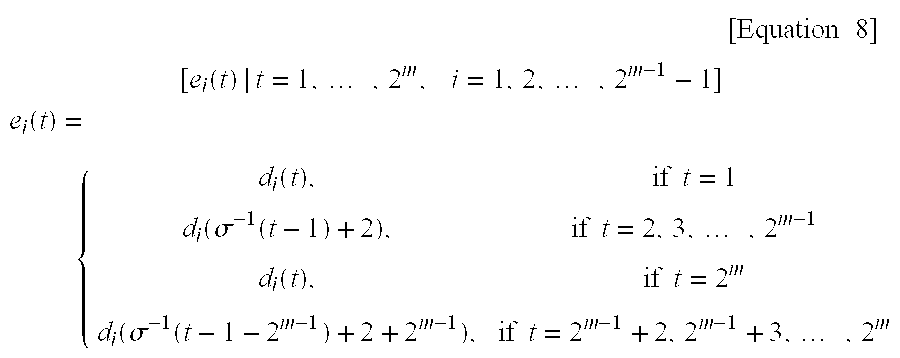
Thereafter, in step 519, quasi-orthogonal codes are arranged as shown in FIG. 4 using the sequences generated in the above process, in accordance with Equation (9) below.
[S ij(t)|t=1,2, . . . ,2m ]S ij(t)=e i(t)+W j(t)(mod 2), i=0,1,2, . . . ,2m−1−2, j=0,1, . . . ,2m−1  [Equation 9]
At this point, [Wj(t)|t=1,2, . . . ,2m, j=0,1, . . . ,2m−1] represents a Walsh sequence, being an orthogonal code, which is expressed with symbols of “0” and “1”.
A detailed description will be now made regarding the procedure for generating binary quasi-orthogonal code masks with reference to FIG. 5, by way of example.
Herein, it is assumed that ƒ(x)=x3+x+1 is used for the binary primitive polynomial. Accordingly, in step 511, let the root of g(x) be β to determine specific sequences. That is, β3+β+1=0. For convenience, β, β2, β3, β4, β5, β6 and β7 will first be determined, as follows.
β=β
β22
β3=β+1
β42
β532=(β+1)+β22+β+1
β632+β=(β+1)+β2+β=β2+1
β73+β=(β+1)+β=1
When γ=β0=1, σ1(1·βt) and σ2(1·βt) will be determined prior to determining Q1(t,x1)=σ2(1·βt)+x1σ1(1·βt). σ 1 ( β t ) = 2 S = 0 ( β t ) 2 S
Figure US06731674-20040504-M00015
will be determined as follows: for t = 0 , T ( 1 ) = 2 S = 0 1 2 S = 1 + 1 + 1 = 1 for t = 1 , T ( β ) = 2 S = 0 β 2 S = β + β 2 + β 4 = β + β 2 + ( β + β 2 ) = 0 for t = 2 , T ( β 2 ) = 2 S = 0 ( β 2 ) 2 S = β 2 + β 4 + β 8 = β 2 + β 4 + β = 0 for t = 3 , T ( β 3 ) = 2 S = 0 ( β 3 ) 2 S = β 3 + β 6 + β 12 = β 3 + β 6 + β 5 = 1 for t = 4 , T ( β 4 ) = 2 S = 0 ( β 4 ) 2 S = β 4 + β 8 + β 16 = β 4 + β + β 2 = 0 for t = 5 , T ( β 5 ) = 2 S = 0 ( β 5 ) 2 S = β 5 + β 10 + β 20 = β 5 + β 3 + β 6 = 1 for t = 6 , T ( β 6 ) = 2 S = 0 ( β 6 ) 2 S = β 6 + β 12 + β 24 = β 6 + β 5 + β 3 = 1
Figure US06731674-20040504-M00016
σ 2 ( β t ) = ( m - 2 ) / 2 S = 0 T γ ( ( β t ) 1 + 2 S )
Figure US06731674-20040504-M00017
for t = 0 , σ 2 ( 1 ) = 1 S = 0 T γ ( 1 1 + 2 S ) = T γ ( 1 ) + T γ ( 1 ) = 1 + 1 = 0 for t = 1 , σ 2 ( β ) = 1 S = 0 T γ ( β 1 + 2 S ) = T γ ( β ) + T γ ( β 3 ) = 0 + 1 = 1 for t = 2 , σ 2 ( β 2 ) = 1 S = 0 T γ ( ( β 2 ) 1 + 2 S ) = T γ ( β 2 ) + T γ ( β 6 ) = 0 + 1 = 1 for t = 3 , σ 2 ( β 3 ) = 1 S = 0 T γ ( ( β 3 ) 1 + 2 S ) = T γ ( β 3 ) + T γ ( β 9 ) = T γ ( β 3 ) + T γ ( β 2 ) = 1 + 0 = 1 for t = 4 , σ 2 ( β 4 ) = 1 S = 0 T γ ( ( β 4 ) 1 + 2 S ) = T γ ( β 4 ) + T γ ( β 12 ) = T γ ( β 4 ) + T γ ( β 5 ) = 0 + 1 = 1 for t = 5 , σ 2 ( β 5 ) = 1 S = 0 T γ ( ( β 5 ) 1 + 2 S ) = T γ ( β 5 ) + T γ ( β 15 ) = T γ ( β 5 ) + T γ ( β ) = 1 + 0 = 1 for t = 6 , σ 2 ( β 6 ) = 1 S = 0 T γ ( ( β 6 ) 1 + 2 S ) = T γ ( β 6 ) + T γ ( β 18 ) = T γ ( β 6 ) + T γ ( β 4 ) = 1 + 0 = 1
Figure US06731674-20040504-M00018
Therefore, when γ=β0=1, the left sequence (for x1=0) becomes Q1(t,0)=σ2t)=1001011 and the right sequence (for x1=1) becomes Q1(t,1)=σ2t)+σ1t)=1110100.
In addition, when γ=β1=β, Qβ(t,x1)=σ2(β·βt)+x1σ1(β·βt)=σ2t+1)+x1σ1t+1)=Q1(t+1,x1). Therefore, the sequence Qβ(t,x1) for γ=β1=β is equal to the result obtained by shifting once the sequence Q1(t,x1) for γ=β0=1.
In this manner, it is possible to determine the left sequence 1001011, the right sequence 1110100 and their shifted sequences. Herein, a sequence shifted i times will be referred to as Si.
In step 513, an m-sequence is generated in accordance with the polynomial ƒ(x)=x3+x+1. Here, the m-sequence according to the polynomial ƒ(x)=x3+x+1 will become 1001011. A column permutation function for converting the m-sequence to a Walsh orthogonal code in accordance with Equation (8) is calculated using the m-sequence 1001011. Equation (8) implies that the m-sequence is converted into decimal numbers by grouping the m-sequence by three consecutive terms. That is, the first three terms 100 are converted to decimal number 4; the second three terms 001 are converted to decimal number 1; the third three terms 010 are converted to decimal number 2, the fourth three terms 101 are converted to decimal number 5; the fifth three terms 011 are converted to decimal number 3; the sixth three terms 111 are converted to decimal number 7; and the seventh three terms 110 are converted to decimal number 6. The foregoing results can be expressed as: for t = 0 , σ ( 0 ) = 2 S = 0 m ( 0 + S ) 2 2 - S = 4 × m ( 0 ) + 2 × m ( 1 ) + m ( 2 ) = ( 100 ) 2 = 4 for t = 1 , σ ( 1 ) = 2 S = 0 m ( 1 + S ) 2 2 - S = 4 × m ( 1 ) + 2 × m ( 2 ) + m ( 3 ) = ( 001 ) 2 = 1 for t = 2 , σ ( 2 ) = 2 S = 0 m ( 2 + S ) 2 2 - S = 4 × m ( 2 ) + 2 × m ( 3 ) + m ( 4 ) = ( 010 ) 2 = 2 for t = 3 , σ ( 3 ) = 2 S = 0 m ( 3 + S ) 2 2 - S = 4 × m ( 3 ) + 2 × m ( 4 ) + m ( 5 ) = ( 101 ) 2 = 5 for t = 4 , σ ( 4 ) = 2 S = 0 m ( 4 + S ) 2 2 - S = 4 × m ( 4 ) + 2 × m ( 5 ) + m ( 6 ) = ( 011 ) 2 = 3 for t = 5 , σ ( 5 ) = 2 S = 0 m ( 5 + S ) 2 2 - s = 4 × m ( 5 ) + 2 × m ( 6 ) + m ( 7 ) = ( 111 ) 2 = 7 for t = 6 , σ ( 6 ) = 2 S = 0 m ( 6 + S ) 2 2 - S = 4 × m ( 6 ) + 2 × m ( 7 ) + m ( 8 ) = ( 110 ) 2 = 6
Figure US06731674-20040504-M00019
The calculated column permutation functions are shown in Table 3A.
TABLE 3A
t Three Consecutive Terms σ(t)
0 100 4
1 001 1
2 010 2
3 101 5
4 011 3
5 111 7
6 110 6
In step 515, “0” is added at the head of every left sequence determined in step 511 and then arranged; succeedingly, “0” is added at the head of every right sequence and then arranged. With regard to the expression of di(t) in accordance with Si(t), when i=0, d0(t) is the binary sequence S0(t), at the head of which “0” is added, determined in step 511 for γ=β0=1. That is, if S0(1)=1, S0(2)=0, S0(3)=0, S0(4)=1, S0(5)=0, S0(6)=1, S0(7)=1, S0(8)=1, S0(9)=1, S0(10)=1, S0(11)=0, S0(12)=1, S0(13)=0 and S0(14)=0 as determined in step 511, then d0(t) can be determined as follows:
d0(1)=0
d0(2)=S0(2−1)=S0(1)=1
d0(3)=S0(3−1)=S0(2)=0
d0(4)=S0(4−1)=S0(3)=0
d0(5)=S0(5−1)=S0(4)=1
d0(6)=S0(6−1)=S0(5)=0
d0(7)=S0(7−1)=S0(6)=1
d0(8)=S0(8−1)=S0(7)=1
d0(9)=0
d0(10)=S0(10−2)=S0(8)=1
d0(11)=S0(11−2)=S0(9)=1
d0(12)=S0(12−2)=S0(12)=1
d0(13)=S0(13−2)=S0(11)=1
d0(14)=S0(14−2)=S0(12)=1
d0(15)=S0(15−2)=S0(13)=1
d0(16)=S0(16−2)=S0(14)=1
In addition, when i=1, d0(t) is the binary sequence S1(t), at the head of which “0” is added, determined in step 511 for γ=β1=β. That is, when S1(1)=0, S1(2)=0, S1(3)=1, S1(4)=0, S1(5)=1, S1(6)=1, S1(7)=1, S1(8)=1, S1(9)=1, S1(10)=0, S1(11)=1, S1(12)=0, S1(13)=0 and S1(14)=1 as determined in step 511, d1(t) can be determined as follows.
d1(1)=0
d1(2)=S1(2−1)=S1(1)=0
d1(3)=S1(3−1)=S1(2)=0
d1(4)=S1(4−1)=S1(3)=1
d1(5)=S1(5−1)=S1(4)=0
d1(6)=S1(6−1)=S1(5)=1
d1(7)=S1(7−1)=S1(6)=1
d1(8)=S1(8−1)=S1(7)=1
d1(9)=0
d1(10)=S1(10−2)=S1(8)=1
d1(11)=S1(11−2)=S1(9)=1
d1(12)=S1(12−2)=S1(10)=0
d1(13)=S1(13−2)=S1(11)=1
d1(14)=S1(14−2)=S1(12)=0
d1(15)=S1(15-2)=S1(13)=0
d1(16)=S1(16-2)=S1(14)=1
Table 3B below shows the forgoing results, wherein ci (i=0 to 15) denotes an i-th column.
TABLE 3B
di(t) c0 c1 c2 c3 c4 c5 c6 c7 c8 c9 c10 c11 c12 c13 c14 c15
d1(t) 0 1 0 0 1 0 1 1 0 1 1 1 0 1 0 0
d2(t) 0 0 0 1 0 1 1 1 0 1 1 0 1 0 0 1
d3(t) 0 0 1 0 1 1 1 0 0 1 0 1 0 0 1 1
d4(t) 0 1 0 1 1 1 0 0 0 0 1 0 0 1 1 1
d5(t) 0 0 1 1 1 0 0 1 0 1 0 0 1 1 1 0
d6(t) 0 1 1 1 0 0 1 0 0 0 0 1 1 1 0 1
d7(t) 0 1 1 0 0 1 0 1 0 0 1 1 1 0 1 0
In step 517, the shifted arranged specific sequences of Table 3B are column permutated with the column permutation functions determined in step 513. Shown in Table 3C below are the binary sequences of Table 3B which are column permuted with the column permutation function determined in step 513.
TABLE 3C
ei(t) c0 c4 c1 c2 c5 c3 c7 c6 c8 c12 c9 c10 c13 c11 c15 c14
e0(t) 0 1 1 0 0 0 1 1 0 0 1 1 1 1 0 0
e1(t) 0 0 0 0 1 1 1 1 0 1 1 1 0 0 1 0
e2(t) 0 1 0 1 1 0 0 1 0 0 1 0 0 1 1 1
e3(t) 0 1 1 0 1 1 0 0 0 0 0 1 1 0 1 1
e4(t) 0 1 0 1 0 1 1 0 0 1 1 0 1 0 0 1
e5(t) 0 0 1 1 0 1 0 1 0 1 0 0 1 1 1 0
e6(t) 0 0 1 1 1 0 1 0 0 1 0 1 0 1 0 1
By connecting the above left and right sequences of length 8, it is possible to create binary quasi-orthogonal code mask candidates of length 16 shown in Table 3D.
TABLE 3D
e0(t) : 0 1 1 0 0 0 1 1 0 0 1 1 1 1 0 0
e1(t) : 0 0 0 0 1 1 1 1 0 1 1 1 0 0 1 0
e2(t) : 0 1 0 1 1 0 0 1 0 0 1 0 0 1 1 1
e3(t) : 0 1 1 0 1 1 0 0 0 0 0 1 1 0 1 1
e4(t) : 0 1 0 1 0 1 1 0 0 1 1 0 1 0 0 1
e5(t) : 0 0 1 1 0 1 0 1 0 1 0 0 1 1 1 0
e6(t) : 0 0 1 1 1 0 1 0 0 1 0 1 0 1 0 1
In summary, the left and right binary sequences are independently column shifted and arranged. Then, “0” is added to every left and right sequence to crease left and right sequences of length 8. Thereafter, the left and right sequences are column permuted according to the column permutation function, respectively. The column permuted left and right sequences are connected to crease quasi-orthogonal code mask candidate functions of length 16.
Alternatively, after column shifting the left and right binary sequences, arranging the column shifted sequences and then column permuting the arranged left and right sequences according to the column permutation function, “0” can be added at the head of the column shifted left and right sequences to generate the left and right sequences of length 8.
The created binary quasi-orthogonal code mask candidates are added to Walsh orthogonal codes to verify whether Condition 3 is satisfied.
Thereafter, in step 519, sequences satisfying Condition 3 are selected from the (2m−1−1)*2m quasi-orthogonal code candidates, and the used quasi-orthogonal code mask candidate is selected as a quasi-orthogonal code mask. That is, after the process of step 517, in step 519, sequences satisfying Condition 3, are selected from the determined mask candidate families. With regard to the selecting method, every Walsh orthogonal code and a correlation for every length are determined to examine whether Condition 3 is satisfied, and accordingly selected as a mask when condition 3 is satisfied.
For example, for an orthogonal code of length 128, a partial correlation with every Walsh orthogonal code of length 64 is determined to examine whether the partial correlation exceeds 8. When the partial correlation exceeds 8, it is not selected as a mask; otherwise, when satisfied, a partial correlation is calculated again for partial length 32 with respect to the mask candidate. Then, it is examined whether the partial correlation value exceeds 8. When the partial correlation exceeds 8, it is not selected as a mask; otherwise, when satisfied, the same operation is performed for the next length. After performing the above process for the partial length of up to 4, a mask candidate having passed all of the above conditions is selected as a quasi-orthogonal code mask candidate satisfying Conditions 1 to 3.
Quasi-orthogonal code sequences generated using the process of FIG. 5 are determined by the mask function ei(t). That is, when the mask function ei(t) satisfy Conditions 1 to 3, it is, possible to obtain 2m quasi-orthogonal codes. Therefore, if k masks satisfying Conditions 1 to 3 exist, it is possible to obtain k×2m quasi-orthogonal codes. Table 4 below shows the number of quasi-orthogonal codes according to the m-sequence. Further, Tables 5, 6 and 7 below show the quasi-orthogonal code sequence mask functions ei(t) for m=6, m=7 and m=8, respectively, determined in the above process.
TABLE 4
m characteristic polynomial # of Quasi-orthogonal sequences
6 100101  8 * 64
7 10000011 22 * 128
8 10001001 20 * 256
TABLE 5
f(X) = 1 + X + X5 (Binary Expression)
e1 : 0001010000100111010000011000110100100111000101000111001010111110
e2 : 0001001000011101011101000111101101001000101110001101000100100001
e3 : 0001010000011011000101001110010001111101100011011000001010001101
e4 : 0001001001000111010001110001001001110100001000011101111010001011
e5 : 0001000100011110001000100010110101110111011110000100010001001011
e6 : 0001011101000010011111100010101101111110110101000001011110111101
e7 : 0001010001110010001001110100000100101000101100011110010001111101
e8 : 0001011101111110011100011110011100100100010011011011110100101011
TABLE 6
f(X) = 1 + X + X7 (Hexadecimal Expression)
 e1 : 17422b8118b2db8e2b7ee842248e184d
 e2 : 177e2b427e17bdd47ee8bd2be87ed442
 e3 : 144e4eeb7dd8277d4eeb144ed8828227
 e4 : 111e2ddd1eeeddd2444b78884bbb8887
 e5 : 171871814d422bdb4d422bdbe8e78e7e
 e6 : 121d47b7121db8481ded4847e2124847
 e7 : 17182bdb2b24e8187e7142b2bdb27e8e
 e8 : 142741724172ebd872412714d8eb7241
 e9 : 114b228744e1772d2d771ebb8722b4ee
e10 : 1178771e2dbb4bdd77e1ee784b22d2bb
e11 : 112d784477b4e1221edd884b87bbeed2
e12 : 11782d444bdd881e44d287111e77224b
e13 : 172471422be74d8118d47eb224174271
e14 : 147214727d1b82e4284e284e4127bed8
e15 : 122e122e7b4784b8477bb8842e122e12
e16 : 121d1ded747b7b8b2ede212eb747b8b7
e17 : 141b41b127d78d8227d7727d141bbe4e
e18 : 122e48741d21477b7448d1ed7b47dee2
e19 : 141b1beb41b14e4114e41b14414e4ebe
e20 : 1274127448d1b72e12741274b72e48d1
e21 : 111e778778881e11777811e11eee7877
e22 : 14724e281b7d41271b7d412714724e28
TABLE 7
f(X) = 1 + X3 + X7 (Hexadecimal Expression)
 e1 : 112d77b4447822e11e2278bbb488d211112d77b4447822e1e1dd87444b772dee
 e2 : 121d47487484de2e21d18b7bb8b7ede27b8b2edee2ed48474847e2ed2ede7b8b
 e3 : 171824d44d427e8e717e42b22b2418e84d427e8e171824d4d4dbe7178e81bd4d
 e4 : 127448d121b87b1d48d1ed8b84e221b81274b72ede477b1d48d112747b1d21b8
 e5 : 1247217448e27bd112bBde74b7e27b2e1db72e84b8ed8bdee2b72e7bb81274de
 e6 : 142714d87db182b127ebd8eb4e7d4e8272be7241e4d71bd74172be72d71bd7e4
 e7 : 141b7d8d727d1beb7d8d141be4148d8227d74e4141b12827b1bed828282741b1
 e8 : 117878112d44bbd22dbbbb2d118778ee442d2d4487ee11788711118744d22dbb
 e9 : 147227417de4b1282741eb8db128821b28b11b82bed87214e47d28b18debbed8
e10 : 141b4e41414ee4eb28278d827d7227284ebeeb1be414be4e728228d8d8287d8d
e11 : 144e4eeb1bbebee4144e4eebe441411b7228d7728227d8828dd7288d8227d882
e12 : 112d1e224b88bb784b88bb78eed2e1dd784488b422e12deedd1ed211784488b4
e13 : 1274482e47211d7b7412d1b7deb87b1d7b1d2147d1b78bed1d7bb8de482eed8b
e14 : 17242b1871424d7e71bd4d8117db2be72be717db4d8171bdb2818ebdd4e7e8db
e15 : 144e288d277de4412782e4beeb4ed78d4e1472d782d841e48227411bb1148dd7
e16 : 111e11e122d2ddd24bbb4b44787787771eeee1ee2d222ddd444bbb4b77877778
e17 : 127447211274b8de1d7bb7d1e284b7d1128bb821ed74b8211d8448d11d84b72e
e18 : 112d774b1edd78bb78bbe122774beed2448722e1b488d2eed2ee4b7722e1bb78
e19 : 177e7ee8422b2bbd7e17e87e2b42bd2b244d4ddb8ee7e771b2db24b218718e18
e20 : 111e222d444b7778111e222d444b77781e112d224b447877e1eed2ddb4bb8788
Therefore, when an increased number of orthogonal codes are required in a system using Walsh orthogonal codes, it is possible to increase channel capacity, by using the quasi-orthogonal codes generated according to the present invention. In such a case, the quasi-orthogonal codes have limited interference with the Walsh orthogonal codes and provide a fixed correlation value. For example, when N=64, a correlation value between the quasi-orthogonal code and the Walsh orthogonal code is 8 or −8. Further, even when N=256, a partial correlation value (for length N=64) is also 8 or −8. This means that it is possible to accurately predict the interference, providing excellent characteristics.
The above quasi-orthogonal codes can be used for every link in the CDMA system using the Walsh orthogonal codes. When the quasi-orthogonal codes are used together with the orthogonal codes, the following three options can be considered.
Option 1
In a system using the Walsh orthogonal codes and providing a service at a variable data rate, it is possible to freely use the binary quasi-orthogonal codes without restriction as to the length. Further, it is possible to use every binary quasi-orthogonal code sequence at full length.
Option 2
One Walsh orthogonal code group and a binary quasi-orthogonal code group is selected to make two orthogonal sets, and the two groups both can provide a service at the variable data rate.
Option 3
It is possible to use the Walsh orthogonal code group and every binary quasi-orthogonal code group as one group to allow every code group to support the variable data rate. In this case, a random code characteristic between the binary quasi-orthogonal code groups may occur.
It is preferable to use the quasi-orthogonal codes according to the application, taking into consideration the above three options. In general, when only the Walsh orthogonal codes are used, the modulating side exchanges a predetermined orthogonal code number with the demodulating side. Therefore, when the orthogonal codes and the quasi-orthogonal codes are used, it is necessary to exchange a predetermined orthogonal code number and a group number (i.e., an index i of the Q′ matrix ei(t) shown in FIG. 4). In this case, the orthogonal code group is defined as a Group 0, and subsequently, the group numbers are redefined up to 2m−1.
A description will now be made regarding a method for applying the quasi-orthogonal code group to a system supporting the variable data rate, like the orthogonal code group. Each element of the quasi-orthogonal code group is comprised of an orthogonal code number and a group number. The group number indicates which ei(t) is selected in FIG. 4. To service the variable data rate using the quasi-orthogonal code group, a previously allocated orthogonal code number is used as a Walsh orthogonal code number and then, the allocated ei(t) is added to it for every length N.
FIG. 6 illustrates a channel separation method using the Walsh orthogonal codes and the quasi-orthogonal codes in an IS-95/IS-95A forward link to extend the channel capacity according to an embodiment of the present invention. FIG. 6 shows an exemplary embodiment where the Walsh orthogonal codes represented by Wi (i=0 to 63) are assigned to various channels and the quasi-orthogonal codes of length 256 represented by Sj (j=0 to 255) are assigned to traffic channels. Therefore, an IS-95/IS-95A forward link can separate 64 channels using the Walsh orthogonal codes, and 256 channels, which is 4 times the number of the Walsh orthogonal codes, using the quasi-orthogonal codes. Therefore, it is possible to increase the channel capacity by using the Walsh orthogonal codes and the quasi-orthogonal codes.
FIG. 7 illustrates a channel transmitter which separates channels using the quasi-orthogonal codes generated according to the present invention. The mobile communication system shown in FIG. 7 constructs the channel bit streams in a method different from the IS-95 standard.
Referring to FIG. 7, a signal converter (or demultiplexing & signal mapping part) 711 receiving a data bit stream X, separates the received data bit stream into odd-numbered bits and even-numbered bits to demultiplex the separated signals into I and Q signals, and then converts the separated I and Q signals by converting a signal “0” to “+1” and a signal “1” to “−1”. A quasi-orthogonal code (QOC) generator 713, receiving quasi-orthogonal code mask index and a Walsh orthogonal code (WOC) mask index, generates a quasi-orthogonal code QOFk. An orthogonal spreader 715 channel spreads the signals output from the signal converter 711 with the quasi-orthogonal code QOFk generated from the quasi-orthogonal code generator 713. A PN code generator 717 generates complex PN codes PNi and PNq. A PN spreader 719 PN masks the orthogonally spread signals di and dq with PNi and PNq, respectively. A baseband filter 721 filters the PN spread signals Xi and Xq into baseband signals. A frequency shifter 723 up-converts the baseband filtered signals Xi and Xq to RF signals.
Although FIG. 7 illustrates one channel transmitter using the quasi-orthogonal code in a CDMA communication system, when the transmitter includes N channels, the corresponding number of orthogonal spreaders should be provided which use the quasi-orthogonal codes.
Referring to FIG. 7, binary input signals expressed as “0” and “1” are demultiplexed into I and Q signals by the signal converter 711, and then converted in a such manner that a signal “0” is converted to “+1” and a signal “1” to “−1”. The quasi-orthogonal code generator 713 then generates a quasi-orthogonal code QOFk according to the received quasi-orthogonal code mask index and Walsh orthogonal code mask index. The orthogonal spreader 715 multiplies the signals output from the signal converter 711 by the quasi-orthogonal code QOFk to spread a transmission signal on the corresponding channel.
The quasi-orthogonal code generator 713 can be implemented using two different methods.
Using a first method, the quasi-orthogonal code generator 713 includes a memory shown in FIG. 11 to generate the quasi-orthogonal codes. That is, every quasi-orthogonal sequence is stored in the memory as shown in FIG. 11 to output the quasi-orthogonal sequence according to the quasi-orthogonal code mask index and the Walsh orthogonal code index. Further, the quasi-orthogonal code generator 713 stores all the available quasi-orthogonal sequences in the memory, and upon receipt of a quasi-orthogonal code index q and an orthogonal code index p, outputs (q*2m+p)-th quasi-orthogonal sequence QOFq×2 m +p. In FIG. 11, upper 2m sequences are Walsh orthogonal code sequences, and the other sequences are quasi-orthogonal code sequences.
In a second method, the quasi-orthogonal code generator 713 is implemented as shown in FIG. 8.
Referring to FIG. 8, a quasi-orthogonal code mask generator 811 storing quasi-orthogonal code masks e0-eN, outputs a quasi-orthogonal code mask ei according to a received quasi-orthogonal code mask index. That is, the quasi-orthogonal code mask generator 811 includes a table for quasi-orthogonal code masks ei, which can be implemented as shown in FIG. 9. Referring to FIG. 9, since e0=0, when e0 is selected, a Walsh orthogonal code is output which is generated from a Walsh orthogonal code generator 813. The Walsh orthogonal code generator 813 storing Walsh orthogonal codes, outputs a Walsh orthogonal code Wj according to a received Walsh orthogonal code index. The Walsh orthogonal code generator 813 includes a Walsh orthogonal code table, which can be implemented as shown in FIG. 10. An adder 815 adds the quasi-orthogonal code mask ei output from the quasi-orthogonal code mask generator 811 and the Walsh orthogonal code Wj output from the Walsh orthogonal code generator 813 to generate a quasi-orthogonal code QOFk.
A signal spread with the quasi-orthogonal code is applied to the PN spreader 719. The PN spreader 719 then spreads the signals di and dq output from the orthogonal spreader 715 with corresponding PN codes PNi and PNq, thereby performing PN masking. The PN masked signals Xi and Xq are baseband filtered by the baseband filter 721, and the baseband filtered signals are converted to RF signals by the frequency shifter 723.
FIG. 12 illustrates a channel transmitter which uses a Walsh orthogonal code and a quasi-orthogonal code according to an embodiment of the present invention, in a CDMA communication system. FIG. 12 shows an example in which when transmitting at least two transmission signals, the transmission signals of the respective channel transmitters are spread with unique quasi-orthogonal codes or unique Walsh orthogonal codes. In FIG. 12, a first channel signal and a second channel signal can be signals on dedicated channels, or signals on a dedicated channel and a common channel. The dedicated channel includes a fundamental channel, a supplemental channel and a dedicated control channel, and the common channel includes a common control channel, a pilot channel, a sync channel and a paging channel. In the embodiment, the common channels use Walsh orthogonal codes, and the dedicated channels use either the Walsh orthogonal codes or the quasi-orthogonal codes.
Referring to FIG. 12, a first signal converter 1211. demultiplexes a received first channel beat stream to I and Q arms, and then converts the demultiplexed signals. That is, the first signal converter 1211 converts a signal “0” of the received first channel bit stream to “+1” and a signal “1” to “−1”, and provides the converted signals to an orthogonal code spreading and PN masking part 1219. Similarly, a second signal converter 1213 demultiplexes a received second channel bit stream to I and Q arms, and then converts the demultiplexed signals. The second signal converter 1213 converts a signal “0” of the received second channel bit stream to “+1” and a signal “1” to “−1”, and provides the converted signals to the orthogonal code spreading and PN masking part 1219.
An orthogonal code generator 1215 receiving a quasi-orthogonal code (QOC) mask index and a Walsh orthogonal code (WOC) index, generates a Walsh orthogonal code Wj or a quasi-orthogonal code Si using the received indexes and provides the generated code to the orthogonal code spreading and PN masking part 1219. Here, the number of orthogonal code generators 1215 should equal the number of the channel transmitters. For example, in FIG. 12, to separately provide orthogonal codes for the first channel and the second channel, there are required two orthogonal code generators. In addition, the orthogonal code generator 1215 should be able to generate quasi-orthogonal codes and Walsh orthogonal codes according to the quasi-orthogonal code mask index and the Walsh orthogonal code index designated by an upper processor, as shown in FIG. 8.
A PN code generator 1217 generates real and imaginary PN codes PNi and PNq and provides them to the orthogonal code spreading and PN masking part 1219. The orthogonal code spreading and PN masking part 1219 multiplies outputs of the first and second signal converters 1211 and 1213 by associated unique Walsh orthogonal codes Wj or quasi-orthogonal codes Si to spread the input signals, and again multiplies the spread signals by the PN codes PNi and PNq to generate PN masked signals Xi and Xq. A baseband filter 1221 filters the signals Xi and Xq output from the orthogonal code spreading and PN masking part 1219 to baseband signals. A frequency shifter 1223 frequency-shifts the signals output from the baseband filter 1221 to RF signals.
To ensure a high correlation property for multipath delay, the orthogonal code spreading and PN masking part 1219 can be implemented in various configurations. FIG. 13 illustrates an orthogonal code spreading and PN masking part implemented by a complex multiplier 1319 for complex PN masking, which uses a quasi-orthogonal code Si for the first channel and a Walsh orthogonal code Wi for the second channel. In addition, the complex multiplier 1319 can also be equally applied to the case where the quasi-orthogonal codes Si are used for both the first and second channels to perform complex PN masking. FIG. 14 illustrates an orthogonal code spreading and PN masking part, which employs non-complex PN masking and uses a Walsh orthogonal code Wi for the first channel and a quasi-orthogonal code Si for the second channel. In addition, the same scheme can also be equally applied to the case where the quasi-orthogonal codes Si are used for both the first and second channels and complex PN masking is not employed. In FIGS. 13 and 14, the number of channel spreaders and orthogonal code generators provided as equal the number of channels. Further in FIG. 13, there is required only one complex multiplier.
Referring to FIG. 13, a first spreader 1311 receiving a first channel signal, multiplies the received first channel signal by a quasi-orthogonal code Si to output spread signals di1 and dq1. A second spreader 1313 receiving a second channel signal, multiplies the received second channel signal by a Walsh orthogonal code Wi to output spread signals di2 and dq2. A repeater 1317 repeats the PN codes PNi and PNq output from the PN code generator 1217 at predetermined times. The complex multiplier 1319 adds the signal di1 to the signal di2 and the signal dq1 to dq2, output from the first and second spreaders 1311 and 1313; and complex multiplies the added signals di1+di2 and dq1+dq2 by the PN codes PNi and PNq output from the repeater 1317, respectively, to generate PN masked signals Xi and Xq. The complex multiplier 1319 performs complex PN masking by performing the complex operation shown in FIG. 13.
In FIG. 13, with regard to the quasi-orthogonal code Si and the Walsh orthogonal code Wi assigned to the first and second channels, sub-codes constituting the orthogonal codes should also be different from each other. Therefore, in the case where the orthogonal code spreading and PN masking part 1219 is implemented in this manner, it is possible to acquire accurate arrival time synchronization between the first channel and the second channel, thereby removing mutual interference between them.
FIG. 14 illustrates the orthogonal code spreading and PN masking part 1219, wherein the Walsh orthogonal code Wi is used for the first channel and the quasi-orthogonal code Si is used for the second channel, and non-complex PN masking is employed.
Referring to FIG. 14, a first spreader 1411 receiving a first channel signal, multiplies the received first channel signal by a Walsh orthogonal code Wi to output spread signals di1 and dq1. Similarly, a second spreader 1413 receiving a second channel signal, multiplies the received second channel signal by a quasi-orthogonal signal Si to output spread signals di2 and dq2. An adder 1415 adds the spread signal di1 output from the first spreader 1411 to the spread signal di2 output from the second spreader 1413 to generate a signal di1+di2. An adder 1417 adds the spread signal dq1 output from the first spreader 1411 to the spread signal dq2 output from the second spreader 1413 to generate a signal dq1+dq2. A repeater 1421 repeats the PN codes PNi and PNq output from the PN code generator 1217 at predetermined times. A multiplier 1423 multiplies the spread signal di1+di2 output from the adder 1415 by the PN code PNi output from the repeater 1421 to generate a masked signal Xi. A multiplier 1425 multiplies the spread signal dq1+dq2 output from the adder 1417 by the PN code PNq to generate a masked signal Xq.
In FIG. 14, as stated above, the Walsh orthogonal code Wi assigned to the first channel should be different from the quasi-orthogonal code Si assigned to the second channel. In the case where the orthogonal code spreading and PN masking part 1219 is implemented in this manner, it is possible to acquire accurate arrival time synchronization between the first channel and the second channel, thereby removing mutual interference between them.
As described above, the embodiment can generate quasi-orthogonal codes having the least interference with Walsh orthogonal codes. Further, in a mobile communication system which separates channels using the Walsh orthogonal codes, it is possible to increase channel capacity by using the quasi-orthogonal codes regardless of the limitation on the Walsh orthogonal codes.
While the invention has been shown and described with reference to a certain preferred embodiment thereof, it will be understood by those skilled in the art that various changes in form and details may be made therein without departing from the spirit and scope of the invention as defined by the appended claims.

Claims (9)

What is claimed is:
1. A method for generating a binary quasi-orthogonal code in a code division multiple access (CDMA) communication system, comprising the steps of:
(a) generating an m-sequence, and specific left and right sequences having a full correlation property which have a specific bound of correlation value with the m-sequence;
(b) column permuting the specific left and right sequences in a column permutation method used when converting the m-sequence to a Walsh orthogonal code respectively, and connecting the left sequences to the right sequences to generate mask candidates;
(c) operating the mask candidates and the Walsh orthogonal codes having the same length as the mask candidates to generate quasi-orthogonal code candidate families; and
(d) selecting a quasi-orthogonal code out of the generated quasi-orthogonal code candidate families, wherein the selected quasi-orthogonal code satisfies a partial correlation property with the Walsh orthogonal codes, and selecting a mask corresponding to generation of the selected quasi-orthogonal code.
2. The method as claimed in claim 1, wherein the specific left and right sequences are Kerdock codes of a Family A sequence, for generating binary quasi-orthogonal code masks.
3. The method as claimed in claim 2, wherein said step (b) comprises the steps of:
(1) independently shifting the specific left and right sequences, to generate shifted left and right sequences;
(2) independently column permuting the specific left and right sequences and the shifted left and right sequences with a column permutation function; and
(3) connecting the column permuted left sequences to the column permuted right sequences to generate binary quasi-orthogonal code mask candidates.
4. The method as claimed in claim 3, wherein said step (1) comprises the step of inserting “0” at the head of the shifted left and right sequences.
5. The method as claimed in claim 2, wherein a mask for generating the binary quasi-orthogonal code is selected as a binary quasi-orthogonal code mask when a correlation value of each part of N/M does not exceed {square root over (N/M)}, where N is the whole length of the binary quasi-orthogonal code candidate and the Walsh orthogonal code, M=2m, and m=0,1, . . . ,log2N, in the step (d).
6. The method as claimed in claim 5, further comprising the step of storing a mask for generating the binary quasi-orthogonal code as the binary quasi-orthogonal code mask when a correlation value of each part of N/M does not exceed {square root over (N/M)}, where N is the whole length of a binary quasi-orthogonal code candidate generated with the mask and another binary quasi-orthogonal code candidate, M=2m, and m=0,1, . . . ,log2N.
7. A channel transmission device for a CDMA communication system, comprising:
a generator for generating a binary quasi-orthogonal code by operating a binary quasi-orthogonal code mask and a Walsh orthogonal code corresponding to designated mask index and Walsh orthogonal code index, respectively;
a channel spreader for operating input signals and the generated binary quasi-orthogonal codes to generate channel spread signals; and
a PN (Pseudo Noise) masking part for operating the channel spread signals and PN sequences to generate PN masked channel signals.
8. The channel transmission device as claimed in claim 7, wherein the binary quasi-orthogonal code generator comprises:
a first generator for generating the binary quasi-orthogonal code mask corresponding to the designated mask index;
a second generator for generating the Walsh orthogonal code corresponding to the designated Walsh orthogonal code; and
an adder for operating the binary quasi-orthogonal code mask and the Walsh orthogonal code to generate a binary quasi-orthogonal code.
9. A channel transmission method for a CDMA communication system, comprising the steps of:
generating a binary quasi-orthogonal code mask corresponding to a designated quasi-orthogonal code index, and generating a binary quasi-orthogonal code by operating the generated binary quasi-orthogonal code mask and a Walsh orthogonal code;
operating input signals and the generated binary quasi-orthogonal codes to generate channel spread signals; and
operating the channel spread signals and complex PN sequences to generate PN masked channel signals.
US09/405,333 1998-09-25 1999-09-24 Device and method for generating quasi-orthogonal code and spreading channel signals in mobile communication system Expired - Lifetime US6731674B1 (en)

Applications Claiming Priority (2)

Application Number Priority Date Filing Date Title
KR98/40408 1998-09-25
KR19980040408 1998-09-25

Publications (1)

Publication Number Publication Date
US6731674B1 true US6731674B1 (en) 2004-05-04

Family

ID=19552295

Family Applications (1)

Application Number Title Priority Date Filing Date
US09/405,333 Expired - Lifetime US6731674B1 (en) 1998-09-25 1999-09-24 Device and method for generating quasi-orthogonal code and spreading channel signals in mobile communication system

Country Status (9)

Country Link
US (1) US6731674B1 (en)
EP (1) EP1034665B1 (en)
CN (1) CN1130867C (en)
AU (1) AU749559B2 (en)
BR (1) BR9909592A (en)
CA (1) CA2310815C (en)
DE (1) DE69916787T2 (en)
RU (1) RU2216880C2 (en)
WO (1) WO2000019730A2 (en)

Cited By (9)

* Cited by examiner, † Cited by third party
Publication number Priority date Publication date Assignee Title
US20020085619A1 (en) * 2000-10-20 2002-07-04 Samsung Electronics Co., Ltd. Apparatus and method for transmitting a burst pilot channel in a mobile communication system
US20030076872A1 (en) * 2001-08-21 2003-04-24 Jalloul Louay M. A. Method and apparatus for enhancing data rates in spread spectrum communication systems
US20030108088A1 (en) * 1997-01-15 2003-06-12 Odenwalder Joseph P. High-data-rate supplemental channel for CDMA telecommunications system
US20040052302A1 (en) * 2000-01-31 2004-03-18 Black Peter J. PN generators for spread spectrum communications systems
US20060028976A1 (en) * 2004-07-02 2006-02-09 Samsung Electronics Co., Ltd. Apparatus and method for transmitting/receiving pilot signal in communication system using OFDM scheme
WO2006044422A2 (en) * 2004-10-12 2006-04-27 Nextel Communications, Inc. System and method for optimizing walsh code assignments
US20080037615A1 (en) * 2005-10-07 2008-02-14 Chan Albert M Decoding of walsh codes
US20120275551A1 (en) * 2011-04-28 2012-11-01 Fastrax Ltd. Correlation Computation Method, Device and System
US20160014709A1 (en) * 2005-12-20 2016-01-14 Lg Electronics Inc. Method of generating code sequence and method of transmitting signal using the same

Families Citing this family (4)

* Cited by examiner, † Cited by third party
Publication number Priority date Publication date Assignee Title
US6314125B1 (en) * 1998-12-09 2001-11-06 Qualcomm Incorporated Method and apparatus for the construction and transmission of binary quasi orthogonal vectors
CN102123014B (en) * 2010-03-30 2016-05-18 电信科学技术研究院 Orthogonal covering codes configuration and frequency hopping configuration indicating method and device
WO2012097467A1 (en) * 2011-01-17 2012-07-26 Telefonaktiebolaget L M Ericsson (Publ) Method of allocating walsh codes and quasi-orthogonal functional codes in a cdma network
US10868628B1 (en) * 2019-04-02 2020-12-15 Huawei Technologies Co., Ltd. Method and apparatus for generating and implementing spectrally-efficient orthogonal codes for wireless communications

Citations (5)

* Cited by examiner, † Cited by third party
Publication number Priority date Publication date Assignee Title
US3715508A (en) * 1967-09-15 1973-02-06 Ibm Switching circuits employing orthogonal and quasi-orthogonal pseudo-random code sequences
US5103459A (en) 1990-06-25 1992-04-07 Qualcomm Incorporated System and method for generating signal waveforms in a cdma cellular telephone system
US6157611A (en) * 1998-08-18 2000-12-05 Qualcomm Inc. Method and apparatus for transmission and construction of quasi orthogonal vectors
US6240143B1 (en) * 1998-08-18 2001-05-29 Qualcomm Inc. Method and apparatus for the reflection and transmission of quasi orthogonal vectors
US6314125B1 (en) * 1998-12-09 2001-11-06 Qualcomm Incorporated Method and apparatus for the construction and transmission of binary quasi orthogonal vectors

Family Cites Families (1)

* Cited by examiner, † Cited by third party
Publication number Priority date Publication date Assignee Title
JP2001513213A (en) * 1997-02-26 2001-08-28 シーメンス アクチエンゲゼルシヤフト Method and apparatus for computer-assisted transposition for transposition of digital signals and method and apparatus for encryption of digital signals

Patent Citations (6)

* Cited by examiner, † Cited by third party
Publication number Priority date Publication date Assignee Title
US3715508A (en) * 1967-09-15 1973-02-06 Ibm Switching circuits employing orthogonal and quasi-orthogonal pseudo-random code sequences
US5103459A (en) 1990-06-25 1992-04-07 Qualcomm Incorporated System and method for generating signal waveforms in a cdma cellular telephone system
US5103459B1 (en) 1990-06-25 1999-07-06 Qualcomm Inc System and method for generating signal waveforms in a cdma cellular telephone system
US6157611A (en) * 1998-08-18 2000-12-05 Qualcomm Inc. Method and apparatus for transmission and construction of quasi orthogonal vectors
US6240143B1 (en) * 1998-08-18 2001-05-29 Qualcomm Inc. Method and apparatus for the reflection and transmission of quasi orthogonal vectors
US6314125B1 (en) * 1998-12-09 2001-11-06 Qualcomm Incorporated Method and apparatus for the construction and transmission of binary quasi orthogonal vectors

Non-Patent Citations (1)

* Cited by examiner, † Cited by third party
Title
A.R. Hamons, P.V. Kumar, A.R. Calderbank, N.J.A. Sloane, and P. Sole, "The Z4-linearity of Kerdock, Preparata, Goethals and Related Codes", IEEE Trans. Inform. Theory, vol. IT-40, pp. 301-319, Mar., 1994.

Cited By (19)

* Cited by examiner, † Cited by third party
Publication number Priority date Publication date Assignee Title
US20030108088A1 (en) * 1997-01-15 2003-06-12 Odenwalder Joseph P. High-data-rate supplemental channel for CDMA telecommunications system
US6842477B2 (en) * 1997-01-15 2005-01-11 Qualcomm Incorporated High-data-rate supplemental channel for CDMA telecommunications system
US20040052302A1 (en) * 2000-01-31 2004-03-18 Black Peter J. PN generators for spread spectrum communications systems
US8611310B2 (en) * 2000-01-31 2013-12-17 Qualcomm Incorporated PN generators for spread spectrum communications systems
US20020085619A1 (en) * 2000-10-20 2002-07-04 Samsung Electronics Co., Ltd. Apparatus and method for transmitting a burst pilot channel in a mobile communication system
US20030076872A1 (en) * 2001-08-21 2003-04-24 Jalloul Louay M. A. Method and apparatus for enhancing data rates in spread spectrum communication systems
US7133433B2 (en) * 2001-08-21 2006-11-07 Infineon Technologies Ag Method and apparatus for enhancing data rates in spread spectrum communication systems
US7583586B2 (en) * 2004-07-02 2009-09-01 Samsung Electronics Co., Ltd Apparatus and method for transmitting/receiving pilot signal in communication system using OFDM scheme
US20060028976A1 (en) * 2004-07-02 2006-02-09 Samsung Electronics Co., Ltd. Apparatus and method for transmitting/receiving pilot signal in communication system using OFDM scheme
WO2006044422A3 (en) * 2004-10-12 2007-04-12 Nextel Communications System and method for optimizing walsh code assignments
US20080069066A1 (en) * 2004-10-12 2008-03-20 Nextel Communications, Inc. System and method for optimizing Walsh code assignments
US7551582B2 (en) 2004-10-12 2009-06-23 Nextel Communications Inc. System and method for optimizing walsh code assignments
WO2006044422A2 (en) * 2004-10-12 2006-04-27 Nextel Communications, Inc. System and method for optimizing walsh code assignments
US7580451B2 (en) * 2005-10-07 2009-08-25 Vanu, Inc. Decoding of Walsh codes
US20080037615A1 (en) * 2005-10-07 2008-02-14 Chan Albert M Decoding of walsh codes
US20160014709A1 (en) * 2005-12-20 2016-01-14 Lg Electronics Inc. Method of generating code sequence and method of transmitting signal using the same
US9591598B2 (en) * 2005-12-20 2017-03-07 Lg Electronics Inc. Method of generating code sequence and method of transmitting signal using the same
US20120275551A1 (en) * 2011-04-28 2012-11-01 Fastrax Ltd. Correlation Computation Method, Device and System
US8437435B2 (en) * 2011-04-28 2013-05-07 Fastrax Ltd. Correlation computation method, device and system

Also Published As

Publication number Publication date
DE69916787T2 (en) 2004-09-23
WO2000019730A3 (en) 2000-08-10
RU2216880C2 (en) 2003-11-20
CA2310815C (en) 2004-10-26
BR9909592A (en) 2000-12-26
EP1034665B1 (en) 2004-04-28
CN1130867C (en) 2003-12-10
CA2310815A1 (en) 2000-04-06
AU749559B2 (en) 2002-06-27
WO2000019730A2 (en) 2000-04-06
CN1286851A (en) 2001-03-07
EP1034665A1 (en) 2000-09-13
AU5763899A (en) 2000-04-17
DE69916787D1 (en) 2004-06-03

Similar Documents

Publication Publication Date Title
US6377539B1 (en) Method for generating quasi-orthogonal code and spreader using the same in mobile communication system
US6563808B1 (en) Apparatus for incorporating multiple data rates in an orthogonal direct sequence code division multiple access (ODS-CDMA) communications system
US5559829A (en) Method of constructing a spreading code associated with one user of a direct sequence code division multiple access digital transmission system and corresponding method of generating a table
US6731674B1 (en) Device and method for generating quasi-orthogonal code and spreading channel signals in mobile communication system
JP3054402B2 (en) Apparatus and method for generating spread spectrum signal in CDMA mobile communication system
US20020172264A1 (en) Partly orthogonal multiple code trees
EP1429485A1 (en) Apparatus and method for generating scrambling code in UMTS mobile communication system
US6674712B1 (en) Device and method for generating quaternary complex quasi-orthogonal code and spreading transmission signal using quasi-orthogonal code in CDMA communication system
EP1145456B1 (en) Method for generating complex quasi-orthogonal code and apparatus and method for spreading channel data using the quasi-orthogonal code in cdma communication system
US20030016733A1 (en) Apparatus for generating ternary spreading codes with zero correlation duration and methd therefor
US6611566B2 (en) Reflection and transmission of quasi orthogonal vectors
US7609749B1 (en) Method and apparatus for generating non-recursive variable rate orthogonal spreading codes
KR100310855B1 (en) Device and mehtod for generating quasi-orthogonal code and spreading channel signals in mobile communication system
KR100346213B1 (en) Apparatus and method for generating quaternary complex quasi-orthogonal code and spreading transmission signal using quaternary complex quasi-orthogonal code in cdma communication system

Legal Events

Date Code Title Description
AS Assignment

Owner name: SAMSUNG ELECTRONICS CO., LTD., KOREA, REPUBLIC OF

Free format text: ASSIGNMENT OF ASSIGNORS INTEREST;ASSIGNORS:YANG, KYEONG-CHEOL;KIM, JAE-YOEL;KANG, HEE-WON;AND OTHERS;REEL/FRAME:010450/0994

Effective date: 19991019

STCF Information on status: patent grant

Free format text: PATENTED CASE

FEPP Fee payment procedure

Free format text: PAYOR NUMBER ASSIGNED (ORIGINAL EVENT CODE: ASPN); ENTITY STATUS OF PATENT OWNER: LARGE ENTITY

FEPP Fee payment procedure

Free format text: PAYER NUMBER DE-ASSIGNED (ORIGINAL EVENT CODE: RMPN); ENTITY STATUS OF PATENT OWNER: LARGE ENTITY

FPAY Fee payment

Year of fee payment: 4

FEPP Fee payment procedure

Free format text: PAYOR NUMBER ASSIGNED (ORIGINAL EVENT CODE: ASPN); ENTITY STATUS OF PATENT OWNER: LARGE ENTITY

Free format text: PAYER NUMBER DE-ASSIGNED (ORIGINAL EVENT CODE: RMPN); ENTITY STATUS OF PATENT OWNER: LARGE ENTITY

FPAY Fee payment

Year of fee payment: 8

FPAY Fee payment

Year of fee payment: 12