US6754759B1 - Transfer of information between devices on different buses - Google Patents
Transfer of information between devices on different buses Download PDFInfo
- Publication number
- US6754759B1 US6754759B1 US09/520,802 US52080200A US6754759B1 US 6754759 B1 US6754759 B1 US 6754759B1 US 52080200 A US52080200 A US 52080200A US 6754759 B1 US6754759 B1 US 6754759B1
- Authority
- US
- United States
- Prior art keywords
- bus
- video
- transfer
- host computer
- instructions
- Prior art date
- Legal status (The legal status is an assumption and is not a legal conclusion. Google has not performed a legal analysis and makes no representation as to the accuracy of the status listed.)
- Expired - Lifetime
Links
Images


Classifications
-
- G—PHYSICS
- G06—COMPUTING; CALCULATING OR COUNTING
- G06F—ELECTRIC DIGITAL DATA PROCESSING
- G06F13/00—Interconnection of, or transfer of information or other signals between, memories, input/output devices or central processing units
- G06F13/38—Information transfer, e.g. on bus
- G06F13/40—Bus structure
- G06F13/4004—Coupling between buses
- G06F13/4027—Coupling between buses using bus bridges
Definitions
- This invention relates to the transfer of information from one device to another. Specifically, this invention relates to the transfer of information from a first device to a second device, when access by the second device to the first device is restricted.
- a computer 100 a as shown in FIG. 1 comprises a processor 110 and memory 120 .
- Processor 110 may comprise one or more microprocessors, for example, while memory 120 may comprise semiconductor memory (read-only memory (ROM) and/or random-access memory (RAM)) arranged in one or more hierarchical levels (e.g. Level 1 cache, Level 2 cache, main memory, Basic Input/Output System (BIOS)).
- ROM read-only memory
- RAM random-access memory
- Level 1 cache Level 2 cache
- main memory main memory
- BIOS Basic Input/Output System
- a computer supports input of information from and/or output of information to one or more peripheral hardware devices 200 a , 200 b , 200 c .
- peripheral hardware devices 200 a , 200 b , 200 c include video displays; keyboards; devices for input and/or output of audio and/or video; and interfaces for networks, secondary storage media such as disk and/or tape drives, printers, and the like.
- a system bus 300 may be a PCI (Peripheral Connect Interface) bus as defined by PCI Local Bus Specification, rev. 2.2, PCI Special Interest Group, Hillsboro, Oreg.
- PCI Peripheral Connect Interface
- These devices may be either integrated into the computer or may be removably connected to system bus 300 having a system bus controller 310 (see FIGS. 1 and 2) through a bus connector provided on the device.
- a computer it is desirable in many instances for a computer to operate as expected even when it is unattended (i.e. even when a user is not present to control the computer directly through its console). For example, a user may schedule a large computational task to execute overnight.
- the computer may be connected to a network as a server, operating largely unattended while it supports applications and/or communications for a number of client machines.
- RMD 200 a One form of a peripheral device that supports a limited remote capability for a computer 100 a as shown in FIG. 1 is a remote monitoring device (RMD) 200 a .
- RMD 200 a connects to system bus 300 as shown in FIG. 1 and transmits information to a remote user over a telephone line (not shown).
- RMD 200 a may be equipped with its own processor, allowing it to operate independently of host processor 110 and access information stored on video controller 200 b directly over system bus 300 .
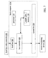
- a local bus 500 may have a dedicated bus controller 510 as shown in the host computer 100 b of FIG. 2, or control of the local and system buses may be integrated into a single bus controller 610 (where information exchanged between processor 110 and memory 120 does not pass through the bus controller) or 620 (where information may be exchanged between processor 110 and memory 120 via the bus controller) as shown in FIGS. 3 and 4, respectively.
- AGP Accelerated Graphics Port
- controller 620 may be implemented using one among the 440BX, 440LX, 440EX, 440MX, 810 , 820 , or 840 chipsets manufactured by Intel Corp. (Santa Clara, Calif.), wherein system bus 300 is a PCI bus.
- a device on system bus 300 (such as RMD 200 a ) cannot directly access a device on local bus 500 .
- the bus controller may be designed to block requests for access to devices on the local bus by devices on system bus 300 . Consequently, in a case where the host computer uses a local bus video controller 400 such as an AGP video card or an embedded AGP video device, remotely monitoring the video output of the host computer with a device on system bus 300 has been considered to be impossible without the support of the operating system of computer 100 c , 100 d . For example, such remote monitoring has been considered to be impossible (1) before an operating system of computer 100 c , 100 d boots and (2) after the operating system has crashed.
- a remote monitoring device on a system bus it is desirable for a remote monitoring device on a system bus to be able to access the memory of a video controller on a local bus during substantially all stages of operation of the host computer, including periods during which the host computer's operating system has not yet loaded, has loaded incorrectly, or has crashed.
- FIG. 1 shows a block diagram of a computer having a system bus and a remote monitoring device.
- FIG. 2 shows a block diagram of a computer having local and system buses and a device on each bus.
- FIG. 3 shows a block diagram of a computer having local and system buses and a device on each bus.
- FIG. 4 shows a block diagram of a computer having local and system buses and a device on each bus
- FIG. 5 shows a flow chart of a method according to an embodiment of the invention.
- FIG. 6 shows a block diagram of a system according to an embodiment of the invention.
- FIG. 7 shows a block diagram of a system according to an embodiment of the invention.
- FIG. 8 shows a flow chart of a method according to an embodiment of the invention.
- FIG. 9 shows a partial flow chart of a method according to an embodiment of the invention.
- FIG. 10 a shows a block diagram of an apparatus according to an embodiment of the invention.
- FIG. 10 b shows a block diagram of an apparatus according to an embodiment of the invention.
- FIG. 11 shows a flow chart of a method according to an embodiment of the invention.
- FIG. 12 shows a flow chart of a method according to an embodiment of the invention.
- FIG. 13 shows a flow chart of a method according to an embodiment of the invention.
- FIG. 14 shows a flow chart of a method according to an embodiment of the invention.
- FIG. 15 shows a flow chart of a method according to an embodiment of the invention.
- FIG. 16 shows a block diagram of a system according to an embodiment of the invention.
- FIG. 17 shows a block diagram of a system according to an embodiment of the invention.
- FIG. 18 shows a flow chart of a method according to an embodiment of the invention.
- FIG. 19 shows a flow chart of a method according to an embodiment of the invention.
- FIG. 20 shows a flow chart of a method according to an embodiment of the invention.
- FIG. 21 shows a flow chart of a method according to an embodiment of the invention.
- FIG. 22 shows a flow chart of a method according to an embodiment of the invention.
- FIG. 23 shows a flow chart of a method according to an embodiment of the invention.
- FIG. 5 shows a flowchart for a method according to an embodiment of the invention.
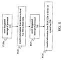
- Event P 110 occurs before an operating system of computer 100 c , 100 d begins to boot.
- This event causes processor 110 to begin to execute a specified sequence of program instructions or ‘code’ for transferring information.
- processor 110 causes information to be transferred from a device on local bus 500 (e.g. local bus video controller (LBVC) 400 ) to a RAM portion 120 a of memory 120 .
- LBVC local bus video controller
- the information is transferred again from RAM 120 a to a device on system bus 300 (e.g. RMD 700 as shown in FIGS. 6 and 7 ).
- a transfer of information from the device on the local bus to the device on the system bus may be initiated or even completed before an operating system of computer 100 c , 100 d begins to boot.
- Event P 110 may occur periodically, with occurrences being separated by a predetermined number of minutes, seconds, or timer clicks, for example. Alternatively, event P 110 may occur according to a schedule: upon completion of a predetermined stage of the Power-On Self Test (POST), for example, or upon completion of the BIOS initialization of computer 100 c , 100 d . Alternatively, event P 110 may occur in response to a condition (such as the detection of an error or fault) or an external signal (such as the reception by RMD 700 of a signal sent by a remote user requesting an update of video information from LBVC 400 ).
- POST Power-On Self Test
- FIG. 6 shows the path of the information from local bus video controller (LBVC) 400 to RMD 700 when the method of FIG. 5 is used with host computer 100 c of FIG. 3 .
- FIG. 7 shows the same path when this method is used with host computer 100 d of FIG. 4 .
- System bus 300 may be a PCI bus or may conform to another established standard such as one of the following:
- MCA Micro Channel Architecture
- IBM Corp. White Plains, N.Y.
- PCI a variant of PCI such as Mini PCI or PCI-X, as defined in Mini PCI 1.0 and PCI-X 1.0, respectively, both available from PCI Special Interest Group;
- VME and VME64 as defined in ANSI/VITA 1-1994 (VITA, Scottsdale, Ariz.), IEEE 1014-1987 (IEEE Standards, Piscataway, N.J.), or ISO/IEC15776 (International Organization for Standardization, Geneva, Switzerland);
- PC/104 and PC/104-Plus, as defined in PC/104 Specification, version 2.3, June 1996 and PC/104-Plus Specification, version 1.1, June 1997, respectively, both available from PC/104 Consortium, Mountain View, Calif.).
- FIG. 8 shows one general implementation of the method of FIG. 5, wherein event P 110 a is the assertion of a designated interrupt of processor 110 , as triggered by event P 110 .
- the vector or table entry associated with the designated interrupt is preconfigured to direct processor 110 to the starting location of the code for performing task P 120 .
- This starting location may be within ROM or RAM of memory 120 or within a memory aboard RMD 700 .
- Configuration of the interrupt may be hard-wired; alternatively, configuration of the interrupt may be achieved, for example, during power-on initialization of computer 100 , system bus 300 , or RMD 700 .
- configuration of the interrupt occurs during a power-on configuration of system bus 300 (which may be, for example, a dynamically configurable bus such as a PCI bus).
- processor 110 loads a block of code from an expansion ROM (or ‘option ROM’) aboard RMD 700 into RAM 120 a (task P 20 in FIG. 9 ).
- Processor 110 then executes at least a portion of the block (task P 40 ), thereby configuring the designated interrupt to point to an interrupt service routine (‘ISR’) within the block of code (task P 60 ).
- ISR interrupt service routine
- processor 110 begins to execute in task P 40 may also cause it to perform other initialization tasks, such as the following:
- Processor 110 may cause a portion of the memory space of RMD 700 to be mapped to a portion of the memory space of processor 110 to enable transfers from one memory space to the other. Processor 110 may also verify that such transfers may be performed successfully. Additionally, in a case where processor 110 executes within a limited memory space during configuration (e.g. in ‘real mode’ as opposed to a ‘protected mode’ of Intel x86 processors), processor 110 may execute instructions as necessary to obtain access to the mapped memory space. (A similar set of instructions may also be executed as a part of the ISR.)
- processor 110 may allocate and/or configure other system resources such as input/output addresses for use by RMD 760 .
- Processor 110 may issue a notification to RMD 700 when configuration of the ISR is completed.
- Loading the ISR code into RAM 120 a allows processor 110 to execute the ISR more rapidly than if it remained resident only in the expansion ROM of RMD 700 .
- the transfer of code from the expansion ROM to RAM 120 a may include a checksum, decryption, and/or decompression operation or the like, such that the form of the information retrieved from the expansion ROM need not literally correspond to the form of the code stored in RAM 120 a.
- the ISR may reside in a ROM aboard computer 100 c , 100 d (e.g. as a part of the BIOS of computer 100 c , 100 d ), or in a ROM aboard RMD 700 (e.g. as a part of the expansion ROM), rather than within RAM 120 a.
- the ISR may reside in RAM aboard RMD 700 , having been copied from ROM during initialization of computer 100 c, 100 d, system bus 300 , or RMD 700 .
- the code for configuring the ISR (if required) may be executed from ROM or RAM and may be a part of the BIOS of computer 100 c , 100 d or of an expansion ROM aboard RMD 700 .
- processor 110 then performs task P 120 by executing further instructions within the ISR, thereby transferring this portion of the information from RAM 120 a to RMD 700 (e.g. to an onboard RAM or communications port or buffer) or to another device on system bus 300 .
- FIG, 10 a shows an apparatus 700 a according to an embodiment of the invention, including expansion ROM 720 and bus connector 730 which connects to system bus 300 .
- processor 110 may have many other tasks to perform, it is desirable to effect the information transfer with a minimal load on processor 110 .
- processor 110 interrupts a processor 710 a board RMD 700 b (as shown in FIG. 10 b ) (task P 125 of FIG. 11) and returns from the ISR (possibly after write-protecting the area of RAM 120 a that stores the portion of the information).
- Processor 710 then executes an ISR associated with the interrupt asserted by processor 110 , thereby transferring the information from buffer area 120 a to RMD 700 a over system bus 300 (task P 130 ) and via bus connector 730 .
- Processor 110 is thus released to do other work while processor 710 completes the transfer to another storage area (e.g. within RMD 700 a ) and/or to the remote user (e.g. by packetizing the data and forwarding it over a network or telephone line connection).
- bus controllers 610 and 620 may prevent a device on system bus 300 from obtaining the information directly from video controller 400 , this implementation bypasses such restrictions by taking advantage of the features that (1) processor 110 has access to devices on local bus 500 and (2) processors 110 and 710 may both access at least some part of memory 120 .
- RAM 120 a By designating a portion within RAM 120 a to be the common area, the implementations described above allow processor 110 to perform the transfer to the common area as quickly as possible. However, note that practice of the invention is not limited to the use of RAM 120 a (or even to the use of a portion of memory 120 ) as the area of common access.
- tasks P 120 and/or P 130 may be executed several times for each block of information (e.g. video frame) transferred.
- buffer area 120 a is smaller than the area required to store a video frame, so that tasks P 120 and P 130 must be executed more than once to transfer a complete video frame.
- processor 710 determines whether a complete video frame has been transferred by, for example, (1) checking to see how many bytes have been transferred so far or (2) checking to see whether processor 110 (or another device such as bus controller 610 or 620 ) has indicated that the entire frame was transferred into buffer area 120 a .
- Task P 140 may also be performed by processor 110 and/or another device such as bus controller 610 or 620 .
- FIG. 13 shows a method for a case in which buffer area 120 a is large enough to accommodate an entire block, but processor 710 does not transfer all of the data in area 120 a at once (e.g. because of storage limits within RMD 700 , or because of a slow connection to the remote user).
- processor 710 determines whether the transfer from area 120 a is complete by, for example, checking to see how many bytes have been transferred so far. In some implementations, it may be necessary to interrupt processor 710 again before executing task P 130 if the test in task P 150 fails.
- FIG. 14 shows a method for a case in which the capacity limitations discussed with reference to FIGS. 12 and 13 both apply.
- processor 710 constructs a message in a shared memory area and asserts the designated interrupt of processor 110 .
- the corresponding ISR causes processor 110 to access the message and respond accordingly.
- this message may have one of the following forms:
- Get video mode indicate whether screen is in text or graphics mode and/or return number of colors in palette (or pixel depth in bits)
- Get screen size indicate number of columns and rows (for text mode) or number of horizontal and vertical pixels (for graphics mode)
- Get cursor position indicate screen coordinates of cursor
- Get video memory contents return information from video buffer of LBVC 400 .
- Processor 110 constructs a reply to the message and posts it in the shared memory space. This message may comprise an identifying header followed by the forwarded information. Processor 110 then asserts the designated interrupt of processor 710 to indicate that a message is waiting. Processor 710 retrieves the message for local storage and/or delivery to a remote user. This procedure may be repeated until the desired block of information (along with any ancillary information) has been transferred to RMD 700 . For example, successive messages sent by processor 710 may request successive portions of the desired block of information.
- FIG. 15 shows a flowchart for a method according to an alternative embodiment of the invention.
- the transfer of information from the device on local bus 500 to the device on system bus 300 is accomplished by processor 110 in one action (task P 122 ).
- FIGS. 16 and 17 show the path of information from LBVC 400 to RMD 700 when this method is used with host computer 100 c of FIG. 3 (wherein the transferred information passes through processor 110 ) and host computer 100 d of FIG. 4 (wherein the transferred information does not pass through processor 110 ), respectively.
- FIG. 18 shows one general implementation of this method, wherein event P 110 a is the assertion event described above.
- FIG. 19 shows a particular implementation wherein RMD 700 has a shared memory area (i.e. at least some of the memory of RMD 700 is mapped to a window in the main memory space of processor 110 ).
- processor 110 transfers the information from the device on local bus 500 to the shared memory area.
- processor 110 asserts an interrupt of processor 710 (task P 127 ).
- task P 132 processor 710 executes a transfer of the information out of the shared memory area.
- the transfer of task P 132 may comprise a transfer into another portion of the memory of RMD 700 (e.g. to make room for another incoming transfer), wherein future processing tasks may include storing the information, forwarding it to the remote user, etc.
- the transfer of task P 132 may also comprise transmission of the information to the remote user directly from the shared memory area.
- FIG. 20 shows a method for a case in which the shared memory area is too small to accommodate an entire block, such that tasks P 124 and P 132 must be executed more than once to transfer an entire block.
- processor 710 (or another device such as processor 110 or bus controller 610 or 620 ) evaluates the status of the transfer as described above with respect to task P 140 .
- FIG. 21 shows a method for a case in which the shared memory area is large enough to accommodate an entire block, but processor 710 does not transfer all of the information from it at once (e.g. because of bandwidth limitations).
- processor 710 determines whether the transfer from the shared memory area is complete by, for example, checking to see how many bytes have been transferred so far. In some implementations, it may be necessary to interrupt processor 710 again before executing task P 132 if the test in task P 152 fails.
- FIG. 22 shows a method for a case in which the capacity limitations discussed with reference to FIGS. 20 and 21 both apply.
- processor 710 may construct and post the message before asserting the interrupt of processor 110 .
- processor 110 may interrupt processor 710 to indicate that the requested information (or some portion of it) is available in the shared memory area.
- processor 110 is an Intel x86 processor, for example, the BIOS configuration may execute in ‘real mode,’ with processor 110 having access to only a limited portion of its total memory space. Loading the operating system may cause the processor to enter ‘protected mode,’ thereby obtaining a wider access to the memory space but also losing access to the existing ‘real-mode’ interrupt vector configuration. Although the interrupts may then be reconfigured to execute similar ISRs in ‘protected mode,’ a malfunction of the operating system may cause this configuration to become unavailable as well (e.g. by causing the interrupts to be masked). It is desirable for remote monitoring capabilities to remain available during loading of the operating system as well as during and after a malfunctioning of the operating system.
- a method according to an embodiment of the invention continues to support requests for cross-bus transfers both during and after loading of the operating system (i.e. after processor 110 enters ‘protected mode,’ event P 210 of FIG. 23) by modifying the ISR for a non-maskable interrupt (NMI) of processor 110 (task P 220 ).
- NMI non-maskable interrupt
- the NMI which may be a feature of both Intel and non-Intel processors, is distinguished from other interrupts in that the NMI remains operational when another interrupt line or lines of the processor are masked.
- Computer 100 c may use the NMI to indicate certain system conditions, such as a memory parity error.
- a device desiring to initiate a cross-bus transfer will record a transfer request indication in an area that is accessible to processor 110 (task P 230 ). For example, a message constructed by processor 710 as described above may serve as such an indication.
- processor 110 Upon assertion of the NMI (event P 240 ), processor 110 begins to execute the modified NMI ISR. In executing this code, processor 110 tests whether a transfer request indication is present (task P 250 ). If no such indication is found, then it is assumed that the NMI was asserted in response to a system condition such as a parity error, and processor 110 is directed to perform tasks relating to the original NMI ISR (task P 270 ). Note that it may be possible to perform task P 270 simply by directing processor 110 to the starting location of the original NMI ISR. If a transfer request indication is found, then processor 110 is directed to perform tasks relating to the requested transfer, as described above (task P 260 ). Note that although these tasks may be similar or even identical to those described above (e.g. with respect to tasks P 120 and/or P 130 ), it may not be possible to direct processor 110 to execute the same code in order to perform those tasks, as that code may be incompatible with a present mode of processor 110 .
- code for modifying an ISR of a NMI of processor 110 is packaged as a device driver.
- This driver is loaded by an operating system of computer 100 c into a RAM portion of memory 120 (e.g. from a ROM, from a hard drive within computer 100 c , or over a network connection) for execution by processor 110 .
- processor 110 causes the ISR of the NMI to be modified (task P 220 ).
- processor 110 It is desirable to restore the availability of cross-bus transfers as quickly as possible after processor 110 enters ‘protected mode’ (event P 210 ). Such availability may be obtained by causing processor 110 to modify the NMI ISR as early as possible in the boot process of the operating system. Different particular implementations may be practiced to obtain such early modification depending on which operating system is booting.
- processor 110 For a case in which the operating system is Windows NTTM (Microsoft Corp., Redmond, Wash.), it is possible to cause processor 110 to load and execute the device driver during the phase immediately following firmware execution by declaring the driver to be a ‘system bus extender.’ This declaration may be achieved by configuring the operating system's registry in computer 100 c to assign the driver a ⁇ Services ⁇ DriverName ⁇ Start value of SERVICE_BOOT_START (0x0).
- early loading and execution of the configuration driver may be obtained by listing the driver as the first file in startup and in the configuration files of the operating system. In this case it may be necessary to list the driver as a disk driver during linking and to avoid the use of any external libraries during compilation of the driver (i.e. to call only those functions that are native to the operating system).
- a system, method, and apparatus allows cross-bus transfers of information to be conducted (e.g. as needed to perform remote monitoring of the video output of a computer) regardless of whether the operating system has loaded correctly or at all.
- Such capabilities as the remote selection of an operating system for booting and the remote execution of command-line repair tools and the like are thereby supported.
- the foregoing description of the preferred embodiments is provided to enable any person skilled in the art to make or use the present invention.
- Various modifications to these embodiments are possible, and the generic principles presented herein may be applied to other embodiments as well.
- the invention may be implemented in part or in whole as a hard-wired circuit, as a circuit configuration fabricated into an application-specific integrated circuit, or as a firmware program loaded into non-volatile storage or a software program loaded from or into a data storage medium as machine-readable code, such code being instructions executable by an array of logic elements such as a microprocessor or other digital signal processing unit.
- processors 110 and/or 710 may also cause these transfers by sending data which identify the source and destination addresses to another device (such as bus controller 610 or 620 ) along with a command to effect the transfer.
- the invention is described principally in terms of allowing remote access to video memory on a local device, the invention may be practiced in many other situations wherein it is desired for a first device peripheral to a host processor to access information stored in or available at a second device peripheral to the host processor, and wherein a direct access of the second device by the first device is prevented or restricted.
- the present invention is not intended to be limited to the embodiments shown above but rather is to be accorded the widest scope consistent with the principles and novel features disclosed in any fashion herein.
Abstract
Description
Claims (25)
Priority Applications (1)
| Application Number | Priority Date | Filing Date | Title |
|---|---|---|---|
| US09/520,802 US6754759B1 (en) | 2000-03-08 | 2000-03-08 | Transfer of information between devices on different buses |
Applications Claiming Priority (1)
| Application Number | Priority Date | Filing Date | Title |
|---|---|---|---|
| US09/520,802 US6754759B1 (en) | 2000-03-08 | 2000-03-08 | Transfer of information between devices on different buses |
Publications (1)
| Publication Number | Publication Date |
|---|---|
| US6754759B1 true US6754759B1 (en) | 2004-06-22 |
Family
ID=32469719
Family Applications (1)
| Application Number | Title | Priority Date | Filing Date |
|---|---|---|---|
| US09/520,802 Expired - Lifetime US6754759B1 (en) | 2000-03-08 | 2000-03-08 | Transfer of information between devices on different buses |
Country Status (1)
| Country | Link |
|---|---|
| US (1) | US6754759B1 (en) |
Cited By (7)
| Publication number | Priority date | Publication date | Assignee | Title |
|---|---|---|---|---|
| US20060031619A1 (en) * | 2004-08-05 | 2006-02-09 | Nguyen Hung T | Asynchronous system bus adapter for a computer system having a hierarchical bus structure |
| US20060035686A1 (en) * | 1999-07-23 | 2006-02-16 | Kyocera Corporation | Mobile telephone |
| US20060242351A1 (en) * | 2005-04-20 | 2006-10-26 | Kavian Nasrollah A | Method and apparatus for loading instructions into high memory |
| US20070055807A1 (en) * | 2005-08-31 | 2007-03-08 | Ati Technologies Inc. | Methods and apparatus for translating messages in a computing system |
| US20100235618A1 (en) * | 2009-03-11 | 2010-09-16 | Harman Becker Automotive Systems Gmbh | Start-up of computing systems |
| US20180074843A1 (en) * | 2011-03-31 | 2018-03-15 | P4tents1, LLC | System, method, and computer program product for linking devices for coordinated operation |
| US10960760B2 (en) * | 2016-03-07 | 2021-03-30 | Lg Electronics Inc. | Vehicle control device mounted in vehicle and control method thereof |
Citations (13)
| Publication number | Priority date | Publication date | Assignee | Title |
|---|---|---|---|---|
| US5339395A (en) * | 1992-09-17 | 1994-08-16 | Delco Electronics Corporation | Interface circuit for interfacing a peripheral device with a microprocessor operating in either a synchronous or an asynchronous mode |
| JPH07309064A (en) * | 1994-05-16 | 1995-11-28 | New Oji Paper Co Ltd | Thermosensible recording paper |
| US5710892A (en) * | 1995-07-19 | 1998-01-20 | International Business Machines Corporation | System and method for asynchronous dual bus conversion using double state machines |
| US5715410A (en) * | 1994-12-12 | 1998-02-03 | Samsung Electronics Co., Ltd. | Interface circuit for supporting PCMCIA cards in an X-terminal |
| US5732212A (en) * | 1992-10-23 | 1998-03-24 | Fox Network Systems, Inc. | System and method for remote monitoring and operation of personal computers |
| US5732268A (en) * | 1996-02-26 | 1998-03-24 | Award Software International | Extended BIOS adapted to establish remote communication for diagnostics and repair |
| US5835760A (en) * | 1995-10-13 | 1998-11-10 | Texas Instruments Incorporated | Method and arrangement for providing BIOS to a host computer |
| US5887164A (en) * | 1997-06-06 | 1999-03-23 | National Instruments Corporation | System and method for enabling a target computer to use storage resources of a host computer |
| US5911051A (en) * | 1996-03-29 | 1999-06-08 | Intel Corporation | High-throughput interconnect allowing bus transactions based on partial access requests |
| US6023507A (en) * | 1997-03-17 | 2000-02-08 | Sun Microsystems, Inc. | Automatic remote computer monitoring system |
| US6108492A (en) * | 1997-02-14 | 2000-08-22 | Toshiba America Information Systems | Remote monitoring system |
| US6195734B1 (en) * | 1997-07-02 | 2001-02-27 | Micron Technology, Inc. | System for implementing a graphic address remapping table as a virtual register file in system memory |
| US6311245B1 (en) * | 1998-06-05 | 2001-10-30 | Micron Technology, Inc. | Method for time multiplexing a low-speed and a high-speed bus over shared signal lines of a physical bus |
-
2000
- 2000-03-08 US US09/520,802 patent/US6754759B1/en not_active Expired - Lifetime
Patent Citations (13)
| Publication number | Priority date | Publication date | Assignee | Title |
|---|---|---|---|---|
| US5339395A (en) * | 1992-09-17 | 1994-08-16 | Delco Electronics Corporation | Interface circuit for interfacing a peripheral device with a microprocessor operating in either a synchronous or an asynchronous mode |
| US5732212A (en) * | 1992-10-23 | 1998-03-24 | Fox Network Systems, Inc. | System and method for remote monitoring and operation of personal computers |
| JPH07309064A (en) * | 1994-05-16 | 1995-11-28 | New Oji Paper Co Ltd | Thermosensible recording paper |
| US5715410A (en) * | 1994-12-12 | 1998-02-03 | Samsung Electronics Co., Ltd. | Interface circuit for supporting PCMCIA cards in an X-terminal |
| US5710892A (en) * | 1995-07-19 | 1998-01-20 | International Business Machines Corporation | System and method for asynchronous dual bus conversion using double state machines |
| US5835760A (en) * | 1995-10-13 | 1998-11-10 | Texas Instruments Incorporated | Method and arrangement for providing BIOS to a host computer |
| US5732268A (en) * | 1996-02-26 | 1998-03-24 | Award Software International | Extended BIOS adapted to establish remote communication for diagnostics and repair |
| US5911051A (en) * | 1996-03-29 | 1999-06-08 | Intel Corporation | High-throughput interconnect allowing bus transactions based on partial access requests |
| US6108492A (en) * | 1997-02-14 | 2000-08-22 | Toshiba America Information Systems | Remote monitoring system |
| US6023507A (en) * | 1997-03-17 | 2000-02-08 | Sun Microsystems, Inc. | Automatic remote computer monitoring system |
| US5887164A (en) * | 1997-06-06 | 1999-03-23 | National Instruments Corporation | System and method for enabling a target computer to use storage resources of a host computer |
| US6195734B1 (en) * | 1997-07-02 | 2001-02-27 | Micron Technology, Inc. | System for implementing a graphic address remapping table as a virtual register file in system memory |
| US6311245B1 (en) * | 1998-06-05 | 2001-10-30 | Micron Technology, Inc. | Method for time multiplexing a low-speed and a high-speed bus over shared signal lines of a physical bus |
Non-Patent Citations (96)
| Title |
|---|
| "6. System Configuration and A.G.P. Initialization," Revision 2.0, Oct. 3, Corporation, pp. 243-259. |
| "Accelerated Graphics Port Interface Specification," Revision 2.0, Intel Corporation, May 4, 1998, 29 pp. |
| "Developer Kit Tips Application Note" PCI Local Bus, Applied Micro Circuits Corporation, Revision 1, Jan. 20, 1998, 7 pp. |
| "PCI Local Bus Specification Revision 2.1 vs. Revision 2.0," AP-753 Application Note, Intel Corporation, Mar. 1997, 8 pp. |
| "The Expansion ROM Option Application Note," Applied Micro Circuits Corporation Revision 1, Jun. 2, 1998, 9 pp. |
| "VT82C597/VT82C597AT," VIA Technologies Inc., Revision 1.0, Oct. 3, 1997, pp. include Table of Contents, p. 4 and 11-17. |
| American Megatrends MegaRAC(TM) Hardware Guide Preliminary DRAFT MAN-780, Dec. 18, 1998, 24 pp. (pp. i-vi and 1-18). |
| American Megatrends MegaRAC™ Hardware Guide Preliminary DRAFT MAN-780, Dec. 18, 1998, 24 pp. (pp. i-vi and 1-18). |
| Compaq Computer Corporation, Phoenix Technologies Ltd., Intel Corporation, "BIOS Boot Specification, Version 1.01," Jan. 11, 1996, 46 pp. |
| http://agent.microsoft.com/hwdev/BUSBIOS/optROM.htm, "Windows 2000 and Unreported Memory from Option ROMS," accessed and printed Feb. 10, 2000, 2 pp. |
| http://avocetsystems.com/softaid/articles/aintrp.shtml, "Interrupt Predictability," accessed and printed Feb. 14, 2000, 6 pp. |
| http://developer.intel.com/design/bridge/, "PCI-to-PCI Bridge Products," accessed and printed Aug. 5, 1999, 2 pp. |
| http://developer.intel.com/technology/ago/tutorial/chapt_6.htm, "What This Means for Software Developers, Accelerated Graphics Port Technology," AGP Tutorial: Chapter 6, accessed and printed Aug. 24, 2000, 3 pp. |
| http://developer.intel.com/technology/agp/tutorial/chapt_2.htm, "3D Graphics on Next Generation PCs, Accelerated graphics Port Technology," AGP Tutorial: Chapter 2, accessed and printed Aug. 24, 2000, 2 pp.* * |
| http://developer.intel.com/technology/agp/tutorial/chapt_3.htm, "AGP Data Transfers Modes, Accelerated Graphics Port Technology," AGP Tutorial: Chapter 3, accessed and printed Aug. 24, 2000, 1 p.* * |
| http://developer.intel.com/technology/agp/tutorial/chapt_4.htm, "AGP Memory Mapping, Accelerated Graphics Port Technology," AGP Tutorial: Chapter 4, accessed and printed Dec. 8, 2000, 2 pp. |
| http://developer.intel.com/technology/agp/tutorial/chapt_5.htm, "A Summary of AGP's Benefits, Accelerated Graphics Port Technology," AGP Tutorial: Chapter 5, accessed and printed Aug. 24, 2000, 1 p. |
| http://developer.intel.com/techology/agp/tutorial/chapt_1.htm, "3D Graphics on Current Generation PCs, Accelerated graphics Port Technology," AGP Tutorial: Chapter 1, accessed and printed Aug. 24, 2000, 3 pp.* * |
| http://gateway.centre.com/faqpnpp.htm, "Product Help Desk Ethernet Adapter Cards," accessed and printed Aug. 27, 1999, pp. 1 and 2. |
| http://han-en-jana.rc.tudelft.nl/interupt/out-2200.htm, "Diskless Boot Hook (Start Cassette Basic," accessed and printed Feb. 11, 2000, 1 p. |
| http://heaven.hamline.edu/LDP/LDP/tkl/dd/pci.html, "PCI," Chapter 6, accessed and printed Aug. 27, 1999, 14 pp. |
| http://members.hyperlink.net.au/~chart/pci.htm, "PCI Information," accessed and printed Aug. 27, 1999, 1 p. |
| http://members.hyperlink.net.au/~chart/whatpci.htm, "What is PCI anyhow, and why write about it," accessed and printed Aug. 27, 1999, 3 pp. |
| http://members.hyperlink.net.au/˜chart/pci.htm, "PCI Information," accessed and printed Aug. 27, 1999, 1 p. |
| http://members.hyperlink.net.au/˜chart/whatpci.htm, "What is PCI anyhow, and why write about it," accessed and printed Aug. 27, 1999, 3 pp. |
| http://msdn.microsoft.com/library.ddkdoc/ntddk/native/ddk/pg/src/101initl_7.htm, "1.2.5 Controlling Driver Load Order," accessed and printed Feb. 7, 2000, 3 pp. |
| http://msdn.microsoft.com/library/ddkdoc/ntddk/native/ddk/kg/src/16issues_31.htm, "16.8.1.2 Load-control Sets for NT Drivers," accessed and printed Feb. 7, 2000, 3 pp. |
| http://msdn.microsoft.com/library/ddkdoc/ntddk/native/ddk/pg/src/101initl_1.htm, "1.1 Loading the System," accessed and printed Feb. 14, 2000, 2 pp. |
| http://msdn.microsoft.com/library/spec/S1CE5B.HTM, "2.2 Plug and Play ISA Card Support," accessed and printed Feb. 8, 2000, 2 pp. |
| http://msdn.microsoft.com/library/specs/S1C973.HTM, "2.0 System BIOS Installation," accessed and printed Feb. 8, 2000, 1 p. |
| http://msdn.microsoft.com/library/specs/S1C979.HTM, "3.0 Option ROM Support," accessed and printed Feb. 8, 2000, 1 p. |
| http://msdn.microsoft.com/library/specs/S1CE58.HTM, "1.3 Elements of the Plug and Play BIOS architecture," accessed and printed Feb. 8, 2000, 1 p. |
| http://msdn.microsoft.com/library/specs/S1CE59.HTM, "1.4 Installation Structure," accessed and printed Feb. 8, 2000, 1 p. |
| http://msdn.microsoft.com/library/specs/S1CE5A.HTM, "2.1 System BIOS POST Requirements," accessed and printed Feb. 8, 2000, 4 pp. |
| http://msdn.microsoft.com/library/specs/S1CE5C.HTM, "2.3 BIOS POST Option ROM initialization," accessed and printed Feb. 8, 2000, 2 pp. |
| http://msdn.microsoft.com/library/specs/S1CE5D.HTM, "2.4 Transferring Control to the Operating System," accessed and printed Feb. 8, 2000, 1 p. |
| http://msdn.microsoft.com/library/specs/S1CE5E.HTM, "2.5 POST Execution flow," accessed and printed Feb. 8, 2000, 2 pp. |
| http://msdn.microsoft.com/library/specs/S1CE5F.HTM, "3.1 Option ROM Header," accessed and printed Feb. 8, 2000, 2 pp. |
| http://msdn.microsoft.com/library/specs/s1ce61.htm, "3.3 Option ROM Initialization," accessed and printed Feb. 8, 2000, 2 pp. |
| http://msdn.microsoft.com/library/specs/S1CE62.HTM, "3.4 Option ROM Initialization flow," accessed and printed Feb. 8, 2000, 1 p. |
| http://msdn.microsoft.com/library/specs/S1CE63.HTM, "3.5 ISA Option ROMs and Resource Mapping," accessed and printed Feb, 8, 2000, 1 p. |
| http://msdn.microsoft.com/library/specs/S1CE6D.HTM, "Genetic Option ROM Headers," Appendix A, accessed and printed Feb. 9, 2000, 2 pp. |
| http://msdn.microsoft.com/library/specs/S1CE6E.HTM, "Appendix B: Device Driver Initialization Model," accessed and printed Feb. 8, 2000, 2 pp. |
| http://stommel.tamu.edu/~baum/linux/LDP/LDP/tkl/dd/pci.html, "Chapter 6, PCI," accessed and printed Dec. 27, 1999, 15 pp. |
| http://stommel.tamu.edu/˜baum/linux/LDP/LDP/tkl/dd/pci.html, "Chapter 6, PCI," accessed and printed Dec. 27, 1999, 15 pp. |
| http://support.intel.com/support/chipsets/PC1001.HTM, "Efficient use of PCI," accessed and printed Aug. 24, 2000, 11 pp. |
| http://support.microsoft.com/support/kb/articles/Q152/0/44.asp, "HOWTO: Create a PCI Device Driver for Windows NT," accessed and printed Feb. 7, 2000, 4 pp. |
| http://support.premiopc.com/vedge/440bx_.htm, "Virtual Edge-Intel 440BX AGPset Block Diagram," accessed and printed Aug. 27, 1999, 1 p. |
| http://support.premiopc.com/vedge/440bx_.htm, "Virtual Edge—Intel 440BX AGPset Block Diagram," accessed and printed Aug. 27, 1999, 1 p. |
| http://users.erols.com/jhuffake/ref/dod2post.html, "Tech Talk: System POST," Bob Sherman, last update Jun. 28, 1999, 3 pp., accessed and printed Feb. 10, 2000. |
| http://www.adaptec.com/technology/whitepapers/pcibus.html, "PCI Bus Overview," accessed and printed Aug. 11, 1999, 10 pp.* * |
| http://www.ami.com/ami/server-solutions.html, Remote Server Assistance, last accessed Aug. 10, 1999, 1 p. |
| http://www.ami.com/utilities/s780spec.html, MegaRAC(TM) (Series 780) Remote Server Management Motherboard, last accessed Aug. 10, 1999, 4 pp. |
| http://www.ami.com/utilities/s780spec.html, MegaRAC™ (Series 780) Remote Server Management Motherboard, last accessed Aug. 10, 1999, 4 pp. |
| http://www.byte.com/art/9402/sec10/art2.htm, "Inside the PCI Local Bus," dated Feb. 1994, accessed and printed Dec. 30, 1999, 9 pp. |
| http://www.diplan.de/~martin/intel/pnp/bio1_30.htm, Compaq Computer Corp., Pheonix Technologies Ltd., and Intel Corporation, "Plug and Play BIOS Specification, Sec. 3," ver. 1.0A, May 5, 1994, 8 pp., accessed and printed Feb. 9, 2000. |
| http://www.diplan.de/˜martin/intel/pnp/bio1_30.htm, Compaq Computer Corp., Pheonix Technologies Ltd., and Intel Corporation, "Plug and Play BIOS Specification, Sec. 3," ver. 1.0A, May 5, 1994, 8 pp., accessed and printed Feb. 9, 2000. |
| http://www.execpc.com/~geezer/os/pm.htm, "Protected Mode Tutorial," accessed and printed Dec. 29, 1999, 5 pp. |
| http://www.execpc.com/˜geezer/os/pm.htm, "Protected Mode Tutorial," accessed and printed Dec. 29, 1999, 5 pp. |
| http://www.firmware.com/support/bios/shadow.htm, "What is BIOS Shadowing?," accessed and printed Feb. 10, 2000, 2 pp. |
| http://www.han.de/~gero/netboot/archive/msg01592.html, "Re: v0.9.0d Error in PCI image.rom generation.," accessed and printed Aug. 24, 2000, 3 pp.* * |
| http://www.han.de/˜gero/netboot/archive/msg01592.html, "Re: v0.9.0d Error in PCI image.rom generation.," accessed and printed Aug. 24, 2000, 3 pp.* |
| http://www.horizon-tech.fr/articles/other/pci/pci.htm, "Application Note, Plug and Play Operation of the PCI Local Bus," accessed and printed Feb. 8, 2000, 6 pp. + Figs. 1 and 2 (. . . /pci/image1.jpg, . . . /pci/image2.jpg). |
| http://www.intel.com.tw/support/desktopmgmt/pxepdk.htm, Wired for Management (WfM), Intel (R) Preboot Execution Environment (PXE) PDK, accessed and printed Feb. 10, 2000, 3 pp. |
| http://www.intel.com/network/demos/LANDesk_srvr_mgr_demo/em.htm, "LANDesk Server Manager Pro-The Intel (R) Remote Management Card," accessed and printed Aug. 5, 1999, 1 p. |
| http://www.intel.com/network/demos/LANDesk_srvr_mgr_demo/em.htm, "LANDesk Server Manager Pro—The Intel (R) Remote Management Card," accessed and printed Aug. 5, 1999, 1 p. |
| http://www.intel.com/network/demos/LANDesk_srvr_mgr_demo/em_2.htm, "LANDesk Server Manager Pro-The Intel (R) Remote Management Card 2," accessed and printed Aug. 24, 2000, 1 p. |
| http://www.intel.com/network/demos/LANDesk_srvr_mgr_demo/em_2.htm, "LANDesk Server Manager Pro—The Intel (R) Remote Management Card 2," accessed and printed Aug. 24, 2000, 1 p. |
| http://www.intel.com/pc-supp/platform/agfxport/ecr.htm, "Accelerated Graphics Port Interface Specification," accessed and printed Aug. 5, 1999, 1 p. |
| http://www.internals.com/articles/protmode/interrups.htm, "Interrupts and Exceptions," Yariv Kaplan, accessed and printed Aug. 12, 1999, 7 pp. |
| http://www.internals.com/articles/protmode/introduction.htm, "Introduction to Protected-Mode," Yariv Kaplan, accessed and printed Aug. 12, 1999, 3 pp. |
| http://www.internals.com/articles/protmode/protmode.htm, "Protected-Mode Memory Management," Yariv Kaplan, accessed and printed Aug. 12, 1999, 8 pp. |
| http://www.internals.com/articles/protmode/realmode.htm, "Real-Mode Memory Management," Yariv Kaplan, accessed and printed Aug. 12, 1999, 3 pp. |
| http://www.Isilogic.com/graphics/5_9h3.gif, "Figure 3. MPEG-2/AC-3 Host Port on PCI," accessed and printed Aug. 11, 1999, 1 p. |
| http://www.Isilogic.com/graphics/5_9h5.gif, "Figure 5. Bus Utilization model," accessed and printed Aug. 11, 1999, 1 p. |
| http://www.Isilogic.com/graphics5_9h4.gif, "Figure 4. Standalone PCI Solution," accessed and printed Aug. 11, 1999, 1 p. |
| http://www.mega-tokyo.com/os/os-faq-pci.html, "Operating Systems FAC::PCI," accessed and printed Dec. 29, 1999, 3 pp. |
| http://www.microsoft.com/hwdev/busbios/pciirq.htm, "PCI IRQ Routing Table Specification," accessed and printed Aug. 27, 1999. 6 pp. |
| http://www.microsoft.com/hwdev/pci/vgacard.htm, "Configuring PCI-to-PCI Bridges with VGA Cards," accessed and printed Aug. 24, 1999, 4 pp. |
| http://www.mkdata.dk/click/module2d.htm, "An Illustrated Guide to chip sets," accessed and printed Aug. 27, 1999, 1 p.* * |
| http://www.onement.com/2fast4u/avmbkgrd.html, "Bus Mastering," accessed and printed Aug. 11, 1999, 1 p. |
| http://www.pcisig.com/reflector/msg00267.html, "Re: PCI and Expansion ROM," accessed and printed Feb. 9, 2000, 3 pp. |
| http://www.pcisig.com/reflector/msg00367.html, "Re: PCI I/O Space Consumption Limitation," accessed and printed Feb. 9, 2000, 3 pp. |
| http://www.sanders.com/hpc/ArchGuide/Elements/Commune/PC.html, "PC Buses13 PCI," accessed and printed Aug. 27, 1999, 1 p. |
| http://www.tomshardware.co.kr/agp-perf.html, "Does AGP Really Improve Performance?," Bert McComas, accessed and printed Aug. 5, 1999, 6 pp. |
| http://www.tyan.com/support/html/agp.html, "AGP FAQ," accessed and printed Aug. 5, 1999, 1 p. |
| http://www.viking.delmar.edu/courses/CIS312J/Ebook/wrh05.htm, "BIOS Extensions" (2 pp.), ROM Shadowing (1 p.), "Structure" (2 pp.), Winn L. Rosch Hardware Bible, Electronic Edition, Chap. 5, accessed and printed Feb. 9, 2000. |
| http://www.xeon.com/ial/wfm/wfm20/design/pxedt/index.htm, "Desktop Preboot Execution Environment (PXE) for Desktop Systems," accessed and printed Feb. 10, 2000, 2 pp. |
| http://www8.zdnet.com/pcmag/pclabs/nettools/1719/bench3.html, Jeffrey Witt, "Server Management, Servicing Servers", last accessed Aug. 15, 1999, 3 pp. |
| http:www.comymedia.com/intel/serverman.html, "Intel LANDesk(R) Server Manager Products," last accessed Aug. 15, 1999, 7 pp. |
| http:www.comymedia.com/intel/serverman.html, "Intel LANDesk® Server Manager Products," last accessed Aug. 15, 1999, 7 pp. |
| Intel(R) LANDesk(R) Server Manager 6 Administrator's Guide, Intel Corporation, 1999, 75 pp. |
| Intel(R) LANDesk(R) Server Manager 6 Installation Guide, Intel Corporation, 1999, 47 pp. |
| Intel, "System Address Map," 82443BX Host Bridge Datasheet, pp. 5-27 through 5-36. |
| Intel® LANDesk® Server Manager 6 Administrator's Guide, Intel Corporation, 1999, 75 pp. |
| Intel® LANDesk® Server Manager 6 Installation Guide, Intel Corporation, 1999, 47 pp. |
Cited By (12)
| Publication number | Priority date | Publication date | Assignee | Title |
|---|---|---|---|---|
| US20060035686A1 (en) * | 1999-07-23 | 2006-02-16 | Kyocera Corporation | Mobile telephone |
| US7742789B1 (en) * | 1999-07-23 | 2010-06-22 | Kyocera Corporation | Mobile telephone |
| US7747287B2 (en) | 1999-07-23 | 2010-06-29 | Kyocera Corporation | Mobile telephone |
| US20060031619A1 (en) * | 2004-08-05 | 2006-02-09 | Nguyen Hung T | Asynchronous system bus adapter for a computer system having a hierarchical bus structure |
| US7167939B2 (en) * | 2004-08-05 | 2007-01-23 | Lsi Logic Corporation | Asynchronous system bus adapter for a computer system having a hierarchical bus structure |
| US20060242351A1 (en) * | 2005-04-20 | 2006-10-26 | Kavian Nasrollah A | Method and apparatus for loading instructions into high memory |
| US20070055807A1 (en) * | 2005-08-31 | 2007-03-08 | Ati Technologies Inc. | Methods and apparatus for translating messages in a computing system |
| US7805560B2 (en) * | 2005-08-31 | 2010-09-28 | Ati Technologies Inc. | Methods and apparatus for translating messages in a computing system |
| US20100235618A1 (en) * | 2009-03-11 | 2010-09-16 | Harman Becker Automotive Systems Gmbh | Start-up of computing systems |
| US8621193B2 (en) * | 2009-03-11 | 2013-12-31 | Harman Becker Automotive Systems Gmbh | Booting a computer system at start-up by transferring a first part of instructions using a second bus and transferring a second part of instructions using a first bus where the second bus is configured to transfer instructions at a faster rate than the first bus |
| US20180074843A1 (en) * | 2011-03-31 | 2018-03-15 | P4tents1, LLC | System, method, and computer program product for linking devices for coordinated operation |
| US10960760B2 (en) * | 2016-03-07 | 2021-03-30 | Lg Electronics Inc. | Vehicle control device mounted in vehicle and control method thereof |
Similar Documents
| Publication | Publication Date | Title |
|---|---|---|
| KR100620216B1 (en) | Network Enhanced BIOS Enabling Remote Management of a Computer Without a Functioning Operating System | |
| US6370606B1 (en) | System and method for simulating hardware interrupts in a multiprocessor computer system | |
| US6438711B2 (en) | Method and apparatus for performing field diagnostics on a computer system | |
| US6487608B2 (en) | Method for automatically configuring network interface card and capable of randomizing a media access controller address of the network interface card | |
| US6920553B1 (en) | Method and apparatus for reading initial boot instructions from a bootable device connected to the USB port of a computer system | |
| US6560641B1 (en) | System, method, and adapter card for remote console emulation including remote control of a peripheral device | |
| US7461247B2 (en) | Method for transitioning control of a peripheral device from a first device driver to a second device driver during operating system initialization | |
| US5872968A (en) | Data processing network with boot process using multiple servers | |
| US8566644B1 (en) | System and method for debugging a target computer using SMBus | |
| US6629157B1 (en) | System and method for virtualizing the configuration space of PCI devices in a processing system | |
| US6189114B1 (en) | Data processing system diagnostics | |
| US6321279B1 (en) | System for implementing intelligent I/O processing in a multi-processor system by redirecting I/O messages to a target central processor selected from the multi-processor system | |
| US9052916B2 (en) | System ROM with an embedded disk image | |
| US7478141B2 (en) | Accessing firmware of a remote computer system using a remote firmware interface | |
| US20070169076A1 (en) | Methods and systems for updating a BIOS image | |
| US20030200428A1 (en) | Method and system for booting a client computer system over a network | |
| US6006344A (en) | Keyboard controlled diagnostic system | |
| US6615288B1 (en) | Generating system management interrupt in response to usb controller signal and processing interrupt routine in upper most level of system memory | |
| US20040153811A1 (en) | Computer system equipped with a BIOS debugging card | |
| US7231512B2 (en) | Technique for reconstituting a pre-boot firmware environment after launch of an operating system | |
| US5968174A (en) | Method and apparatus for implementing a 32-bit operating system which supports 16-bit code | |
| US5537597A (en) | Method and apparatus for supporting real mode card services clients with a protected mode card services implementation | |
| US6754759B1 (en) | Transfer of information between devices on different buses | |
| US20040199600A1 (en) | Method and apparatus for program installation in a modular network | |
| US5321830A (en) | Reset method when adaptor module is faulty and computer system executing same |
Legal Events
| Date | Code | Title | Description |
|---|---|---|---|
| AS | Assignment |
Owner name: INTEL CORPORATION, CALIFORNIA Free format text: ASSIGNMENT OF ASSIGNORS INTEREST;ASSIGNORS:COOK, COLIN N.B.;UNICE, WARREN K.;REEL/FRAME:010903/0933 Effective date: 20000706 |
|
| STCF | Information on status: patent grant |
Free format text: PATENTED CASE |
|
| FEPP | Fee payment procedure |
Free format text: PAYER NUMBER DE-ASSIGNED (ORIGINAL EVENT CODE: RMPN); ENTITY STATUS OF PATENT OWNER: LARGE ENTITY Free format text: PAYOR NUMBER ASSIGNED (ORIGINAL EVENT CODE: ASPN); ENTITY STATUS OF PATENT OWNER: LARGE ENTITY |
|
| FPAY | Fee payment |
Year of fee payment: 4 |
|
| REMI | Maintenance fee reminder mailed | ||
| FPAY | Fee payment |
Year of fee payment: 8 |
|
| REMI | Maintenance fee reminder mailed | ||
| AS | Assignment |
Owner name: BEIJING XIAOMI MOBILE SOFTWARE CO., LTD., CHINA Free format text: ASSIGNMENT OF ASSIGNORS INTEREST;ASSIGNOR:INTEL CORPORATION;REEL/FRAME:037733/0440 Effective date: 20160204 |
|
| FPAY | Fee payment |
Year of fee payment: 12 |
|
| SULP | Surcharge for late payment |
Year of fee payment: 11 |