US6757248B1 - Performance enhancement of transmission control protocol (TCP) for wireless network applications - Google Patents
Performance enhancement of transmission control protocol (TCP) for wireless network applications Download PDFInfo
- Publication number
- US6757248B1 US6757248B1 US09/594,443 US59444300A US6757248B1 US 6757248 B1 US6757248 B1 US 6757248B1 US 59444300 A US59444300 A US 59444300A US 6757248 B1 US6757248 B1 US 6757248B1
- Authority
- US
- United States
- Prior art keywords
- network
- congestion
- packet
- cwnd
- ssthresh
- Prior art date
- Legal status (The legal status is an assumption and is not a legal conclusion. Google has not performed a legal analysis and makes no representation as to the accuracy of the status listed.)
- Expired - Fee Related, expires
Links
Images


Classifications
-
- H—ELECTRICITY
- H04—ELECTRIC COMMUNICATION TECHNIQUE
- H04W—WIRELESS COMMUNICATION NETWORKS
- H04W28/00—Network traffic management; Network resource management
- H04W28/02—Traffic management, e.g. flow control or congestion control
- H04W28/10—Flow control between communication endpoints
-
- H—ELECTRICITY
- H04—ELECTRIC COMMUNICATION TECHNIQUE
- H04L—TRANSMISSION OF DIGITAL INFORMATION, e.g. TELEGRAPHIC COMMUNICATION
- H04L1/00—Arrangements for detecting or preventing errors in the information received
- H04L1/12—Arrangements for detecting or preventing errors in the information received by using return channel
- H04L1/16—Arrangements for detecting or preventing errors in the information received by using return channel in which the return channel carries supervisory signals, e.g. repetition request signals
- H04L1/18—Automatic repetition systems, e.g. Van Duuren systems
- H04L1/1829—Arrangements specially adapted for the receiver end
- H04L1/1858—Transmission or retransmission of more than one copy of acknowledgement message
-
- H—ELECTRICITY
- H04—ELECTRIC COMMUNICATION TECHNIQUE
- H04L—TRANSMISSION OF DIGITAL INFORMATION, e.g. TELEGRAPHIC COMMUNICATION
- H04L1/00—Arrangements for detecting or preventing errors in the information received
- H04L1/12—Arrangements for detecting or preventing errors in the information received by using return channel
- H04L1/16—Arrangements for detecting or preventing errors in the information received by using return channel in which the return channel carries supervisory signals, e.g. repetition request signals
- H04L1/18—Automatic repetition systems, e.g. Van Duuren systems
- H04L1/1867—Arrangements specially adapted for the transmitter end
- H04L1/187—Details of sliding window management
-
- H—ELECTRICITY
- H04—ELECTRIC COMMUNICATION TECHNIQUE
- H04L—TRANSMISSION OF DIGITAL INFORMATION, e.g. TELEGRAPHIC COMMUNICATION
- H04L1/00—Arrangements for detecting or preventing errors in the information received
- H04L1/12—Arrangements for detecting or preventing errors in the information received by using return channel
- H04L1/16—Arrangements for detecting or preventing errors in the information received by using return channel in which the return channel carries supervisory signals, e.g. repetition request signals
- H04L1/18—Automatic repetition systems, e.g. Van Duuren systems
- H04L1/1867—Arrangements specially adapted for the transmitter end
- H04L1/188—Time-out mechanisms
-
- H—ELECTRICITY
- H04—ELECTRIC COMMUNICATION TECHNIQUE
- H04L—TRANSMISSION OF DIGITAL INFORMATION, e.g. TELEGRAPHIC COMMUNICATION
- H04L47/00—Traffic control in data switching networks
- H04L47/10—Flow control; Congestion control
-
- H—ELECTRICITY
- H04—ELECTRIC COMMUNICATION TECHNIQUE
- H04L—TRANSMISSION OF DIGITAL INFORMATION, e.g. TELEGRAPHIC COMMUNICATION
- H04L47/00—Traffic control in data switching networks
- H04L47/10—Flow control; Congestion control
- H04L47/18—End to end
-
- H—ELECTRICITY
- H04—ELECTRIC COMMUNICATION TECHNIQUE
- H04L—TRANSMISSION OF DIGITAL INFORMATION, e.g. TELEGRAPHIC COMMUNICATION
- H04L47/00—Traffic control in data switching networks
- H04L47/10—Flow control; Congestion control
- H04L47/19—Flow control; Congestion control at layers above the network layer
- H04L47/193—Flow control; Congestion control at layers above the network layer at the transport layer, e.g. TCP related
-
- H—ELECTRICITY
- H04—ELECTRIC COMMUNICATION TECHNIQUE
- H04L—TRANSMISSION OF DIGITAL INFORMATION, e.g. TELEGRAPHIC COMMUNICATION
- H04L47/00—Traffic control in data switching networks
- H04L47/10—Flow control; Congestion control
- H04L47/26—Flow control; Congestion control using explicit feedback to the source, e.g. choke packets
- H04L47/263—Rate modification at the source after receiving feedback
-
- H—ELECTRICITY
- H04—ELECTRIC COMMUNICATION TECHNIQUE
- H04L—TRANSMISSION OF DIGITAL INFORMATION, e.g. TELEGRAPHIC COMMUNICATION
- H04L47/00—Traffic control in data switching networks
- H04L47/10—Flow control; Congestion control
- H04L47/27—Evaluation or update of window size, e.g. using information derived from acknowledged [ACK] packets
-
- H—ELECTRICITY
- H04—ELECTRIC COMMUNICATION TECHNIQUE
- H04L—TRANSMISSION OF DIGITAL INFORMATION, e.g. TELEGRAPHIC COMMUNICATION
- H04L47/00—Traffic control in data switching networks
- H04L47/10—Flow control; Congestion control
- H04L47/37—Slow start
-
- H—ELECTRICITY
- H04—ELECTRIC COMMUNICATION TECHNIQUE
- H04L—TRANSMISSION OF DIGITAL INFORMATION, e.g. TELEGRAPHIC COMMUNICATION
- H04L69/00—Network arrangements, protocols or services independent of the application payload and not provided for in the other groups of this subclass
- H04L69/16—Implementation or adaptation of Internet protocol [IP], of transmission control protocol [TCP] or of user datagram protocol [UDP]
- H04L69/163—In-band adaptation of TCP data exchange; In-band control procedures
-
- H—ELECTRICITY
- H04—ELECTRIC COMMUNICATION TECHNIQUE
- H04L—TRANSMISSION OF DIGITAL INFORMATION, e.g. TELEGRAPHIC COMMUNICATION
- H04L69/00—Network arrangements, protocols or services independent of the application payload and not provided for in the other groups of this subclass
- H04L69/16—Implementation or adaptation of Internet protocol [IP], of transmission control protocol [TCP] or of user datagram protocol [UDP]
- H04L69/168—Implementation or adaptation of Internet protocol [IP], of transmission control protocol [TCP] or of user datagram protocol [UDP] specially adapted for link layer protocols, e.g. asynchronous transfer mode [ATM], synchronous optical network [SONET] or point-to-point protocol [PPP]
-
- H—ELECTRICITY
- H04—ELECTRIC COMMUNICATION TECHNIQUE
- H04W—WIRELESS COMMUNICATION NETWORKS
- H04W28/00—Network traffic management; Network resource management
- H04W28/02—Traffic management, e.g. flow control or congestion control
- H04W28/0231—Traffic management, e.g. flow control or congestion control based on communication conditions
- H04W28/0242—Determining whether packet losses are due to overload or to deterioration of radio communication conditions
-
- H—ELECTRICITY
- H04—ELECTRIC COMMUNICATION TECHNIQUE
- H04W—WIRELESS COMMUNICATION NETWORKS
- H04W8/00—Network data management
- H04W8/02—Processing of mobility data, e.g. registration information at HLR [Home Location Register] or VLR [Visitor Location Register]; Transfer of mobility data, e.g. between HLR, VLR or external networks
- H04W8/04—Registration at HLR or HSS [Home Subscriber Server]
-
- H—ELECTRICITY
- H04—ELECTRIC COMMUNICATION TECHNIQUE
- H04L—TRANSMISSION OF DIGITAL INFORMATION, e.g. TELEGRAPHIC COMMUNICATION
- H04L69/00—Network arrangements, protocols or services independent of the application payload and not provided for in the other groups of this subclass
- H04L69/16—Implementation or adaptation of Internet protocol [IP], of transmission control protocol [TCP] or of user datagram protocol [UDP]
-
- H—ELECTRICITY
- H04—ELECTRIC COMMUNICATION TECHNIQUE
- H04W—WIRELESS COMMUNICATION NETWORKS
- H04W80/00—Wireless network protocols or protocol adaptations to wireless operation
Definitions
- the present invention relates to a serial of transfer protocols for high-quality and high-speed data transfer in data networks, especially wireless or mobile networks, and more particularly, relates to performance enhancement of Transmission Control Protocol (TCP) for wireless network applications.
- TCP Transmission Control Protocol
- a data network is a collection of network devices, or nodes interconnected by point-to-point links.
- Communication links may be wired (i.e., optical fiber) or wireless (i.e., infrared or radio-frequency) for supporting a number of logical point-to-point channels.
- Each channel may be a bi-directional communication path for allowing commands and message data to flow between two network devices or nodes within the data network.
- Network devices or nodes may be categorized as either end systems or routers, which are also known as intermediate systems or communication gateways. End systems may include PCs, workstations, mainframes, file servers, storage devices and other types of computers.
- Router may include a number of communication links for forwarding data arriving over one link onto another link for transmission to an end system or another router.
- end systems both send data to other end stations on the data network and receive data sent by other end systems on the data network.
- an end system serves as a sender of data, it is referred to as a source for that data; whereas, when such an end station serves as a receiver of data, it is referred to as a destination for the data.
- end systems may act as both sources and destinations depending upon whether they are sending or receiving data.
- the end system sends data in the form of messages over a communication link to a router for transferring the messages to an end system or another router.
- Each message may comprise a sequence of information bits.
- the messages sent over the data network are not sent as a continuous, uninterrupted stream of bits. Rather, they are divided up into smaller blocks of information called packets, which are then transmitted individually.
- Each packet has a predetermined maximum length.
- a packet also includes a header field which contains control information such as format, identifiers which indicate what portion of the message is contained in the packet, the source of the packet and the intended destination of the packet.
- One important design objective in data networks is controlling the flow of packets so that such packets may not be transmitted at a faster rate than they can be processed by the routers through which the packets may pass or by the destinations.
- the source may flood the destination if it transmits packets faster than they can be processed by the destination.
- numerous routers and alternative communication paths between the end systems the likelihood of problems from excess communication traffic is significantly greater. This becomes especially true as the number of active end systems on the network increases and if communication speeds of the equipment within the network are mismatched.
- a mismatch may exist if, for example, a router cannot transfer packets as fast as they are being sent to it by the source.
- a mismatch may also exist between the speed at which the link can transmit packets, namely the link speed, and the rate at which the router can transfer packets.
- achieving an acceptable traffic control also becomes more difficult.
- TCP Transmission Control Protocol
- RRC 793, September 1981 Transmission Control Protocol
- TCP Transmission Control Protocol
- both the routers and the end systems are provided with buffer memory to handle overloads. Arriving traffic which exceeds the processing rate of the device is temporarily stored in the buffer memory until the device can process it. Buffers offer a satisfactory solution to excess traffic problems only if the overload is transitory. If the overload persists for too long, the buffers may become full after which the additional packets are rejected or destroyed.
- the other mechanism deals with the allocation of resources at the destination, such as memory and processing.
- the destination sets a limit on the rate at which each source sending data to the destination may transmit that data.
- the sources and the destinations coordinate the transfer of data by an exchange of messages containing requests and acknowledgments.
- the source Before the source starts sending packets, it will send a request to the destination seeking permission to begin transmission.
- the destination sends a message containing an identification of the number of packets the source may dispatch toward the destination without, further authorization. This number is commonly referred to as the window size.
- the source then proceeds to transmit the authorized number of packets toward the destination and waits for the destination to verify their receipt.
- the destination After the destination successfully receives a packet, it sends a message back to the source containing an acknowledgment indicating the successful receipt of the packet and, in some cases, authorizing the source to send another packet. In this way, the number of packets on the network traveling from the source toward the destination will never be more than the authorized window size.
- Congestion control typically involves feedback which signals the onset of congestion and instructs end systems to decrease the rate at which they initiate transmission of packets.
- TCP congestion control algorithms are described in RFC 2581 and RFC 2582, which employs both Fast Retransmit algorithm and Fast Recovery algorithm (FRFR), also known as Reno algorithms. These two algorithms rely on counting “duplicate ACKs”—TCP immediate acknowledge sent from the destination in response to each additional data segment received following missing data.
- FRFR Fast Retransmit and Fast Recovery (FRFR) algorithms are intended to preserve self-clock during recovery from a lost data segment.
- FRFR Fast Retransmit algorithm uses duplicate ACKs to detect the loss of a data segment. When three duplicate ACKs are detected, TCP assumes that a data segment has been lost and retransmit the lost packet, without waiting for a retransmission timer to expire.
- the Fast Recovery algorithm attempts to estimate how much data remains outstanding in the network by counting duplicate ACKs.
- the Fast Recovery algorithm artificially inflates the congestion window “CWND” (i.e., TCP state variable that limits the amount of data a TCP source can send) on each duplicate ACK that is received, causing new data to be transmitted as the congestion window “CWND” becomes large enough.
- CWND congestion window
- Fast Recovery algorithm allows one (halved) window of new data to be transmitted following a Fast Retransmit. After the lost packet has been acknowledged, the congestion window “CWND” should be reduced and the TCP source would come into the state of congestion avoidance.
- TCP assumption is generally false—most lost packets are due to errors that occur in the transmission of packets over error-prone media such as infrared or radio-frequency links, as opposed to network congestion.
- BER Bit Error Rate
- TCP mistakenly assumes that the network is congested and dramatically reduces its transmission of old and new packets. For example, whenever a packet is lost, TCP automatically resets its current window and threshold, then traps in the state of Slow-Start frequently, which may sharply degrade the throughput of connection.
- BER Bit Error Rate
- a new algorithm is needed to distinguish congestion packets loss from individual packet loss due to Bit Error Rate (BER), to reject coming into Slow-Start and facilitate fast recovery when lost packets are due to Bit Error Rate (BER), and to reduce its sending speed as normal TCP upon occurrence of congestion so as to improve the throughput of connection in wireless and/or mobile networks.
- BER Bit Error Rate
- BER Bit Error Rate
- various embodiments of the present invention are directed to a new recovery mechanism known as Fast Recovery Plus (FR+) algorithms and associated method, for wireless and/or mobile network applications to distinguish congestion packets loss from individual packet loss due to Bit Error Rate (BER), to advance fast data recovery when lost packets are due to Bit Error Rate (BER), and to reduce its sending speed as normal TCP upon occurrence of congestion so as to improve the throughput of connection while effectively avoiding network congestion in a TCP/IP packet-switched network such as wireless and/or mobile networks.
- FR+ enhanced Recovery Plus
- Such enhanced Recovery Plus (FR+) algorithms may be installed or integrated into a host and/or a computer readable medium for use in a host for promoting fast data recovery while effectively controlling network congestion in packet-switched networks, especially wireless or mobile networks.
- a method of flow control and congestion avoidance congestion in a network comprises the steps of: transmitting, at a source node, data packets to a destination node, via at least an intermediate node; receiving, at the destination node, data packets transmitted from the source node, via the intermediate node, and generating a duplicate ACK back to the source node to inform the source node that a data packet was received out-of-order in the network and serves as an indication that a data packet has been lost; upon receipt of a designated number of duplicate ACKs, at the source node, determining that a data packet has been lost; initializing a counter, at the source node, and recording a congestion window CWND, a slow start threshold Ssthresh, and a maximal sequence number SN that has been sent into the network; upon receipt of a next duplicate ACK, at the source node, recording its acknowledged sequence number ACK_SN; determining, at the source node, if the acknowledged sequence number ACK
- the slow start threshold Ssthresh is set to no more than Max(FlightSize/2, 2*SMSS), wherein said FlightSize indicates the amount of outstanding data in the network, and said SMSS indicates the size of a largest data segment that can be transmitted.
- the counter is set to record the number of times of packet re-transmission invoked by the duplicate ACKs.
- packet loss is due to the transmission error, when the value of the counter is no more than a pre-defined packet threshold indicating the threshold of packet loss. Otherwise, packet loss is due to congestion in which case the congestion window CWND is reduced to halve, and a slow start threshold Ssthresh is reduced to the congestion window to slow a transmission rate to avoid congestion in the network.
- a data network for wireless and/or mobile network applications may comprise a source node for transmitting data packets; a destination node for receiving the data packets from the source node and generating duplicate ACKs when the arrival of data packets is out-of-order; and at least one intermediate node disposed between said source node and said destination node; wherein said source node includes a Fast Recovery Plus (FR+) algorithm which, when activated upon receipt duplicate ACKs, performs the following: initializing a counter and recording a congestion window CWND, a slow start threshold Ssthresh, and a current maximal sequence number SN that has been sent into the network; upon receipt of a next duplicate ACK, recording its acknowledged sequence number ACK_SN; determining if the acknowledged sequence number ACK_SN is no less than a recorded sequence number SN; if the acknowledged sequence number ACK_SN is no less than the recorded sequence number SN, incrementing the counter, and re-transmitting a lost packet;
- FR+ Fast Recovery Plus
- the present invention relates to a computer readable medium having an enhanced Fast Recovery Plus (FR+) algorithm stored therein for wireless network applications, when executed by a host system, performs the following: upon receipt of duplicate ACKs from a remote system, determining that a data packet has been lost; initializing a counter, and recording a congestion window CWND, a slow start threshold Ssthresh, and a maximal sequence number SN that has been sent into the network; upon receipt of a next.
- FR+ enhanced Fast Recovery Plus
- FIG. 1 illustrates a data packet for use in a packet-switched network according to an embodiment of the present invention
- FIG. 2 illustrates an example packet-switched network using an existing congestion control mechanism installed therein for congestion control and avoidance in the network
- FIG. 3 illustrates an example packet-switched network using an advanced Fast Recovery Plus (FR+) mechanism installed therein for congestion control and avoidance in the network according to an embodiment of the present invention
- FR+ Advanced Fast Recovery Plus
- FIG. 4 is a flowchart representation of an advanced Fast Recovery Plus (FR+) mechanism according to an embodiment of the present invention
- FIG. 5 illustrates one preferred usage implementation of a packet-switched network including an advanced Fast Recovery Plus (FR+) mechanism installed therein for controlling congestion according to an embodiment of the present invention
- FR+ Fast Recovery Plus
- FIG. 6 illustrates another preferred usage implementation of a packet-switched network including an advanced Fast Recovery Plus (FR+) mechanism installed therein for controlling congestion according to an embodiment of the present invention
- FR+ Fast Recovery Plus
- FIG. 7 illustrates a single connection network for comparison simulations of an example Reno (FRFR) algorithm and an advanced Fast Recovery Plus (FR+) algorithm;
- FRFR Reno
- FR+ advanced Fast Recovery Plus
- FIGS. 8A-8B illustrate simulation results in terms of the congestion window “CWND” of the single connection network executing the Reno (FRFR) algorithm and the advanced Fast Recovery Plus (FR+) algorithm in low-speed links without congestion;
- FIG. 9 illustrates simulation results in terms of the TCP Sequence Number “SN” of the single connection network executing the Reno (FRFR) algorithm and the advanced Fast Recovery Plus (FR+) algorithm in low-speed links without congestion;
- FIGS. 10A-10B illustrate simulation results in terms of the Utilization of Link of the single connection network executing the Reno (FRFR) algorithm and the advanced Fast Recovery Plus (FR+) algorithm in low-speed links without congestion;
- FRFR Reno
- FR+ advanced Fast Recovery Plus
- FIGS. 11A-11B illustrate simulation results in terms of the congestion window “CWND” of the single connection network executing the Reno (FRFR) algorithm and the advanced Fast Recovery Plus (FR+) algorithm in high-speed links without congestion;
- FRFR Reno
- FR+ advanced Fast Recovery Plus
- FIG. 12 illustrates simulation results in terms of the TCP Sequence Number “SN” of the single connection network executing the Reno (FRFR) algorithm and the advanced Fast Recovery Plus (FR+) algorithm in high-speed links without congestion;
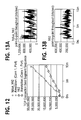
- FIGS. 13A-13B illustrate simulation results in terms of the Utilization of Link of the single connection network executing the Reno (FRFR) algorithm and the advanced Fast Recovery Plus (FR+) algorithm in high-speed links without congestion;
- FRFR Reno
- FR+ advanced Fast Recovery Plus
- FIGS. 14A-14B illustrate simulation results in terms of the congestion window “CWND” of the single connection network executing the Reno (FRFR) algorithm and the advanced Fast Recovery Plus (FR+) algorithm in high-speed links with congestion;
- FRFR Reno
- FR+ advanced Fast Recovery Plus
- FIG. 15 illustrates simulation results in terms of the TCP Sequence Number “SN” of the single connection network executing the Reno (FRFR) algorithm and the advanced Fast Recovery Plus (FR+) algorithm in high-speed links with congestion;
- FIG. 16 illustrates simulation results in terms of TCP data overflow of the single connection network executing the Reno (FRFR) algorithm and the advanced Fast Recovery Plus (FR+) algorithm in high-speed links with congestion;
- FIGS. 17A-17B illustrate simulation results in terms of the Utilization of Link of the single connection network executing the Reno (FRFR) algorithm and the advanced Fast Recovery Plus (FR+) algorithm in high-speed links with congestion;
- FRFR Reno
- FR+ advanced Fast Recovery Plus
- FIGS. 18A-18B illustrate simulation results in terms of the Queue Size in the Router of the single connection network executing the Reno (FRFR) algorithm and the advanced Fast Recovery Plus (FR+) algorithm in high-speed links with congestion;
- FRFR Reno
- FR+ advanced Fast Recovery Plus
- FIG. 19 illustrates a multiple connection network for comparison simulations of an example Reno (FRFR) algorithm and an advanced Fast Recovery Plus (FR+) algorithm;
- FRFR Reno
- FR+ advanced Fast Recovery Plus
- FIG. 20 illustrates simulation results in terms of the TCP Sequence Number “SN” of all connections executing the Reno (FRFR) algorithm and the advanced Fast Recovery Plus (FR+) algorithm in high-speed links without congestion;
- FIGS. 21A-21B illustrate simulation results in terms of the congestion window “CWND” of all connections executing the Reno (FRFR) algorithm and the advanced Fast Recovery Plus (FR+) algorithm in high-speed links without congestion;
- FIGS. 22A-22B illustrate simulation results in terms of the Utilization of Link of all connections executing the Reno (FRFR) algorithm and the advanced Fast Recovery Plus (FR+) algorithm in high-speed links without congestion;
- FIG. 20 illustrates simulation results in terms of the TCP Sequence Number “SN” of all connections executing the Reno (FRFR) algorithm and the advanced Fast Recovery Plus (FR+) algorithm in high-speed links without congestion;
- FIGS. 21A-21B illustrate simulation results in terms of the congestion window “CWND” of one connection in the multiple connection network executing the Reno (FRFR) algorithm and the advanced Fast Recovery Plus (FR+) algorithm in high-speed links without congestion;
- FRFR Reno
- FR+ advanced Fast Recovery Plus
- FIGS. 22A-22B illustrate simulation results in terms of the Utilization of Link of one connection in the multiple connection network executing the Reno (FRFR) algorithm and the advanced Fast Recovery Plus (FR+) algorithm in high-speed links without congestion;
- FRFR Reno
- FR+ advanced Fast Recovery Plus
- FIGS. 23A-23B illustrate simulation results in terms of the congestion window “CWND” of all connections in the multiple connection network executing the Reno (FRFR) algorithm and the advanced Fast Recovery Plus (FR+) algorithm in high-speed links with congestion;
- FRFR Reno
- FR+ advanced Fast Recovery Plus
- FIGS. 24A-24B illustrate simulation results in terms of the TCP Sequence Number “SN” of one connection of the multiple connection network executing the Reno (FRFR) algorithm and the advanced Fast Recovery Plus (FR+) algorithm in high-speed links with congestion;
- FRFR Reno
- FR+ advanced Fast Recovery Plus
- FIGS. 25A-25B illustrate simulation results in terms of the Utilization of Link of one connection in the multiple connection network executing the Reno (FRFR) algorithm and the advanced Fast Recovery Plus (FR+) algorithm in high-speed links with congestion;
- FRFR Reno
- FR+ advanced Fast Recovery Plus
- FIGS. 26A-26B illustrate simulation results in terms of the Queue Size in the Router of the multiple connection network executing the Reno (FRFR) algorithm and the advanced Fast Recovery Plus (FR+) algorithm in high-speed links with congestion; and
- FIG. 27 illustrates simulation results in terms of data overflows of the multiple connection network executing the Reno (FRFR) algorithm and the advanced Fast Recovery Plus (FR+) algorithm in high-speed links with congestion.
- FRFR Reno
- FR+ advanced Fast Recovery Plus
- the present invention is applicable for use with all types of data networks, including packet-switched networks, interconnected systems of such networks and transmission protocols used for data transfer between host systems in such networks.
- TCP Transmission Control Protocol
- IP Transmission Control Protocol
- a data packet 100 for use in a packet-switched network according to an embodiment of the present invention is illustrated.
- a data packet 100 consists of a segment of data 140 and a small header 120 prepended to the data 140 .
- the header 120 may contain an Internet Protocol (IP) header 120 A and a Transmission Control Protocol (TCP) header 120 B which follows the IP header 120 A for supplying information specific to the TCP protocol.
- IP Internet Protocol
- TCP Transmission Control Protocol
- the IP header 120 A may contain several information fields, including, for example, Internet Protocol (IP) addresses fields (Internet address, generally consisting of a network identifier and a host identifier), a version field used to specify which version of the IP is represented in the IP packet (for example, IP Version 4 and IP Version 6), a type of service field used to specify how the IP packet is to be handled in IP-based networks which offer various service qualities, and a header checksum field used to verify transmission error.
- IP Internet Protocol
- FIG. 1B illustrates an example TCP header format of the TCP header 120 B of a data packet 100 , as described by the classical TCP specification [RFC 793, September 1981].
- TCP header 120 B may include, for example, Source Port Number, Destination Port Number, Sequence Number, Acknowledgment Number, Data Offset, Reserved Field for future use, Control Bits including URG (Urgent Pointer field significant), ACK (Acknowledgment field significant), PSH (Push Function), RST (Reset the connection), SYN (Synchronize sequence numbers) and FIN (no more data from sender), Window, Checksum, Urgent Pointer, Variable Options, and Padding.
- Acknowledgment Number may contain 32 bits for indicating the value of the next sequence number the TCP source is expecting to receive.
- Data Offset may contain 4 bits for indicating where the data begins.
- the Window may contain 16 bits for indicating the number of data octets beginning with the one indicated in the acknowledgment field which the TCP sender of the data segment is willing to accept.
- the Checksum may contain 16 bits for indicating the complement sum of all 16 bit words in the header and text.
- the Urgent Pointer may contain 16 bits for indicating the sequence number of the octet following the urgent data.
- the variable options may contain a multiple of 8 bits in length and may be included in the checksum.
- the variable header padding may be used to ensure that the TCP header ends and data begins on a 32 bit boundary.
- FIG. 2 illustrates an example packet-switched network 200 having existing flow control and congestion control mechanisms installed therein for flow control and congestion avoidance in the network.
- the packet-switched network 200 includes, for example, a source node 210 , a destination node 220 , and an intermediate node 230 .
- IP bandwidth-limited links 202 and 204 may be utilized to connect the source node 210 to the destination node 220 .
- the IP bandwidth-limited links 202 and 204 may represent a low bandwidth link such as, for example, an integrated service digital service (ISDN) link and a modem link that connect to the source node 210 and the destination node 220 .
- ISDN integrated service digital service
- the TCP/IP bandwidth-limited links 202 and 204 may include an TCP/IP network of an Internet Service Provider (ISP), an Internet and different source and destination networks, including, for example, a packet-switched network that provides linkage between the source node 210 and the destination node 220 .
- ISP Internet Service Provider
- packet-switched network that provides linkage between the source node 210 and the destination node 220 .
- the source node 210 and the destination node 220 are known as end systems which may correspond to PCs, workstations, mainframes, file servers, storage devices and other types of computers.
- the intermediate node 230 may correspond to a router or a communication gateway containing a number of communication links for forwarding data arriving over one link onto another link for transmission to an end system or another router.
- the source node 210 may include, but not limited to, a host 212 and a TCP module 214 .
- the destination node 220 may include, but not limited to, a host 222 and a TCP module 224 . Both the TCP modules 214 and 224 may be installed independently from respective host, or may be installed in respective host. Alternatively, the TCP modules 214 and 224 may reside in respective network interface card (NIC) (not shown) installed in the source node 210 and destination node 220 , respectively.
- NIC network interface card
- the host 212 In the source node 210 , the host 212 generates data which is forwarded to the TCP module 114 .
- the TCP module 214 of the source node 210 transforms incoming data from host 212 into IP data packets 100 and injects the data packets 100 into the IP-based network 200 .
- the rate of that data packets are injected into the TCP/IP network 200 and the outward flow of data packets 100 are controlled and managed by the TCP module 214 to avoid congestion and to limit bandwidth usage of IP packets in the TCP/IP network 200 .
- the TCP/IP network 200 accepts incoming data packets 100 and forwards the same to the destination node 220 according to the information contained in the IP header 120 .
- the TCP module 224 of the destination node 220 receives the data packets 100 from the TCP/IP network 200 , transforms the same into data and forwards the data to the host 222 .
- the intermediate node 230 may or may not include mechanisms for the detection of incipient congestion. Either embodiment, such an intermediate node 230 may operate to drop data packets when there is a queue overflow. Packet drops serve as the method of informing the source node 210 of congestion in the TCP/IP network 200 . When a packet is dropped from the intermediate node 230 , a data segment arriving at the destination node 220 will be out-of-order.
- the destination node 220 Upon receipt of an out-of-order data segment, the destination node 220 generates an immediate acknowledge (a duplicate ACK) to inform the source node 210 that a data packet was received out-of-order and what sequence number is expected.
- an immediate acknowledge (a duplicate ACK) to inform the source node 210 that a data packet was received out-of-order and what sequence number is expected.
- TCP flow control and congestion control mechanisms such as Fast Retransmit and Fast Recovery algorithms, known as Reno algorithms as described in RFC 2581 and RFC 2582, are typically installed, for example, in the TCP module 214 of the source node 210 to control data flow and congestion avoidance in the TCP/IP network 200 .
- Fast Retransmit algorithm and Fast Recovery algorithm are usually implemented together, and are invoked in response to the duplicate ACK—TCP immediate acknowledge sent from the destination node 220 in response to each additional data segment received following missing data.
- These two algorithms rely on counting “duplicate ACKs” and are intended to preserve self-clock during recovery from a lost data segment.
- Fast Retransmit algorithm uses duplicate ACKs to detect the loss of a data segment.
- the TCP module 214 of the source node 210 assumes that a data segment has been lost and retransmit the lost packet to the destination node 220 , without waiting for a retransmission timer to expire.
- the Fast Recovery algorithm attempts to estimate how much data remains outstanding in the network by counting duplicate ACKs.
- the Fast Recovery algorithm artificially inflates the congestion window “CWND” (i.e., TCP state variable that limits the amount of data the TCP module 214 of a source node 210 can send) on each duplicate ACK that is received, causing new data to be transmitted as the congestion window “CWND” becomes large enough.
- CWND congestion window
- Fast Recovery algorithm allows one (halved) window of new data to be transmitted following a Fast Retransmit. After the lost packet has been acknowledged, the congestion window “CWND” should be reduced and the TCP module 214 of the source node 210 would come into the state of congestion avoidance.
- BER Bit Error Rate
- the TCP module 214 of the source node 210 mistakenly assumes that the network is congested and dramatically reduces its transmission of old and new packets. For example, whenever a packet is lost, TCP module 214 of the source node 210 automatically resets its current window and threshold, then comes into the state of Slow-Start frequently, which may sharply degrade the throughput of connection.
- the packet-switched network 300 includes the same components, such as a source node 310 , a destination node 320 , and at least one intermediate node 330 .
- the intermediate node 330 may operate to drop data packets, as described with reference to FIG. 2, when there is a queue overflow. Such packet drops may serve as the method of informing the source node 310 of congestion in the TCP/IP network 300 .
- enhanced TCP modules 314 and 324 of the respective source node 310 and destination node 320 contain a new and efficient Fast Recovery Plus (FR+) mechanism provided to distinguish congestion packets loss from individual packet loss due to Bit Error Rate (BER), to reject coming into Slow-Start and facilitate fast recovery when lost packets are due to Bit Error Rate (BER), and to reduce its sending speed as normal TCP upon occurrence of congestion so as to improve the throughput of connection and TCP performance in high-speed packet-switched networks, especially wireless or mobile networks.
- FR+ Fast Recovery Plus
- Such enhancements to the TCP modules 314 and 324 of respective source node 310 and destination node 320 may be implemented by a Fast Recovery Plus (FR+) algorithm or a software module configured to distinguish congestion packet loss from individual packet loss due to Bit Error Rate (BER) and advance fast recovery when lost packets are due to BER.
- the Fast Recovery Plus (FR+) algorithm implementation may rely on the use of standard programming methods using high level program languages, such as C, C++ and Visual Basic, and a general purpose (host) processor.
- the Fast Recovery Plus (FR+) algorithm is independent from, but is adaptable to all existing TCP flow control and congestion control mechanisms.
- Such Fast Recovery Plus (FR+) algorithm may be integrated into an existing operating system (OS) of a host processor (i.e., end node including a source node and a destination node) and/or a computer readable medium for use in a host processor (i.e., end node) for congestion control and avoidance in the TCP/IP network 300 .
- OS operating system
- the Fast Recovery Plus (FR+) algorithm may also be integrated into, or as part of, existing TCP flow control and congestion avoidance algorithms as described with reference to FIG. 2 .
- the Fast Recovery Plus (FR+) algorithm implementation may, however, operate based on the following assumptions:
- the throughput of an individual data flow may range from less than 2,400 bps to more than 10 Mbps.
- the TCP module 314 of the source node 310 finds a packet loss, the TCP module 314 records the number of packet loss in the next congestion window “CWND”. If the number is no more than the threshold (which may be set as “1”), packet loss will be treated as sporadic loss due to sporadic transmission error. Otherwise, such packet loss will be treated as paroxysmal loss due to congestion.
- the threshold which may be set as “1”
- the TCP module 314 of the source node 310 need not reduce its congestion window “CWND” to slow down the sending speed (transmission rate). Therefore, the value of slow start threshold “SSTHRESH” can be quickly recovered before packet loss, which is significantly different from the existing TCP flow control and congestion control mechanisms, such as Fast Retransmit/Fast Recovery algorithms, also known as Reno algorithms as described in RFC 2581 and RFC 2582. This way the TCP module 314 of the source node 310 can recover to its original speed very quickly.
- the TCP module 314 of the source node 310 acts as normal TCP, that is, the TCP module 314 of the source node 310 resets its current congestion window and threshold, and comes into the state of Slow-Start.
- the TCP module 314 of the source node 310 acts as normal TCP to avoid increasing the burden of the TCP/IP network 300 .
- All sporadic packet loss may be treated as packet loss due to BER. There may be some exceptions. For example, the increase of round-trip timeout RTT may cause timeout and the error of router can also cause sporadic packet loss. In these situations, however, there is no harm to the TCP/IP network 300 and the TCP connection by keeping the same speed.
- a counter is added, or included in the TCP module 314 of the source node 310 (or TCP module 324 of the destination node 320 for bidirectional data transmission) to record the number of lost packets in the LOSS window (LW) as defined in RFC 2581 (as the size of the congestion window “CWND” after the TCP module 314 of source node 310 detects packet loss using its retransmission timer), when the TCP module 314 of the source node 310 detects packet loss.
- LW LOSS window
- CWND the size of the congestion window “CWND” after the TCP module 314 of source node 310 detects packet loss using its retransmission timer
- the TCP module 314 of the source node 310 detects a packet loss, the TCP module 314 will retransmit the packet and increase the counter with “1”. Separately, the congestion window “CWND” and the slow start threshold “Ssthresh” are also recorded by the TCP module 314 of the source node 310 .
- the TCP module 314 of the source node 310 When the TCP module 314 of the source node 310 has completed the transfer of the LOSS window “LW” (receive the ACK that acknowledges the whole LW), the TCP module 314 of the source node 310 will compare the value of the counter with the threshold to judge the reason of packet loss.
- the TCP module 314 of the source node 310 will set the slow start threshold “Ssthresh” as follows:
- TCP module 314 of the source node 310 would come into the state of Slow-Start, and would recover to its original speed much more quickly than current TCP flow control and congestion control mechanisms, such as Reno (FRFR) algorithms and modifications of Reno (FRFR) algorithm, as described with reference to FIG. 2 .
- FRFR Reno
- FRFR Reno
- the Fast Recovery Plus (FR+) algorithm is independent and may cooperate with most of the TCP flow control and congestion avoidance mechanisms, such as Reno (FRFR) algorithms as described in RFC 2581, TCP Selective Acknowledgment (SACK) algorithms as described in RFC 2018, and FACK algorithms and so on. If the Fast Recovery Plus (FR+) algorithm is integrated into, or cooperates with Reno/NewReno algorithms in which both timeout and duplicate ACKs indicate packet loss, the five steps as described in RFC 2581 and RFC 2582 may be modified as follows:
- a counter is added or included in the TCP module 314 of the source node 310 to record the retransmit times, which is reset to “0” while the Reno (FRFR) algorithm is invoked.
- the TCP module 314 of the source node 310 is also configured to record the congestion window “CWND”, the slow start threshold “Ssthresh” and the current maximal sequence number “SN” that has been sent into the network.
- the counter records the total times of packet retransfer invoked by both duplicate ACKs and timeout.
- the TCP module 314 of the source node 310 determines the reason of packet loss. If the packet loss is due to sporadic BER, the TCP module 314 of the source node 310 sets the slow start threshold “Ssthresh” to Max (CWND, (Ssthresh+CWND)/2), wherein the values of the congestion window “CWND” and the slow start threshold “Ssthresh” are the values previously recorded. Then the TCP module 314 of the source node 310 exits the Fast Recovery Plus (FR+) algorithm.
- FR+ Fast Recovery Plus
- the NewReno algorithm as described in RFC 2582 introduces a new concept of a “Partial ACK”, which is more efficient when multiple packet losses occur in one window of data. Therefore, when the Fast Recovery Plus (FR+) algorithm according to an embodiment of the present invention is integrated into, or cooperates with the NewReno algorithm, the only difference is that retransfer may be invoked by duplicate ACKs, timeout and “Partial ACK”. If the Fast Recovery Plus (FR+) algorithm according to an embodiment of the present invention is integrated into, or cooperates with other existing TCP flow control and congestion avoidance mechanisms, such as TCP Selective Acknowledgment (SACK) as described in RFC 2018, and FACK and so on, slight modifications may be required to obtain high data throughput. This is because most TCP flow control and congestion avoidance mechanisms, including SACK and FACK employ different algorithms to indicate packet loss in the TCP/IP network.
- TCP Selective Acknowledgment SACK
- SACK TCP Selective Acknowledgment
- FIG. 4 illustrates a flowchart of the Fast Recovery Plus (FR+) algorithm installed in the TCP module 314 of the source node 310 according to an embodiment of the present invention.
- the Fast Recovery Plus (FR+) algorithm is invoked at block 400 , when the TCP module 314 of the source node 310 receives three (3) duplicate ACKs from the TCP module 324 of the destination node 320 , and treats the arrival of the third duplicate ACKs (4 identical ACKs without the arrival of any other intervening packets) as an indication that a data segment has been lost.
- the Fast Recovery Plus (FR+) algorithm can also be invoked at block 400 , when a TimeOut occurs (if TimeOut is used to detect packet loss).
- the TCP module 314 of the source node 310 sets the counter to “0”, and records the congestion window “CWND”, the slow start threshold “Ssthresh”, and the current maximal sequence number “SN” that has been sent into the TCP/IP network 300 at block 410 .
- the TCP module 314 of the source node 310 also detects packet loss, resets the congestion window “CWND”, doubles the TimeOut value, and retransmits the lost packet.
- the TCP module 314 of the source node 310 receives another duplicate ACK, and acknowledges its maximal sequence number ACK_SN.
- the TCP module 314 of the source node 310 increases the counter by “1” and retransmits the lost packet at block 440 .
- the TCP module 314 of the source node 310 determines if the value of the counter is less than or equal to the pre-defined packet threshold (threshold of packet loss), that is, if the packet loss is due to BER at block 450 .
- the TCP module 314 of the source node 310 sets the slow start threshold “Ssthresh” to Max (CWND, (Ssthresh+CWND)/2) at block 460 , and then exits the Fast Recovery Plus (FR+) algorithm at block 470 .
- the TCP module 314 of the source node 310 exits the Fast Recovery Plus (FR+) algorithm at block 470 .
- the TCP module 314 of the source node 310 also re-transmits the lost packet and sets the congestion window “CWND” to “Ssthresh” plus 3*SMSS, when the third duplicate ACK is received.
- This artificially “inflates” the congestion window “CWND” by the number of data packets (three) that have left the TCP/IP network 300 and which the TCP module 324 of the destination node 310 has buffered.
- the TCP module 314 of the source node 310 increments the congestion window “CWND” by SMSS so as to artificially “inflate” the congestion window “CWND” to reflect the additional segment that has left the TCP/IP network 300 .
- the TCP module 314 of the source node 310 then transmits a data packet, if allowed by the new value of the congestion window “CWND.”
- the TCP module 314 sets the congestion window “CWND” to “Ssthresh”, wherein “Ssthresh” is set to Max (CWND, (Ssthresh+CWND)/2).
- the TCP module 314 of the source node 310 next determines if the value of the counter is less than or equal to the pre-defined packet threshold (threshold of packet loss) at block 450 , and then proceeds to block 460 to set the slow start threshold “Ssthresh” to Max (CWND, (Ssthresh+CWND)/2), and then to block 470 to exit the Fast Recovery Plus (FR+) algorithm.
- the TCP module 314 of the source node 310 does not need to reduce the congestion window CWND to slow down the sending speed (transmission rate) and can recover to its original sending speed very quickly.
- the TCP module 314 of the source node 310 exits the Fast Recovery Plus (FR+) algorithm at block 470 .
- the TCP module 314 of the source node 310 treats packet loss as an indication of congestion, and acts as normal TCP to avoid congestion in the network, including, for example, reducing the congestion window CWND to half, and the slow start threshold Ssthresh to the congestion window CWND in order to slow a transmission rate to avoid congestion in the network.
- the Fast Recovery Plus (FR+) mechanism can maintain a high data throughput and enhance the efficiency when data packets overflow in the congested router.
- the recovery time can be avoided and the efficiency of TCP connection can be improved, which are especially suitable for noisy wireless networks since the congestion window “CWND” need not be reduced, and the state of Slow-Start need not be entered, if a data packet is lost due to BER.
- the congestion control of the TCP module of the source node 310 and the destination node 320 can be simplified and easy to control.
- FIG. 5 illustrates one preferred usage implementation of a packet-switched network including an improved Fast Recovery Plus (FR+) mechanism installed therein for flow control and congestion avoidance according to an embodiment of the present invention.
- the packet-switched network may correspond to a TCP over ATM (Asynchronous Transfer Mode) network.
- ATM is a connection-oriented packet-switching technique adopted by the International Telecommunication Standardization Organization (ITU-T) as backbones for the various parts of TCP/IP networks such as the Internet and wireless or mobile networks.
- ITU-T International Telecommunication Standardization Organization
- FIG. 5 a connection between a source node 310 and a destination node 320 (two user terminals) in the TCP over ATM network 300 is shown, i.e. the user terminals using TCP as a transport layer protocol.
- two access nodes AN 1 and AN 2 of the user terminals, one intermediate node N 1 and transmission (wire or wireless) lines TL 1 , TL 2 connecting the access nodes are shown.
- the Fast Recovery Plus (FR+) algorithm may be installed, or incorporated into each TCP module (not shown) of respective source node 310 and destination node 320 for flow control and congestion avoidance in the TCP over ATM network 300 in the same way as described with reference to FIG. 3 in order to efficiently improve the throughput of TCP connection of the TCP over ATM network 300 .
- FIG. 6 illustrates another preferred usage implementation of a packet-switched network including an improved Fast Recovery Plus (FR+) mechanism installed therein for flow control and congestion avoidance according to an embodiment of the present invention.
- the packet-switched network may correspond to a TCP over ISF network 300 , ATM network 400 and a satellite network 500 .
- the ISF network 300 may include several intermediate nodes (routers or communication gateways) 330 A- 330 B, a satellite modem 324 and a transceiver 326 .
- the ATM network 400 may include several ATM switches 410 , 412 , a satellite modem 424 and a transceiver 426 which interacts with the ISF network 300 , via the satellite network 500 including at least a pair of satellites 510 , 512 .
- the source node 310 A- 310 N may be selected from a corporate local area network (LAN) for sending/receiving data packets, via the ISF network 300 .
- the destination node 320 A- 320 N may be selected from a residential ASDL for sending/receiving data packets, via the ATM network 400 .
- the Fast Recovery Plus (FR+) algorithm as described with reference to FIG.
- the Fast Recovery Plus (FR+) algorithm as described with reference to FIG. 3 can maintain a high data throughput and enhance the efficiency when data packets overflow in the congested routers, while minimizing the high packet loss rate and the number of congestions in the network.
- Reno (FRFR) algorithm is selected from all TCP flow control and congestion avoidance algorithms for both Single-Connection Simulations and Multiple-Connection Simulations, since it is the most efficient congestion control algorithm available for wireless network applications.
- FIG. 7 provides a topological structure of a single connection network which is used to compare the existing Reno (FRFR) algorithm and the Fast Recovery Plus (FR+) algorithm according to an embodiment of the present invention using the same parameters in a TCP/IP network.
- the TCP/IP network includes a source node 310 , a destination node 320 and router 1 and router 2 .
- the source node 310 may correspond to a Server, and the destination node 320 may correspond to a Client.
- Link 1 is 200 Kbps in link rate and 5 ms in link delay.
- Link 2 is 2 Mbps in link rate and 200 ms in link delay.
- the source node (Server) 310 and the destination node (Client) 320 of the single connection network shown in FIG. 7 are connected, via low-speed links.
- the two routers (Router 1 and Router 2 ) have enough buffers and their speeds are high enough such that no congestion may occur.
- the source node (Server) 310 and the destination node (Client) 320 have the following common attributes: IP Forwarding Rate is 10,000 packets/s; the maximal round-trip TIMEOUT “RTO” is 5 seconds; the minimal RTO is 0.4 seconds; receive buffer is 65535 bytes; data packets should be promoted at once; ACK delay time is 0 and the maximal TCP data packet length is 536 bytes.
- Link 1 and Link 3 are only 200 Kbps together. So data packets may be piled at TCP source node (Server) 310 . In addition no congestion occurs in the simulation. During the simulation, there is only an FTP-connection from the source node (Server) 310 to destination node (Client) 320 . The downloaded file is long enough to transfer until the simulation ends.
- FIGS. 8A-8B illustrate simulation results in terms of the congestion window CWND of a single connection network executing Reno (FRFR) algorithm and Fast Recovery Plus (FR+) algorithm in low-speed links without congestion.
- FIG. 8A shows the congestion window CWND of the connection (Y-axis) as a function of time (X-axis) when executing Reno (FRFR) algorithm.
- FIG. 8B shows the congestion window CWND of the connection (Y-axis) as a function of time (X-axis) when executing Fast Recovery Plus (FR+) algorithm according to an embodiment of the present invention.
- FIG. 9 illustrates simulation results in terms of the TCP Sequence Number of a single connection network executing Reno (FRFR) algorithm and Fast Recovery Plus (FR+) algorithm in low-speed links without congestion.
- FRFR Reno
- FR+ Fast Recovery Plus
- FIGS. 10A-10B illustrate simulation results in terms of the Utilization of Link of a single connection network executing Reno (FRFR) algorithm and Fast Recovery Plus (FR+) algorithm in low-speed links without congestion.
- FIG. 10A shows the Utilization of Link between Server and Router 1 (Y-axis) as a function of time (X-axis) when executing Reno (FRFR) algorithm.
- FIG. 10B shows the Utilization of Link between Server and Router 1 as a function of time (X-axis) when executing Fast Recovery Plus (FR+) algorithm according to an embodiment of the present invention.
- the Fast Recovery Plus (FR+) algorithm has been called 140 times together, with no packet loss in the next data window 107 times, with one packet loss 27 times, with 2 or more packets lost 6 times. In addition, there are 6 TIMEOUT.
- the advantage of the Fast Recovery Plus (FR+) algorithm of the present invention is not very obvious. Even that, the data throughput of Fast Recovery Plus (FR+) algorithm is 17% more than that of the FRFR algorithm. The reason is that after re-transmitting the lost packet, the TCP module (not shown in FIG. 7) of the source node 310 can recover to the original speed sooner than FRFR algorithm. During retransmission, more new data can be sent out because the congestion window “CWND” of Fast Recovery Plus (FR+) algorithm is bigger than that of FRFR algorithm.
- Link 1 is 2 Mbps in link rate.
- Link 2 is 10 Mbps in link rate.
- Link 3 is 2 Mbps in link rate.
- the source node (Server) 310 and the destination node (Client) 320 of the single connection network shown in FIG. 7 are connected, via high-speed links.
- FIGS. 11A-11B illustrate simulation results in terms of the congestion window CWND of a single connection network executing Reno (FRFR) algorithm and Fast Recovery Plus (FR+) algorithm in high-speed links without congestion.
- FIG. 11A shows the congestion window CWND of the connection (Y-axis) as a function of time (X-axis) when executing Fast Recovery Plus (FR+) algorithm according to an embodiment of the present invention.
- FIG. 11B shows the congestion window CWND of the connection (Y-axis) as a function of time (X-axis) when executing Reno (FRFR) algorithm.
- FIG. 12 illustrates simulation results in terms of the TCP Sequence Number of a single connection network executing Reno (FRFR) algorithm and Fast Recovery Plus (FR+) algorithm in high-speed links without congestion.
- FRFR Reno
- FR+ Fast Recovery Plus
- FIGS. 13A-13B illustrate simulation results in terms of the Utilization of Link of a single connection network executing Reno (FRFR) algorithm and Fast Recovery Plus (FR+) algorithm in high-speed links without congestion.
- FIG. 13A shows the Utilization of Link between Server and Router 1 (Y-axis) as a function of time (X-axis) when executing Fast Recovery Plus (FR+) algorithm according to an embodiment of the present invention.
- FIG. 13B shows the Utilization of Link between Server and Router 1 as a function of time (X-axis) when executing Reno (FRFR) algorithm.
- the Fast Recovery Plus (FR+) algorithm has been called 176 times together, with no packet loss in the next data window 139 times, with one packet loss 29 times, with 2 or more packet loss 8 times. In addition, there are 10 TIMEOUT.
- Router 2 is designed as a low-speed router with IP forwarding rate 190 packet/s, and maximal 50 packets in its buffer.
- FIGS. 14A-14B illustrate simulation results in terms of the congestion window CWND of a single connection network executing Reno (FRFR) algorithm and Fast Recovery Plus (FR+) algorithm in high-speed links with congestion.
- FIG. 14A shows the congestion window CWND of the connection (Y-axis) as a function of time (X-axis) when executing Fast Recovery Plus (FR+) algorithm according to an embodiment of the present invention.
- FIG. 14B shows the congestion window CWND of the connection (Y-axis) as a function of time (X-axis) when executing Reno (FRFR) algorithm.
- FIG. 15 illustrates simulation results in terms of the TCP Sequence Number of a single connection network executing Reno (FRFR) algorithm and Fast Recovery Plus (FR+) algorithm in high-speed links with congestion.
- FRFR Reno
- FR+ Fast Recovery Plus
- FIG. 16 illustrates simulation results in terms of the data overflow of a single connection network executing Reno (FRFR) algorithm and Fast Recovery Plus (FR+) algorithm in high-speed links with congestion.
- FRFR Reno
- FR+ Fast Recovery Plus
- FIGS. 17A-17B illustrate simulation results in terms of the Utilization of Link of a single connection network executing Reno (FRFR) algorithm and Fast Recovery Plus (FR+) algorithm in high-speed links with congestion.
- FIG. 17A shows the Utilization of Link between Server and Router 1 (Y-axis) as a function of time (X-axis) when executing Fast Recovery Plus (FR+) algorithm according to an embodiment of the present invention.
- FIG. 17B shows the Utilization of Link between Server and Router 1 as a function of time (X-axis) when executing Reno (FRFR) algorithm.
- FIGS. 18A-18B illustrate simulation results in terms of the Queue Size in the Router of a single connection network executing Reno (FRFR) algorithm and Fast Recovery Plus (FR+) algorithm in high-speed links with congestion.
- FIG. 18A shows the Queue Size in the Router (Y-axis) as a function of time (X-axis) when executing Fast Recovery Plus (FR+) algorithm according to an embodiment of the present invention.
- FIG. 18B shows the Queue Size in the Router as a function of time (X-axis) when executing Reno (FRFR) algorithm.
- congestion in FR+algorithm occurs twice.
- TimeOut at the TCP source node 310 is observed, and at the same time, the congestion window CWND decreases very sharply, which means congestion is detected by the TCP sender.
- the performance of FR+algorithm is still much better than that of FRFR.
- the Fast Recovery Plus (FR+) algorithm is very efficient in wireless networks with high transmission error. Moreover, regardless of whether the wireless network is either a high-speed network or a low-speed network, the data throughput of the Fast Recovery Plus (FR+) is much higher than FRFR algorithm. Even if there exists some congestion, FR+algorithm can detect the congestion and react as normal TCP.
- FIG. 19 provides a topological structure of a multiple connection network which is used to compare the existing Reno (FRFR) algorithm and the Fast Recovery Plus (FR+) algorithm according to an embodiment of the present invention using the same parameters in a TCP/IP network.
- the TCP/IP network includes a source node (Server) 310 , and a plurality of destination nodes (Clients) 320 A- 320 N, via router 1 and router 2 .
- Link 1 is 2.5 Mbps in link rate and 5 ms in link delay.
- Link 2 is 10 Mbps in link rate and 200 ms in link delay.
- the source node (Server) 310 A- 310 N and the destination node (Client) 320 of the multiple connection network shown in FIG. 19 are connected, via high-speed links.
- the two routers (Router 1 and Router 2 ) have enough buffers and their speeds are high enough such that no congestion may occur.
- the source node (Server) 310 A- 310 N and the destination node 320 have the following common attributes: IP Forwarding Rate is 10,000 packets/s; the maximal RTO is 5 seconds; the minimal RTO is 0.4 seconds; receive buffer is 65535 bytes; packets should be promoted at once; ACK delay time is 0 and the maximal TCP data packet length is 536 bytes.
- FIG. 20 illustrates a chart of simulation results in terms of the TCP Sequence Number of all connections in a multiple connection network executing Reno (FRFR) algorithm and Fast Recovery Plus (FR+) algorithm in high-speed links without congestion.
- FRFR Reno
- FR+ Fast Recovery Plus
- FIGS. 21A-21B illustrate simulation results in terms of the congestion window CWND of one connection in a multiple connection network executing Reno (FRFR) algorithm and Fast Recovery Plus (FR+) algorithm in high-speed links without congestion.
- FIG. 21 A shows the congestion window CWND of the connection (Y-axis) as a function of time (X-axis) when executing Fast Recovery Plus (FR+) algorithm according to an embodiment of the present invention.
- FIG. 21B shows the congestion window CWND of the connection (Y-axis) as a function of time (X-axis) when executing Reno (FRFR) algorithm.
- FIGS. 22A-22B illustrate simulation results in terms of the Utilization of Link of one connection in a multiple connection network executing Reno (FRFR) algorithm and Fast Recovery Plus (FR+) algorithm in high-speed links without congestion.
- FIG. 22A shows the Utilization of Link between Server and Router 1 (Y-axis) as a function of time (X-axis) when executing Fast Recovery Plus (FR+) algorithm according to an embodiment of the present invention.
- FIG. 22B shows the Utilization of Link between Server and Router 1 as a function of time (X-axis) when executing Reno (FRFR) algorithm.
- FR+algorithm has been called 577 times together, with no packet loss in the next data window 457 times, with one packet loss 110 times, with 2 or more packet loss 10 times.
- FR+algorithm has dramatically improved the performance of the TCP connections. By increasing the value of Ssthresh when packet loss, FR+succeeds to recover the congestion window CWND very quickly.
- the throughput of FR+ is almost as twice as that of pure FRFR. That means FR+algorithm is much more efficient than pure FRFR algorithm.
- the source node (Server) 310 and the destination node (Client) 320 of the multiple connection network shown in FIG. 19 are connected, via high-speed links without congestion.
- the same network topological structure and the same parameters in the network are used, except Router 2 .
- the IP forwarding rate is 520 Packet/s, and the maximal buffer size is 200 packets. Some congestion may occur at Router 2 .
- the comparisons of the Reno (FRFR) algorithm and the Fast Recovery Plus (FR+) algorithm are shown in terms of sending TCP Sequence Number “SN” of all connections as shown in FIG. 23, the congestion window “CWND” as shown in FIGS. 24A-24B, the Utilization of the Link between the source node (Server) 310 and Router 1 as shown in FIGS. 25A-25B, the Queue Size in the Router as shown in FIGS. 26A-26B, and the data overflow as shown in FIG. 27 .
- FIG. 23 illustrates a chart of simulation results in terms of the TCP Sequence Number of all connections in a multiple connection network executing Reno (FRFR) algorithm and Fast Recovery Plus (FR+) algorithm in high-speed links with congestion.
- FRFR Reno
- FR+ Fast Recovery Plus
- FIGS. 24A-24B illustrate simulation results in terms of the congestion window CWND of one connection in a multiple connection network executing Reno (FRFR) algorithm and Fast Recovery Plus (FR+) algorithm in high-speed links with congestion.
- FIG. 24A shows the congestion window CWND of the connection (Y-axis) as a function of time (X-axis) when executing Reno (FRFR) algorithm.
- FIG. 24B shows the congestion window CWND of the connection (Y-axis) as a function of time (X-axis) when executing Fast Recovery Plus (FR+) algorithm according to an embodiment of the present invention.
- FIGS. 25A-25B illustrate simulation results in terms of the Utilization of Link of one connection in a multiple connection network executing Reno (FRFR) algorithm and Fast Recovery Plus (FR+) algorithm in high-speed links with congestion.
- FIG. 25A shows the Utilization of Link between Server and Router 1 (Y-axis) as a function of time (X-axis) when executing Reno (FRFR) algorithm.
- FIG. 25B shows the Utilization of Link between Server and Router 1 as a function of time (X-axis) when executing Fast Recovery Plus (FR+) algorithm according to an embodiment of the present invention.
- FIGS. 26A-26B illustrate simulation results in terms of the Queue Size in the Router of a multiple connection network executing Reno (FRFR) algorithm and Fast Recovery Plus (FR+) algorithm in high-speed links with congestion.
- FIG. 26A shows the Queue Size in the Router (Y-axis) as a function of time (X-axis) when executing Fast Recovery Plus (FR+) algorithm according to an embodiment of the present invention.
- FIG. 26B shows the Queue Size in the Router as a function of time (X-axis) when executing Reno (FRFR) algorithm.
- FIG. 27 illustrates a chart of simulation results in terms of data overflow in a multiple connection network executing Reno (FRFR) algorithm and Fast Recovery Plus (FR+) algorithm in high-speed links with congestion.
- FRFR Reno
- FR+ Fast Recovery Plus
- FR+algorithm has been called 494 times together, with no packet loss in the next data window 403 times, with one packet loss 72 times, with 2 or more packet loss 19 times.
- congestion in FR+algorithm occurs thrice (three times).
- TimeOut at the TCP source node 310 is observed, and at the same time point shown in FIGS. 24A-24B, the congestion window CWND decreases very sharply, which means congestion is detected by the TCP sender. And some action to the congestion has been done.
- FR+ Fast Recovery Plus
- FR+algorithm is efficient in the wireless network with high transmission error. Similar to the single connection simulations, FR+algorithm can efficiently improve the performance of TCP connection, no matter with congestion or without congestion. And FR+algorithm shows good fairness in these simulations.
- the Fast Recovery Plus (FR+) algorithm is oriented to noisy wireless networks.
- Such Fast Recovery Plus (FR+) algorithm is advantageously provided to distinguish the reason of packet loss by recording the times of retransmit.
- FR+algorithm has the following advantages: (1) to distinguish the type of packet loss, burst or random; (2) when random packet lost is due to BER, the TCP module 314 of the source node 310 may reset its slow start threshold “Ssthresh” and come into Slow-Start, which may permit recovery to its original speed much more quickly than normal flow control and congestion control algorithms.
- the data throughput of TCP connection can be significantly improved, especially in the TCP/IP network with long time delay; (3) before the Fast Recovery Plus (FR+) algorithm determines the reason of packet loss, the TCP source node may conservatively act as if congestion occurs. So when packets lose due to congestion, the Fast Recovery Plus (FR+) algorithm may not delay its response to avoid the congestion; (4) can easily be realized and can cooperate with most of the TCP flow control and congestion avoidance algorithms, with only some slight modification required; and (5) require no support from the destination node or from the network.
- the FR+algorithm is very suitable to wireless networks.
- the CWND can be recovered very quickly by resetting “Ssthresh” in order to significantly improve the data throughput of TCP connections, especially in noisy and long-delay networks.
Abstract
A new Fast Recovery Plus (FR+) mechanism, and associated method, for wireless and/or mobile network applications to control data flow and avoid network congestion in a TCP/IP packet-switched network.
Description
1. Technical Field
The present invention relates to a serial of transfer protocols for high-quality and high-speed data transfer in data networks, especially wireless or mobile networks, and more particularly, relates to performance enhancement of Transmission Control Protocol (TCP) for wireless network applications.
2. Related Art
A data network is a collection of network devices, or nodes interconnected by point-to-point links. Communication links may be wired (i.e., optical fiber) or wireless (i.e., infrared or radio-frequency) for supporting a number of logical point-to-point channels. Each channel may be a bi-directional communication path for allowing commands and message data to flow between two network devices or nodes within the data network. Network devices or nodes may be categorized as either end systems or routers, which are also known as intermediate systems or communication gateways. End systems may include PCs, workstations, mainframes, file servers, storage devices and other types of computers. Router may include a number of communication links for forwarding data arriving over one link onto another link for transmission to an end system or another router.
Generally, end systems both send data to other end stations on the data network and receive data sent by other end systems on the data network. When an end system serves as a sender of data, it is referred to as a source for that data; whereas, when such an end station serves as a receiver of data, it is referred to as a destination for the data. Typically, end systems may act as both sources and destinations depending upon whether they are sending or receiving data. When acting as a source, the end system sends data in the form of messages over a communication link to a router for transferring the messages to an end system or another router.
Each message may comprise a sequence of information bits. Typically, however, the messages sent over the data network are not sent as a continuous, uninterrupted stream of bits. Rather, they are divided up into smaller blocks of information called packets, which are then transmitted individually. Each packet has a predetermined maximum length. In addition to a data field which contains the data to be transferred, a packet also includes a header field which contains control information such as format, identifiers which indicate what portion of the message is contained in the packet, the source of the packet and the intended destination of the packet. When the packets which together contain a message reach the destination, the destination processes them by assembling their data fields into proper order to reconstruct the full message.
One important design objective in data networks is controlling the flow of packets so that such packets may not be transmitted at a faster rate than they can be processed by the routers through which the packets may pass or by the destinations. Even in the simplest data network consisting of two end systems interconnected by a router, for example, the source may flood the destination if it transmits packets faster than they can be processed by the destination. In more complicated networks consisting of many end systems, numerous routers and alternative communication paths between the end systems, the likelihood of problems from excess communication traffic is significantly greater. This becomes especially true as the number of active end systems on the network increases and if communication speeds of the equipment within the network are mismatched. A mismatch may exist if, for example, a router cannot transfer packets as fast as they are being sent to it by the source. A mismatch may also exist between the speed at which the link can transmit packets, namely the link speed, and the rate at which the router can transfer packets. Predictably, as the complexity of the network increases, achieving an acceptable traffic control also becomes more difficult.
On most networks, including TCP/IP packet-switched networks in which Transmission Control Protocol (TCP) [RFC 793, September 1981] may be implemented to ensure high-speed and high-quality data transfer in the Internet, at least two basic mechanisms are normally used for dealing with excess traffic arriving at a destination. One mechanism involves the use of buffers and the other involves flow control. In buffered systems, both the routers and the end systems are provided with buffer memory to handle overloads. Arriving traffic which exceeds the processing rate of the device is temporarily stored in the buffer memory until the device can process it. Buffers offer a satisfactory solution to excess traffic problems only if the overload is transitory. If the overload persists for too long, the buffers may become full after which the additional packets are rejected or destroyed.
The other mechanism, generally referred to as flow control, deals with the allocation of resources at the destination, such as memory and processing. Generally, in accordance with flow control, the destination sets a limit on the rate at which each source sending data to the destination may transmit that data. The sources and the destinations coordinate the transfer of data by an exchange of messages containing requests and acknowledgments. Before the source starts sending packets, it will send a request to the destination seeking permission to begin transmission. In response to the request, the destination sends a message containing an identification of the number of packets the source may dispatch toward the destination without, further authorization. This number is commonly referred to as the window size. The source then proceeds to transmit the authorized number of packets toward the destination and waits for the destination to verify their receipt. After the destination successfully receives a packet, it sends a message back to the source containing an acknowledgment indicating the successful receipt of the packet and, in some cases, authorizing the source to send another packet. In this way, the number of packets on the network traveling from the source toward the destination will never be more than the authorized window size.
Neither of these mechanisms, however, satisfactorily deals with the distribution of traffic within the network. Even with these mechanisms in place, on a busy network it is likely that many sources will simultaneously send traffic over the network to more than one destination. If too much of this traffic converges on a single router in too short a time, the limited buffer capacity of the router will be unable to cope with the volume and the router will reject or destroy the packets. When this happens, the network is said to be congested.
Then the network is congested, network performance degrades significantly. The affected sources have to retransmit the lost or rejected packets. Re-transmissions, however, necessarily use network resources such as buffer storage, processing time and link bandwidth to handle old traffic thereby leaving fewer resources for handling those portions of the messages still waiting to be transmitted for the first time. When that occurs, network delays increase drastically and network throughput drops. Indeed, since some network resources are being dedicated to handling re-transmissions at a time when the network is already experiencing a heavy load, there is a substantial risk of the congestion spreading and locking up the entire network.
A variety of alternative approaches exist for dealing with network congestion. Generally, the approaches fall into two categories. One category involves placing limitations on the amount of traffic which will be permitted on the network at any given time. Examples include the preallocation of buffers at the routers to ensure that memory is available to store arriving packets until they can be forwarded. The other category involves methods of limiting the spread of congestion once it occurs and then extricating the network from its congested state. The second category of approaches for dealing with network congestion is commonly referred to as congestion control. Congestion control typically involves feedback which signals the onset of congestion and instructs end systems to decrease the rate at which they initiate transmission of packets.
Currently, there are several schemes to avoid congestion and unnecessary delay for packets from low-bandwidth delay-sensitive TCP connections in the TCP/IP networks. Such proposals are described, for example, in M. Allman, V. Paxson, W. Stevens, “TCP Congestion Control”, RFC2581, April 1999; Mathis, M., Mahdavi, J., Floyd, S., and Romanow, A., “TCP Selective Acknowledgement Options”, RFC 2018, October 1996; S. Floyd and T. Henderson, “The NewReno Modification to TCP's Fast Recovery Algorithm”, RFC2582, April 1999; Stevens, W., “TCP Slow Start, Congestion Avoidance, Fast Retransmit, and Fast Recovery Algorithms”, RFC 2001, January 1997; K Ramakrishnan, S. Floyd, “A Proposal To Add Explicit Congestion Notification (ECN) To IP”, RFC 2481, April 1999; and Prasad Bagal, Shivkumar Kalyanaraman, Bob Packer, “Comparative study of RED, ECN and TCP Rate Control”, Technical Report, March 1999.
De facto standard implementations of TCP congestion control algorithms are described in RFC 2581 and RFC 2582, which employs both Fast Retransmit algorithm and Fast Recovery algorithm (FRFR), also known as Reno algorithms. These two algorithms rely on counting “duplicate ACKs”—TCP immediate acknowledge sent from the destination in response to each additional data segment received following missing data. Fast Retransmit and Fast Recovery (FRFR) algorithms are intended to preserve self-clock during recovery from a lost data segment. Fast Retransmit algorithm uses duplicate ACKs to detect the loss of a data segment. When three duplicate ACKs are detected, TCP assumes that a data segment has been lost and retransmit the lost packet, without waiting for a retransmission timer to expire. The Fast Recovery algorithm attempts to estimate how much data remains outstanding in the network by counting duplicate ACKs. The Fast Recovery algorithm artificially inflates the congestion window “CWND” (i.e., TCP state variable that limits the amount of data a TCP source can send) on each duplicate ACK that is received, causing new data to be transmitted as the congestion window “CWND” becomes large enough. Fast Recovery algorithm allows one (halved) window of new data to be transmitted following a Fast Retransmit. After the lost packet has been acknowledged, the congestion window “CWND” should be reduced and the TCP source would come into the state of congestion avoidance. However, Reno algorithms and current modifications of Fast Retransmit/Fast Recovery (FRFR) algorithm are oriented to wired networks with very small transmission error, since the TCP assumes that the packet loss due to damage is extremely rare and the overwhelming majority of lost packets is due to congestion.
For wireless networks, however, TCP assumption is generally false—most lost packets are due to errors that occur in the transmission of packets over error-prone media such as infrared or radio-frequency links, as opposed to network congestion. When these transmission errors occur, known as Bit Error Rate (BER), TCP mistakenly assumes that the network is congested and dramatically reduces its transmission of old and new packets. For example, whenever a packet is lost, TCP automatically resets its current window and threshold, then traps in the state of Slow-Start frequently, which may sharply degrade the throughput of connection. Although other congestion control algorithms are available to minimize the impact of losses from a throughput perspective, none is intended to distinguish the packet loss due to Bit Error Rate (BER) from loss due to congestion. As a result, TCP would still have to avoid the congestion that may not exist at all.
Accordingly, there is a need for a new and efficient mechanism provided to improve the TCP performance in high-speed packet-switched networks, especially wireless or mobile networks. A new algorithm is needed to distinguish congestion packets loss from individual packet loss due to Bit Error Rate (BER), to reject coming into Slow-Start and facilitate fast recovery when lost packets are due to Bit Error Rate (BER), and to reduce its sending speed as normal TCP upon occurrence of congestion so as to improve the throughput of connection in wireless and/or mobile networks.
Accordingly, various embodiments of the present invention are directed to a new recovery mechanism known as Fast Recovery Plus (FR+) algorithms and associated method, for wireless and/or mobile network applications to distinguish congestion packets loss from individual packet loss due to Bit Error Rate (BER), to advance fast data recovery when lost packets are due to Bit Error Rate (BER), and to reduce its sending speed as normal TCP upon occurrence of congestion so as to improve the throughput of connection while effectively avoiding network congestion in a TCP/IP packet-switched network such as wireless and/or mobile networks. Such enhanced Recovery Plus (FR+) algorithms may be installed or integrated into a host and/or a computer readable medium for use in a host for promoting fast data recovery while effectively controlling network congestion in packet-switched networks, especially wireless or mobile networks.
In accordance with an embodiment of the present invention, a method of flow control and congestion avoidance congestion in a network comprises the steps of: transmitting, at a source node, data packets to a destination node, via at least an intermediate node; receiving, at the destination node, data packets transmitted from the source node, via the intermediate node, and generating a duplicate ACK back to the source node to inform the source node that a data packet was received out-of-order in the network and serves as an indication that a data packet has been lost; upon receipt of a designated number of duplicate ACKs, at the source node, determining that a data packet has been lost; initializing a counter, at the source node, and recording a congestion window CWND, a slow start threshold Ssthresh, and a maximal sequence number SN that has been sent into the network; upon receipt of a next duplicate ACK, at the source node, recording its acknowledged sequence number ACK_SN; determining, at the source node, if the acknowledged sequence number ACK_SN is no more than a recorded sequence number SN; otherwise, incrementing the counter, at the source node, and re-transmitting a lost packet; if the acknowledged sequence number ACK_SN is no more than the recorded sequence number SN, determining if the packet loss is due to a transmission error; and if the packet loss is due to the transmission error, setting, at the source node, the slow start threshold Ssthresh to Max(CWND, (Ssthresh+CWND)/2), wherein said CWND and Ssthresh exhibit values previously recorded.
Specifically, the slow start threshold Ssthresh is set to no more than Max(FlightSize/2, 2*SMSS), wherein said FlightSize indicates the amount of outstanding data in the network, and said SMSS indicates the size of a largest data segment that can be transmitted. The counter is set to record the number of times of packet re-transmission invoked by the duplicate ACKs. In addition, packet loss is due to the transmission error, when the value of the counter is no more than a pre-defined packet threshold indicating the threshold of packet loss. Otherwise, packet loss is due to congestion in which case the congestion window CWND is reduced to halve, and a slow start threshold Ssthresh is reduced to the congestion window to slow a transmission rate to avoid congestion in the network.
In accordance with another embodiment of the present invention, a data network for wireless and/or mobile network applications may comprise a source node for transmitting data packets; a destination node for receiving the data packets from the source node and generating duplicate ACKs when the arrival of data packets is out-of-order; and at least one intermediate node disposed between said source node and said destination node; wherein said source node includes a Fast Recovery Plus (FR+) algorithm which, when activated upon receipt duplicate ACKs, performs the following: initializing a counter and recording a congestion window CWND, a slow start threshold Ssthresh, and a current maximal sequence number SN that has been sent into the network; upon receipt of a next duplicate ACK, recording its acknowledged sequence number ACK_SN; determining if the acknowledged sequence number ACK_SN is no less than a recorded sequence number SN; if the acknowledged sequence number ACK_SN is no less than the recorded sequence number SN, incrementing the counter, and re-transmitting a lost packet; if the acknowledged sequence number ACK_SN is no more than the recorded sequence number SN, determining if the packet loss is due to a transmission error; and if the packet loss is due to the transmission error, setting the slow start threshold Ssthresh to Max(CWND, (Ssthresh+CWND)/2), wherein said CWND and Ssthresh exhibit values previously recorded
In accordance with yet another embodiment, the present invention relates to a computer readable medium having an enhanced Fast Recovery Plus (FR+) algorithm stored therein for wireless network applications, when executed by a host system, performs the following: upon receipt of duplicate ACKs from a remote system, determining that a data packet has been lost; initializing a counter, and recording a congestion window CWND, a slow start threshold Ssthresh, and a maximal sequence number SN that has been sent into the network; upon receipt of a next. duplicate ACK, recording its acknowledged sequence number ACK_SN; determining if the acknowledged sequence number ACK_SN is no more than a recorded sequence number SN; if the acknowledged sequence number ACK_SN is more than the recorded sequence number SN, incrementing the counter, and retransmitting a lost packet; if the acknowledged sequence number ACK_SN is no more than the recorded sequence number SN, determining if the packet loss is due to a transmission error; and if the packet loss is due to the transmission error, setting the slow start threshold Ssthresh to Max(CWND, (Ssthresh+CWND)/2), wherein said CWND and Ssthresh exhibit values previously recorded.
The present invention is more specifically described in the following paragraphs by reference to the drawings attached only by way of example.
A more complete appreciation of the present invention, and many of the attendant advantages thereof, will become readily apparent as the same becomes better understood by reference to the following detailed description when considered in conjunction with the accompanying drawings in which like reference symbols indicate the same or similar components, wherein:
FIG. 1 illustrates a data packet for use in a packet-switched network according to an embodiment of the present invention;
FIG. 2 illustrates an example packet-switched network using an existing congestion control mechanism installed therein for congestion control and avoidance in the network;
FIG. 3 illustrates an example packet-switched network using an advanced Fast Recovery Plus (FR+) mechanism installed therein for congestion control and avoidance in the network according to an embodiment of the present invention;
FIG. 4 is a flowchart representation of an advanced Fast Recovery Plus (FR+) mechanism according to an embodiment of the present invention;
FIG. 5 illustrates one preferred usage implementation of a packet-switched network including an advanced Fast Recovery Plus (FR+) mechanism installed therein for controlling congestion according to an embodiment of the present invention;
FIG. 6 illustrates another preferred usage implementation of a packet-switched network including an advanced Fast Recovery Plus (FR+) mechanism installed therein for controlling congestion according to an embodiment of the present invention;
FIG. 7 illustrates a single connection network for comparison simulations of an example Reno (FRFR) algorithm and an advanced Fast Recovery Plus (FR+) algorithm;
FIGS. 8A-8B illustrate simulation results in terms of the congestion window “CWND” of the single connection network executing the Reno (FRFR) algorithm and the advanced Fast Recovery Plus (FR+) algorithm in low-speed links without congestion;
FIG. 9 illustrates simulation results in terms of the TCP Sequence Number “SN” of the single connection network executing the Reno (FRFR) algorithm and the advanced Fast Recovery Plus (FR+) algorithm in low-speed links without congestion;
FIGS. 10A-10B illustrate simulation results in terms of the Utilization of Link of the single connection network executing the Reno (FRFR) algorithm and the advanced Fast Recovery Plus (FR+) algorithm in low-speed links without congestion;
FIGS. 11A-11B illustrate simulation results in terms of the congestion window “CWND” of the single connection network executing the Reno (FRFR) algorithm and the advanced Fast Recovery Plus (FR+) algorithm in high-speed links without congestion;
FIG. 12 illustrates simulation results in terms of the TCP Sequence Number “SN” of the single connection network executing the Reno (FRFR) algorithm and the advanced Fast Recovery Plus (FR+) algorithm in high-speed links without congestion;
FIGS. 13A-13B illustrate simulation results in terms of the Utilization of Link of the single connection network executing the Reno (FRFR) algorithm and the advanced Fast Recovery Plus (FR+) algorithm in high-speed links without congestion;
FIGS. 14A-14B illustrate simulation results in terms of the congestion window “CWND” of the single connection network executing the Reno (FRFR) algorithm and the advanced Fast Recovery Plus (FR+) algorithm in high-speed links with congestion;
FIG. 15 illustrates simulation results in terms of the TCP Sequence Number “SN” of the single connection network executing the Reno (FRFR) algorithm and the advanced Fast Recovery Plus (FR+) algorithm in high-speed links with congestion;
FIG. 16 illustrates simulation results in terms of TCP data overflow of the single connection network executing the Reno (FRFR) algorithm and the advanced Fast Recovery Plus (FR+) algorithm in high-speed links with congestion;
FIGS. 17A-17B illustrate simulation results in terms of the Utilization of Link of the single connection network executing the Reno (FRFR) algorithm and the advanced Fast Recovery Plus (FR+) algorithm in high-speed links with congestion;
FIGS. 18A-18B illustrate simulation results in terms of the Queue Size in the Router of the single connection network executing the Reno (FRFR) algorithm and the advanced Fast Recovery Plus (FR+) algorithm in high-speed links with congestion;
FIG. 19 illustrates a multiple connection network for comparison simulations of an example Reno (FRFR) algorithm and an advanced Fast Recovery Plus (FR+) algorithm;
FIG. 20 illustrates simulation results in terms of the TCP Sequence Number “SN” of all connections executing the Reno (FRFR) algorithm and the advanced Fast Recovery Plus (FR+) algorithm in high-speed links without congestion;
FIGS. 21A-21B illustrate simulation results in terms of the congestion window “CWND” of all connections executing the Reno (FRFR) algorithm and the advanced Fast Recovery Plus (FR+) algorithm in high-speed links without congestion;
FIGS. 22A-22B illustrate simulation results in terms of the Utilization of Link of all connections executing the Reno (FRFR) algorithm and the advanced Fast Recovery Plus (FR+) algorithm in high-speed links without congestion;
FIG. 20 illustrates simulation results in terms of the TCP Sequence Number “SN” of all connections executing the Reno (FRFR) algorithm and the advanced Fast Recovery Plus (FR+) algorithm in high-speed links without congestion;
FIGS. 21A-21B illustrate simulation results in terms of the congestion window “CWND” of one connection in the multiple connection network executing the Reno (FRFR) algorithm and the advanced Fast Recovery Plus (FR+) algorithm in high-speed links without congestion;
FIGS. 22A-22B illustrate simulation results in terms of the Utilization of Link of one connection in the multiple connection network executing the Reno (FRFR) algorithm and the advanced Fast Recovery Plus (FR+) algorithm in high-speed links without congestion;
FIGS. 23A-23B illustrate simulation results in terms of the congestion window “CWND” of all connections in the multiple connection network executing the Reno (FRFR) algorithm and the advanced Fast Recovery Plus (FR+) algorithm in high-speed links with congestion;
FIGS. 24A-24B illustrate simulation results in terms of the TCP Sequence Number “SN” of one connection of the multiple connection network executing the Reno (FRFR) algorithm and the advanced Fast Recovery Plus (FR+) algorithm in high-speed links with congestion;
FIGS. 25A-25B illustrate simulation results in terms of the Utilization of Link of one connection in the multiple connection network executing the Reno (FRFR) algorithm and the advanced Fast Recovery Plus (FR+) algorithm in high-speed links with congestion;
FIGS. 26A-26B illustrate simulation results in terms of the Queue Size in the Router of the multiple connection network executing the Reno (FRFR) algorithm and the advanced Fast Recovery Plus (FR+) algorithm in high-speed links with congestion; and
FIG. 27 illustrates simulation results in terms of data overflows of the multiple connection network executing the Reno (FRFR) algorithm and the advanced Fast Recovery Plus (FR+) algorithm in high-speed links with congestion.
The present invention is applicable for use with all types of data networks, including packet-switched networks, interconnected systems of such networks and transmission protocols used for data transfer between host systems in such networks. However, for the sake of simplicity, discussions will concentrate mainly on the use of Transmission Control Protocol (TCP) as a highly reliable host-to-host protocol between host systems in TCP/IP networks including the Internet, and in interconnected systems of such networks.
Attention now is directed to the drawings and particularly to FIGS. 1A-1B, a data packet for use in a packet-switched network according to an embodiment of the present invention is illustrated. As shown in FIG. 1A, a data packet 100 consists of a segment of data 140 and a small header 120 prepended to the data 140. The header 120 may contain an Internet Protocol (IP) header 120A and a Transmission Control Protocol (TCP) header 120B which follows the IP header 120A for supplying information specific to the TCP protocol. The IP header 120A may contain several information fields, including, for example, Internet Protocol (IP) addresses fields (Internet address, generally consisting of a network identifier and a host identifier), a version field used to specify which version of the IP is represented in the IP packet (for example, IP Version 4 and IP Version 6), a type of service field used to specify how the IP packet is to be handled in IP-based networks which offer various service qualities, and a header checksum field used to verify transmission error.
FIG. 1B illustrates an example TCP header format of the TCP header 120B of a data packet 100, as described by the classical TCP specification [RFC 793, September 1981]. Such a TCP header 120B may include, for example, Source Port Number, Destination Port Number, Sequence Number, Acknowledgment Number, Data Offset, Reserved Field for future use, Control Bits including URG (Urgent Pointer field significant), ACK (Acknowledgment field significant), PSH (Push Function), RST (Reset the connection), SYN (Synchronize sequence numbers) and FIN (no more data from sender), Window, Checksum, Urgent Pointer, Variable Options, and Padding. Acknowledgment Number may contain 32 bits for indicating the value of the next sequence number the TCP source is expecting to receive. Data Offset may contain 4 bits for indicating where the data begins. The Window may contain 16 bits for indicating the number of data octets beginning with the one indicated in the acknowledgment field which the TCP sender of the data segment is willing to accept. The Checksum may contain 16 bits for indicating the complement sum of all 16 bit words in the header and text. The Urgent Pointer may contain 16 bits for indicating the sequence number of the octet following the urgent data. The variable options may contain a multiple of 8 bits in length and may be included in the checksum. The variable header padding may be used to ensure that the TCP header ends and data begins on a 32 bit boundary.
FIG. 2 illustrates an example packet-switched network 200 having existing flow control and congestion control mechanisms installed therein for flow control and congestion avoidance in the network. As shown in FIG. 2, the packet-switched network 200 includes, for example, a source node 210, a destination node 220, and an intermediate node 230. IP bandwidth-limited links 202 and 204 may be utilized to connect the source node 210 to the destination node 220. The IP bandwidth-limited links 202 and 204 may represent a low bandwidth link such as, for example, an integrated service digital service (ISDN) link and a modem link that connect to the source node 210 and the destination node 220. Alternatively, the TCP/IP bandwidth-limited links 202 and 204 may include an TCP/IP network of an Internet Service Provider (ISP), an Internet and different source and destination networks, including, for example, a packet-switched network that provides linkage between the source node 210 and the destination node 220.
The source node 210 and the destination node 220 are known as end systems which may correspond to PCs, workstations, mainframes, file servers, storage devices and other types of computers. The intermediate node 230 may correspond to a router or a communication gateway containing a number of communication links for forwarding data arriving over one link onto another link for transmission to an end system or another router.
In one embodiment, the source node 210 may include, but not limited to, a host 212 and a TCP module 214. Likewise, the destination node 220 may include, but not limited to, a host 222 and a TCP module 224. Both the TCP modules 214 and 224 may be installed independently from respective host, or may be installed in respective host. Alternatively, the TCP modules 214 and 224 may reside in respective network interface card (NIC) (not shown) installed in the source node 210 and destination node 220, respectively.
In the source node 210, the host 212 generates data which is forwarded to the TCP module 114. The TCP module 214 of the source node 210 transforms incoming data from host 212 into IP data packets 100 and injects the data packets 100 into the IP-based network 200. The rate of that data packets are injected into the TCP/IP network 200 and the outward flow of data packets 100 are controlled and managed by the TCP module 214 to avoid congestion and to limit bandwidth usage of IP packets in the TCP/IP network 200. The TCP/IP network 200 accepts incoming data packets 100 and forwards the same to the destination node 220 according to the information contained in the IP header 120. The TCP module 224 of the destination node 220 receives the data packets 100 from the TCP/IP network 200, transforms the same into data and forwards the data to the host 222.
The intermediate node 230 may or may not include mechanisms for the detection of incipient congestion. Either embodiment, such an intermediate node 230 may operate to drop data packets when there is a queue overflow. Packet drops serve as the method of informing the source node 210 of congestion in the TCP/IP network 200. When a packet is dropped from the intermediate node 230, a data segment arriving at the destination node 220 will be out-of-order.
Upon receipt of an out-of-order data segment, the destination node 220 generates an immediate acknowledge (a duplicate ACK) to inform the source node 210 that a data packet was received out-of-order and what sequence number is expected.
TCP flow control and congestion control mechanisms, such as Fast Retransmit and Fast Recovery algorithms, known as Reno algorithms as described in RFC 2581 and RFC 2582, are typically installed, for example, in the TCP module 214 of the source node 210 to control data flow and congestion avoidance in the TCP/IP network 200. Fast Retransmit algorithm and Fast Recovery algorithm are usually implemented together, and are invoked in response to the duplicate ACK—TCP immediate acknowledge sent from the destination node 220 in response to each additional data segment received following missing data. These two algorithms rely on counting “duplicate ACKs” and are intended to preserve self-clock during recovery from a lost data segment. Fast Retransmit algorithm uses duplicate ACKs to detect the loss of a data segment. When three duplicate ACKs are detected, the TCP module 214 of the source node 210 assumes that a data segment has been lost and retransmit the lost packet to the destination node 220, without waiting for a retransmission timer to expire. The Fast Recovery algorithm attempts to estimate how much data remains outstanding in the network by counting duplicate ACKs. The Fast Recovery algorithm artificially inflates the congestion window “CWND” (i.e., TCP state variable that limits the amount of data the TCP module 214 of a source node 210 can send) on each duplicate ACK that is received, causing new data to be transmitted as the congestion window “CWND” becomes large enough. Fast Recovery algorithm allows one (halved) window of new data to be transmitted following a Fast Retransmit. After the lost packet has been acknowledged, the congestion window “CWND” should be reduced and the TCP module 214 of the source node 210 would come into the state of congestion avoidance.
However, current TCP flow control and congestion control mechanisms, such as Reno (FRFR) algorithms and modifications of Fast Retransmit/Fast Recovery (FRFR) algorithms, as described with reference to FIG. 2, are oriented to wired networks with very small transmission error, since the TCP assumes that the packet loss due to damage is extremely rare and the overwhelming majority of lost packets is due to congestion.
For wireless networks, however, most lost packets are due to errors that occur in the transmission of packets over error-prone media such as infrared or radio-frequency links, as opposed to network congestion. When these transmission errors occur, known as Bit Error Rate (BER), the TCP module 214 of the source node 210 mistakenly assumes that the network is congested and dramatically reduces its transmission of old and new packets. For example, whenever a packet is lost, TCP module 214 of the source node 210 automatically resets its current window and threshold, then comes into the state of Slow-Start frequently, which may sharply degrade the throughput of connection. While other congestion control algorithms may be available to minimize the impact of losses from a throughput perspective, none is intended to distinguish the packet loss due to Bit Error Rate (BER) from loss due to congestion. As a result, TCP would still have to avoid the congestion that may not exist at all.
Turning now to FIG. 3, an example packet-switched network including a new and advanced Fast Recovery Plus (FR+) mechanism installed therein for flow control and congestion avoidance in the network according to an embodiment of the present invention is illustrated. As shown in FIG. 3, the packet-switched network 300 includes the same components, such as a source node 310, a destination node 320, and at least one intermediate node 330. The intermediate node 330 may operate to drop data packets, as described with reference to FIG. 2, when there is a queue overflow. Such packet drops may serve as the method of informing the source node 310 of congestion in the TCP/IP network 300. However, the communication links used to connect a source node 310 to a destination node 320 correspond to wireless links 306. In addition, enhanced TCP modules 314 and 324 of the respective source node 310 and destination node 320 contain a new and efficient Fast Recovery Plus (FR+) mechanism provided to distinguish congestion packets loss from individual packet loss due to Bit Error Rate (BER), to reject coming into Slow-Start and facilitate fast recovery when lost packets are due to Bit Error Rate (BER), and to reduce its sending speed as normal TCP upon occurrence of congestion so as to improve the throughput of connection and TCP performance in high-speed packet-switched networks, especially wireless or mobile networks. Such enhancements to the TCP modules 314 and 324 of respective source node 310 and destination node 320 may be implemented by a Fast Recovery Plus (FR+) algorithm or a software module configured to distinguish congestion packet loss from individual packet loss due to Bit Error Rate (BER) and advance fast recovery when lost packets are due to BER. The Fast Recovery Plus (FR+) algorithm implementation may rely on the use of standard programming methods using high level program languages, such as C, C++ and Visual Basic, and a general purpose (host) processor. In addition, the Fast Recovery Plus (FR+) algorithm is independent from, but is adaptable to all existing TCP flow control and congestion control mechanisms. Such Fast Recovery Plus (FR+) algorithm may be integrated into an existing operating system (OS) of a host processor (i.e., end node including a source node and a destination node) and/or a computer readable medium for use in a host processor (i.e., end node) for congestion control and avoidance in the TCP/IP network 300. Alternatively, the Fast Recovery Plus (FR+) algorithm may also be integrated into, or as part of, existing TCP flow control and congestion avoidance algorithms as described with reference to FIG. 2.
The Fast Recovery Plus (FR+) algorithm implementation may, however, operate based on the following assumptions:
(1) The throughput of an individual data flow may range from less than 2,400 bps to more than 10 Mbps.
(2) According to the difference between the number of packet loss due to BER and congestion, individual/small number of packet loss in the next data window will be treated as the result of sporadic transmission error. Otherwise, multiple packet loss will be treated as the indication of paroxysmal loss which may be led by congestion.
(3) When the TCP module 314 of the source node 310 finds a packet loss, the TCP module 314 records the number of packet loss in the next congestion window “CWND”. If the number is no more than the threshold (which may be set as “1”), packet loss will be treated as sporadic loss due to sporadic transmission error. Otherwise, such packet loss will be treated as paroxysmal loss due to congestion.
(4) When sporadic packet loss occurs, the TCP module 314 of the source node 310 need not reduce its congestion window “CWND” to slow down the sending speed (transmission rate). Therefore, the value of slow start threshold “SSTHRESH” can be quickly recovered before packet loss, which is significantly different from the existing TCP flow control and congestion control mechanisms, such as Fast Retransmit/Fast Recovery algorithms, also known as Reno algorithms as described in RFC 2581 and RFC 2582. This way the TCP module 314 of the source node 310 can recover to its original speed very quickly.
(5) When a packet loss is due to congestion, the TCP module 314 of the source node 310 acts as normal TCP, that is, the TCP module 314 of the source node 310 resets its current congestion window and threshold, and comes into the state of Slow-Start.
(6) Before TCP can judge the reason of packet loss, the TCP module 314 of the source node 310 acts as normal TCP to avoid increasing the burden of the TCP/IP network 300.
(7) All sporadic packet loss may be treated as packet loss due to BER. There may be some exceptions. For example, the increase of round-trip timeout RTT may cause timeout and the error of router can also cause sporadic packet loss. In these situations, however, there is no harm to the TCP/IP network 300 and the TCP connection by keeping the same speed.
Specifically, the Fast Recovery Plus (FR+) algorithm implementation requires the following modifications:
(1) A counter is added, or included in the TCP module 314 of the source node 310 (or TCP module 324 of the destination node 320 for bidirectional data transmission) to record the number of lost packets in the LOSS window (LW) as defined in RFC 2581 (as the size of the congestion window “CWND” after the TCP module 314 of source node 310 detects packet loss using its retransmission timer), when the TCP module 314 of the source node 310 detects packet loss. Such a counter can be easily added in the TCP module 314 of the source node 310 since it is only an integer. Each time the Fast Recovery Plus (FR+) algorithm is invoked, the counter is set to “0”. Then if the TCP module 314 of the source node 310 detects a packet loss, the TCP module 314 will retransmit the packet and increase the counter with “1”. Separately, the congestion window “CWND” and the slow start threshold “Ssthresh” are also recorded by the TCP module 314 of the source node 310.
(2) When the TCP module 314 of the source node 310 has completed the transfer of the LOSS window “LW” (receive the ACK that acknowledges the whole LW), the TCP module 314 of the source node 310 will compare the value of the counter with the threshold to judge the reason of packet loss.
(3) When the packet loss is due to BER, the TCP module 314 of the source node 310 will set the slow start threshold “Ssthresh” as follows:
wherein the values of the congestion window “CWND” and the slow start threshold “Ssthresh” are the values previously recorded.
This way the TCP module 314 of the source node 310 would come into the state of Slow-Start, and would recover to its original speed much more quickly than current TCP flow control and congestion control mechanisms, such as Reno (FRFR) algorithms and modifications of Reno (FRFR) algorithm, as described with reference to FIG. 2.
The Fast Recovery Plus (FR+) algorithm according to an embodiment of the present invention is independent and may cooperate with most of the TCP flow control and congestion avoidance mechanisms, such as Reno (FRFR) algorithms as described in RFC 2581, TCP Selective Acknowledgment (SACK) algorithms as described in RFC 2018, and FACK algorithms and so on. If the Fast Recovery Plus (FR+) algorithm is integrated into, or cooperates with Reno/NewReno algorithms in which both timeout and duplicate ACKs indicate packet loss, the five steps as described in RFC 2581 and RFC 2582 may be modified as follows:
First, a counter is added or included in the TCP module 314 of the source node 310 to record the retransmit times, which is reset to “0” while the Reno (FRFR) algorithm is invoked. In addition, the TCP module 314 of the source node 310 is also configured to record the congestion window “CWND”, the slow start threshold “Ssthresh” and the current maximal sequence number “SN” that has been sent into the network.
Second, when the FRFR algorithm is in operation, the counter records the total times of packet retransfer invoked by both duplicate ACKs and timeout.
When the ACK that acknowledges the whole LOSS window “LW” arrives, the TCP module 314 of the source node 310 determines the reason of packet loss. If the packet loss is due to sporadic BER, the TCP module 314 of the source node 310 sets the slow start threshold “Ssthresh” to Max (CWND, (Ssthresh+CWND)/2), wherein the values of the congestion window “CWND” and the slow start threshold “Ssthresh” are the values previously recorded. Then the TCP module 314 of the source node 310 exits the Fast Recovery Plus (FR+) algorithm.
The NewReno algorithm as described in RFC 2582 introduces a new concept of a “Partial ACK”, which is more efficient when multiple packet losses occur in one window of data. Therefore, when the Fast Recovery Plus (FR+) algorithm according to an embodiment of the present invention is integrated into, or cooperates with the NewReno algorithm, the only difference is that retransfer may be invoked by duplicate ACKs, timeout and “Partial ACK”. If the Fast Recovery Plus (FR+) algorithm according to an embodiment of the present invention is integrated into, or cooperates with other existing TCP flow control and congestion avoidance mechanisms, such as TCP Selective Acknowledgment (SACK) as described in RFC 2018, and FACK and so on, slight modifications may be required to obtain high data throughput. This is because most TCP flow control and congestion avoidance mechanisms, including SACK and FACK employ different algorithms to indicate packet loss in the TCP/IP network.
FIG. 4 illustrates a flowchart of the Fast Recovery Plus (FR+) algorithm installed in the TCP module 314 of the source node 310 according to an embodiment of the present invention. As shown in FIG. 4, the Fast Recovery Plus (FR+) algorithm is invoked at block 400, when the TCP module 314 of the source node 310 receives three (3) duplicate ACKs from the TCP module 324 of the destination node 320, and treats the arrival of the third duplicate ACKs (4 identical ACKs without the arrival of any other intervening packets) as an indication that a data segment has been lost. Alternatively, the Fast Recovery Plus (FR+) algorithm can also be invoked at block 400, when a TimeOut occurs (if TimeOut is used to detect packet loss). Next, the TCP module 314 of the source node 310 sets the counter to “0”, and records the congestion window “CWND”, the slow start threshold “Ssthresh”, and the current maximal sequence number “SN” that has been sent into the TCP/IP network 300 at block 410. The set “Ssthresh” should be no more than the value “Ssthresh”=max (FlightSize/2, 2*SMSS), wherein the FlightSize is the amount of outstanding data in the TCP/IP network 300, and SMSS is the size of the largest data segment that the TCP module 314 of the source node 310 can transmit.
At block 410, the TCP module 314 of the source node 310 also detects packet loss, resets the congestion window “CWND”, doubles the TimeOut value, and retransmits the lost packet.
At block 420, the TCP module 314 of the source node 310 receives another duplicate ACK, and acknowledges its maximal sequence number ACK_SN. When the ACK_SN is not greater than or equal to the recorded maximal sequence number SN, the TCP module 314 of the source node 310 increases the counter by “1” and retransmits the lost packet at block 440. However, if the ACK_SN is greater than or equal to the recorded maximal sequence number SN, the TCP module 314 of the source node 310 determines if the value of the counter is less than or equal to the pre-defined packet threshold (threshold of packet loss), that is, if the packet loss is due to BER at block 450.
If the value of the counter is less than or equal to (or no more than) the pre-defined packet threshold (threshold of packet loss) at block 450, then the TCP module 314 of the source node 310 sets the slow start threshold “Ssthresh” to Max (CWND, (Ssthresh+CWND)/2) at block 460, and then exits the Fast Recovery Plus (FR+) algorithm at block 470. However, if the counter value is not less than or equal to the pre-defined packet threshold (threshold of the packet loss) at block 450, the TCP module 314 of the source node 310 exits the Fast Recovery Plus (FR+) algorithm at block 470.
Alternatively, at block 410, the TCP module 314 of the source node 310 also re-transmits the lost packet and sets the congestion window “CWND” to “Ssthresh” plus 3*SMSS, when the third duplicate ACK is received. This artificially “inflates” the congestion window “CWND” by the number of data packets (three) that have left the TCP/IP network 300 and which the TCP module 324 of the destination node 310 has buffered. For each additional duplicate ACK received, the TCP module 314 of the source node 310 increments the congestion window “CWND” by SMSS so as to artificially “inflate” the congestion window “CWND” to reflect the additional segment that has left the TCP/IP network 300. The TCP module 314 of the source node 310 then transmits a data packet, if allowed by the new value of the congestion window “CWND.” When the next ACK arrives that acknowledges new data, the TCP module 314 sets the congestion window “CWND” to “Ssthresh”, wherein “Ssthresh” is set to Max (CWND, (Ssthresh+CWND)/2).
The TCP module 314 of the source node 310 next determines if the value of the counter is less than or equal to the pre-defined packet threshold (threshold of packet loss) at block 450, and then proceeds to block 460 to set the slow start threshold “Ssthresh” to Max (CWND, (Ssthresh+CWND)/2), and then to block 470 to exit the Fast Recovery Plus (FR+) algorithm. This way the TCP module 314 of the source node 310 does not need to reduce the congestion window CWND to slow down the sending speed (transmission rate) and can recover to its original sending speed very quickly.
However, if the value of the counter is more than the pre-defined packet threshold (threshold of packet loss), the TCP module 314 of the source node 310 exits the Fast Recovery Plus (FR+) algorithm at block 470. The TCP module 314 of the source node 310 then treats packet loss as an indication of congestion, and acts as normal TCP to avoid congestion in the network, including, for example, reducing the congestion window CWND to half, and the slow start threshold Ssthresh to the congestion window CWND in order to slow a transmission rate to avoid congestion in the network.
As a result, the Fast Recovery Plus (FR+) mechanism according to an embodiment of the present invention can maintain a high data throughput and enhance the efficiency when data packets overflow in the congested router. In addition, the recovery time can be avoided and the efficiency of TCP connection can be improved, which are especially suitable for noisy wireless networks since the congestion window “CWND” need not be reduced, and the state of Slow-Start need not be entered, if a data packet is lost due to BER. Moreover, the congestion control of the TCP module of the source node 310 and the destination node 320 can be simplified and easy to control.
FIG. 5 illustrates one preferred usage implementation of a packet-switched network including an improved Fast Recovery Plus (FR+) mechanism installed therein for flow control and congestion avoidance according to an embodiment of the present invention. The packet-switched network may correspond to a TCP over ATM (Asynchronous Transfer Mode) network. ATM is a connection-oriented packet-switching technique adopted by the International Telecommunication Standardization Organization (ITU-T) as backbones for the various parts of TCP/IP networks such as the Internet and wireless or mobile networks. As shown in FIG. 5, a connection between a source node 310 and a destination node 320 (two user terminals) in the TCP over ATM network 300 is shown, i.e. the user terminals using TCP as a transport layer protocol. In addition, two access nodes AN1 and AN2 of the user terminals, one intermediate node N1 and transmission (wire or wireless) lines TL1, TL2 connecting the access nodes are shown.
The Fast Recovery Plus (FR+) algorithm may be installed, or incorporated into each TCP module (not shown) of respective source node 310 and destination node 320 for flow control and congestion avoidance in the TCP over ATM network 300 in the same way as described with reference to FIG. 3 in order to efficiently improve the throughput of TCP connection of the TCP over ATM network 300.
FIG. 6 illustrates another preferred usage implementation of a packet-switched network including an improved Fast Recovery Plus (FR+) mechanism installed therein for flow control and congestion avoidance according to an embodiment of the present invention. As shown in FIG. 6, the packet-switched network may correspond to a TCP over ISF network 300, ATM network 400 and a satellite network 500. The ISF network 300 may include several intermediate nodes (routers or communication gateways) 330A-330B, a satellite modem 324 and a transceiver 326. The ATM network 400 may include several ATM switches 410, 412, a satellite modem 424 and a transceiver 426 which interacts with the ISF network 300, via the satellite network 500 including at least a pair of satellites 510, 512. The source node 310A-310N may be selected from a corporate local area network (LAN) for sending/receiving data packets, via the ISF network 300. Likewise, the destination node 320A-320N may be selected from a residential ASDL for sending/receiving data packets, via the ATM network 400. The Fast Recovery Plus (FR+) algorithm as described with reference to FIG. 3 may be incorporated into the enhanced TCP module (not shown) of respective source node 310A-310N and destination node 320A-320N to efficiently improve the throughput of TCP connection of the TCP over ISF network 300, ATM network 400 and a satellite network 500. Once installed in the TCP over ISF network 300, ATM network 400 and a satellite network 500, the Fast Recovery Plus (FR+) algorithm as described with reference to FIG. 3 can maintain a high data throughput and enhance the efficiency when data packets overflow in the congested routers, while minimizing the high packet loss rate and the number of congestions in the network.
The followings are Single-Connection Simulations and Multiple-Connection Simulations of the Fast Recovery Plus (FR+) algorithm when compared with the existing Reno (FRFR) algorithm. Reno (FRFR) algorithm is selected from all TCP flow control and congestion avoidance algorithms for both Single-Connection Simulations and Multiple-Connection Simulations, since it is the most efficient congestion control algorithm available for wireless network applications.
For purposes of illustration, FIG. 7 provides a topological structure of a single connection network which is used to compare the existing Reno (FRFR) algorithm and the Fast Recovery Plus (FR+) algorithm according to an embodiment of the present invention using the same parameters in a TCP/IP network. As shown in FIG. 7, the TCP/IP network includes a source node 310, a destination node 320 and router1 and router2. The source node 310 may correspond to a Server, and the destination node 320 may correspond to a Client.
1) For Simulation in Low-Speed Links Without Congestion
The following parameters are used:
Link1 is 200 Kbps in link rate and 5 ms in link delay.
Link2 is 2 Mbps in link rate and 200 ms in link delay.
Link3 is 200 Kbps in link rate and 5 ms in link delay, with BER=10−6.
In this simulation, the source node (Server) 310 and the destination node (Client) 320 of the single connection network shown in FIG. 7 are connected, via low-speed links. The two routers (Router1 and Router2) have enough buffers and their speeds are high enough such that no congestion may occur. In addition, the source node (Server) 310 and the destination node (Client) 320 have the following common attributes: IP Forwarding Rate is 10,000 packets/s; the maximal round-trip TIMEOUT “RTO” is 5 seconds; the minimal RTO is 0.4 seconds; receive buffer is 65535 bytes; data packets should be promoted at once; ACK delay time is 0 and the maximal TCP data packet length is 536 bytes.
In addition, the rates of Link1 and Link3 are only 200 Kbps together. So data packets may be piled at TCP source node (Server) 310. In addition no congestion occurs in the simulation. During the simulation, there is only an FTP-connection from the source node (Server) 310 to destination node (Client) 320. The downloaded file is long enough to transfer until the simulation ends.
In the following, the comparisons of the Reno (FRFR) algorithm and the Fast Recovery Plus (FR+) algorithm are shown in terms of the congestion window “CWND” as shown in FIGS. 8A-8B, sending TCP Sequence Number “SN” as shown in FIG. 9, and the Utilization of the Link between the source node (Server) 310 and Router1 as shown in FIGS. 10A-10B.
Specifically, FIGS. 8A-8B illustrate simulation results in terms of the congestion window CWND of a single connection network executing Reno (FRFR) algorithm and Fast Recovery Plus (FR+) algorithm in low-speed links without congestion. FIG. 8A shows the congestion window CWND of the connection (Y-axis) as a function of time (X-axis) when executing Reno (FRFR) algorithm. FIG. 8B shows the congestion window CWND of the connection (Y-axis) as a function of time (X-axis) when executing Fast Recovery Plus (FR+) algorithm according to an embodiment of the present invention.
FIG. 9 illustrates simulation results in terms of the TCP Sequence Number of a single connection network executing Reno (FRFR) algorithm and Fast Recovery Plus (FR+) algorithm in low-speed links without congestion.
FIGS. 10A-10B illustrate simulation results in terms of the Utilization of Link of a single connection network executing Reno (FRFR) algorithm and Fast Recovery Plus (FR+) algorithm in low-speed links without congestion. FIG. 10A shows the Utilization of Link between Server and Router1 (Y-axis) as a function of time (X-axis) when executing Reno (FRFR) algorithm. FIG. 10B shows the Utilization of Link between Server and Router1 as a function of time (X-axis) when executing Fast Recovery Plus (FR+) algorithm according to an embodiment of the present invention.
During simulations, the Fast Recovery Plus (FR+) algorithm has been called 140 times together, with no packet loss in the next data window 107 times, with one packet loss 27 times, with 2 or more packets lost 6 times. In addition, there are 6 TIMEOUT.
When the speed of link is the bottleneck of the single connection, the advantage of the Fast Recovery Plus (FR+) algorithm of the present invention is not very obvious. Even that, the data throughput of Fast Recovery Plus (FR+) algorithm is 17% more than that of the FRFR algorithm. The reason is that after re-transmitting the lost packet, the TCP module (not shown in FIG. 7) of the source node 310 can recover to the original speed sooner than FRFR algorithm. During retransmission, more new data can be sent out because the congestion window “CWND” of Fast Recovery Plus (FR+) algorithm is bigger than that of FRFR algorithm.
2) For Simulation in High-Speed Links Without Congestion
The following parameters are used:
Link1 is 2 Mbps in link rate.
Link2 is 10 Mbps in link rate.
Link3 is 2 Mbps in link rate.
In this simulation, the source node (Server) 310 and the destination node (Client) 320 of the single connection network shown in FIG. 7 are connected, via high-speed links.
In the following, the comparisons of the Reno (FRFR) algorithm and the Fast Recovery Plus (FR+) algorithm are shown in terms of the congestion window “CWND” as shown in FIGS. 11A-11B, sending TCP Sequence Number “SN” as shown in FIG. 12, and the Utilization of the Link between the source node (Server) 310 and Router1 as shown in FIGS. 13A-13B.
Specifically, FIGS. 11A-11B illustrate simulation results in terms of the congestion window CWND of a single connection network executing Reno (FRFR) algorithm and Fast Recovery Plus (FR+) algorithm in high-speed links without congestion. FIG. 11A shows the congestion window CWND of the connection (Y-axis) as a function of time (X-axis) when executing Fast Recovery Plus (FR+) algorithm according to an embodiment of the present invention. FIG. 11B shows the congestion window CWND of the connection (Y-axis) as a function of time (X-axis) when executing Reno (FRFR) algorithm.
FIG. 12 illustrates simulation results in terms of the TCP Sequence Number of a single connection network executing Reno (FRFR) algorithm and Fast Recovery Plus (FR+) algorithm in high-speed links without congestion.
FIGS. 13A-13B illustrate simulation results in terms of the Utilization of Link of a single connection network executing Reno (FRFR) algorithm and Fast Recovery Plus (FR+) algorithm in high-speed links without congestion. FIG. 13A shows the Utilization of Link between Server and Router1 (Y-axis) as a function of time (X-axis) when executing Fast Recovery Plus (FR+) algorithm according to an embodiment of the present invention. FIG. 13B shows the Utilization of Link between Server and Router1 as a function of time (X-axis) when executing Reno (FRFR) algorithm.
During simulations, the Fast Recovery Plus (FR+) algorithm has been called 176 times together, with no packet loss in the next data window 139 times, with one packet loss 29 times, with 2 or more packet loss 8 times. In addition, there are 10 TIMEOUT.
When the speed of link is high enough, the performance of TCP connection of the Fast Recovery Plus (FR+) algorithm is dramatically improved over that of the FRFR algorithm. By increasing the value of Ssthresh when packet loss, Fast Recovery Plus (FR+) algorithm succeeds to recover the congestion window “CWND” very quickly. The value of CWND of Fast Recovery Plus (FR+) algorithm is as almost twice as that of pure FRFR algorithm. That is why Fast Recovery Plus (FR+) algorithm is much more efficient than pure FRFR algorithm.
3) For Simulation in High-Speed Links With Congestion
In this simulation, all parameters in the last simulation are used, except the configuration of Router2. Router2 is designed as a low-speed router with IP forwarding rate 190 packet/s, and maximal 50 packets in its buffer.
In the following, the comparisons of the Reno (FRFR) algorithm and the Fast Recovery Plus (FR+) algorithm are shown in terms of the congestion window “CWND” as shown in FIGS. 14A-14B, sending TCP Sequence Number “SN” as shown in FIG. 15, data overflow as shown in FIG. 16, the Utilization of the Link between the source node (Server) 310 and Router1 as shown in FIGS. 17A-17B, and the Queue Size in the Router as shown in FIGS. 18A-18B.
Specifically, FIGS. 14A-14B illustrate simulation results in terms of the congestion window CWND of a single connection network executing Reno (FRFR) algorithm and Fast Recovery Plus (FR+) algorithm in high-speed links with congestion. FIG. 14A shows the congestion window CWND of the connection (Y-axis) as a function of time (X-axis) when executing Fast Recovery Plus (FR+) algorithm according to an embodiment of the present invention. FIG. 14B shows the congestion window CWND of the connection (Y-axis) as a function of time (X-axis) when executing Reno (FRFR) algorithm.
FIG. 15 illustrates simulation results in terms of the TCP Sequence Number of a single connection network executing Reno (FRFR) algorithm and Fast Recovery Plus (FR+) algorithm in high-speed links with congestion.
FIG. 16 illustrates simulation results in terms of the data overflow of a single connection network executing Reno (FRFR) algorithm and Fast Recovery Plus (FR+) algorithm in high-speed links with congestion.
FIGS. 17A-17B illustrate simulation results in terms of the Utilization of Link of a single connection network executing Reno (FRFR) algorithm and Fast Recovery Plus (FR+) algorithm in high-speed links with congestion. FIG. 17A shows the Utilization of Link between Server and Router1 (Y-axis) as a function of time (X-axis) when executing Fast Recovery Plus (FR+) algorithm according to an embodiment of the present invention. FIG. 17B shows the Utilization of Link between Server and Router1 as a function of time (X-axis) when executing Reno (FRFR) algorithm.
FIGS. 18A-18B illustrate simulation results in terms of the Queue Size in the Router of a single connection network executing Reno (FRFR) algorithm and Fast Recovery Plus (FR+) algorithm in high-speed links with congestion. FIG. 18A shows the Queue Size in the Router (Y-axis) as a function of time (X-axis) when executing Fast Recovery Plus (FR+) algorithm according to an embodiment of the present invention. FIG. 18B shows the Queue Size in the Router as a function of time (X-axis) when executing Reno (FRFR) algorithm.
During simulations, Fast Recovery Plus (FR+) algorithm has been called 142 times together, with no packet loss in the next data window 113 times, with one packet loss 22 times, with 2 or more packet loss 7 times. In addition, there are 10 TIMEOUT.
In FIG. 16, congestion in FR+algorithm occurs twice. At the same time, TimeOut at the TCP source node 310 is observed, and at the same time, the congestion window CWND decreases very sharply, which means congestion is detected by the TCP sender. And the performance of FR+algorithm is still much better than that of FRFR.
4) Evaluation of Fast Recovery Plus (FR+) Algorithm in Single Connection
From these simulations, it can be observed that the Fast Recovery Plus (FR+) algorithm is very efficient in wireless networks with high transmission error. Moreover, regardless of whether the wireless network is either a high-speed network or a low-speed network, the data throughput of the Fast Recovery Plus (FR+) is much higher than FRFR algorithm. Even if there exists some congestion, FR+algorithm can detect the congestion and react as normal TCP.
For purposes of illustration, FIG. 19 provides a topological structure of a multiple connection network which is used to compare the existing Reno (FRFR) algorithm and the Fast Recovery Plus (FR+) algorithm according to an embodiment of the present invention using the same parameters in a TCP/IP network. As shown in FIG. 19, the TCP/IP network includes a source node (Server) 310, and a plurality of destination nodes (Clients) 320A-320N, via router1 and router2.
1) For Simulation in High-Speed Links Without Congestion
The following parameters are used:
Link1 is 2.5 Mbps in link rate and 5 ms in link delay.
Link2 is 10 Mbps in link rate and 200 ms in link delay.
Link3 is 500 Kbps in link rate and 5 ms in link delay, with BER=10−6.
In this simulation, the source node (Server) 310A-310N and the destination node (Client) 320 of the multiple connection network shown in FIG. 19 are connected, via high-speed links. The two routers (Router1 and Router2) have enough buffers and their speeds are high enough such that no congestion may occur. In addition, the source node (Server) 310A-310N and the destination node 320 have the following common attributes: IP Forwarding Rate is 10,000 packets/s; the maximal RTO is 5 seconds; the minimal RTO is 0.4 seconds; receive buffer is 65535 bytes; packets should be promoted at once; ACK delay time is 0 and the maximal TCP data packet length is 536 bytes.
In this simulation, the rates of all links are high enough that no data is piled at TCP source node 310. And no congestion occurs in the simulation. During simulations, there is only an FTP-connection from the source node (Server) 310 to one (Client) of the destination nodes 31A-310N. The downloaded file is long enough to transfer until the simulation ends.
In the following, the comparisons of the Reno (FRFR) algorithm and the Fast Recovery Plus (FR+) algorithm are shown in terms of sending TCP Sequence Number “SN” as shown in FIG. 20, congestion window CWND of one connection as shown in FIGS. 21A-21B, and Utilization of the Link between the source node (Server) 310 and Router1 as shown in FIGS. 22A-22B.
Specifically, FIG. 20 illustrates a chart of simulation results in terms of the TCP Sequence Number of all connections in a multiple connection network executing Reno (FRFR) algorithm and Fast Recovery Plus (FR+) algorithm in high-speed links without congestion.
FIGS. 21A-21B illustrate simulation results in terms of the congestion window CWND of one connection in a multiple connection network executing Reno (FRFR) algorithm and Fast Recovery Plus (FR+) algorithm in high-speed links without congestion. FIG. 21 A shows the congestion window CWND of the connection (Y-axis) as a function of time (X-axis) when executing Fast Recovery Plus (FR+) algorithm according to an embodiment of the present invention. FIG. 21B shows the congestion window CWND of the connection (Y-axis) as a function of time (X-axis) when executing Reno (FRFR) algorithm.
FIGS. 22A-22B illustrate simulation results in terms of the Utilization of Link of one connection in a multiple connection network executing Reno (FRFR) algorithm and Fast Recovery Plus (FR+) algorithm in high-speed links without congestion. FIG. 22A shows the Utilization of Link between Server and Router1 (Y-axis) as a function of time (X-axis) when executing Fast Recovery Plus (FR+) algorithm according to an embodiment of the present invention. FIG. 22B shows the Utilization of Link between Server and Router1 as a function of time (X-axis) when executing Reno (FRFR) algorithm.
During simulations, FR+algorithm has been called 577 times together, with no packet loss in the next data window 457 times, with one packet loss 110 times, with 2 or more packet loss 10 times.
Similar to single connection, FR+algorithm has dramatically improved the performance of the TCP connections. By increasing the value of Ssthresh when packet loss, FR+succeeds to recover the congestion window CWND very quickly. The throughput of FR+is almost as twice as that of pure FRFR. That means FR+algorithm is much more efficient than pure FRFR algorithm.
Here, we introduce the calculation of fairness. 
The closer the value of F is to “1”, the better is the fairness of algorithm. And the result is listed as:
FFR+=99.86%
FFRFR=99.83%
As can be seen, both FR+algorithm and FRFR algorithm are good at fairness.
2) For Simulation in High-Speed Links With Congestion
In this simulation, the source node (Server) 310 and the destination node (Client) 320 of the multiple connection network shown in FIG. 19 are connected, via high-speed links without congestion. The same network topological structure and the same parameters in the network are used, except Router2. The IP forwarding rate is 520 Packet/s, and the maximal buffer size is 200 packets. Some congestion may occur at Router2.
In the following, the comparisons of the Reno (FRFR) algorithm and the Fast Recovery Plus (FR+) algorithm are shown in terms of sending TCP Sequence Number “SN” of all connections as shown in FIG. 23, the congestion window “CWND” as shown in FIGS. 24A-24B, the Utilization of the Link between the source node (Server) 310 and Router1 as shown in FIGS. 25A-25B, the Queue Size in the Router as shown in FIGS. 26A-26B, and the data overflow as shown in FIG. 27.
Specifically, FIG. 23 illustrates a chart of simulation results in terms of the TCP Sequence Number of all connections in a multiple connection network executing Reno (FRFR) algorithm and Fast Recovery Plus (FR+) algorithm in high-speed links with congestion.
FIGS. 24A-24B illustrate simulation results in terms of the congestion window CWND of one connection in a multiple connection network executing Reno (FRFR) algorithm and Fast Recovery Plus (FR+) algorithm in high-speed links with congestion. FIG. 24A shows the congestion window CWND of the connection (Y-axis) as a function of time (X-axis) when executing Reno (FRFR) algorithm. FIG. 24B shows the congestion window CWND of the connection (Y-axis) as a function of time (X-axis) when executing Fast Recovery Plus (FR+) algorithm according to an embodiment of the present invention.
FIGS. 25A-25B illustrate simulation results in terms of the Utilization of Link of one connection in a multiple connection network executing Reno (FRFR) algorithm and Fast Recovery Plus (FR+) algorithm in high-speed links with congestion. FIG. 25A shows the Utilization of Link between Server and Router1 (Y-axis) as a function of time (X-axis) when executing Reno (FRFR) algorithm. FIG. 25B shows the Utilization of Link between Server and Router1 as a function of time (X-axis) when executing Fast Recovery Plus (FR+) algorithm according to an embodiment of the present invention.
FIGS. 26A-26B illustrate simulation results in terms of the Queue Size in the Router of a multiple connection network executing Reno (FRFR) algorithm and Fast Recovery Plus (FR+) algorithm in high-speed links with congestion. FIG. 26A shows the Queue Size in the Router (Y-axis) as a function of time (X-axis) when executing Fast Recovery Plus (FR+) algorithm according to an embodiment of the present invention. FIG. 26B shows the Queue Size in the Router as a function of time (X-axis) when executing Reno (FRFR) algorithm.
FIG. 27 illustrates a chart of simulation results in terms of data overflow in a multiple connection network executing Reno (FRFR) algorithm and Fast Recovery Plus (FR+) algorithm in high-speed links with congestion.
During simulations, FR+algorithm has been called 494 times together, with no packet loss in the next data window 403 times, with one packet loss 72 times, with 2 or more packet loss 19 times.
In FIG. 27, congestion in FR+algorithm occurs thrice (three times). At the same time, TimeOut at the TCP source node 310 is observed, and at the same time point shown in FIGS. 24A-24B, the congestion window CWND decreases very sharply, which means congestion is detected by the TCP sender. And some action to the congestion has been done.
When the speed of link is high enough, even there exists some congestion, the Fast Recovery Plus (FR+) algorithm is dramatically improved the performance of the TCP connection. By increasing the value of Ssthresh when packet loss, FR+succeeds to recover CWND very quickly. And by recording the number of packet loss, FR+can detect the congestion in the network.
The following are the result of fairness
FFR+=99.77%
FFRFR=99.85%
Both FR+and FRFR algorithms show good fairness.
3) Evaluation of Fast Recovery Plus (FR+) Algorithm in Multiple Connection
From these simulations, it can be seen that FR+algorithm is efficient in the wireless network with high transmission error. Similar to the single connection simulations, FR+algorithm can efficiently improve the performance of TCP connection, no matter with congestion or without congestion. And FR+algorithm shows good fairness in these simulations.
As described from the foregoing, the Fast Recovery Plus (FR+) algorithm according to an embodiment of the present invention is oriented to noisy wireless networks. Such Fast Recovery Plus (FR+) algorithm is advantageously provided to distinguish the reason of packet loss by recording the times of retransmit. As such, FR+algorithm has the following advantages: (1) to distinguish the type of packet loss, burst or random; (2) when random packet lost is due to BER, the TCP module 314 of the source node 310 may reset its slow start threshold “Ssthresh” and come into Slow-Start, which may permit recovery to its original speed much more quickly than normal flow control and congestion control algorithms. As a result, the data throughput of TCP connection can be significantly improved, especially in the TCP/IP network with long time delay; (3) before the Fast Recovery Plus (FR+) algorithm determines the reason of packet loss, the TCP source node may conservatively act as if congestion occurs. So when packets lose due to congestion, the Fast Recovery Plus (FR+) algorithm may not delay its response to avoid the congestion; (4) can easily be realized and can cooperate with most of the TCP flow control and congestion avoidance algorithms, with only some slight modification required; and (5) require no support from the destination node or from the network. Based on the above analysis and simulations, the FR+algorithm is very suitable to wireless networks. The CWND can be recovered very quickly by resetting “Ssthresh” in order to significantly improve the data throughput of TCP connections, especially in noisy and long-delay networks.
While there have been illustrated and described what are considered to be preferred embodiments of the present invention, it will be understood by those skilled in the art that various changes and modifications may be made, and equivalents may be substituted for elements thereof without departing from the true scope of the present invention. Further, many modifications may be made to adapt a particular situation to the teachings of the present invention without departing from the central scope of the present invention. Therefore, it is intended that the present invention not be limited to the particular embodiment disclosed as the best mode contemplated for carrying out the present invention, but that the present invention includes all embodiments falling within the scope of the appended claims.
Claims (30)
1. A method of flow control and congestion avoidance congestion in a network, comprising:
transmitting, at a source node, data packets to a destination node, via at least an intermediate node;
receiving, at the destination node, data packets transmitted from the source node, via the intermediate node, and generating a duplicate ACK back to the source node to inform the source node that a data packet was received out-of-order in the network and serves as an indication that a data packet has been lost;
upon receipt of a designated number of duplicate ACKs, at the source node, determining that a data packet has been lost;
initializing a counter, at the source node, and recording a congestion window CWND, a slow start threshold Ssthresh, and a maximal sequence number SN that has been sent into the network;
upon receipt of a next duplicate ACK, at the source node, recording its acknowledged sequence number ACK_SN;
determining, at the source node, if the acknowledged sequence number ACK_SN is no more than a recorded sequence number SN;
if the acknowledged sequence number ACK_SN is more than the recorded sequence number SN, incrementing the counter, at the source node, and re-transmitting a lost packet;
if the acknowledged sequence number ACK_SN is no more than the recorded sequence number SN, determining if the packet loss is due to a transmission error; and
if the packet loss is due to the transmission error, setting, at the source node, the slow start threshold Ssthresh to Max(CWND, (Ssthresh+CWND)/2), wherein said CWND and Ssthresh exhibit values previously recorded.
2. The method as claimed in claim 1 , wherein said counter is set to record the number of times of packet re-transmission invoked by the duplicate ACKs.
3. The method as claimed in claim 1 , wherein said packet loss is due to the transmission error, when the value of the counter is no more than a pre-defined packet threshold indicating the threshold of packet loss.
4. The method as claimed in claim 1 , wherein said network corresponds to a TCP/IP packet-switched network for wireless and/or mobile network applications.
5. The method as claimed in claim 1 , wherein said slow start threshold Ssthresh is set to no more than Max(FlightSize/2, 2*SMSS), wherein said FlightSize indicates the amount of outstanding data in the network, and said SMSS indicates the size of a largest data segment that can be transmitted.
6. The method as claimed in claim 1 , wherein said packet loss is due to congestion, when the value of the counter is more than a pre-defined packet threshold indicating the threshold of packet loss.
7. The method as claimed in claim 6 , wherein said congestion window CWND is reduced to halve (½), and said slow start threshold Ssthresh is reduced to said congestion window to slow a transmission rate to avoid congestion in the network, when said packet loss is due to congestion.
8. The method as claimed in claim 1 , wherein said network corresponds to one or more TCP/ATM network, TCP/ISF network, and satellite network for wireless and/or mobile network applications.
9. A method of flow control and congestion avoidance a source node in a network including a destination node, comprising:
upon receipt of duplicate ACKs from a destination node indicating that a data packet has been lost, re-setting a counter and recording a congestion window CWND, a slow start threshold Ssthresh, and a current maximal sequence number SN that has been sent into the network;
upon receipt of a next duplicate ACK, at the source node, recording its acknowledged sequence number ACK_SN;
determining if the acknowledged sequence number ACK_SN is no less than a recorded sequence number SN;
if the acknowledged sequence number ACK_SN is no less than the recorded sequence number SN, incrementing the counter, and re-transmitting a lost packet;
if the acknowledged sequence number ACK_SN is no more than the recorded sequence number SN, determining if the packet loss is due to a transmission error; and
if the packet loss is due to the transmission error, setting the slow start threshold Ssthresh to Max(CWND, (Ssthresh+CWND)/2), wherein said CWND and Ssthresh exhibit values previously recorded.
10. The method as claimed in claim 9 , wherein said counter is set to record the number of times of packet re-transmission invoked by the duplicate ACKs.
11. The method as claimed in claim 9 , wherein said packet loss is due to the transmission error, when the value of the counter is no more than a pre-defined packet threshold indicating the threshold of packet loss.
12. The method as claimed in claim 9 , wherein said packet loss is due to congestion, when the value of the counter is more than a pre-defined packet threshold indicating the threshold of packet loss.
13. The method as claimed in claim 12 , wherein said congestion window CWND is reduced to halve (½), and said slow start threshold Ssthresh is reduced to said congestion window to slow a transmission rate to avoid congestion in the network, when said packet loss is due to congestion.
14. The method as claimed in claim 9 , wherein said network corresponds to one or more TCP/ATM network, TCP/ISF network, and satellite network for wireless and/or mobile network applications.
15. A data network for wireless and/or mobile network applications, comprising:
a source node for transmitting data packets;
a destination node for receiving the data packets from the source node and generating duplicate ACKs when the arrival of data packets is out-of-order; and
at least one intermediate node disposed between said source node and said destination node; wherein said source node includes a Fast Recovery Plus (FR+) algorithm which, when activated upon receipt duplicate ACKs, performs the following:
initializing a counter and recording a congestion window CWND, a slow start threshold Ssthresh, and a current maximal sequence number SN that has been sent into the network;
upon receipt of a next duplicate ACK, recording its acknowledged sequence number ACK_SN;
determining if the acknowledged sequence number ACK_SN is no less than a recorded sequence number SN;
if the acknowledged sequence number ACK_SN is no less than the recorded sequence number SN, incrementing the counter, and re-transmitting a lost packet;
if the acknowledged sequence number ACK_SN is no more than the recorded sequence number SN, determining if the packet loss is due to a transmission error; and
if the packet loss is due to the transmission error, setting the slow start threshold Ssthresh to Max(CWND, (Ssthresh+CWND)/2), wherein said CWND and Ssthresh exhibit values previously recorded.
16. The data network as claimed in claim 15 , wherein said counter is set to record the number of times of packet re-transmission invoked by the duplicate ACKS.
17. The data network as claimed in claim 15 , wherein said packet loss is due to the transmission error, when the value of the counter is no more than a pre-defined packet threshold indicating the threshold of packet loss.
18. The data network as claimed in claim 15 , wherein said packet loss is due to congestion, when the value of the counter is more than a pre-defined packet threshold indicating the threshold of packet loss.
19. The data network as claimed in claim 15 , wherein said congestion window CWND is reduced to halve (½), and said slow start threshold Ssthresh is reduced to said congestion window to slow a transmission rate to avoid congestion in the network, when said packet loss is due to congestion.
20. A computer readable medium having an enhanced Fast Recovery Plus (FR+) algorithm for wireless network applications, via a network, when executed by a host system, performs:
upon receipt of duplicate ACKs from a remote system, determining that a data packet has been lost;
initializing a counter, and recording a congestion window CWND, a slow start threshold Ssthresh, and a maximal sequence number SN that has been sent into the network;
upon receipt of a next duplicate ACK, recording its acknowledged sequence number ACK_SN;
determining if the acknowledged sequence number ACK_SN is no more than a recorded sequence number SN;
if the acknowledged sequence number ACK_SN is more than the recorded sequence number SN, incrementing the counter, and re-transmitting a lost packet;
if the acknowledged sequence number ACK_SN is no more than the recorded sequence number SN, determining if the packet loss is due to a transmission error; and if the packet loss is due to the transmission error, setting the slow start threshold Ssthresh to Max(CWND, (Ssthresh+CWND)/2), wherein said CWND and Ssthresh exhibit values previously recorded.
21. The computer usable medium as claimed in claim 20 , wherein said counter is set to record the number of times of packet re-transmission invoked by the duplicate ACKs.
22. The computer usable medium as claimed in claim 20 , wherein said packet loss is due to the transmission error, when the value of the counter is no more than a pre-defined packet threshold indicating the threshold of packet loss.
23. The computer usable medium as claimed in claim 20 , wherein said packet loss is due to congestion, when the value of the counter is more than a pre-defined packet threshold indicating the threshold of packet loss.
24. The computer usable medium as claimed in claim 20 , wherein said congestion window CWND is reduced to halve (½), and said slow start threshold Ssthresh is reduced to said congestion window to slow a transmission rate to avoid congestion in the network, when said packet loss is due to congestion.
25. A host system comprising:
a processor for generating data;
a network module connected to a remote system, via a network, having a data recovery mechanism installed therein for flow control and congestion avoidance in the network, the data recovery mechanism, activated when a data packet has been lost, performing the following:
recording a congestion window “CWND” and a slow start threshold “Ssthresh” set to regulate a transmission rate of data packets to avoid congestion in the network;
determining if the data packet loss is due to a transmission error; and
if the data packet loss is due to a transmission error, setting the slow start threshold “Ssthresh” to Max(“CWND”, (“Ssthresh”+“CWND”)/2), wherein the congestion window “CWND” and the slow start threshold “Ssthresh” exhibit values previously recorded.
26. The host system as claimed in claim 25 , wherein the congestion window “CWND” is reduced to halve (½), and the slow start threshold “Ssthresh” is reduced to the congestion window to slow a transmission rate of data packets to avoid congestion in the network, when the data packet loss is due to congestion.
27. The host system as claimed in claim 25 , wherein said network corresponds to one or more TCP/ATM network, TCP/ISF network, and satellite network for wireless and/or mobile network applications.
28. A packet-switched telecommunication network comprising:
network nodes interconnected by transmission links;
user terminals connected to the network nodes, said user terminals acting as source nodes which transmit data packets and destination nodes which receive data packets;
wherein each user terminal includes a data recovery mechanism installed therein for flow control and congestion avoidance in the network, and activated when data packets have been lost, said data recovery mechanism performing the following:
recording a congestion window “CWND” and a slow start threshold “Ssthresh” set to regulate a transmission rate of data packets to avoid congestion in the network;
determining if the data packet loss is due to a transmission error; and
if the data packet loss is due to a transmission error, setting the slow start threshold “Ssthresh” to Max(“CWND”, (“Ssthresh”+“CWND”)/2), wherein the congestion window “CWND” and the slow start threshold “Ssthresh” exhibit values previously recorded.
29. The packet-switched telecommunication network as claimed in claim 28 , wherein the congestion window “CWND” is reduced to halve (½), and the slow start threshold “Ssthresh” is reduced to the congestion window to slow a transmission rate of data packets to avoid congestion in the network, when the data packet loss is due to congestion.
30. The packet-switched telecommunication network as claimed in claim 29 , wherein the slow start threshold Ssthresh is set to no more than Max(FlightSize/2, 2*SMSS), where the FlightSize indicates the amount of outstanding data in the network, and the SMSS indicates the size of a largest data segment that can be transmitted via the network.
Priority Applications (6)
| Application Number | Priority Date | Filing Date | Title |
|---|---|---|---|
| US09/594,443 US6757248B1 (en) | 2000-06-14 | 2000-06-14 | Performance enhancement of transmission control protocol (TCP) for wireless network applications |
| AU2001269871A AU2001269871A1 (en) | 2000-06-14 | 2001-06-14 | Performance enhancement of transmission control protocol (tcp) for wireless network applications |
| PCT/US2001/019355 WO2001097438A2 (en) | 2000-06-14 | 2001-06-14 | Performance enhancement of transmission control protocol (tcp) for wireless network applications |
| AT01948419T ATE427596T1 (en) | 2000-06-14 | 2001-06-14 | IMPROVEMENT OF TCP PROTOCOL FOR WIRELESS NETWORK APPLICATIONS |
| DE60138190T DE60138190D1 (en) | 2000-06-14 | 2001-06-14 | IMPROVING TCP PROTOCOL FOR WIRELESS NETWORK APPLICATIONS |
| EP01948419A EP1295428B1 (en) | 2000-06-14 | 2001-06-14 | Performance enhancement of transmission control protocol (tcp) for wireless network applications |
Applications Claiming Priority (1)
| Application Number | Priority Date | Filing Date | Title |
|---|---|---|---|
| US09/594,443 US6757248B1 (en) | 2000-06-14 | 2000-06-14 | Performance enhancement of transmission control protocol (TCP) for wireless network applications |
Publications (1)
| Publication Number | Publication Date |
|---|---|
| US6757248B1 true US6757248B1 (en) | 2004-06-29 |
Family
ID=24378875
Family Applications (1)
| Application Number | Title | Priority Date | Filing Date |
|---|---|---|---|
| US09/594,443 Expired - Fee Related US6757248B1 (en) | 2000-06-14 | 2000-06-14 | Performance enhancement of transmission control protocol (TCP) for wireless network applications |
Country Status (6)
| Country | Link |
|---|---|
| US (1) | US6757248B1 (en) |
| EP (1) | EP1295428B1 (en) |
| AT (1) | ATE427596T1 (en) |
| AU (1) | AU2001269871A1 (en) |
| DE (1) | DE60138190D1 (en) |
| WO (1) | WO2001097438A2 (en) |
Cited By (102)
| Publication number | Priority date | Publication date | Assignee | Title |
|---|---|---|---|---|
| US20020089930A1 (en) * | 2000-08-31 | 2002-07-11 | The Regents Of The University Of California | Method for improving TCP performance over wireless links |
| US20020122385A1 (en) * | 2001-02-05 | 2002-09-05 | Banerjee Debarag N. | Data throughput over lossy communication links |
| US20020191594A1 (en) * | 2000-08-24 | 2002-12-19 | Tomoaki Itoh | Transmitting/receiving method and device therefor |
| US20030035386A1 (en) * | 2001-05-11 | 2003-02-20 | Mark Sullivan | Apparatus and method for efficient live webcasting and network connectivity |
| US20030039250A1 (en) * | 2001-08-23 | 2003-02-27 | Nichols Stacy William | Reassembly engines for multilink applications |
| US20030095537A1 (en) * | 2001-11-21 | 2003-05-22 | Homare Murakami | Packet communication method and proposal node |
| US20030115355A1 (en) * | 2001-12-18 | 2003-06-19 | Andiamo Systems, Inc. | Methods and apparatus for network congestion control |
| US20030135544A1 (en) * | 2002-01-11 | 2003-07-17 | Richardson John William | Physical layer recovery in a streaming data delivery system |
| US20040015591A1 (en) * | 2002-07-18 | 2004-01-22 | Wang Frank Xiao-Dong | Collective TCP control for improved wireless network performance |
| US20040042465A1 (en) * | 2002-09-04 | 2004-03-04 | Lg Electronics Inc. | Radio packet data transmission control system and method |
| US20040158765A1 (en) * | 2000-11-22 | 2004-08-12 | Joachim Charzinski | Device and method for controlling data traffic in a tcp/ip data transmission network |
| US20040223478A1 (en) * | 2003-05-09 | 2004-11-11 | Fischer Michael Andrew | Acknowledging data transmissions in the presence of multiple shared-communications channels |
| US20040242204A1 (en) * | 2002-04-19 | 2004-12-02 | Daiji Ido | Data reception device and data distribution system |
| US20040249881A1 (en) * | 2003-06-05 | 2004-12-09 | Jha Ashutosh K. | Transmitting commands and information between a TCP/IP stack and an offload unit |
| US20050022089A1 (en) * | 2003-07-25 | 2005-01-27 | Nokia Corporation | System and method for a communication network |
| US20050132099A1 (en) * | 2003-12-12 | 2005-06-16 | Kazuya Honma | Network system, and device, method and program for controlling host interface |
| US20050198350A1 (en) * | 2004-01-15 | 2005-09-08 | Microsoft Corporation | Spurios timeout detection in TCP based networks |
| US6975591B1 (en) * | 2000-11-22 | 2005-12-13 | International Business Machines Corporation | Methodology for improving TCP throughput over lossy communication links |
| US20060072455A1 (en) * | 2004-09-23 | 2006-04-06 | Nortel Networks Limited | Detecting an attack of a network connection |
| WO2006058255A2 (en) * | 2004-11-24 | 2006-06-01 | Ist International, Inc. | Methods and apparatus for optimizing a tcp session for a wireless network |
| WO2006066606A1 (en) * | 2004-12-22 | 2006-06-29 | Telefonaktiebolaget Lm Ericsson (Publ) | Data flow control with duplicate acknowledgment |
| WO2006067564A2 (en) * | 2004-12-22 | 2006-06-29 | Nokia Corporation | Recovery of mobility related packet loss |
| US20060182025A1 (en) * | 2005-02-11 | 2006-08-17 | Kil-Lyeon Kim | Transmission control protocol (TCP) congestion control using multiple TCP acknowledgments (ACKs) |
| US20060229083A1 (en) * | 2004-12-17 | 2006-10-12 | Bbn Technologies Corp. | Methods and apparatus for reduced energy communication in an ad hoc network |
| US20060227708A1 (en) * | 2005-03-22 | 2006-10-12 | Microsoft Corporation | Compound transmission control protocol |
| US20060255930A1 (en) * | 2005-05-12 | 2006-11-16 | Berkman William H | Power line communications system and method |
| US20060268690A1 (en) * | 2005-05-26 | 2006-11-30 | Ponnappa Palecanda | Packet handling on a network device |
| US7149187B1 (en) * | 2000-12-28 | 2006-12-12 | Cisco Technology, Inc. | Random early detection policer using randomization of packet drops |
| US20070002771A1 (en) * | 2005-06-21 | 2007-01-04 | Berkman William H | Power line communication rate limiting system and method |
| US20070070983A1 (en) * | 2005-09-28 | 2007-03-29 | Bbn Technologies Corp. | Methods and apparatus for improved efficiency communication |
| US20070076598A1 (en) * | 2005-09-30 | 2007-04-05 | Lucent Technologies Inc. | Method and apparatus for preventing activation of a congestion control process |
| US20070091800A1 (en) * | 2005-10-21 | 2007-04-26 | Corcoran Kevin F | Power line communication voice over IP system and method |
| US20070149204A1 (en) * | 2003-01-31 | 2007-06-28 | Bbn Technologies Corp. | Systems and methods for three dimensional antenna selection and power control in an ad-hoc wireless network |
| US20070248013A1 (en) * | 2006-04-21 | 2007-10-25 | Microsoft Corporation | Enabling network devices to run multiple congestion control algorithms |
| US7304948B1 (en) * | 2000-12-29 | 2007-12-04 | Nortel Networks Limited | Congestion control for signalling transport protocols |
| WO2007139542A1 (en) * | 2006-05-30 | 2007-12-06 | Lucent Technologies Inc. | Uninterrupted network control message generation during local node outages |
| US20070280111A1 (en) * | 2006-05-30 | 2007-12-06 | Martin Lund | Method and system for adaptive queue and buffer control based on monitoring and active congestion avoidance in a packet network switch |
| US20070299963A1 (en) * | 2006-06-26 | 2007-12-27 | International Business Machines Corporation | Detection of inconsistent data in communications networks |
| US20080031168A1 (en) * | 2004-05-06 | 2008-02-07 | Koninklijke Philips Electronics N.V., A Corporation | Method, System And Station For Communicating Data Packets Using Arq |
| US20080049620A1 (en) * | 2006-08-25 | 2008-02-28 | Bbn Technologies Corp. | Systems and methods for energy-conscious communication in wireless ad-hoc networks |
| US20080056124A1 (en) * | 2003-06-05 | 2008-03-06 | Sameer Nanda | Using TCP/IP offload to accelerate packet filtering |
| US20080089228A1 (en) * | 2006-10-06 | 2008-04-17 | Huawei Technologies, Co., Ltd. | Systems and Methods for Wireless Communications |
| US20080095066A1 (en) * | 2006-10-18 | 2008-04-24 | D&S Consultants, Inc. | Method and system for traffic flow control in a communication network |
| US7426181B1 (en) * | 2004-03-26 | 2008-09-16 | Packeteer, Inc. | Slow-start adaptive mechanisms to improve efficiency of bandwidth allocation |
| US20080253282A1 (en) * | 2007-03-12 | 2008-10-16 | Viprinet Gmbh | System and method for transmitting a data flow via bundled network access links as well as an auxiliary transmitter and receiver device and transmission and receiving methods therefore |
| US20080259926A1 (en) * | 2007-04-20 | 2008-10-23 | Humberto Tavares | Parsing Out of Order Data Packets at a Content Gateway of a Network |
| US20080279102A1 (en) * | 2007-05-08 | 2008-11-13 | Cisco Technology, Inc. | Packet drop analysis for flows of data |
| US20090067416A1 (en) * | 2007-09-12 | 2009-03-12 | Cisco Technology, Inc. | Allowing tcp ack to pass a gateway while queuing data for parsing |
| US20090134996A1 (en) * | 2002-12-10 | 2009-05-28 | White Ii Melvin Joseph | Power Line Communication System and Method of Operating the Same |
| US20090187344A1 (en) * | 2008-01-19 | 2009-07-23 | Brancaccio Daniel S | System, Method, and Computer Program Product for Analyzing Power Grid Data |
| US20090184835A1 (en) * | 2008-01-20 | 2009-07-23 | Deaver Sr Brian J | System, Device and Method For Providing Power Outage and Restoration Notification |
| US20090187284A1 (en) * | 2008-01-21 | 2009-07-23 | Kreiss David G | System and Method for Providing Power Distribution System Information |
| US20090196189A1 (en) * | 2005-08-23 | 2009-08-06 | Oestrup Nils Peter | Method And Arrangement For Measuring Transmission Quality In A Packet Mode Communication Network |
| US20090289637A1 (en) * | 2007-11-07 | 2009-11-26 | Radtke William O | System and Method for Determining the Impedance of a Medium Voltage Power Line |
| CN100583776C (en) * | 2007-02-02 | 2010-01-20 | 华为技术有限公司 | Network device internal node reliable multicast method, system and device |
| US20100030911A1 (en) * | 2008-07-30 | 2010-02-04 | Voyant International Corporation | Data transfer acceleration system and associated methods |
| US7675897B2 (en) | 2005-09-06 | 2010-03-09 | Current Technologies, Llc | Power line communications system with differentiated data services |
| US7734808B1 (en) | 2001-12-18 | 2010-06-08 | Cisco Technology, Inc. | End-to-end congestion control in a Fibre Channel network |
| US20100246398A1 (en) * | 2009-03-26 | 2010-09-30 | Mung Chiang | Tcp extension and variants for handling heterogeneous applications |
| US7821937B1 (en) | 2007-06-29 | 2010-10-26 | Symantec Corporation | Network protocol with damage loss resilient congestion control algorithm |
| US20110096776A1 (en) * | 2007-07-23 | 2011-04-28 | Polycom, Inc | System and method for lost packet recovery with congestion avoidance |
| US20110211449A1 (en) * | 2010-02-26 | 2011-09-01 | Microsoft Corporation | Communication transport optimized for data center environment |
| US8149716B2 (en) | 2007-08-20 | 2012-04-03 | Raytheon Bbn Technologies Corp. | Systems and methods for adaptive routing in mobile ad-hoc networks and disruption tolerant networks |
| US20120184330A1 (en) * | 2011-01-17 | 2012-07-19 | Texas Instruments Incorporated | Selective protection based on sequence numbers in coexisting networks |
| US20120287794A1 (en) * | 2011-05-12 | 2012-11-15 | Fluke Corporation | Method and apparatus to estimate the sender's congestion window throughout the life of a tcp flow (socket connection) |
| US20120290727A1 (en) * | 2009-12-31 | 2012-11-15 | Bce Inc. | Method and system for increasing performance of transmission control protocol sessions in data networks |
| US20130208079A1 (en) * | 2012-02-10 | 2013-08-15 | Polycom, Inc. | System and Method for Handling Critical Packets Loss in Multi-Hop RTP Streaming |
| US20140173085A1 (en) * | 2012-12-13 | 2014-06-19 | Cellco Partnership D/B/A Verizon Wireless | Dynamic flow management at a firewall based on error messages |
| US20150029863A1 (en) * | 2013-07-23 | 2015-01-29 | Cisco Technology, Inc. | Network Congestion Control with Awareness of Random Packet Losses |
| US20150271073A1 (en) * | 2014-03-24 | 2015-09-24 | Vmware,Inc. | Bursty data transmission in a congestion controlled network |
| CN105141476A (en) * | 2015-08-18 | 2015-12-09 | 大唐移动通信设备有限公司 | TCP message error information obtaining method and device |
| US9350663B2 (en) | 2013-09-19 | 2016-05-24 | Connectivity Systems Incorporated | Enhanced large data transmissions and catastrophic congestion avoidance over TCP/IP networks |
| US9391911B1 (en) * | 2011-07-15 | 2016-07-12 | Google Inc. | Congestion window modification |
| US20170149935A1 (en) * | 2013-05-06 | 2017-05-25 | Alcatel Lucent | Stateless load balancing of connections |
| US20170289838A1 (en) * | 2016-03-30 | 2017-10-05 | International Business Machines Corporation | Dynamic selection of tcp congestion control for improved performances |
| US10097462B2 (en) * | 2016-04-02 | 2018-10-09 | Niciria, Inc. | Throughput resilience during link failover |
| US10432529B2 (en) | 2013-09-19 | 2019-10-01 | Connectivity Systems Incorporated | Enhanced large data transmissions and catastrophic congestion avoidance over IPv6 TCP/IP networks |
| US10574439B2 (en) | 2018-01-31 | 2020-02-25 | John Rankin | System and method for secure communication using random blocks or random numbers |
| US10728220B2 (en) | 2018-08-10 | 2020-07-28 | John Rankin | System and method for covertly transmitting a payload of data |
| US10725743B2 (en) | 2018-01-22 | 2020-07-28 | John Rankin | System and method for generating random numbers |
| US10742774B1 (en) * | 2010-02-27 | 2020-08-11 | Jenam Tech, Llc | Methods, systems, and computer program products for sharing information for detecting an idle TCP connection |
| US10901739B2 (en) | 2019-01-21 | 2021-01-26 | Rankin Labs, Llc | Systems and methods for controlling machine operations using stack entries comprising instruction configuration parameters |
| US10903977B2 (en) | 2018-12-19 | 2021-01-26 | Rankin Labs, Llc | Hidden electronic file systems |
| US10908133B2 (en) | 2019-04-17 | 2021-02-02 | Rankin Labs, Llc | System and method for detecting hidden chemicals within objects in a non-invasive manner |
| US11032257B1 (en) | 2017-12-08 | 2021-06-08 | Rankin Labs, Llc | Method for covertly delivering a packet of data over a network |
| US11055166B2 (en) | 2019-05-28 | 2021-07-06 | Rankin Labs, Llc | Covertly storing a payload of data within a network |
| US11108671B2 (en) | 2019-01-21 | 2021-08-31 | Rankin Labs, Llc | Systems and methods for processing network traffic using dynamic memory |
| US11105934B2 (en) | 2019-08-07 | 2021-08-31 | Rankin Labs, Llc | Determining proximity and attraction of objects within a coordinate system |
| US20220006720A1 (en) * | 2019-03-13 | 2022-01-06 | Huawei Technologies Co., Ltd. | Routing Information Management Method and Apparatus, and Computer Storage Medium |
| US11289070B2 (en) | 2018-03-23 | 2022-03-29 | Rankin Labs, Llc | System and method for identifying a speaker's community of origin from a sound sample |
| US11294636B2 (en) | 2018-02-28 | 2022-04-05 | Rankin Labs, Llc | System and method for expanding a set of random values |
| US11341985B2 (en) | 2018-07-10 | 2022-05-24 | Rankin Labs, Llc | System and method for indexing sound fragments containing speech |
| US11372773B2 (en) | 2019-05-28 | 2022-06-28 | Rankin Labs, Llc | Supporting a virtual memory area at a remote computing machine |
| US11430010B2 (en) | 2019-08-07 | 2022-08-30 | Rankin Labs, Llc | System and method for influencing a primary target through word-of-mouth interaction with secondary targets |
| US11487674B2 (en) | 2019-04-17 | 2022-11-01 | Rankin Labs, Llc | Virtual memory pool within a network which is accessible from multiple platforms |
| US11526357B2 (en) | 2019-01-21 | 2022-12-13 | Rankin Labs, Llc | Systems and methods for controlling machine operations within a multi-dimensional memory space |
| US11652732B2 (en) | 2018-08-21 | 2023-05-16 | Rankin Labs, Llc | System and method for scattering network traffic across a number of disparate hosts |
| US11671396B2 (en) * | 2015-03-20 | 2023-06-06 | Royal Bank Of Canada | System and methods for message redundancy |
| US11689543B2 (en) | 2018-08-10 | 2023-06-27 | Rankin Labs, Llc | System and method for detecting transmission of a covert payload of data |
| US11699037B2 (en) | 2020-03-09 | 2023-07-11 | Rankin Labs, Llc | Systems and methods for morpheme reflective engagement response for revision and transmission of a recording to a target individual |
| US11729184B2 (en) | 2019-05-28 | 2023-08-15 | Rankin Labs, Llc | Detecting covertly stored payloads of data within a network |
| US11861025B1 (en) | 2018-01-08 | 2024-01-02 | Rankin Labs, Llc | System and method for receiving and processing a signal within a TCP/IP protocol stack |
Families Citing this family (17)
| Publication number | Priority date | Publication date | Assignee | Title |
|---|---|---|---|---|
| WO2003088609A2 (en) * | 2002-04-12 | 2003-10-23 | Nokia Corporation | System, device and method for improving throughput in a communication network, preferably a mobile ipv6-based network |
| KR100912178B1 (en) * | 2002-09-27 | 2009-08-14 | 주식회사 케이티 | Congestion control method over wireless link |
| US7327735B2 (en) * | 2002-11-27 | 2008-02-05 | Alcatel Canada Inc. | System and method for detecting lost messages transmitted between modules in a communication device |
| DE60307032T2 (en) | 2002-12-27 | 2007-02-15 | Ntt Docomo Inc. | Control method and apparatus for data transmission |
| JP4283589B2 (en) | 2003-03-25 | 2009-06-24 | 株式会社エヌ・ティ・ティ・ドコモ | COMMUNICATION DEVICE, COMMUNICATION CONTROL METHOD, AND PROGRAM |
| KR100533686B1 (en) * | 2004-05-21 | 2005-12-05 | 삼성전자주식회사 | Method for transmitting data in mobile ad hoc network and network apparatus using the same |
| KR101090455B1 (en) | 2004-08-26 | 2011-12-06 | 삼성전자주식회사 | Method and system for displaying congestion of wireless network |
| US20060140193A1 (en) * | 2004-12-29 | 2006-06-29 | Nokia Corporation | Optimization of a TCP connection |
| KR100672979B1 (en) | 2005-08-04 | 2007-01-22 | 부산대학교 산학협력단 | Congestion control method |
| EP2068510B1 (en) * | 2006-10-05 | 2018-01-17 | NTT DoCoMo, Inc. | Communication system, communication device, and communication method |
| WO2008134897A1 (en) * | 2007-05-08 | 2008-11-13 | Technologies Ezoom Exponentiel Inc. | Method and system for quality service enhancement in networks for media streaming |
| CN101060531B (en) * | 2007-05-17 | 2010-10-13 | 华为技术有限公司 | A method and device for avoiding the attack of network equipment |
| CN101610199B (en) * | 2008-06-17 | 2012-05-30 | 北京邮电大学 | Heterogeneous network packet loss differentiating method based on fuzzy comprehensive judgment |
| CN102098150B (en) * | 2009-12-10 | 2014-10-22 | 中兴通讯股份有限公司 | Reception acknowledgement processing method and base station |
| US9584447B2 (en) * | 2013-11-06 | 2017-02-28 | Calgary Scientific Inc. | Apparatus and method for client-side flow control in a remote access environment |
| CN105827537B (en) * | 2016-06-01 | 2018-12-07 | 四川大学 | A kind of congestion improved method based on QUIC agreement |
| US10972394B2 (en) | 2018-03-29 | 2021-04-06 | Hewlett Packard Enterprise Development Lp | Network congestion management |
Citations (3)
| Publication number | Priority date | Publication date | Assignee | Title |
|---|---|---|---|---|
| US5974028A (en) * | 1997-02-24 | 1999-10-26 | At&T Corp. | System and method for improving transport protocol performance in communication networks having lossy links |
| US6535515B1 (en) * | 1998-05-25 | 2003-03-18 | Kdd Corporation | TCP communication speed improving system |
| US6591382B1 (en) * | 1999-08-17 | 2003-07-08 | Skyworks Solutions, Inc. | Performance improvement of internet protocols over wireless connections |
Family Cites Families (1)
| Publication number | Priority date | Publication date | Assignee | Title |
|---|---|---|---|---|
| US6097697A (en) * | 1998-07-17 | 2000-08-01 | Sitara Networks, Inc. | Congestion control |
-
2000
- 2000-06-14 US US09/594,443 patent/US6757248B1/en not_active Expired - Fee Related
-
2001
- 2001-06-14 AT AT01948419T patent/ATE427596T1/en not_active IP Right Cessation
- 2001-06-14 EP EP01948419A patent/EP1295428B1/en not_active Expired - Lifetime
- 2001-06-14 AU AU2001269871A patent/AU2001269871A1/en not_active Abandoned
- 2001-06-14 DE DE60138190T patent/DE60138190D1/en not_active Expired - Fee Related
- 2001-06-14 WO PCT/US2001/019355 patent/WO2001097438A2/en active Application Filing
Patent Citations (3)
| Publication number | Priority date | Publication date | Assignee | Title |
|---|---|---|---|---|
| US5974028A (en) * | 1997-02-24 | 1999-10-26 | At&T Corp. | System and method for improving transport protocol performance in communication networks having lossy links |
| US6535515B1 (en) * | 1998-05-25 | 2003-03-18 | Kdd Corporation | TCP communication speed improving system |
| US6591382B1 (en) * | 1999-08-17 | 2003-07-08 | Skyworks Solutions, Inc. | Performance improvement of internet protocols over wireless connections |
Non-Patent Citations (8)
| Title |
|---|
| Allman et al., Standards Track, RFC 2581, "TCP Congestion Control," Apr. 1999. |
| Database WW.IETF.ORG NewReno Modification to TCP's Fast Recovery Algorithm. |
| Floyd et al., Standards Track, RFC 2582, "NewReno Modification to TCP's Fast Recovery," Apr. 1999. |
| Mathis et al., Standards Track, RFC 2018, "TCP Selective Acknowledgement Options," Oct. 1996. |
| Postel (ed.), RFC 793, "Transmission Control Protocol: DARPA Internet Program," Sep. 1981. |
| Ramakrishnan et al., Experimental, RFC 2481, "ECN to IP," Jan. 1999. |
| Schulzrinne et al., Standards Track, RFC 1889, "RTP," Jan. 1996. |
| Stevens, Standard Track, RFC 2001, "TCP," Jan. 1997. |
Cited By (193)
| Publication number | Priority date | Publication date | Assignee | Title |
|---|---|---|---|---|
| US7333439B2 (en) * | 2000-08-24 | 2008-02-19 | Matsushita Electric Industrial Co., Ltd. | Sending/receiving method, and device for the same |
| US20020191594A1 (en) * | 2000-08-24 | 2002-12-19 | Tomoaki Itoh | Transmitting/receiving method and device therefor |
| US20020089930A1 (en) * | 2000-08-31 | 2002-07-11 | The Regents Of The University Of California | Method for improving TCP performance over wireless links |
| US20020154602A1 (en) * | 2000-08-31 | 2002-10-24 | The Regents Of The University Of California | Method for improving TCP performance over wireless links |
| US7020083B2 (en) | 2000-08-31 | 2006-03-28 | The Regents Of The University Of California | Method for improving TCP performance over wireless links |
| US7200111B2 (en) * | 2000-08-31 | 2007-04-03 | The Regents Of The University Of California | Method for improving TCP performance over wireless links |
| US6975591B1 (en) * | 2000-11-22 | 2005-12-13 | International Business Machines Corporation | Methodology for improving TCP throughput over lossy communication links |
| US20040158765A1 (en) * | 2000-11-22 | 2004-08-12 | Joachim Charzinski | Device and method for controlling data traffic in a tcp/ip data transmission network |
| US7149187B1 (en) * | 2000-12-28 | 2006-12-12 | Cisco Technology, Inc. | Random early detection policer using randomization of packet drops |
| US7876678B2 (en) * | 2000-12-29 | 2011-01-25 | Ciena Corporation | Congestion control for signalling transport protocols |
| US20080084826A1 (en) * | 2000-12-29 | 2008-04-10 | Ong Lyndon Y | Congestion Control for Signalling Transport Protocols |
| US7304948B1 (en) * | 2000-12-29 | 2007-12-04 | Nortel Networks Limited | Congestion control for signalling transport protocols |
| US20020122385A1 (en) * | 2001-02-05 | 2002-09-05 | Banerjee Debarag N. | Data throughput over lossy communication links |
| US7061856B2 (en) * | 2001-02-05 | 2006-06-13 | The Board Of Trustees Of The Leland Stanford Junior University | Data throughput over lossy communication links |
| US7215648B2 (en) * | 2001-05-11 | 2007-05-08 | Varitek Industries, Inc. | Apparatus and method for efficient live webcasting and network connectivity |
| US20030035386A1 (en) * | 2001-05-11 | 2003-02-20 | Mark Sullivan | Apparatus and method for efficient live webcasting and network connectivity |
| US20060187834A1 (en) * | 2001-08-23 | 2006-08-24 | Nichols Stacy W | Reassembly engines for multilink applications |
| US7027443B2 (en) * | 2001-08-23 | 2006-04-11 | Pmc-Sierra Ltd. | Reassembly engines for multilink applications |
| US20030039250A1 (en) * | 2001-08-23 | 2003-02-27 | Nichols Stacy William | Reassembly engines for multilink applications |
| US7177300B2 (en) * | 2001-11-21 | 2007-02-13 | Communications Research Laboratory, Independent Administrative Institution | Packet communication method and proposal node |
| US20030095537A1 (en) * | 2001-11-21 | 2003-05-22 | Homare Murakami | Packet communication method and proposal node |
| US7596627B2 (en) * | 2001-12-18 | 2009-09-29 | Cisco Technology, Inc. | Methods and apparatus for network congestion control |
| US20030115355A1 (en) * | 2001-12-18 | 2003-06-19 | Andiamo Systems, Inc. | Methods and apparatus for network congestion control |
| US7734808B1 (en) | 2001-12-18 | 2010-06-08 | Cisco Technology, Inc. | End-to-end congestion control in a Fibre Channel network |
| US7512650B2 (en) * | 2002-01-11 | 2009-03-31 | Thomson Licensing | Physical layer recovery in a streaming data delivery system |
| US20030135544A1 (en) * | 2002-01-11 | 2003-07-17 | Richardson John William | Physical layer recovery in a streaming data delivery system |
| US20040242204A1 (en) * | 2002-04-19 | 2004-12-02 | Daiji Ido | Data reception device and data distribution system |
| US7392322B2 (en) * | 2002-04-19 | 2008-06-24 | Matsushita Electric Industrial Co., Ltd. | Data reception device and data distribution system |
| US20040015591A1 (en) * | 2002-07-18 | 2004-01-22 | Wang Frank Xiao-Dong | Collective TCP control for improved wireless network performance |
| US20040042465A1 (en) * | 2002-09-04 | 2004-03-04 | Lg Electronics Inc. | Radio packet data transmission control system and method |
| US7293215B2 (en) * | 2002-09-04 | 2007-11-06 | Lg Nortel Co., Ltd. | Radio packet data transmission control system and method |
| US20090134996A1 (en) * | 2002-12-10 | 2009-05-28 | White Ii Melvin Joseph | Power Line Communication System and Method of Operating the Same |
| US8198999B2 (en) | 2002-12-10 | 2012-06-12 | Current Technologies, Llc | Power line communication system and method of operating the same |
| US20070149204A1 (en) * | 2003-01-31 | 2007-06-28 | Bbn Technologies Corp. | Systems and methods for three dimensional antenna selection and power control in an ad-hoc wireless network |
| US8026849B2 (en) | 2003-01-31 | 2011-09-27 | Raytheon Bbn Technologies Corp. | Systems and methods for three dimensional antenna selection and power control in an ad-hoc wireless network |
| US7313121B2 (en) * | 2003-05-09 | 2007-12-25 | Conexant, Inc. | Acknowledging data transmissions in the presence of multiple shared-communications channels |
| US20040223478A1 (en) * | 2003-05-09 | 2004-11-11 | Fischer Michael Andrew | Acknowledging data transmissions in the presence of multiple shared-communications channels |
| USRE43151E1 (en) | 2003-05-09 | 2012-01-31 | Intellectual Ventures I Llc | Acknowledging data transmissions in the presence of multiple shared-communications channels |
| US7420931B2 (en) | 2003-06-05 | 2008-09-02 | Nvidia Corporation | Using TCP/IP offload to accelerate packet filtering |
| US20040257986A1 (en) * | 2003-06-05 | 2004-12-23 | Jha Ashutosh K. | Processing data for a TCP connection using an offload unit |
| US7363572B2 (en) * | 2003-06-05 | 2008-04-22 | Nvidia Corporation | Editing outbound TCP frames and generating acknowledgements |
| US20040249881A1 (en) * | 2003-06-05 | 2004-12-09 | Jha Ashutosh K. | Transmitting commands and information between a TCP/IP stack and an offload unit |
| US7613109B2 (en) | 2003-06-05 | 2009-11-03 | Nvidia Corporation | Processing data for a TCP connection using an offload unit |
| US7609696B2 (en) | 2003-06-05 | 2009-10-27 | Nvidia Corporation | Storing and accessing TCP connection information |
| US20040246974A1 (en) * | 2003-06-05 | 2004-12-09 | Gyugyi Paul J. | Storing and accessing TCP connection information |
| US20040249998A1 (en) * | 2003-06-05 | 2004-12-09 | Anand Rajagopalan | Uploading TCP frame data to user buffers and buffers in system memory |
| US20040258076A1 (en) * | 2003-06-05 | 2004-12-23 | Jha Ashutosh K. | Setting up a delegated TCP connection |
| US20080056124A1 (en) * | 2003-06-05 | 2008-03-06 | Sameer Nanda | Using TCP/IP offload to accelerate packet filtering |
| US7991918B2 (en) | 2003-06-05 | 2011-08-02 | Nvidia Corporation | Transmitting commands and information between a TCP/IP stack and an offload unit |
| US7412488B2 (en) | 2003-06-05 | 2008-08-12 | Nvidia Corporation | Setting up a delegated TCP connection for hardware-optimized processing |
| US20040258075A1 (en) * | 2003-06-05 | 2004-12-23 | Sidenblad Paul J. | Editing outbound TCP frames and generating acknowledgements |
| US8417852B2 (en) | 2003-06-05 | 2013-04-09 | Nvidia Corporation | Uploading TCP frame data to user buffers and buffers in system memory |
| US7460472B2 (en) * | 2003-07-25 | 2008-12-02 | Nokia Corporation | System and method for transmitting information in a communication network |
| US20050022089A1 (en) * | 2003-07-25 | 2005-01-27 | Nokia Corporation | System and method for a communication network |
| US20050132099A1 (en) * | 2003-12-12 | 2005-06-16 | Kazuya Honma | Network system, and device, method and program for controlling host interface |
| US7349978B2 (en) * | 2004-01-15 | 2008-03-25 | Microsoft Corporation | Spurious timeout detection in TCP based networks |
| US20050198350A1 (en) * | 2004-01-15 | 2005-09-08 | Microsoft Corporation | Spurios timeout detection in TCP based networks |
| US7426181B1 (en) * | 2004-03-26 | 2008-09-16 | Packeteer, Inc. | Slow-start adaptive mechanisms to improve efficiency of bandwidth allocation |
| US8031601B2 (en) | 2004-03-26 | 2011-10-04 | Packeteer, Inc. | Slow-start adaptive mechanisms to improve efficiency of bandwidth allocation |
| US20080298391A1 (en) * | 2004-03-26 | 2008-12-04 | Packeteer, Inc. | Slow-Start Adaptive Mechanisms to Improve Efficiency of Bandwidth Allocation |
| US20080031168A1 (en) * | 2004-05-06 | 2008-02-07 | Koninklijke Philips Electronics N.V., A Corporation | Method, System And Station For Communicating Data Packets Using Arq |
| US8000333B2 (en) * | 2004-05-06 | 2011-08-16 | St-Ericsson Sa | Method, system and station for communicating data packets using ARQ |
| US20060072455A1 (en) * | 2004-09-23 | 2006-04-06 | Nortel Networks Limited | Detecting an attack of a network connection |
| US7752670B2 (en) * | 2004-09-23 | 2010-07-06 | Xiangrong Cai | Detecting an attack of a network connection |
| KR101240312B1 (en) * | 2004-11-24 | 2013-03-06 | 아이에스티 인터내셔널 인코포레이티드 | Methods and apparatus for optimizing a tcp session for a wireless network |
| WO2006058255A2 (en) * | 2004-11-24 | 2006-06-01 | Ist International, Inc. | Methods and apparatus for optimizing a tcp session for a wireless network |
| WO2006058255A3 (en) * | 2004-11-24 | 2006-07-06 | Ist International Inc | Methods and apparatus for optimizing a tcp session for a wireless network |
| US8145201B2 (en) | 2004-12-17 | 2012-03-27 | Raytheon Bbn Technologies Corp. | Methods and apparatus for reduced energy communication in an ad hoc network |
| US20060229083A1 (en) * | 2004-12-17 | 2006-10-12 | Bbn Technologies Corp. | Methods and apparatus for reduced energy communication in an ad hoc network |
| US20060146695A1 (en) * | 2004-12-22 | 2006-07-06 | Nokia Corporation | Terminal based packet loss due to mobility detection |
| WO2006066606A1 (en) * | 2004-12-22 | 2006-06-29 | Telefonaktiebolaget Lm Ericsson (Publ) | Data flow control with duplicate acknowledgment |
| WO2006067564A2 (en) * | 2004-12-22 | 2006-06-29 | Nokia Corporation | Recovery of mobility related packet loss |
| US20080126562A1 (en) * | 2004-12-22 | 2008-05-29 | Reiner Ludwig | Data Flow Control With Duplicate Acknowledgement |
| US8200838B2 (en) | 2004-12-22 | 2012-06-12 | Telefonaktiebolaget Lm Ericsson (Publ) | Data flow control with duplicate acknowledgement |
| WO2006067564A3 (en) * | 2004-12-22 | 2006-08-17 | Nokia Corp | Recovery of mobility related packet loss |
| AU2004325896B2 (en) * | 2004-12-22 | 2009-10-08 | Telefonaktiebolaget Lm Ericsson (Publ) | Data flow control with duplicate acknowledgment |
| US8184561B2 (en) | 2004-12-22 | 2012-05-22 | Nokia Corporation | Terminal based packet loss due to mobility detection |
| US20060182025A1 (en) * | 2005-02-11 | 2006-08-17 | Kil-Lyeon Kim | Transmission control protocol (TCP) congestion control using multiple TCP acknowledgments (ACKs) |
| US7577097B2 (en) * | 2005-03-22 | 2009-08-18 | Microsoft Corporation | Compound transmission control protocol |
| US20060227708A1 (en) * | 2005-03-22 | 2006-10-12 | Microsoft Corporation | Compound transmission control protocol |
| US20060255930A1 (en) * | 2005-05-12 | 2006-11-16 | Berkman William H | Power line communications system and method |
| US20060268690A1 (en) * | 2005-05-26 | 2006-11-30 | Ponnappa Palecanda | Packet handling on a network device |
| US7859997B2 (en) * | 2005-05-26 | 2010-12-28 | Hewlett-Packard Development Company, L.P. | Packet handling on a network device |
| US7558206B2 (en) * | 2005-06-21 | 2009-07-07 | Current Technologies, Llc | Power line communication rate limiting system and method |
| US20070002771A1 (en) * | 2005-06-21 | 2007-01-04 | Berkman William H | Power line communication rate limiting system and method |
| US20090196189A1 (en) * | 2005-08-23 | 2009-08-06 | Oestrup Nils Peter | Method And Arrangement For Measuring Transmission Quality In A Packet Mode Communication Network |
| US7983183B2 (en) * | 2005-08-23 | 2011-07-19 | Telefonaktiebolaget Lm Ericsson (Publ) | Method and arrangement for measuring transmission quality in a packet mode communication network |
| US7675897B2 (en) | 2005-09-06 | 2010-03-09 | Current Technologies, Llc | Power line communications system with differentiated data services |
| US20070070983A1 (en) * | 2005-09-28 | 2007-03-29 | Bbn Technologies Corp. | Methods and apparatus for improved efficiency communication |
| US20070076598A1 (en) * | 2005-09-30 | 2007-04-05 | Lucent Technologies Inc. | Method and apparatus for preventing activation of a congestion control process |
| US8670309B2 (en) * | 2005-09-30 | 2014-03-11 | Alcatel Lucent | Method and apparatus for preventing activation of a congestion control process |
| US20070091800A1 (en) * | 2005-10-21 | 2007-04-26 | Corcoran Kevin F | Power line communication voice over IP system and method |
| US7856007B2 (en) | 2005-10-21 | 2010-12-21 | Current Technologies, Llc | Power line communication voice over IP system and method |
| US7782759B2 (en) * | 2006-04-21 | 2010-08-24 | Microsoft Corporation | Enabling network devices to run multiple congestion control algorithms |
| US20070248013A1 (en) * | 2006-04-21 | 2007-10-25 | Microsoft Corporation | Enabling network devices to run multiple congestion control algorithms |
| WO2007139542A1 (en) * | 2006-05-30 | 2007-12-06 | Lucent Technologies Inc. | Uninterrupted network control message generation during local node outages |
| US20070280111A1 (en) * | 2006-05-30 | 2007-12-06 | Martin Lund | Method and system for adaptive queue and buffer control based on monitoring and active congestion avoidance in a packet network switch |
| US8125904B2 (en) * | 2006-05-30 | 2012-02-28 | Broadcom Corporation | Method and system for adaptive queue and buffer control based on monitoring and active congestion avoidance in a packet network switch |
| US8005972B2 (en) * | 2006-06-26 | 2011-08-23 | International Business Machines Corporation | Detection of inconsistent data in communications networks |
| US20070299963A1 (en) * | 2006-06-26 | 2007-12-27 | International Business Machines Corporation | Detection of inconsistent data in communications networks |
| US20080232344A1 (en) * | 2006-08-25 | 2008-09-25 | Bbn Technologies Corp. | Systems and methods for synchronizing communication networks |
| US7924728B2 (en) * | 2006-08-25 | 2011-04-12 | Raytheon Bbn Technologies Corp | Systems and methods for energy-conscious communication in wireless ad-hoc networks |
| US20080049620A1 (en) * | 2006-08-25 | 2008-02-28 | Bbn Technologies Corp. | Systems and methods for energy-conscious communication in wireless ad-hoc networks |
| US8149733B2 (en) | 2006-08-25 | 2012-04-03 | Raytheon Bbn Technologies Corp. | Systems and methods for synchronizing communication networks |
| US20080089228A1 (en) * | 2006-10-06 | 2008-04-17 | Huawei Technologies, Co., Ltd. | Systems and Methods for Wireless Communications |
| US20080095066A1 (en) * | 2006-10-18 | 2008-04-24 | D&S Consultants, Inc. | Method and system for traffic flow control in a communication network |
| US8102768B2 (en) | 2006-10-18 | 2012-01-24 | D & S Consultants, Inc. | Method and system for traffic flow control in a communication network |
| US7706276B2 (en) * | 2006-11-10 | 2010-04-27 | Huawei Technologies Co., Ltd. | Systems and methods for wireless communications |
| CN100583776C (en) * | 2007-02-02 | 2010-01-20 | 华为技术有限公司 | Network device internal node reliable multicast method, system and device |
| US20080253282A1 (en) * | 2007-03-12 | 2008-10-16 | Viprinet Gmbh | System and method for transmitting a data flow via bundled network access links as well as an auxiliary transmitter and receiver device and transmission and receiving methods therefore |
| US8125989B2 (en) * | 2007-03-12 | 2012-02-28 | Viprinte GmbH | System and method for transmitting a data flow via bundled network access links as well as an auxiliary transmitter and receiver device and transmission and receiving methods therefore |
| US7864771B2 (en) * | 2007-04-20 | 2011-01-04 | Cisco Technology, Inc. | Parsing out of order data packets at a content gateway of a network |
| US20080259926A1 (en) * | 2007-04-20 | 2008-10-23 | Humberto Tavares | Parsing Out of Order Data Packets at a Content Gateway of a Network |
| US8605588B2 (en) * | 2007-05-08 | 2013-12-10 | Cisco Technology, Inc. | Packet drop analysis for flows of data |
| US20080279102A1 (en) * | 2007-05-08 | 2008-11-13 | Cisco Technology, Inc. | Packet drop analysis for flows of data |
| US7821937B1 (en) | 2007-06-29 | 2010-10-26 | Symantec Corporation | Network protocol with damage loss resilient congestion control algorithm |
| US8493862B2 (en) * | 2007-07-23 | 2013-07-23 | Polycom, Inc. | System and method for lost packet recovery with congestion avoidance |
| US20110096776A1 (en) * | 2007-07-23 | 2011-04-28 | Polycom, Inc | System and method for lost packet recovery with congestion avoidance |
| US8149716B2 (en) | 2007-08-20 | 2012-04-03 | Raytheon Bbn Technologies Corp. | Systems and methods for adaptive routing in mobile ad-hoc networks and disruption tolerant networks |
| US20090067416A1 (en) * | 2007-09-12 | 2009-03-12 | Cisco Technology, Inc. | Allowing tcp ack to pass a gateway while queuing data for parsing |
| US9049015B2 (en) * | 2007-09-12 | 2015-06-02 | Cisco Technology, Inc. | Allowing TCP ACK to pass a gateway while queuing data for parsing |
| US20090289637A1 (en) * | 2007-11-07 | 2009-11-26 | Radtke William O | System and Method for Determining the Impedance of a Medium Voltage Power Line |
| US20090187344A1 (en) * | 2008-01-19 | 2009-07-23 | Brancaccio Daniel S | System, Method, and Computer Program Product for Analyzing Power Grid Data |
| US20090184835A1 (en) * | 2008-01-20 | 2009-07-23 | Deaver Sr Brian J | System, Device and Method For Providing Power Outage and Restoration Notification |
| US7965195B2 (en) | 2008-01-20 | 2011-06-21 | Current Technologies, Llc | System, device and method for providing power outage and restoration notification |
| US8000913B2 (en) | 2008-01-21 | 2011-08-16 | Current Communications Services, Llc | System and method for providing power distribution system information |
| US8280656B2 (en) | 2008-01-21 | 2012-10-02 | Current Communications Services, Llc | System and method for providing power distribution system information |
| US8285500B2 (en) | 2008-01-21 | 2012-10-09 | Current Communications Services, Llc | System and method for providing power distribution system information |
| US8290727B2 (en) | 2008-01-21 | 2012-10-16 | Current Communications Services, Llc | System and method for providing power distribution system information |
| US20090187284A1 (en) * | 2008-01-21 | 2009-07-23 | Kreiss David G | System and Method for Providing Power Distribution System Information |
| US20100030911A1 (en) * | 2008-07-30 | 2010-02-04 | Voyant International Corporation | Data transfer acceleration system and associated methods |
| US8705367B2 (en) * | 2009-03-26 | 2014-04-22 | Empire Technology Development Llc | TCP extension and variants for handling heterogeneous applications |
| US20130121148A1 (en) * | 2009-03-26 | 2013-05-16 | Empire Technology Development Llc | Tcp extension and variants for handling heterogeneous applications |
| US8374091B2 (en) * | 2009-03-26 | 2013-02-12 | Empire Technology Development Llc | TCP extension and variants for handling heterogeneous applications |
| US20100246398A1 (en) * | 2009-03-26 | 2010-09-30 | Mung Chiang | Tcp extension and variants for handling heterogeneous applications |
| US20120290727A1 (en) * | 2009-12-31 | 2012-11-15 | Bce Inc. | Method and system for increasing performance of transmission control protocol sessions in data networks |
| US20110211449A1 (en) * | 2010-02-26 | 2011-09-01 | Microsoft Corporation | Communication transport optimized for data center environment |
| US9001663B2 (en) | 2010-02-26 | 2015-04-07 | Microsoft Corporation | Communication transport optimized for data center environment |
| US11064058B1 (en) | 2010-02-27 | 2021-07-13 | Jenam Tech, Llc | Methods, systems, and computer program products for sharing information for detecting at least one time period for a connection |
| US11050855B1 (en) | 2010-02-27 | 2021-06-29 | Jenam Tech, Llc | Methods, systems, and computer program products for sharing information for detecting a time period |
| US11050856B1 (en) | 2010-02-27 | 2021-06-29 | Jenam Tech, Llc | Methods, systems, and computer program products for sharing information for detecting at least one time period for a connection |
| US11223707B1 (en) | 2010-02-27 | 2022-01-11 | Jenam Tech, Llc | Methods, systems, and computer program products for sharing information for detecting a time period |
| US10986217B1 (en) | 2010-02-27 | 2021-04-20 | Jenam Tech, Llc | Methods, systems, and computer program products for sharing information for detecting at least one time period for a connection |
| US10742774B1 (en) * | 2010-02-27 | 2020-08-11 | Jenam Tech, Llc | Methods, systems, and computer program products for sharing information for detecting an idle TCP connection |
| US11677862B1 (en) | 2010-02-27 | 2023-06-13 | Jenam Tech, Llc | Methods, systems, and computer program products for sharing information for detecting an idle TCP connection |
| US10951742B1 (en) | 2010-02-27 | 2021-03-16 | Jenam Tech, Llc | Methods, systems, and computer program products for sharing information for detecting at least one time period for a connection |
| US8761147B2 (en) * | 2011-01-17 | 2014-06-24 | Texas Instruments Incorporated | Selective protection based on sequence numbers in coexisting networks |
| US20120184330A1 (en) * | 2011-01-17 | 2012-07-19 | Texas Instruments Incorporated | Selective protection based on sequence numbers in coexisting networks |
| US8724475B2 (en) * | 2011-05-12 | 2014-05-13 | Fluke Corporation | Method and apparatus to estimate the sender's congestion window throughout the life of a TCP flow (socket connection) |
| US20120287794A1 (en) * | 2011-05-12 | 2012-11-15 | Fluke Corporation | Method and apparatus to estimate the sender's congestion window throughout the life of a tcp flow (socket connection) |
| US9391911B1 (en) * | 2011-07-15 | 2016-07-12 | Google Inc. | Congestion window modification |
| US9131110B2 (en) * | 2012-02-10 | 2015-09-08 | Polycom, Inc. | System and method for handling critical packets loss in multi-hop RTP streaming |
| US20130208079A1 (en) * | 2012-02-10 | 2013-08-15 | Polycom, Inc. | System and Method for Handling Critical Packets Loss in Multi-Hop RTP Streaming |
| US9338098B2 (en) * | 2012-12-13 | 2016-05-10 | Cellco Partnership | Dynamic flow management at a firewall based on error messages |
| US20140173085A1 (en) * | 2012-12-13 | 2014-06-19 | Cellco Partnership D/B/A Verizon Wireless | Dynamic flow management at a firewall based on error messages |
| US20170149935A1 (en) * | 2013-05-06 | 2017-05-25 | Alcatel Lucent | Stateless load balancing of connections |
| US20150029863A1 (en) * | 2013-07-23 | 2015-01-29 | Cisco Technology, Inc. | Network Congestion Control with Awareness of Random Packet Losses |
| US9485186B2 (en) * | 2013-07-23 | 2016-11-01 | Cisco Technology, Inc. | Network congestion control with awareness of random packet losses |
| US10432529B2 (en) | 2013-09-19 | 2019-10-01 | Connectivity Systems Incorporated | Enhanced large data transmissions and catastrophic congestion avoidance over IPv6 TCP/IP networks |
| US9350663B2 (en) | 2013-09-19 | 2016-05-24 | Connectivity Systems Incorporated | Enhanced large data transmissions and catastrophic congestion avoidance over TCP/IP networks |
| US10623317B2 (en) | 2013-09-19 | 2020-04-14 | Connectivity Systems Incorporated | Enhanced large data transmission and catastrophic congestion avoidance over TCP/IP networks |
| US10341245B2 (en) * | 2014-03-24 | 2019-07-02 | Vmware, Inc. | Bursty data transmission in a congestion controlled network |
| US20150271073A1 (en) * | 2014-03-24 | 2015-09-24 | Vmware,Inc. | Bursty data transmission in a congestion controlled network |
| US11671396B2 (en) * | 2015-03-20 | 2023-06-06 | Royal Bank Of Canada | System and methods for message redundancy |
| CN105141476A (en) * | 2015-08-18 | 2015-12-09 | 大唐移动通信设备有限公司 | TCP message error information obtaining method and device |
| CN105141476B (en) * | 2015-08-18 | 2018-12-18 | 大唐移动通信设备有限公司 | A kind of acquisition methods and device of TCP message error message |
| US20170289838A1 (en) * | 2016-03-30 | 2017-10-05 | International Business Machines Corporation | Dynamic selection of tcp congestion control for improved performances |
| US10419968B2 (en) * | 2016-03-30 | 2019-09-17 | International Business Machines Corporation | Dynamic selection of TCP congestion control for improved performances |
| US10097462B2 (en) * | 2016-04-02 | 2018-10-09 | Niciria, Inc. | Throughput resilience during link failover |
| US11032257B1 (en) | 2017-12-08 | 2021-06-08 | Rankin Labs, Llc | Method for covertly delivering a packet of data over a network |
| US11861025B1 (en) | 2018-01-08 | 2024-01-02 | Rankin Labs, Llc | System and method for receiving and processing a signal within a TCP/IP protocol stack |
| US10725743B2 (en) | 2018-01-22 | 2020-07-28 | John Rankin | System and method for generating random numbers |
| US10574439B2 (en) | 2018-01-31 | 2020-02-25 | John Rankin | System and method for secure communication using random blocks or random numbers |
| US11121855B2 (en) | 2018-01-31 | 2021-09-14 | Rankin Labs, Llc | System and method for secure exchange |
| US11294636B2 (en) | 2018-02-28 | 2022-04-05 | Rankin Labs, Llc | System and method for expanding a set of random values |
| US11289070B2 (en) | 2018-03-23 | 2022-03-29 | Rankin Labs, Llc | System and method for identifying a speaker's community of origin from a sound sample |
| US11341985B2 (en) | 2018-07-10 | 2022-05-24 | Rankin Labs, Llc | System and method for indexing sound fragments containing speech |
| US11689543B2 (en) | 2018-08-10 | 2023-06-27 | Rankin Labs, Llc | System and method for detecting transmission of a covert payload of data |
| US10728220B2 (en) | 2018-08-10 | 2020-07-28 | John Rankin | System and method for covertly transmitting a payload of data |
| US11652732B2 (en) | 2018-08-21 | 2023-05-16 | Rankin Labs, Llc | System and method for scattering network traffic across a number of disparate hosts |
| US10903977B2 (en) | 2018-12-19 | 2021-01-26 | Rankin Labs, Llc | Hidden electronic file systems |
| US11526357B2 (en) | 2019-01-21 | 2022-12-13 | Rankin Labs, Llc | Systems and methods for controlling machine operations within a multi-dimensional memory space |
| US11108671B2 (en) | 2019-01-21 | 2021-08-31 | Rankin Labs, Llc | Systems and methods for processing network traffic using dynamic memory |
| US10901739B2 (en) | 2019-01-21 | 2021-01-26 | Rankin Labs, Llc | Systems and methods for controlling machine operations using stack entries comprising instruction configuration parameters |
| US20220006720A1 (en) * | 2019-03-13 | 2022-01-06 | Huawei Technologies Co., Ltd. | Routing Information Management Method and Apparatus, and Computer Storage Medium |
| US11487674B2 (en) | 2019-04-17 | 2022-11-01 | Rankin Labs, Llc | Virtual memory pool within a network which is accessible from multiple platforms |
| US10908133B2 (en) | 2019-04-17 | 2021-02-02 | Rankin Labs, Llc | System and method for detecting hidden chemicals within objects in a non-invasive manner |
| US11372773B2 (en) | 2019-05-28 | 2022-06-28 | Rankin Labs, Llc | Supporting a virtual memory area at a remote computing machine |
| US11729184B2 (en) | 2019-05-28 | 2023-08-15 | Rankin Labs, Llc | Detecting covertly stored payloads of data within a network |
| US11055166B2 (en) | 2019-05-28 | 2021-07-06 | Rankin Labs, Llc | Covertly storing a payload of data within a network |
| US11430010B2 (en) | 2019-08-07 | 2022-08-30 | Rankin Labs, Llc | System and method for influencing a primary target through word-of-mouth interaction with secondary targets |
| US11105934B2 (en) | 2019-08-07 | 2021-08-31 | Rankin Labs, Llc | Determining proximity and attraction of objects within a coordinate system |
| US11699037B2 (en) | 2020-03-09 | 2023-07-11 | Rankin Labs, Llc | Systems and methods for morpheme reflective engagement response for revision and transmission of a recording to a target individual |
Also Published As
| Publication number | Publication date |
|---|---|
| ATE427596T1 (en) | 2009-04-15 |
| AU2001269871A1 (en) | 2001-12-24 |
| WO2001097438A2 (en) | 2001-12-20 |
| DE60138190D1 (en) | 2009-05-14 |
| EP1295428B1 (en) | 2009-04-01 |
| EP1295428A2 (en) | 2003-03-26 |
| WO2001097438A3 (en) | 2002-05-23 |
Similar Documents
| Publication | Publication Date | Title |
|---|---|---|
| US6757248B1 (en) | Performance enhancement of transmission control protocol (TCP) for wireless network applications | |
| US6741555B1 (en) | Enhancement of explicit congestion notification (ECN) for wireless network applications | |
| US7369498B1 (en) | Congestion control method for a packet-switched network | |
| US6273622B1 (en) | Data communication protocol for maximizing the performance of IP communication links | |
| Tian et al. | TCP in wireless environments: problems and solutions | |
| US7477675B2 (en) | Data communication apparatus | |
| US6625118B1 (en) | Receiver based congestion control | |
| US20060176810A1 (en) | Congestion notification in 3G radio access | |
| EP1787419A1 (en) | Signalling a state of a transmission link via a transport control protocol | |
| Minei et al. | High-speed internet access through unidirectional geostationary satellite channels | |
| Wang et al. | Use of TCP decoupling in improving TCP performance over wireless networks | |
| Peng et al. | Cross‐layer enhancement of TCP split‐connections over satellites links | |
| Peng et al. | An effective way to improve TCP performance in wireless/mobile networks | |
| Henderson | TCP performance over satellite channels | |
| WO2000065782A1 (en) | Overload control method for a packet-switched network | |
| Balakrishnan et al. | TCP improvements for heterogeneous networks: The Daedalus approach | |
| KR20020093543A (en) | Method for controling multi-packet loss | |
| KR100913897B1 (en) | Method for controlling congestion of TCP for reducing the number of retransmission timeout | |
| Buchholcz et al. | Explicit loss notification to improve TCP performance over wireless networks | |
| Sathiaseelan et al. | Reorder notifying TCP (RN‐TCP) with explicit packet drop notification (EPDN) | |
| CN113424578A (en) | Transmission control protocol acceleration method and device | |
| Schüler et al. | Performance improvements for TCP in mobile networks with high packet delay variations | |
| Atsumi et al. | Improving fairness and stability in best-effort service: A new congestion control algorithm for SACK-TCP | |
| Huang et al. | A new method to improve the performance of TCP SACK over wireless links | |
| Semeria et al. | Supporting Differentiated Service Classes: TCP Congestion Control Mechanisms |
Legal Events
| Date | Code | Title | Description |
|---|---|---|---|
| AS | Assignment |
Owner name: NOKIA INTERNET COMMUNICATIONS INC., CALIFORNIA Free format text: ASSIGNMENT OF ASSIGNORS INTEREST;ASSIGNORS:LI, XIANG;WU, JING;MA, JIAN;AND OTHERS;REEL/FRAME:010910/0766;SIGNING DATES FROM 20000606 TO 20000613 |
|
| FPAY | Fee payment |
Year of fee payment: 4 |
|
| REMI | Maintenance fee reminder mailed | ||
| LAPS | Lapse for failure to pay maintenance fees | ||
| STCH | Information on status: patent discontinuation |
Free format text: PATENT EXPIRED DUE TO NONPAYMENT OF MAINTENANCE FEES UNDER 37 CFR 1.362 |
|
| FP | Lapsed due to failure to pay maintenance fee |
Effective date: 20120629 |