US6764458B2 - Extremity support rack - Google Patents
Extremity support rack Download PDFInfo
- Publication number
- US6764458B2 US6764458B2 US10/254,149 US25414902A US6764458B2 US 6764458 B2 US6764458 B2 US 6764458B2 US 25414902 A US25414902 A US 25414902A US 6764458 B2 US6764458 B2 US 6764458B2
- Authority
- US
- United States
- Prior art keywords
- cradle
- support rack
- pair
- base
- rails
- Prior art date
- Legal status (The legal status is an assumption and is not a legal conclusion. Google has not performed a legal analysis and makes no representation as to the accuracy of the status listed.)
- Expired - Lifetime
Links
- 208000014674 injury Diseases 0.000 abstract description 8
- 208000027418 Wounds and injury Diseases 0.000 abstract description 6
- 230000006378 damage Effects 0.000 abstract description 6
- 235000007164 Oryza sativa Nutrition 0.000 abstract description 4
- 235000009566 rice Nutrition 0.000 abstract description 4
- 240000007594 Oryza sativa Species 0.000 abstract 1
- 230000008736 traumatic injury Effects 0.000 abstract 1
- 210000003414 extremity Anatomy 0.000 description 18
- 241000209094 Oryza Species 0.000 description 3
- 210000002683 foot Anatomy 0.000 description 3
- 230000007246 mechanism Effects 0.000 description 3
- 230000009692 acute damage Effects 0.000 description 2
- 230000000386 athletic effect Effects 0.000 description 2
- 210000002414 leg Anatomy 0.000 description 2
- 238000000034 method Methods 0.000 description 2
- FNBMPCOBCGUWMI-ARLHGKGLSA-N CCCC[C@]1(C2(C)OC3)C2=C3CC2=C1C2 Chemical compound CCCC[C@]1(C2(C)OC3)C2=C3CC2=C1C2 FNBMPCOBCGUWMI-ARLHGKGLSA-N 0.000 description 1
- 238000007792 addition Methods 0.000 description 1
- 210000003423 ankle Anatomy 0.000 description 1
- 244000309466 calf Species 0.000 description 1
- 230000006835 compression Effects 0.000 description 1
- 238000007906 compression Methods 0.000 description 1
- 238000006073 displacement reaction Methods 0.000 description 1
- 239000004744 fabric Substances 0.000 description 1
- 239000006260 foam Substances 0.000 description 1
- 238000012986 modification Methods 0.000 description 1
- 230000004048 modification Effects 0.000 description 1
- 238000000554 physical therapy Methods 0.000 description 1
- 238000011084 recovery Methods 0.000 description 1
- 230000008733 trauma Effects 0.000 description 1
- 210000001364 upper extremity Anatomy 0.000 description 1
- 210000000689 upper leg Anatomy 0.000 description 1
- 210000002268 wool Anatomy 0.000 description 1
Images


Classifications
-
- A—HUMAN NECESSITIES
- A61—MEDICAL OR VETERINARY SCIENCE; HYGIENE
- A61G—TRANSPORT, PERSONAL CONVEYANCES, OR ACCOMMODATION SPECIALLY ADAPTED FOR PATIENTS OR DISABLED PERSONS; OPERATING TABLES OR CHAIRS; CHAIRS FOR DENTISTRY; FUNERAL DEVICES
- A61G7/00—Beds specially adapted for nursing; Devices for lifting patients or disabled persons
- A61G7/05—Parts, details or accessories of beds
- A61G7/065—Rests specially adapted therefor
- A61G7/075—Rests specially adapted therefor for the limbs
- A61G7/0755—Rests specially adapted therefor for the limbs for the legs or feet
Abstract
A portable extremity support rack that offers a quick, easy, accessible and effective way to apply the standard RICE principle for post traumatic injury management. The extremity support rack collapses into a portable carrying case so it can be easily stored when not in use or quickly transported to different settings where injury management may take place. An upper surface and a lower surface in the extremity support rack are adjustably elevated and positioned to comfortably fit injured limbs of any shape and size.
Description
The present invention relates to a portable extremity support rack that is collapsible and can be readily deployed in different settings where injury and/or trauma management may take place.
Because acute injuries to limbs often occur at unpredictable times and in a wide range of settings, injury management for these injuries may be carried out in a variety of different places including, but not limited to, physical therapy clinics, hospital emergency rooms, athletic facility playing fields/sidelines, athletic training rooms, patient homes and hospital recovery rooms.
Typically, acute injuries to limbs are treated by applying the RICE methodology: Rest, Ice, Compression and Elevation. Due to the unpredictability of where and when the injuries occur, it is important for medical practitioners to have the capability to perform standard RICE treatment in a number of different environments. Therefore, there is a need for a lightweight, portable extremity support rack that is easily set up for appropriate limb elevations in a variety of settings where RICE treatment takes place.
Previous versions of portable support racks are bulky, rigid and not adjustable, or their range of adjustment precludes the racks' use in treating some injuries. Furthermore, portable support racks often do not have the capability of functioning in a wide range of environments.
As compared with prior art implementations, the present invention provides a portable extremity support rack with increased range of motion, adjustable in both length and angle, allowing it to comfortably fit injured limbs of different sizes, shapes and lengths. Specifically, the support rack can be used to elevate an injured leg by adjustably positioning two separate surfaces that respectively support portions of the upper and lower leg. Similarly, the rack may be used to elevate an upper extremity limb such as an arm.
The support rack supports an injured limb along two separate surfaces, e.g., upper and lower cradles, that are independently positioned relative to each other. By adjustment of the relative displacements and angles at which the two surfaces are positioned, the rack can support injured limbs in myriad elevated positions. For instance, when used to support an injured leg, the thigh rests on a proximal lower cradle and the calf rests on a distal upper cradle. Additionally, an end-rest supports the weight of the extremity's outermost end, such as a foot.
The lower cradle is secured at an arbitrary position on a pair of lower rails, and the upper cradle is secured on a pair of upper rails. Each upper rail in the support rack is pivotally hinged to a corresponding lower rail, and each lower rail is additionally hinged to a rigid base. The two lower rails are supported by a set of lower struts, and, similarly, a separate set of upper struts elevates the upper rails. Specifically, the upper and lower struts are each pivotally hinged to the base on one end and attached to the upper and lower cradles, respectively, on the other end.
Advantageously, the upper and lower struts are each extendable so that the lower cradle and upper cradle are independently positioned at different heights relative to the base. Thus, a wide range of elevations for an injured extremity can be realized by selecting different extensions for the lower struts and upper struts. Further, the angles of the upper and lower struts can be independently set since each strut is pivotally hinged to the base. In the preferred embodiment, the relative positions of the upper and lower struts along the base are also adjustable.
Preferably, the base is part of a portable carrying case, and the extremity support rack is collapsible into the case for ease of transport and storage.
The above and further advantages of the invention may be better understood by referring to the following description in conjunction with the accompanying drawings in which like reference numerals indicate identically or functionally similar elements, of which:
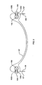
FIG. 1 is a side view of a support rack of the present invention;
FIG. 2 is a side view of a lower cradle in the support rack;
FIG. 3 is a cross-sectional view of the lower cradle of FIG. 2;
FIG. 4 is a side view of an upper cradle in the support rack;
FIG. 5 is a cross-sectional view of the upper cradle of FIG. 4;
FIG. 6 is a side view of the support rack of FIG. 1 adjusted to an arbitrary position; and
FIG. 7 is a top view of the support rack of FIG. 1, collapsed into a portable carrying case.
EMBODIMENT As shown in FIG. 1, a portable extremity support rack 100 exemplifying the invention is mounted on a rigid base 101 of a portable carrying case. A pair of lower rails 103 are pivotally connected to the base at a hinge 104 and pivotally connected to a pair of upper rails 105 at hinges 106. A lower cradle 107 is positioned on the lower rails and secured by knobs 108. An upper cradle 109 is positioned on the upper rails and secured in place by knobs 110. The upper and lower cradles both have U-shaped cross-sections.
An end-rest surface 122 extends from the upper cradle to support an extremity's outermost end, such as a foot. When the rack is used to support an injured arm, the surface 122 may comprise a peg (not shown) that can be grasped by a hand. The end-rest surface is pivotally hinged to a pair of rail extensions 124 at hinges 123 to allow, e.g., a foot or ankle to be positioned at a desired angle. The rail extensions telescope into the upper cradle as illustrated.
A pair of lower struts 111, that support the lower cradle, are pivotally mounted on the base 101 on one end and attached to the lower cradle at the other end. More specifically, the lower struts are pivotally attached to a bracket 119 that rests on a track 121 attached to the base. Each lower strut comprises a lower portion 112, connected to the bracket 119, and an extension portion 113 that telescopes into portion 112 and attaches to the lower cradle. The strut portions are held in position by a clamp (not shown) controlled by a knob 114. The bracket 119 is adjustably positioned along the track by setting a pin (not shown) into one of the holes 125 in the track.
As shown in FIGS. 2 and 3, the outer end of each extension portion 113 is pivotally connected by a hinge pin 126 to a flange 127 attached to the lower cradle. The knobs 108 on each side of the lower cradle are attached to bolts 108 a that are threaded through inserts 108 b in the lower cradle. Thus, rotation of the knobs applies clamping forces on the lower rails 103, thereby securing the position of the cradle on the rails.
Referring again to FIG. 1, a pair of upper struts 115, that support the upper cradle, are pivotally mounted on the base 101 on one end and attached to the upper cradle at the other end. More specifically, the upper struts are pivotally attached to a bracket 120 that rests on track 121 attached to the base. Each upper strut comprises a lower portion 116, connected to the bracket 120, and an extension portion 117 that telescopes into portion 116 and attaches to the upper cradle. The strut portions are held in position by a clamp (not shown) controlled by a knob 118. The bracket 120 is adjustably positioned along the track by setting a pin (not shown) into one of the holes 125 in the track.
As shown in FIGS. 4 and 5, the outer end of each extension portion 117 is pivotally connected by a hinge pin 128 to a flange 129 attached to the upper cradle. The knobs 110 on each side of the upper cradle are attached to bolts 110 a that are threaded through inserts 110 b in the upper cradle. Thus, rotation of the knobs applies clamping forces on the upper rails 105, thereby securing the position of the cradle on the rails.
FIGS. 1 and 6 illustrate the capability of the support rack to assume an almost unlimited variety of positions. As shown in FIG. 1, the lower cradle 107 is located a distance L1 from hinge 104, the upper cradle 109 is located a distance L2 from hinge 106 and the end-rest surface 122 is located a distance L3 from the upper cradle. Further, the lower struts are set at an angle a relative to the base and the upper struts are set at an angle β. In FIG. 6, the lower and upper struts are set at different angles, α′ and β′, relative to the base. Similarly, the upper and lower cradles and end-rest support are located in different positions than in FIG. 1, as shown by L1′, L2′ and L3′. Additionally, the positions of brackets 119 and 120 along the track 121 differ in FIGS. 1 and 6.
FIG. 7 illustrates the portable extremity support rack of FIG. 1 collapsed into a portable carrying case. The rack in its folded position is ideal for transport and/or storage.
Various modifications and additions can be made without departing from the spirit and scope of the invention. For example, at least one end of the base may be supported by one or more telescoping struts (not shown) that can adjustably incline the plane of the base. The base may additionally include panels (not shown) that telescope from its sides to increase the width of the base. Further, the base need not be mounted on the bottom of a carrying case, as shown in the illustrative embodiment. Instead, the base may be attached to the top or a side of the case, or, alternatively, may be portable independent of a carrying case.
It is expressly contemplated to pivotally hinge the upper and lower struts at fixed positions on the base and adjust their relative angles by adjustably attaching them to their respective cradles. Additionally, in lieu of the brackets described herein, the lower and upper struts may attach to the track using other known methods, such as clamping mechanisms. Further, those skilled in the art will understand that the clamps used as securing mechanisms in the present invention may be implemented with other equivalent mechanisms known in the art; e.g., setting a pin in one of a plurality of holes. Although U-shaped cross-sections are shown for the upper and lower cradles, their respective cross-sections may be tailored for extremities of different sizes and shapes. The cradles may be padded for extra comfort, e.g., with wool, foam, cloth, etc. Similarly, the end-rest surface may also be molded and/or padded. For example, the end-rest may be shaped as an oversized glove when the rack is used to support an injured arm. Also, one or more straps (not shown) may be attached to, e.g., the end-support, to provide added stability for an injured limb supported on the rack herein.
It will be understood by those skilled in the art that adjustment of the cradles, struts, brackets, rail extensions, etc. may be motorized to allow for passive range of motion. For example, the support rack may be adapted to provide continuous passive motion (CPM), e.g., by attaching motorized hydraulic pistons or jack screws to the struts. In addition, it is expressly contemplated that each strut supporting the upper and lower cradles may be independently adjustable. Therefore, by setting the struts supporting each side of a cradle to different lengths, the cradle may effectively be rotated clockwise or counter-clockwise to accommodate various shaped limbs. Accordingly this description is meant to be taken only by way of example and not to otherwise limit the scope of the invention.
Claims (10)
1. A portable extremity support rack comprising:
a generally planar base;
a pair of lower rails each pivotally connected at one end to the base;
a pair of upper rails each pivotally connected at one end to a corresponding lower rail;
a lower cradle adjustably positioned on the pair of lower rails;
an upper cradle adjustably positioned on the pair of upper rails;
a track attached to the base;
first and second brackets adjustably positioned at different locations on the track;
a pair of extendable lower struts, each of which is pivotally connected at a first end to the first bracket and attached at a second end to the lower cradle; and
a pair of extendable upper struts, each of which is pivotally connected at a first end to the second bracket and attached at a second end to the upper cradle,
whereby the angular orientations of the rails and the struts are adjustable by rotating them in a plane perpendicular to the base.
2. The support rack of claim 1 , wherein the upper cradle and the lower cradle have U-shaped cross-sections.
3. The support rack of claim 1 , further comprising:
a pair rail extensions oriented in the direction of the upper rails, each of which is attached to the upper cradle; and
an end-rest pivotally hinged to the pair of rail extensions,
whereby the angular orientation of the end-rest is adjustable by rotations in a plane perpendicular to the base.
4. The support rack of claim 3 , wherein the rail extensions are extendable from the upper cradle.
5. The support rack of claim 1 , wherein each strut comprises a first and second portion that telescope.
6. The support rack of claim 5 , wherein the lower cradle and the upper cradle have U-shaped cross-sections.
7. The support rack of claim 5 , further comprising:
a pair rail extensions oriented in the direction of the upper rails, each of which is attached to the upper cradle; and
an end-rest pivotally hinged to the pair of rail extensions,
whereby the angular orientation of the end-rest is adjustable by rotations in a plane perpendicular to the base.
8. The support rack of claim 7 , wherein the rail extensions are extendable from the upper cradle.
9. The support rack of claim 1 , wherein flanges are located on each side of the cradles and each flange is pivotally connected to a respective second end of a strut.
10. The support rack of claim 1 , wherein the rack is adapted to provide continuous passive range of motion.
Priority Applications (2)
| Application Number | Priority Date | Filing Date | Title |
|---|---|---|---|
| US10/254,149 US6764458B2 (en) | 2002-09-25 | 2002-09-25 | Extremity support rack |
| US10/832,956 US7156820B2 (en) | 2002-09-25 | 2004-04-27 | Extremity support rack |
Applications Claiming Priority (1)
| Application Number | Priority Date | Filing Date | Title |
|---|---|---|---|
| US10/254,149 US6764458B2 (en) | 2002-09-25 | 2002-09-25 | Extremity support rack |
Related Child Applications (1)
| Application Number | Title | Priority Date | Filing Date |
|---|---|---|---|
| US10/832,956 Continuation US7156820B2 (en) | 2002-09-25 | 2004-04-27 | Extremity support rack |
Publications (2)
| Publication Number | Publication Date |
|---|---|
| US20040059268A1 US20040059268A1 (en) | 2004-03-25 |
| US6764458B2 true US6764458B2 (en) | 2004-07-20 |
Family
ID=31993273
Family Applications (2)
| Application Number | Title | Priority Date | Filing Date |
|---|---|---|---|
| US10/254,149 Expired - Lifetime US6764458B2 (en) | 2002-09-25 | 2002-09-25 | Extremity support rack |
| US10/832,956 Expired - Fee Related US7156820B2 (en) | 2002-09-25 | 2004-04-27 | Extremity support rack |
Family Applications After (1)
| Application Number | Title | Priority Date | Filing Date |
|---|---|---|---|
| US10/832,956 Expired - Fee Related US7156820B2 (en) | 2002-09-25 | 2004-04-27 | Extremity support rack |
Country Status (1)
| Country | Link |
|---|---|
| US (2) | US6764458B2 (en) |
Cited By (10)
| Publication number | Priority date | Publication date | Assignee | Title |
|---|---|---|---|---|
| US20040204668A1 (en) * | 2002-09-25 | 2004-10-14 | Polonchek Jeanna S. | Extremity support rack |
| US20050003935A1 (en) * | 2003-07-03 | 2005-01-06 | Yamauchi Ken J. | Leg stretching apparatus |
| US6957463B2 (en) * | 2004-01-15 | 2005-10-25 | Falwell Robert L | Adjustable support device |
| US20060272893A1 (en) * | 2005-05-26 | 2006-12-07 | Joe Foggio | Therapeutic foot/leg/knee elevation |
| US20110000022A1 (en) * | 2008-02-29 | 2011-01-06 | The Ohio State University | Portable Extremity Assessment And Management Device |
| US20170143564A1 (en) * | 2015-11-23 | 2017-05-25 | Cardon Rehabilitation & Medical Equipment Ltd. | Multi-positional section for a treatment table |
| US20170312158A1 (en) * | 2011-02-16 | 2017-11-02 | Innovative Medical Products, Inc. | Lift for extremity surgical positioning device |
| USD805206S1 (en) * | 2014-12-15 | 2017-12-12 | Hailey Hill | Arm support |
| US9936812B2 (en) * | 2016-02-19 | 2018-04-10 | Frances Kessler | Leg support assembly |
| US20190350788A1 (en) * | 2018-05-16 | 2019-11-21 | Danny Moya | Adjustable leg lift |
Families Citing this family (14)
| Publication number | Priority date | Publication date | Assignee | Title |
|---|---|---|---|---|
| DE202006010947U1 (en) * | 2006-07-14 | 2006-09-07 | Forer, Karl | Device for immobilizing extremities of patients, comprises bearing surface, contact surfaces that hold the extremity in a anatomical position and are positioned along the bearing surface at drillings |
| GB2450894C (en) * | 2007-07-10 | 2017-03-22 | Genie Care | Apparatus for lifting and supporting the lower leg and foot of a patient |
| US20090112139A1 (en) * | 2007-10-29 | 2009-04-30 | Clote Chapman | Device to elevate to foot |
| US9265529B2 (en) * | 2010-11-30 | 2016-02-23 | Nikolaj Wolfson | Orthopedic fixation systems and methods |
| US20130012845A1 (en) * | 2011-07-07 | 2013-01-10 | Joseph Swoyer | Knee joint mobilizer |
| GB201116611D0 (en) | 2011-09-27 | 2011-11-09 | Provost Fellows Foundation Scholars And The Other Members Of Board Of College Of The Holy Undivided | A limb therapy device |
| WO2017053831A1 (en) * | 2015-09-25 | 2017-03-30 | Cain Frank J | Rehabilitation device for a damaged or surgically repaired knee |
| EP3399917B8 (en) * | 2016-01-08 | 2021-12-08 | Medtec Llc | Arm positioning device for supporting the arms of a patient in an arms-up position for therapeutic or diagnostic purposes |
| US20180055708A1 (en) * | 2016-08-29 | 2018-03-01 | Robert S. Hatch | Upper Extremity Positioner |
| US11576497B2 (en) * | 2019-10-11 | 2023-02-14 | Sean Kelly | Adjustable, lower back restoration device |
| CN110680649A (en) * | 2019-11-18 | 2020-01-14 | 苏燕敏 | Gynaecology and obstetrics is with limbs auxiliary stay device |
| US20220087886A1 (en) * | 2020-09-18 | 2022-03-24 | Modern Healthcare Equipment Llc | Portable medical lift and positioning device |
| CN113730134A (en) * | 2021-08-11 | 2021-12-03 | 川北医学院附属医院 | Adjustable bracket of mammary gland postoperative upper limbs nursing |
| CN113599133B (en) * | 2021-08-28 | 2022-11-11 | 蒋巍 | Operation auxiliary support with auxiliary rehabilitation structure for orthopedic treatment |
Citations (21)
| Publication number | Priority date | Publication date | Assignee | Title |
|---|---|---|---|---|
| US830776A (en) | 1906-05-18 | 1906-09-11 | Frederick W Flagg | Leg-rest. |
| US2519729A (en) | 1945-11-19 | 1950-08-22 | Alexander Thelma | Adjustable bed spring and mattress |
| US2552370A (en) | 1948-06-08 | 1951-05-08 | Curtis Cecil Claud | Adjustable folding leg support for inspection or surgical tables |
| US3066322A (en) | 1960-03-08 | 1962-12-04 | George T Derby | Leg and foot support |
| US3753557A (en) | 1971-09-03 | 1973-08-21 | E Kelley | Support for leg during knee surgery |
| US3817512A (en) | 1972-08-31 | 1974-06-18 | R Torrey | Genito-urinary examination device |
| US3931654A (en) | 1974-11-04 | 1976-01-13 | Spann Donald C | Leg positioner |
| US3946451A (en) | 1974-08-19 | 1976-03-30 | Spann Donald C | Limb support |
| US4146140A (en) | 1977-01-19 | 1979-03-27 | Adolf Suter | Support system |
| US4180254A (en) | 1977-04-01 | 1979-12-25 | National Research Development Corporation | Surgical apparatus |
| US4327714A (en) | 1977-03-24 | 1982-05-04 | Spann Donald C | Disposable orthopedic support |
| US4644593A (en) | 1985-10-09 | 1987-02-24 | Brien James A O | Variable support cushion for supporting anatomical body weight |
| US4665899A (en) * | 1984-09-27 | 1987-05-19 | Joint Mobilizer Systems Corp. | Apparatus for articulating the knee and hip joints |
| US4834073A (en) * | 1987-02-20 | 1989-05-30 | Medical Technology, Inc. | Passive motion exerciser |
| US4866796A (en) | 1985-04-17 | 1989-09-19 | Thomas J. Ring | Therapeutic table |
| US4910818A (en) | 1989-03-16 | 1990-03-27 | Robert Grabill | Leg positioning assembly |
| US4911152A (en) * | 1986-05-23 | 1990-03-27 | Aero Products, Inc. | Femoral traction splint |
| US5046487A (en) | 1989-12-12 | 1991-09-10 | Scott James W | Therapeutic leg elevator |
| US5342288A (en) * | 1992-08-03 | 1994-08-30 | Roger Lee | Traction splint |
| US5449221A (en) | 1994-03-07 | 1995-09-12 | Stander; Maxwell | Portable leg rest |
| US20030154550A1 (en) * | 2002-02-21 | 2003-08-21 | Murphy Stephen P. | Patient positioning device |
Family Cites Families (1)
| Publication number | Priority date | Publication date | Assignee | Title |
|---|---|---|---|---|
| US6764458B2 (en) * | 2002-09-25 | 2004-07-20 | Jeanna S. Polonchek | Extremity support rack |
-
2002
- 2002-09-25 US US10/254,149 patent/US6764458B2/en not_active Expired - Lifetime
-
2004
- 2004-04-27 US US10/832,956 patent/US7156820B2/en not_active Expired - Fee Related
Patent Citations (21)
| Publication number | Priority date | Publication date | Assignee | Title |
|---|---|---|---|---|
| US830776A (en) | 1906-05-18 | 1906-09-11 | Frederick W Flagg | Leg-rest. |
| US2519729A (en) | 1945-11-19 | 1950-08-22 | Alexander Thelma | Adjustable bed spring and mattress |
| US2552370A (en) | 1948-06-08 | 1951-05-08 | Curtis Cecil Claud | Adjustable folding leg support for inspection or surgical tables |
| US3066322A (en) | 1960-03-08 | 1962-12-04 | George T Derby | Leg and foot support |
| US3753557A (en) | 1971-09-03 | 1973-08-21 | E Kelley | Support for leg during knee surgery |
| US3817512A (en) | 1972-08-31 | 1974-06-18 | R Torrey | Genito-urinary examination device |
| US3946451A (en) | 1974-08-19 | 1976-03-30 | Spann Donald C | Limb support |
| US3931654A (en) | 1974-11-04 | 1976-01-13 | Spann Donald C | Leg positioner |
| US4146140A (en) | 1977-01-19 | 1979-03-27 | Adolf Suter | Support system |
| US4327714A (en) | 1977-03-24 | 1982-05-04 | Spann Donald C | Disposable orthopedic support |
| US4180254A (en) | 1977-04-01 | 1979-12-25 | National Research Development Corporation | Surgical apparatus |
| US4665899A (en) * | 1984-09-27 | 1987-05-19 | Joint Mobilizer Systems Corp. | Apparatus for articulating the knee and hip joints |
| US4866796A (en) | 1985-04-17 | 1989-09-19 | Thomas J. Ring | Therapeutic table |
| US4644593A (en) | 1985-10-09 | 1987-02-24 | Brien James A O | Variable support cushion for supporting anatomical body weight |
| US4911152A (en) * | 1986-05-23 | 1990-03-27 | Aero Products, Inc. | Femoral traction splint |
| US4834073A (en) * | 1987-02-20 | 1989-05-30 | Medical Technology, Inc. | Passive motion exerciser |
| US4910818A (en) | 1989-03-16 | 1990-03-27 | Robert Grabill | Leg positioning assembly |
| US5046487A (en) | 1989-12-12 | 1991-09-10 | Scott James W | Therapeutic leg elevator |
| US5342288A (en) * | 1992-08-03 | 1994-08-30 | Roger Lee | Traction splint |
| US5449221A (en) | 1994-03-07 | 1995-09-12 | Stander; Maxwell | Portable leg rest |
| US20030154550A1 (en) * | 2002-02-21 | 2003-08-21 | Murphy Stephen P. | Patient positioning device |
Non-Patent Citations (10)
| Title |
|---|
| AUTOFLEX II, Continuous Passive Motion, "The Comprehensive Answer to Post-Operative Therapy in the Hospital and at Home" Form 190 1103, Chattanooga Group, Inc. |
| Clinical Bibliography-CPM, "Shoulder", http://www.arthroscopy.com/sp06002.htm, Aug. 11, 2002. |
| Clinical Bibliography—CPM, "Shoulder", http://www.arthroscopy.com/sp06002.htm, Aug. 11, 2002. |
| EmployerHealth.com, "Employer Health Register, Directory of Products and Services, 'Continuous Passive Motion Devices (CPM)'", http://www.employerhealth.com/_sample_pages/dpscpm.htm, Aug. 11, 2002. |
| EmployerHealth.com, "Employer Health Register, Supplier Profile", http://www.employerhealth.com/_sample_pages/sp2979.htm, Aug. 11, 2002. |
| EmployerHealth.com, "Employer Health Register, Directory of Products and Services, ‘Continuous Passive Motion Devices (CPM)’", http://www.employerhealth.com/_sample_pages/dpscpm.htm, Aug. 11, 2002. |
| Pro-Med Products Catalog, pp. 30, 31, 46 and 47. |
| Span+Aid Cast Elevator advertisement, Span-America, Inc. South Carolina, 1978. |
| Sutter CarePlan II, Expanded Services for the Outpatient advertisement, "Sutter CPM 9000 Home Rehab System", Dec. 1992. |
| VQ OrthCARE, "Shoulder CPM", http://www.vqorthocare.com/cpm/shoulder.htm, Aug. 20, 2002. |
Cited By (14)
| Publication number | Priority date | Publication date | Assignee | Title |
|---|---|---|---|---|
| US20040204668A1 (en) * | 2002-09-25 | 2004-10-14 | Polonchek Jeanna S. | Extremity support rack |
| US7156820B2 (en) * | 2002-09-25 | 2007-01-02 | Polonchek Jeanna S | Extremity support rack |
| US20050003935A1 (en) * | 2003-07-03 | 2005-01-06 | Yamauchi Ken J. | Leg stretching apparatus |
| US7014602B2 (en) * | 2003-07-03 | 2006-03-21 | Yamauchi Ken J | Leg stretching apparatus |
| US6957463B2 (en) * | 2004-01-15 | 2005-10-25 | Falwell Robert L | Adjustable support device |
| US20060272893A1 (en) * | 2005-05-26 | 2006-12-07 | Joe Foggio | Therapeutic foot/leg/knee elevation |
| US20110000022A1 (en) * | 2008-02-29 | 2011-01-06 | The Ohio State University | Portable Extremity Assessment And Management Device |
| US8572781B2 (en) * | 2008-02-29 | 2013-11-05 | The Ohio State University | Portable extremity assessment and management device |
| US20170312158A1 (en) * | 2011-02-16 | 2017-11-02 | Innovative Medical Products, Inc. | Lift for extremity surgical positioning device |
| US10893995B2 (en) * | 2011-02-16 | 2021-01-19 | Innovative Medical Products, Inc. | Lift for extremity surgical positioning device |
| USD805206S1 (en) * | 2014-12-15 | 2017-12-12 | Hailey Hill | Arm support |
| US20170143564A1 (en) * | 2015-11-23 | 2017-05-25 | Cardon Rehabilitation & Medical Equipment Ltd. | Multi-positional section for a treatment table |
| US9936812B2 (en) * | 2016-02-19 | 2018-04-10 | Frances Kessler | Leg support assembly |
| US20190350788A1 (en) * | 2018-05-16 | 2019-11-21 | Danny Moya | Adjustable leg lift |
Also Published As
| Publication number | Publication date |
|---|---|
| US7156820B2 (en) | 2007-01-02 |
| US20040204668A1 (en) | 2004-10-14 |
| US20040059268A1 (en) | 2004-03-25 |
Similar Documents
| Publication | Publication Date | Title |
|---|---|---|
| US6764458B2 (en) | Extremity support rack | |
| US8001633B2 (en) | Spica table | |
| US10492973B2 (en) | Dual modality prone spine patient support apparatuses | |
| US5027799A (en) | Limb supporting device for arthroscopic surgery | |
| US6438777B1 (en) | Surgical supporting device | |
| US6874184B2 (en) | Leg support apparatus | |
| US6935992B2 (en) | Leg elevator system | |
| JPS62170249A (en) | Reversible walking device | |
| US20130111667A1 (en) | Multi-Functional, Convertible Treatment-Table | |
| US5524657A (en) | Universal attachment for walking assistive devices | |
| US5460596A (en) | Method and apparatus for stretching tight muscles | |
| US8852134B2 (en) | Portable splint system | |
| US20100269872A1 (en) | Enhanced crutch walker | |
| US20020095182A1 (en) | Physiotherapy bench | |
| US20070007400A1 (en) | Upper-body support device and method | |
| US6689030B1 (en) | Physical therapy method for treatment of shoulder muscle ailments and staff used therefore | |
| US6533743B1 (en) | Angularly adjustable traction apparatus | |
| US20170095402A1 (en) | Moveable Feet-walking Massage Grabbing Bar Rack | |
| US5730152A (en) | Surgical limb support and positioning structure | |
| US6758827B2 (en) | Angularly adjustable traction apparatus | |
| WO2005023072A1 (en) | Upper-body support device and method | |
| US20070143925A1 (en) | Multiple position surgery table foot support | |
| SU1088723A1 (en) | Apparatus for orthopedic operations | |
| US20180085275A1 (en) | Method and Apparatus for Variable Knee Flexion Support | |
| CN216168641U (en) | Movable bedside lithotomy position operation foot rest |
Legal Events
| Date | Code | Title | Description |
|---|---|---|---|
| STCF | Information on status: patent grant |
Free format text: PATENTED CASE |
|
| FPAY | Fee payment |
Year of fee payment: 4 |
|
| REMI | Maintenance fee reminder mailed | ||
| FPAY | Fee payment |
Year of fee payment: 8 |
|
| FPAY | Fee payment |
Year of fee payment: 12 |