US6774309B2 - Drainage construction of a waterproof cover of an electrical connection box - Google Patents

Drainage construction of a waterproof cover of an electrical connection box Download PDF

Info

Publication number
US6774309B2
US6774309B2 US10/459,302 US45930203A US6774309B2 US 6774309 B2 US6774309 B2 US 6774309B2 US 45930203 A US45930203 A US 45930203A US 6774309 B2 US6774309 B2 US 6774309B2
Authority
US
United States
Prior art keywords
waterproof cover
water
recess
electrical connection
casing
Prior art date
Legal status (The legal status is an assumption and is not a legal conclusion. Google has not performed a legal analysis and makes no representation as to the accuracy of the status listed.)
Expired - Fee Related
Application number
US10/459,302
Other versions
US20030230425A1 (en
Inventor
Koji Kasai
Current Assignee (The listed assignees may be inaccurate. Google has not performed a legal analysis and makes no representation or warranty as to the accuracy of the list.)
Sumitomo Wiring Systems Ltd
Original Assignee
Sumitomo Wiring Systems Ltd
Priority date (The priority date is an assumption and is not a legal conclusion. Google has not performed a legal analysis and makes no representation as to the accuracy of the date listed.)
Filing date
Publication date
Priority claimed from JP2002174235A external-priority patent/JP4096638B2/en
Priority claimed from US10/205,149 external-priority patent/US6635823B2/en
Application filed by Sumitomo Wiring Systems Ltd filed Critical Sumitomo Wiring Systems Ltd
Priority to US10/459,302 priority Critical patent/US6774309B2/en
Assigned to SUMITOMO WIRING SYSTEMS, LTD. reassignment SUMITOMO WIRING SYSTEMS, LTD. ASSIGNMENT OF ASSIGNORS INTEREST (SEE DOCUMENT FOR DETAILS). Assignors: KASAI, KOJI
Publication of US20030230425A1 publication Critical patent/US20030230425A1/en
Application granted granted Critical
Publication of US6774309B2 publication Critical patent/US6774309B2/en
Anticipated expiration legal-status Critical
Expired - Fee Related legal-status Critical Current

Links

Images

Classifications

    • HELECTRICITY
    • H02GENERATION; CONVERSION OR DISTRIBUTION OF ELECTRIC POWER
    • H02GINSTALLATION OF ELECTRIC CABLES OR LINES, OR OF COMBINED OPTICAL AND ELECTRIC CABLES OR LINES
    • H02G3/00Installations of electric cables or lines or protective tubing therefor in or on buildings, equivalent structures or vehicles
    • H02G3/02Details
    • H02G3/08Distribution boxes; Connection or junction boxes
    • H02G3/14Fastening of cover or lid to box

Definitions

  • the invention relates to a drainage construction of a waterproof cover of an electrical connection box and is particularly designed to prevent water from entering a junction box for an automobile vehicle.
  • junction boxes for automotive vehicles often are mounted below ducts of air conditioners in the vehicle. Waterdrops are likely to accumulate on the ducts and could drop down from the ducts and onto the junction boxes or wires that communicate with the junction boxes. These waterdrops could enter water-free areas of the junction boxes, such as the connector accommodating portions. Accordingly, junction boxes and related parts should be designed to prevent the entry of water.
  • FIG. 9 shows a junction box 1 with a casing and a connector accommodating portion 1 a in an upper surface of the casing.
  • a connector 2 is provided at an end of a wiring harness W/H and is fit into the connector accommodating portion 1 a .
  • a waterproof sheet 3 is adhered in a position to prevent waterdrops from entering the connector accommodating portion 1 a.
  • the above-described waterproof sheet 3 may deform during use into a shape that causes the waterdrops to flow in unexpected directions.
  • waterdrops that fall from the duct and onto the waterproof sheet 3 may run along the rear surface of the waterproof sheet 3 or otherwise flow from the sheet 3 into the water-free areas.
  • water that falls on the waterproof sheet 3 may stay on the sheet 3 without immediately running off the sheet 3 .
  • the accumulated water may run down at once due to an unexpected deformation of the waterproof sheet 3 and may be scattered in the water-free areas.
  • the present invention was developed in view of the above problems and an object thereof is to drain water reliably for preventing water from entering water-free areas of an electrical connection box, and to ensure that forgetfulness of an operator cannot lead to intrusion of water.
  • the invention is directed to a drainage construction of a waterproof or waterdeflecting cover of an electrical connection box.
  • the construction comprises a waterproof or waterdeflecting cover to be provided on an upper surface of a casing of an electrical connection box.
  • the waterproof cover comprises at least one recess for at least temporarily collecting or deviating water that falls down on the outer surface of the waterproof cover.
  • At least one water-diverting portion is formed by raising a portion of the recess, and by providing a dropping portion. Waterdrops that fall down on the outer surface of the waterproof cover stay at least temporarily in the recess and then drain along the dropping portion. Accordingly, a drainage path is set intentionally for the waterdrops. Therefore, waterdrops that fall down from the outer surface of the waterproof cover are prevented from dropping down onto the water-free areas of the electrical connection box.
  • At least one water collection causing portion may project up at another location.
  • the water collection causing portion may comprise at least one rib that projects up the other end of the recess.
  • the dropping portion preferably is below the water collection causing portion.
  • Waterdrops that fall down on the outer surface of the waterproof cover preferably are caused to stay at least temporarily in the recess and are caused to be drained along the dropping portion when the water level exceeds the height of the rib or other water collection causing portion.
  • waterdrops are collected first in the recess on the outer surface of the waterproof cover.
  • the water-diverting portion preferably is raised at one side of the recess with respect to the longitudinal direction. Thus, water in the recess is introduced to the side that has the dropping portion.
  • the rib or other water collection causing portion projects up at the other side to dam the water in the recess and to cause the water to stay at least temporarily in the recess.
  • the water can be caused to vaporize preferably without being drained out of the cover in the case of a small quantity of waterdrops.
  • Water in the recess may reach a level that exceeds the height of the rib or other water collection causing portion.
  • such water can be drained reliably to a place other than the water-free areas of the electrical connection box by running down on the dropping portion that projects below the rib or other water collection causing portion.
  • a groove preferably is formed vertically in the dropping portion of the waterproof cover for guiding the water.
  • water that drops down along the dropping portion can be guided reliably to an intended place along the groove.
  • the waterproof cover preferably is mounted rotatably or pivotably on a bracket for fixing the electrical connection box to a vehicle body to cover the upper surface of the casing.
  • a first connector preferably is fit into a connector accommodating portion in the upper surface of the casing with the waterproof cover rotated to a standby position that preferably is toward a side surface of the casing.
  • the cover substantially blocks entry of a connector into a connector accommodating portion in the side surface of the casing.
  • a second connector may be fit into the connector accommodating portion in the side surface of the casing when the waterproof cover is rotated to a proper position that preferably is toward the upper surface of the casing.
  • the connector accommodating portion in the side surface of the casing is covered at least partly by the waterproof cover when the first connector is fit into the connector accommodating portion in the upper surface of the casing.
  • the second connector cannot be fit into the connector accommodating portion unless and until the waterproof cover is rotated to the proper position.
  • a slanted guide portion preferably projects below the dropping portion, and a bottom end of the slanted guide portion is more outward than water-free areas of the electrical connection box.
  • Design factors may prevent the dropping portion of the waterproof cover from being more outward than the water-free areas of the electrical connection box.
  • the slanted guide portion in the standby state is below the dropping portion and drains water that drops down from the dropping portion outside the water-free areas of the electrical connection box.
  • the slanted guide portion may be formed integrally at the waterproof cover if permitted by design parameters.
  • FIG. 1 is a front view of a junction box according to one embodiment of the invention with a bracket and a waterproof cover mounted thereon.
  • FIG. 2 is a right side view in section of the junction box of FIG. 1 .
  • FIG. 3 is a left side view of the junction box of FIG. 1 .
  • FIG. 4 is a rear view of the junction box of FIG. 1 .
  • FIG. 5 (A) is a side view of the waterproof cover
  • FIG. 5 (B) is a top view of the waterproof cover.
  • FIG. 6 is a rear view of the bracket.
  • FIG. 7 is a section of an essential portion.
  • FIG. 8 is a perspective view of the essential portion.
  • FIG. 9 is a view of a prior art junction box.
  • a junction box according to the invention is identified by the numeral 10 in FIGS. 1 to 4 , on or to which a waterproof cover 13 is mounted is illustrated in FIGS. 1 to 4 .
  • the junction box 10 has a casing 11 with a side surface 11 a and an upper surface 11 b .
  • Connector accommodating portions 11 a - 1 and 11 b - 1 are provided respectively in the side and top surfaces 11 a and 11 b .
  • Busbars 15 and an EUC circuit board 16 are accommodated in the casing 11 to form a circuitry or a part of a circuitry.
  • a bracket 12 is mounted on the side surface 11 b of the casing 11 , as shown in FIG. 6 .
  • Mount portions 12 a , 12 b project up from substantially opposite sides of the bracket 12 for mounting the junction box 10 on a body of an automotive vehicle.
  • a slanted guide portion 12 c projects at the rear side of one mount portion 12 a and has a slanted portion 12 c - 1 and a substantially vertical portion 12 c - 2 .
  • a waterproof cover 13 is rotatably mounted on the bracket 12 , as shown in FIG. 5 . More particularly, the waterproof cover 13 has a substantially plate-shaped main body 13 h and walls 13 g project down toward the casing 11 from substantially opposite sides of the main body 13 h . Shafts 13 f project at the bottom ends of the walls 13 g and support the cover 13 rotatably on the bracket 12 .
  • the main body 13 h of the waterproof cover 13 has a recess 13 b for collecting water.
  • a first end of the recess 13 b with respect to the longitudinal direction is raised to form a water-diverting portion 13 d .
  • a rib 13 c projects up at the second end of the recess 13 b and has a shorter height than the water-diverting portion 13 d .
  • a dropping portion 13 e is formed substantially continuously with the one wall 13 g and projects downward below the rib 13 c.
  • a closing portion 13 a is provided at one side of the main body 13 h for substantially covering a part of the connector accommodating portion 11 a - 1 in the side surface 11 a of the casing 11 .
  • a groove 13 e - 1 is formed vertically in substantially the middle of the dropping portion 13 e.
  • the waterproof cover 13 is inclined toward the side surface 11 a of the casing 11 at an initial stage, as shown in FIGS. 1 to 4 , and a first connector (unillustrated) is fit into the connector accommodating portion 11 b - 1 in the upper surface 11 b of the casing 11 in this state.
  • the uppermost connector accommodating portion 11 a - 1 in the side surface 11 a of the casing 11 is covered partly by the closing portion 13 a of the waterproof cover 13 , and hence the connector cannot be fit into the connector accommodating portion 11 a - 1 .
  • the waterproof cover 13 then is rotated into a position to cover the upper surface 11 b of the casing 11 shown by phantom in FIGS. 2 and 3 and a second connector (unillustrated) is fit into the connector accommodating portion 11 a - 1 in the side surface 11 a of the casing 11 .
  • a proper position shown by phantom in FIGS. 2 and 3
  • the connector fitting operation is impossible unless the waterproof cover 13 is rotated into the proper position to substantially cover the upper surface 11 b.
  • the waterproof cover 13 is at the proper position shown in FIGS. 7 and 8 to cover the upper surface 11 b of the casing 11 . In this position, the dropping portion 13 e of the cover 13 overlaps the outer surface of the vertical portion 12 c - 2 of the slanted guide portion 12 c provided in a standby state at the bracket 12 .
  • Waterdrops M that fall down on the outer surface of the waterproof cover 13 are collected in the recess 13 b .
  • the water-diverting portion 13 d is raised at the one side of the recess 13 b and causes the waterdrops M to run toward the rib 13 c at the other side of the recess 13 b or down sloped towards the groove 12 e - 1 .
  • the waterdrops M collected in the recess 13 b are caused to stay in the recess 13 b and vaporize until reaching such a water level exceeding the rib 13 c.
  • the groove 13 e - 1 is formed in the dropping portion 13 e .
  • the water M is guided by the groove 13 e - 1 and runs reliably down onto the slanted guide 12 c.
  • the recess 13 b is slanted so that the waterdrops M run toward the side where the dropping portion 13 e is provided.
  • a drainage path for the waterdrops M that fall down on the outer surface of the waterproof cover 13 is intentionally set.
  • the waterdrops M dropping down from the waterproof cover 13 are prevented from entering the water-free areas (for example, connector accommodating portion) of the junction box 10 .
  • the waterproof cover 13 is rotatable in a space between the mount portions 12 a , 12 b of the bracket 12 .
  • a slanted guide projecting more outward than the dropping portion 13 e of the waterproof cover 13 since such a slanted guide interferes with the mount portion 12 a during rotation of the waterproof cover 13 .
  • the slanted guide 12 c is provided on the bracket 12 to receive the water dropping down from the dropping portion 13 e of the waterproof cover 13 , thereby enabling the water to be drained more outward than the water-free areas (for example, connector accommodating portion 13 b - 1 ) of the junction box 10 .
  • the slanted guide 12 c can be substantially continuous with the dropping portion 13 e of the waterproof cover 13 without any inconvenience in design, and may be formed integrally or unitarily at the waterproof cover 13 .
  • the invention has been described with respect to one recess 13 b having one water-diverting portion 13 d , one rib 13 c and one dropping portion 13 e .
  • the invention also is applicable to covers having two or more such elements appropriately arranged on its upper surface.
  • the rib 13 c can be replaced by a raised portion raised with respect to the bottom of the recess 13 b and forming another preferred water collection causing portion to allow at least temporarily collection of the water in the recess 13 b until the height of the water exceeds the projecting height of the raised portion.
  • the drainage path for the waterdrops that fall on the surface of the waterproof cover is set intentionally. Therefore, the waterdrops are prevented from dropping down from the waterproof cover onto the water-free areas of the electrical connection box.
  • the groove for guiding the water toward the dropping portion of the waterproof cover is vertical.
  • the waterdrops can securely drop down to an intended place along the groove.
  • the waterproof cover is rotatably or pivotably mounted and the connector cannot be fit into the connector accommodating portion in the side surface of the casing with the waterproof cover rotated toward the side surface of the casing.
  • the waterproof cover has to be rotated toward the upper surface of the casing to fit the second connector, thereby preventing the rotatable waterproof cover from being left unreturned.
  • the dropping portion of the waterproof cover might not be able to be at a position more outward than the water-free areas of the electrical connection box for a certain reason in designing, such as space efficiency.
  • the water dropping down from the dropping portion of the waterproof cover can be drained outside the water-free areas of the electrical connection box by the slanted guide by providing the slanted guide at the bracket below the dropping portion.

Abstract

A waterproof cover (13) is provided on an upper surface (11 b) of a casing(11) of an electrical connection box (10). The waterproof cover (13) is formed with a recess (13 b) for collecting water fallen down on the outer surface of the waterproof cover (13). One end of the recess (13 b) with respect to a longitudinal direction is raised to form a water-diverting portion (13 d), a rib (13 c) projects up at the other end of the recess (13 b), and a dropping portion (13 e) is provided below the rib (13 c). Waterdrops M that fall down on the outer surface of the waterproof cover (13) stay temporally in the recess (13 b) and drain along the dropping portion (13 e) when the water level thereof exceeds the rib (13 c). Further, a slanted guide (12 c) projects from a bracket (12) below the dropping portion (13 e).

Description

This application is a continuation-in-part of U.S. patent application Ser. No. 10/205,149 filed on Jul. 24, 2002 now U.S. Pat. No. 6,635,823.
BACKGROUND OF THE INVENTION
1. Field of the Invention
The invention relates to a drainage construction of a waterproof cover of an electrical connection box and is particularly designed to prevent water from entering a junction box for an automobile vehicle.
2. Description of the Related Art
Some junction boxes for automotive vehicles often are mounted below ducts of air conditioners in the vehicle. Waterdrops are likely to accumulate on the ducts and could drop down from the ducts and onto the junction boxes or wires that communicate with the junction boxes. These waterdrops could enter water-free areas of the junction boxes, such as the connector accommodating portions. Accordingly, junction boxes and related parts should be designed to prevent the entry of water.
FIG. 9 shows a junction box 1 with a casing and a connector accommodating portion 1 a in an upper surface of the casing. A connector 2 is provided at an end of a wiring harness W/H and is fit into the connector accommodating portion 1 a. A waterproof sheet 3 is adhered in a position to prevent waterdrops from entering the connector accommodating portion 1 a.
The above-described waterproof sheet 3 may deform during use into a shape that causes the waterdrops to flow in unexpected directions. Thus, waterdrops that fall from the duct and onto the waterproof sheet 3 may run along the rear surface of the waterproof sheet 3 or otherwise flow from the sheet 3 into the water-free areas. Further, water that falls on the waterproof sheet 3 may stay on the sheet 3 without immediately running off the sheet 3. In such a case, the accumulated water may run down at once due to an unexpected deformation of the waterproof sheet 3 and may be scattered in the water-free areas.
An operator may forget to adhere the waterproof sheet 3 after the connector 2 is fit into the connector accommodating portion 1 a of the junction box 1. Thus, water may enter the connector accommodating portion 1 a or other water-free areas of the junction box 1.
The present invention was developed in view of the above problems and an object thereof is to drain water reliably for preventing water from entering water-free areas of an electrical connection box, and to ensure that forgetfulness of an operator cannot lead to intrusion of water.
SUMMARY OF THE INVENTION
The invention is directed to a drainage construction of a waterproof or waterdeflecting cover of an electrical connection box. The construction comprises a waterproof or waterdeflecting cover to be provided on an upper surface of a casing of an electrical connection box. The waterproof cover comprises at least one recess for at least temporarily collecting or deviating water that falls down on the outer surface of the waterproof cover. At least one water-diverting portion is formed by raising a portion of the recess, and by providing a dropping portion. Waterdrops that fall down on the outer surface of the waterproof cover stay at least temporarily in the recess and then drain along the dropping portion. Accordingly, a drainage path is set intentionally for the waterdrops. Therefore, waterdrops that fall down from the outer surface of the waterproof cover are prevented from dropping down onto the water-free areas of the electrical connection box.
At least one water collection causing portion may project up at another location. The water collection causing portion may comprise at least one rib that projects up the other end of the recess.
The dropping portion preferably is below the water collection causing portion.
Waterdrops that fall down on the outer surface of the waterproof cover preferably are caused to stay at least temporarily in the recess and are caused to be drained along the dropping portion when the water level exceeds the height of the rib or other water collection causing portion.
More specifically, waterdrops are collected first in the recess on the outer surface of the waterproof cover. The water-diverting portion preferably is raised at one side of the recess with respect to the longitudinal direction. Thus, water in the recess is introduced to the side that has the dropping portion.
The rib or other water collection causing portion projects up at the other side to dam the water in the recess and to cause the water to stay at least temporarily in the recess. Thus, the water can be caused to vaporize preferably without being drained out of the cover in the case of a small quantity of waterdrops.
Water in the recess may reach a level that exceeds the height of the rib or other water collection causing portion. However, such water can be drained reliably to a place other than the water-free areas of the electrical connection box by running down on the dropping portion that projects below the rib or other water collection causing portion.
A groove preferably is formed vertically in the dropping portion of the waterproof cover for guiding the water. Thus, water that drops down along the dropping portion can be guided reliably to an intended place along the groove.
The waterproof cover preferably is mounted rotatably or pivotably on a bracket for fixing the electrical connection box to a vehicle body to cover the upper surface of the casing. A first connector preferably is fit into a connector accommodating portion in the upper surface of the casing with the waterproof cover rotated to a standby position that preferably is toward a side surface of the casing. Thus, the cover substantially blocks entry of a connector into a connector accommodating portion in the side surface of the casing. A second connector may be fit into the connector accommodating portion in the side surface of the casing when the waterproof cover is rotated to a proper position that preferably is toward the upper surface of the casing. With this construction, the connector accommodating portion in the side surface of the casing is covered at least partly by the waterproof cover when the first connector is fit into the connector accommodating portion in the upper surface of the casing. Thus, the second connector cannot be fit into the connector accommodating portion unless and until the waterproof cover is rotated to the proper position.
A slanted guide portion preferably projects below the dropping portion, and a bottom end of the slanted guide portion is more outward than water-free areas of the electrical connection box.
Design factors may prevent the dropping portion of the waterproof cover from being more outward than the water-free areas of the electrical connection box. However, the slanted guide portion in the standby state is below the dropping portion and drains water that drops down from the dropping portion outside the water-free areas of the electrical connection box.
The slanted guide portion may be formed integrally at the waterproof cover if permitted by design parameters.
These and other objects, features and advantages of the present invention will become more apparent upon reading of the following detailed description of preferred embodiments and accompanying drawings. It should be understood that even though embodiments are separately described, single features thereof may be combined to additional embodiments.
BRIEF DESCRIPTION OF THE DRAWINGS
FIG. 1 is a front view of a junction box according to one embodiment of the invention with a bracket and a waterproof cover mounted thereon.
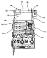
FIG. 2 is a right side view in section of the junction box of FIG. 1.
FIG. 3 is a left side view of the junction box of FIG. 1.
FIG. 4 is a rear view of the junction box of FIG. 1.
FIG. 5(A) is a side view of the waterproof cover, and FIG. 5(B) is a top view of the waterproof cover.
FIG. 6 is a rear view of the bracket.
FIG. 7 is a section of an essential portion.
FIG. 8 is a perspective view of the essential portion.
FIG. 9 is a view of a prior art junction box.
DETAILED DESCRIPTION OF THE PREFERRED EMBODIMENTS
A junction box according to the invention is identified by the numeral 10 in FIGS. 1 to 4, on or to which a waterproof cover 13 is mounted is illustrated in FIGS. 1 to 4.
As shown in FIG. 2, the junction box 10 has a casing 11 with a side surface 11 a and an upper surface 11 b. Connector accommodating portions 11 a-1 and 11 b-1 are provided respectively in the side and top surfaces 11 a and 11 b. Busbars 15 and an EUC circuit board 16 are accommodated in the casing 11 to form a circuitry or a part of a circuitry.
A bracket 12 is mounted on the side surface 11 b of the casing 11, as shown in FIG. 6. Mount portions 12 a, 12 b project up from substantially opposite sides of the bracket 12 for mounting the junction box 10 on a body of an automotive vehicle. A slanted guide portion 12 c projects at the rear side of one mount portion 12 a and has a slanted portion 12 c-1 and a substantially vertical portion 12 c-2.
A waterproof cover 13 is rotatably mounted on the bracket 12, as shown in FIG. 5. More particularly, the waterproof cover 13 has a substantially plate-shaped main body 13 h and walls 13 g project down toward the casing 11 from substantially opposite sides of the main body 13 h. Shafts 13 f project at the bottom ends of the walls 13 g and support the cover 13 rotatably on the bracket 12.
The main body 13 h of the waterproof cover 13 has a recess 13 b for collecting water. A first end of the recess 13 b with respect to the longitudinal direction is raised to form a water-diverting portion 13 d. A rib 13 c projects up at the second end of the recess 13 b and has a shorter height than the water-diverting portion 13 d. A dropping portion 13 e is formed substantially continuously with the one wall 13 g and projects downward below the rib 13 c.
A closing portion 13 a is provided at one side of the main body 13 h for substantially covering a part of the connector accommodating portion 11 a-1 in the side surface 11 a of the casing 11. A groove 13 e-1 is formed vertically in substantially the middle of the dropping portion 13 e.
The waterproof cover 13 is inclined toward the side surface 11 a of the casing 11 at an initial stage, as shown in FIGS. 1 to 4, and a first connector (unillustrated) is fit into the connector accommodating portion 11 b-1 in the upper surface 11 b of the casing 11 in this state.
The uppermost connector accommodating portion 11 a-1 in the side surface 11 a of the casing 11 is covered partly by the closing portion 13 a of the waterproof cover 13, and hence the connector cannot be fit into the connector accommodating portion 11 a-1. The waterproof cover 13 then is rotated into a position to cover the upper surface 11 b of the casing 11 shown by phantom in FIGS. 2 and 3 and a second connector (unillustrated) is fit into the connector accommodating portion 11 a-1 in the side surface 11 a of the casing 11. Thus, an operator cannot forget to return the waterproof cover 13 to a proper position (shown by phantom in FIGS. 2 and 3) because the connector fitting operation is impossible unless the waterproof cover 13 is rotated into the proper position to substantially cover the upper surface 11 b.
The waterproof cover 13 is at the proper position shown in FIGS. 7 and 8 to cover the upper surface 11 b of the casing 11. In this position, the dropping portion 13 e of the cover 13 overlaps the outer surface of the vertical portion 12 c-2 of the slanted guide portion 12 c provided in a standby state at the bracket 12.
Waterdrops M that fall down on the outer surface of the waterproof cover 13 are collected in the recess 13 b. The water-diverting portion 13 d is raised at the one side of the recess 13 b and causes the waterdrops M to run toward the rib 13 c at the other side of the recess 13 b or down sloped towards the groove 12 e-1.
The waterdrops M collected in the recess 13 b are caused to stay in the recess 13 b and vaporize until reaching such a water level exceeding the rib 13 c.
If the waterdrops M staying in the recess 13 b reach the water level exceeding the rib 13 c before vaporizing, the water M runs down through a cut 13 c-1 of the rib 13 c along the dropping portion 13 e toward the slanted guide 12 c.
The groove 13 e-1 is formed in the dropping portion 13 e. Thus, the water M is guided by the groove 13 e-1 and runs reliably down onto the slanted guide 12 c.
Water M that falls on the slanted guide 12 c is drained out of the junction box 10 along the slanted portion 12 c-1.
The recess 13 b is slanted so that the waterdrops M run toward the side where the dropping portion 13 e is provided.
A drainage path for the waterdrops M that fall down on the outer surface of the waterproof cover 13 is intentionally set. Thus, the waterdrops M dropping down from the waterproof cover 13 are prevented from entering the water-free areas (for example, connector accommodating portion) of the junction box 10.
The waterproof cover 13 is rotatable in a space between the mount portions 12 a, 12 b of the bracket 12. Thus, it is impossible to integrally or unitarily provide the waterproof cover 13 with a slanted guide projecting more outward than the dropping portion 13 e of the waterproof cover 13 since such a slanted guide interferes with the mount portion 12 a during rotation of the waterproof cover 13.
Therefore, the slanted guide 12 c is provided on the bracket 12 to receive the water dropping down from the dropping portion 13 e of the waterproof cover 13, thereby enabling the water to be drained more outward than the water-free areas (for example, connector accommodating portion 13 b-1) of the junction box 10.
The slanted guide 12 c can be substantially continuous with the dropping portion 13 e of the waterproof cover 13 without any inconvenience in design, and may be formed integrally or unitarily at the waterproof cover 13.
The invention has been described with respect to one recess 13 b having one water-diverting portion 13 d, one rib 13 c and one dropping portion 13 e. However, the invention also is applicable to covers having two or more such elements appropriately arranged on its upper surface.
Furthermore, the rib 13 c can be replaced by a raised portion raised with respect to the bottom of the recess 13 b and forming another preferred water collection causing portion to allow at least temporarily collection of the water in the recess 13 b until the height of the water exceeds the projecting height of the raised portion.
As is clear from the above description, the drainage path for the waterdrops that fall on the surface of the waterproof cover is set intentionally. Therefore, the waterdrops are prevented from dropping down from the waterproof cover onto the water-free areas of the electrical connection box.
The groove for guiding the water toward the dropping portion of the waterproof cover is vertical. Thus, the waterdrops can securely drop down to an intended place along the groove.
The waterproof cover is rotatably or pivotably mounted and the connector cannot be fit into the connector accommodating portion in the side surface of the casing with the waterproof cover rotated toward the side surface of the casing. Thus, the waterproof cover has to be rotated toward the upper surface of the casing to fit the second connector, thereby preventing the rotatable waterproof cover from being left unreturned.
The dropping portion of the waterproof cover might not be able to be at a position more outward than the water-free areas of the electrical connection box for a certain reason in designing, such as space efficiency. Thus, the water dropping down from the dropping portion of the waterproof cover can be drained outside the water-free areas of the electrical connection box by the slanted guide by providing the slanted guide at the bracket below the dropping portion.

Claims (10)

What is claimed is:
1. A drainage construction of a waterproof cover of an electrical connection box, comprising a waterproof cover to be provided on an upper surface of a casing of an electrical connection box,
wherein the waterproof cover comprises at least one recess for at least temporarily collecting water fallen down on the outer surface of the waterproof cover
at least one water-diverting portion formed by raising one end portion of the recess, and
a dropping portion at an end of the recess opposite the water-diverting portion and at least one rib projecting at a portion of the recess opposite the water-diverting portion, whereby waterdrops that fall down on the outer surface of the waterproof cover stay at least temporarily in the recess and subsequently drain along the dropping portion.
2. The drainage construction 1, wherein the dropping portion is below the rib.
3. The drainage construction of claim 2, wherein waterdrops that fall on the outer surface of the waterproof cover stay at least temporarily in the recess and drain along the dropping portion when a level of water exceeds the rib.
4. The drainage construction of claim 1, wherein a groove for guiding the water is formed in the dropping portion of the waterproof cover.
5. A drainage construction of a waterproof cover of an electrical connection box, comprising a waterproof cover to be provided on an upper surface of a casing of an electrical connection box,
wherein the waterproof cover comprises at least one recess for at least temporarily collecting water fallen down on the outer surface of the waterproof cover, the waterproof cover being rotatably mountable on a bracket for fixing the electrical connection box to a vehicle body to cover the upper surface of the casing;
at least one water-diverting portion formed by raising one end portion of the recess, and
a dropping portion at an end of the recess opposite the water-diverting portion, whereby waterdrops that fall down on the outer surface of the waterproof cover stay at least temporarily in the recess and subsequently drain along the dropping portion.
6. The drainage construction of claim 5, wherein at least one rib projects at portion of the recess opposite the water-diverting portion.
7. The drainage construction of claim 5, wherein a first connector is fittable into a connector accommodating portion in the upper surface of the casing with the waterproof cover rotated to a standby position toward a side surface of the casing to block the entrance of a second connector into a connector accommodating portion in the side surface of the casing and the second connector is fittable into the connector accommodating portion in the side surface of the casing with the waterproof cover rotated to a proper position toward the upper surface of the casing.
8. The drainage construction of claim 5, wherein a slanted guide portion projects from the bracket substantially below the dropping portion, and a bottom end of the slanted guide portion is located more outward than water-free areas of the electrical connection box.
9. The electrical connection box of claim 5, wherein a slanted guide portion projects from the bracket at a position below the dropping portion, the slanted guide portion having a bottom end located more outward than water-free areas of the electrical connection box.
10. A waterproof cover for an electrical connection box, the waterproof cover comprising a main body with opposite first and second ends, at least one recess for at least temporarily collecting water fallen down on the outer surface of the waterproof cover, a water-diverting portion at the first end of the main body and projecting up from the recess, a rib at the second end of the main body and projecting up from the recess by a height less than the water-diverting portion and a dropping portion at the second end of the main body and extending down below the recess, whereby waterdrops that fall down on the outer surface of the waterproof cover stay at least temporarily in the recess and subsequently drain along the dropping portion.
US10/459,302 2002-06-14 2003-06-11 Drainage construction of a waterproof cover of an electrical connection box Expired - Fee Related US6774309B2 (en)

Priority Applications (1)

Application Number Priority Date Filing Date Title
US10/459,302 US6774309B2 (en) 2002-06-14 2003-06-11 Drainage construction of a waterproof cover of an electrical connection box

Applications Claiming Priority (4)

Application Number Priority Date Filing Date Title
JP2002-174235 2002-06-14
JP2002174235A JP4096638B2 (en) 2002-06-14 2002-06-14 Drainage structure of waterproof cover of electrical junction box
US10/205,149 US6635823B2 (en) 2001-07-26 2002-07-24 Cover for preventing water from entering a junction block
US10/459,302 US6774309B2 (en) 2002-06-14 2003-06-11 Drainage construction of a waterproof cover of an electrical connection box

Related Parent Applications (1)

Application Number Title Priority Date Filing Date
US10/205,149 Continuation-In-Part US6635823B2 (en) 2001-07-26 2002-07-24 Cover for preventing water from entering a junction block

Publications (2)

Publication Number Publication Date
US20030230425A1 US20030230425A1 (en) 2003-12-18
US6774309B2 true US6774309B2 (en) 2004-08-10

Family

ID=29738408

Family Applications (1)

Application Number Title Priority Date Filing Date
US10/459,302 Expired - Fee Related US6774309B2 (en) 2002-06-14 2003-06-11 Drainage construction of a waterproof cover of an electrical connection box

Country Status (1)

Country Link
US (1) US6774309B2 (en)

Cited By (12)

* Cited by examiner, † Cited by third party
Publication number Priority date Publication date Assignee Title
US20060027384A1 (en) * 2004-08-05 2006-02-09 Scanzillo Thomas L Large capacity multiple service floor box
US20080053678A1 (en) * 2006-08-31 2008-03-06 Yazaki Corporation Electrical connection box
US20080055821A1 (en) * 2005-04-11 2008-03-06 Autonetworks Technologies, Ltd. Electric Power Distribution System
US20090130882A1 (en) * 2007-11-15 2009-05-21 Sumitomo Wiring Systems, Ltd. Electrical junction box
US20090273902A1 (en) * 2004-10-21 2009-11-05 Mitsubishi Denki Kabushiki Kaisha Outdoor apparatus
US20100326719A1 (en) * 2009-06-30 2010-12-30 Sumitomo Wiring Systems, Ltd. Electrical junction box
US20130078846A1 (en) * 2010-02-23 2013-03-28 Yazaki Corporation Inlet assembly
US20140151112A1 (en) * 2012-11-30 2014-06-05 Yazaki Corporation Case
US20150255969A1 (en) * 2012-10-04 2015-09-10 Sumitomo Wiring Systems, Ltd. Electrical junction box
US20170086318A1 (en) * 2015-09-17 2017-03-23 Fujitsu Ten Limited Electronic apparatus
US9972935B2 (en) * 2016-07-06 2018-05-15 Sumitomo Wiring Systems, Ltd. Drainage structure for electrical connection box
US10653030B1 (en) * 2018-11-30 2020-05-12 Illinois Tool Works Inc. Water ingress prevention in electronic components

Families Citing this family (1)

* Cited by examiner, † Cited by third party
Publication number Priority date Publication date Assignee Title
JP6431016B2 (en) * 2016-10-12 2018-11-28 矢崎総業株式会社 Electrical junction box and wire harness

Citations (14)

* Cited by examiner, † Cited by third party
Publication number Priority date Publication date Assignee Title
US5557067A (en) * 1993-07-22 1996-09-17 Communications Technology Corporation Pole mounted terminal housing
US5574254A (en) 1994-05-25 1996-11-12 Yazaki Corporation Water-proof sealing structure for an electric junction box
US5674090A (en) 1995-03-15 1997-10-07 Sumitomo Wiring Systems, Ltd. Casing for receiving electrical connection box
US5755579A (en) 1994-12-28 1998-05-26 Yazaki Corporation Simplified connecting-type electric junction box with wiring harness
US5864091A (en) * 1996-07-03 1999-01-26 Sumitomo Wiring Systems, Ltd. Shock resistant electrical connection box
US5995380A (en) 1998-05-12 1999-11-30 Lear Automotive Dearborn, Inc. Electric junction box for an automotive vehicle
US6008454A (en) * 1997-02-25 1999-12-28 Sumitomo Wiring Systems, Ltd. Storage box for electronic control units
US6045412A (en) 1997-11-25 2000-04-04 Yazaki Corporation Power distribution center with terminal holder
US6077102A (en) 1997-06-09 2000-06-20 General Motors Corporation Top down electrical distribution center assembly
US6108202A (en) 1996-07-03 2000-08-22 Sumitomo Wiring Systems, Ltd. Electric connection box
US6121548A (en) 1997-09-24 2000-09-19 Sumitomo Wiring Systems, Ltd. Electrical connection box
US6462270B1 (en) 2001-04-18 2002-10-08 Sumitomo Electric Wiring Systems, Inc. Two-piece junction box cover having gutters for reducing water infiltration
US6545217B2 (en) 2001-06-12 2003-04-08 Yazaki Corporation Electrical junction box having double-wall structure
US6635823B2 (en) * 2001-07-26 2003-10-21 Sumitomo Wiring Systems, Ltd. Cover for preventing water from entering a junction block

Patent Citations (14)

* Cited by examiner, † Cited by third party
Publication number Priority date Publication date Assignee Title
US5557067A (en) * 1993-07-22 1996-09-17 Communications Technology Corporation Pole mounted terminal housing
US5574254A (en) 1994-05-25 1996-11-12 Yazaki Corporation Water-proof sealing structure for an electric junction box
US5755579A (en) 1994-12-28 1998-05-26 Yazaki Corporation Simplified connecting-type electric junction box with wiring harness
US5674090A (en) 1995-03-15 1997-10-07 Sumitomo Wiring Systems, Ltd. Casing for receiving electrical connection box
US6108202A (en) 1996-07-03 2000-08-22 Sumitomo Wiring Systems, Ltd. Electric connection box
US5864091A (en) * 1996-07-03 1999-01-26 Sumitomo Wiring Systems, Ltd. Shock resistant electrical connection box
US6008454A (en) * 1997-02-25 1999-12-28 Sumitomo Wiring Systems, Ltd. Storage box for electronic control units
US6077102A (en) 1997-06-09 2000-06-20 General Motors Corporation Top down electrical distribution center assembly
US6121548A (en) 1997-09-24 2000-09-19 Sumitomo Wiring Systems, Ltd. Electrical connection box
US6045412A (en) 1997-11-25 2000-04-04 Yazaki Corporation Power distribution center with terminal holder
US5995380A (en) 1998-05-12 1999-11-30 Lear Automotive Dearborn, Inc. Electric junction box for an automotive vehicle
US6462270B1 (en) 2001-04-18 2002-10-08 Sumitomo Electric Wiring Systems, Inc. Two-piece junction box cover having gutters for reducing water infiltration
US6545217B2 (en) 2001-06-12 2003-04-08 Yazaki Corporation Electrical junction box having double-wall structure
US6635823B2 (en) * 2001-07-26 2003-10-21 Sumitomo Wiring Systems, Ltd. Cover for preventing water from entering a junction block

Cited By (25)

* Cited by examiner, † Cited by third party
Publication number Priority date Publication date Assignee Title
US7388164B2 (en) 2004-08-05 2008-06-17 Hubbell Incorporated Large capacity multiple service floor box
US20060027384A1 (en) * 2004-08-05 2006-02-09 Scanzillo Thomas L Large capacity multiple service floor box
US20090273902A1 (en) * 2004-10-21 2009-11-05 Mitsubishi Denki Kabushiki Kaisha Outdoor apparatus
US7800889B2 (en) * 2004-10-21 2010-09-21 Mitsubishi Denki Kabushiki Kaisha Outdoor apparatus
US7835141B2 (en) 2005-04-11 2010-11-16 Autonetworks Technologies, Ltd. Electric power distribution system
US20080055821A1 (en) * 2005-04-11 2008-03-06 Autonetworks Technologies, Ltd. Electric Power Distribution System
US7639476B2 (en) * 2005-04-11 2009-12-29 Sumitomo Wiring Systems, Ltd. Electric power distribution system
US20100039753A1 (en) * 2005-04-11 2010-02-18 Autonetworks Technologies, Ltd. Electric Power Distribution System
US20080053678A1 (en) * 2006-08-31 2008-03-06 Yazaki Corporation Electrical connection box
US7671275B2 (en) * 2006-08-31 2010-03-02 Yazaki Corporation Electrical connection box
US7931478B2 (en) * 2007-11-15 2011-04-26 Sumitomo Wiring Systems, Ltd. Electrical junction box
US20090130882A1 (en) * 2007-11-15 2009-05-21 Sumitomo Wiring Systems, Ltd. Electrical junction box
USRE45621E1 (en) * 2009-06-30 2015-07-21 Sumitomo Wiring Systems, Ltd. Electrical junction box
US8383963B2 (en) * 2009-06-30 2013-02-26 Sumitomo Wiring Systems, Ltd. Electrical junction box
US20100326719A1 (en) * 2009-06-30 2010-12-30 Sumitomo Wiring Systems, Ltd. Electrical junction box
US20130078846A1 (en) * 2010-02-23 2013-03-28 Yazaki Corporation Inlet assembly
US8827731B2 (en) * 2010-02-23 2014-09-09 Toyota Jidosha Kabushiki Kaisha Inlet assembly
US20150255969A1 (en) * 2012-10-04 2015-09-10 Sumitomo Wiring Systems, Ltd. Electrical junction box
US9293902B2 (en) * 2012-10-04 2016-03-22 Sumitomo Wiring Systems, Ltd. Electrical junction box
US20140151112A1 (en) * 2012-11-30 2014-06-05 Yazaki Corporation Case
US9142944B2 (en) * 2012-11-30 2015-09-22 Yazaki Corporation Case
US20170086318A1 (en) * 2015-09-17 2017-03-23 Fujitsu Ten Limited Electronic apparatus
US9832893B2 (en) * 2015-09-17 2017-11-28 Fujitsu Ten Limited Electronic apparatus with case having unitary fixture reinforcement and roof for connector aperture
US9972935B2 (en) * 2016-07-06 2018-05-15 Sumitomo Wiring Systems, Ltd. Drainage structure for electrical connection box
US10653030B1 (en) * 2018-11-30 2020-05-12 Illinois Tool Works Inc. Water ingress prevention in electronic components

Also Published As

Publication number Publication date
US20030230425A1 (en) 2003-12-18

Similar Documents

Publication Publication Date Title
US6774309B2 (en) Drainage construction of a waterproof cover of an electrical connection box
US6982379B2 (en) Automotive electrical connection box and a method of mounting it
JP4585980B2 (en) Electrical junction box
JP5173596B2 (en) Electrical junction box
US9374916B2 (en) Electrical junction box
US20100326690A1 (en) Electrical junction box
WO2010021270A1 (en) Protector and wire harness
US9204562B2 (en) Electrical junction box
JP2009131088A (en) Electrical connection box
US6971888B2 (en) Waterproof structure of electric junction box
US9391437B2 (en) Electrical junction box
JP2014103797A (en) Electric connection box
JP5057037B2 (en) Battery arrangement structure for automobiles
JP2009124874A (en) Electrical junction box
JP4096638B2 (en) Drainage structure of waterproof cover of electrical junction box
JP3334643B2 (en) Electrical junction box
JP2012085473A (en) Drain structure of on-vehicle protector
JP4002801B2 (en) Drainage structure of electrical junction box
US6635823B2 (en) Cover for preventing water from entering a junction block
JP3464394B2 (en) Drainage structure of electrical junction box
JP3473474B2 (en) Connector connection box
JP2001102768A (en) Electrical connection box
JP2000023332A (en) Drain structure of housing block
JP3452504B2 (en) Electrical junction box
JP2005151711A (en) Vehicular electric box

Legal Events

Date Code Title Description
AS Assignment

Owner name: SUMITOMO WIRING SYSTEMS, LTD., JAPAN

Free format text: ASSIGNMENT OF ASSIGNORS INTEREST;ASSIGNOR:KASAI, KOJI;REEL/FRAME:014173/0721

Effective date: 20030604

FEPP Fee payment procedure

Free format text: PAYOR NUMBER ASSIGNED (ORIGINAL EVENT CODE: ASPN); ENTITY STATUS OF PATENT OWNER: LARGE ENTITY

FPAY Fee payment

Year of fee payment: 4

FPAY Fee payment

Year of fee payment: 8

REMI Maintenance fee reminder mailed
LAPS Lapse for failure to pay maintenance fees
STCH Information on status: patent discontinuation

Free format text: PATENT EXPIRED DUE TO NONPAYMENT OF MAINTENANCE FEES UNDER 37 CFR 1.362

FP Lapsed due to failure to pay maintenance fee

Effective date: 20160810