US6778690B1 - Prostate boundary segmentation from 2D and 3D ultrasound images - Google Patents
Prostate boundary segmentation from 2D and 3D ultrasound images Download PDFInfo
- Publication number
- US6778690B1 US6778690B1 US09/373,954 US37395499A US6778690B1 US 6778690 B1 US6778690 B1 US 6778690B1 US 37395499 A US37395499 A US 37395499A US 6778690 B1 US6778690 B1 US 6778690B1
- Authority
- US
- United States
- Prior art keywords
- points
- ddc
- prostate
- boundary
- image
- Prior art date
- Legal status (The legal status is an assumption and is not a legal conclusion. Google has not performed a legal analysis and makes no representation as to the accuracy of the status listed.)
- Expired - Lifetime
Links
Images


Classifications
-
- A—HUMAN NECESSITIES
- A61—MEDICAL OR VETERINARY SCIENCE; HYGIENE
- A61B—DIAGNOSIS; SURGERY; IDENTIFICATION
- A61B8/00—Diagnosis using ultrasonic, sonic or infrasonic waves
-
- G—PHYSICS
- G06—COMPUTING; CALCULATING OR COUNTING
- G06T—IMAGE DATA PROCESSING OR GENERATION, IN GENERAL
- G06T7/00—Image analysis
- G06T7/0002—Inspection of images, e.g. flaw detection
- G06T7/0012—Biomedical image inspection
-
- G—PHYSICS
- G06—COMPUTING; CALCULATING OR COUNTING
- G06T—IMAGE DATA PROCESSING OR GENERATION, IN GENERAL
- G06T7/00—Image analysis
- G06T7/10—Segmentation; Edge detection
- G06T7/12—Edge-based segmentation
-
- G—PHYSICS
- G06—COMPUTING; CALCULATING OR COUNTING
- G06T—IMAGE DATA PROCESSING OR GENERATION, IN GENERAL
- G06T7/00—Image analysis
- G06T7/10—Segmentation; Edge detection
- G06T7/149—Segmentation; Edge detection involving deformable models, e.g. active contour models
-
- A—HUMAN NECESSITIES
- A61—MEDICAL OR VETERINARY SCIENCE; HYGIENE
- A61N—ELECTROTHERAPY; MAGNETOTHERAPY; RADIATION THERAPY; ULTRASOUND THERAPY
- A61N5/00—Radiation therapy
- A61N5/10—X-ray therapy; Gamma-ray therapy; Particle-irradiation therapy
- A61N5/103—Treatment planning systems
-
- G—PHYSICS
- G06—COMPUTING; CALCULATING OR COUNTING
- G06T—IMAGE DATA PROCESSING OR GENERATION, IN GENERAL
- G06T2207/00—Indexing scheme for image analysis or image enhancement
- G06T2207/10—Image acquisition modality
- G06T2207/10132—Ultrasound image
- G06T2207/10136—3D ultrasound image
-
- G—PHYSICS
- G06—COMPUTING; CALCULATING OR COUNTING
- G06T—IMAGE DATA PROCESSING OR GENERATION, IN GENERAL
- G06T2207/00—Indexing scheme for image analysis or image enhancement
- G06T2207/20—Special algorithmic details
- G06T2207/20092—Interactive image processing based on input by user
- G06T2207/20101—Interactive definition of point of interest, landmark or seed
-
- G—PHYSICS
- G06—COMPUTING; CALCULATING OR COUNTING
- G06T—IMAGE DATA PROCESSING OR GENERATION, IN GENERAL
- G06T2207/00—Indexing scheme for image analysis or image enhancement
- G06T2207/30—Subject of image; Context of image processing
- G06T2207/30004—Biomedical image processing
- G06T2207/30081—Prostate
-
- Y—GENERAL TAGGING OF NEW TECHNOLOGICAL DEVELOPMENTS; GENERAL TAGGING OF CROSS-SECTIONAL TECHNOLOGIES SPANNING OVER SEVERAL SECTIONS OF THE IPC; TECHNICAL SUBJECTS COVERED BY FORMER USPC CROSS-REFERENCE ART COLLECTIONS [XRACs] AND DIGESTS
- Y10—TECHNICAL SUBJECTS COVERED BY FORMER USPC
- Y10S—TECHNICAL SUBJECTS COVERED BY FORMER USPC CROSS-REFERENCE ART COLLECTIONS [XRACs] AND DIGESTS
- Y10S128/00—Surgery
- Y10S128/916—Ultrasound 3-D imaging
Definitions
- This invention relates in general to medical imaging systems, and more specifically to a method of prostate boundary segmentation from 2D and 3D ultrasound images.
- Prostate cancer is the most commonly diagnosed malignancy in men over the age of 50, and is found at autopsy in 30% of men at the age of 50, 40% at age 60, and almost 90% at age 90. Worldwide, it is the second leading cause of death due to cancer in men, accounting for between 2.1% and 15.2% of all cancer deaths. In Canada, about 20,000 new prostate cancer cases will be diagnosed and about 4,000 men will die from this disease every year.
- Symptoms due to carcinoma of the prostate are generally absent until extensive local growth or metastases develop, accounting for the fact that only 65% of patients are diagnosed with locally confined disease. Once the tumour has extended beyond the prostate, the risk of metastasis increases dramatically. Tumours smaller than 1 to 1.5 cm 3 rarely broach the prostatic capsule. When diagnosed at this early stage, the disease is curable, and even at later stages treatment can be effective. Nevertheless, treatment options vary depending on the extent of the cancer, and prognosis worsens when diagnosis occurs at an advanced stage.
- the challenges facing physicians managing patients with possible prostate cancer are to: (a) diagnose clinically relevant cancers at a stage when they are curable, (b) stage and grade the disease accurately, (c) apply the appropriate therapy accurately to optimize destruction of cancer cells while preserving adjacent normal tissues, (d) follow patients to assess side effects and the effectiveness of the therapy.
- An important aspect in the establishment of the appropriate prostate therapy is the accurate segmentation (i.e., extraction) of the prostate boundary and other anatomical structures (rectal wall, urethra, bladder). Assignment of the appropriate therapy or dose to the prostate requires that the prostate volume be accurately measured.
- the segmentation task is relatively easy and many approaches can be used.
- ultrasound images of the prostate are very difficult to segment because the contrast is low, and the image suffers from speckle, shadowing and other artifacts.
- traditional local image processing operators like edge detectors are inadequate in and of themselves for finding the boundary, due to speckle, shadowing and other image artifacts.
- Region-based neural net approaches require extensive teaching sets, are slow, and make addition of user specified boundary information difficult.
- Contour-based methods such as “snakes” implementation of active contours are slow, complex, and sensitive to the initial choice of contour.
- a fast semi-automatic prostate contouring method is provided using model-based initialization and an efficient Discrete Dynamic Contour (DDC) for boundary refinement.
- DDC Discrete Dynamic Contour
- the method of the present invention can encompass a 2D segmentation technique or alternatively extend to the segmentation of objects in 3D
- the method of the present invention has particular application during the pre-implant planning phase of a brachytherapy procedure. However, this method also has uses in any phase of dose planning in the brachytherapy procedure or any other therapy approach.
- FIGS. 1 ( a )- 1 ( d ) show a prior art segmentation technique using DDC, wherein FIG. 1 ( a ) shows an initial DDC drawn by the user, FIG. 1 ( b ) shows the early stage of deformation, FIG. 1 ( c ) shows the later stage of deformation, and FIG. 1 ( d ) shows the final deformed DDC.
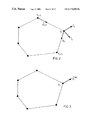
- FIG. 2 shows an example of configuration of the prior art DDC.
- FIG. 3 shows forces as vector quantities having both direction and magnitude, for the configuration of FIG. 2 .
- FIGS. 4 ( a )- 4 ( c ) show image energy and force field for a vertical edge of an ultrasound image, wherein FIG. 4 ( a ) shows the edge modeled as a step edge (i.e., an edge wherein there is a drastic transition in gray levels, FIG. 4 ( b ) shows the energy field associated with the edge, and FIG. 4 ( c ) shows the image force field.
- FIG. 4 ( a ) shows the edge modeled as a step edge (i.e., an edge wherein there is a drastic transition in gray levels
- FIG. 4 ( b ) shows the energy field associated with the edge
- FIG. 4 ( c ) shows the image force field.
- FIGS. 5 ( a ) and 5 ( b ) are a representation of a curvature vector as a measure of angle between edges for 5 ( a ) a large curvature, and 5 ( b ) a small curvature.
- FIG. 6 Flow chart showing implementation of the DDC deformation process utilized in the method of the present invention.
- FIG. 7 is a flowchart for the 2D segmentation algorithm according to the present invention.
- FIG. 8 shows the location of four user-selected points, labeled (1) to (4), on a prostate boundary, according to the method of the present invention.
- FIGS. 9 ( a ) and 9 ( b ) show a first example of operation of the prostate segmentation algorithm of the present invention wherein FIG. 9 ( a ) shows an initial outline with four user-selected points, and FIG. 9 ( b ) shows the final segmented outline obtained after deforming the DDC.
- FIG. 12 shows a schematic diagram showing how the method to select sequences of 2D images out of the 3D volume to be used for the segmentation.
- FIGS. 13 ( a )- 13 ( ii ) show a sequence of 2D images of the prostate segmented using the semi-automatic segmentation procedure extended to 3D.
- the images are parallel to each other separated by 1 mm.
- Image no. 15 was used to initiate the process by the semi-automatic 2D segmentation technique.
- the final boundary was used to initiate the segmentation of the next image. This process was repeated until the complete prostate was segmented.
- DDC is a poly-line (i.e., a sequence of points connected by straight-line segments) used to deform a contour to fit features in an image.
- DDC is a poly-line (i.e., a sequence of points connected by straight-line segments) used to deform a contour to fit features in an image.
- the user When using the DDC to segment an object from an image as originally described by Lobregt and Viergever in “A discrete dynamic contour model”, IEEE Trans. Med. imag. 1995; 14:12-24, the user must first draw an approximate outline of the object.
- An example outline is shown in FIG. 1 ( a ) for a typical 2D US (ultrasound) image of the prostate
- the DOC is initialized to this outline and is automatically deformed to fit features of interest, which in this case consist of edges that define the boundary of the prostate.
- FIG. 1 ( b ) and 1 ( c ) show two stages in the deformation of the DDC. Note that points are automatically added to or deleted from the DDC as it deforms to allow it to better conform to the boundary.
- FIG. 1 ( d ) shows the final deformed DDC. In this example, the final shape conforms well to the prostate boundary except in some areas where artifacts and noise in the image cause parts of the DDC to deform towards them and away from the prostate boundary.
- the configuration of the DDC is shown in FIG. 2 .
- the unit edge vector ⁇ circumflex over (d) ⁇ i points from vertex i to vertex i+1.
- a local radial unit vector ⁇ circumflex over (r) ⁇ 1 can be computed from ⁇ circumflex over (t) ⁇ i by rotating it by B/2 radians: ⁇ circumflex over (r) ⁇ i and ⁇ circumflex over (t) ⁇ i define a local coordinate system attached to vertex t.
- r ⁇ i [ 0 1 - 1 0 ] ⁇ t ⁇ i . ( 2 )
- w i img and w i int are relative weights for the image and internal forces, respectively. It should be noted that these forces are vector quantities, having both magnitude and direction as shown in FIG. 3 . For the prostate, image forces act to drive vertices towards the edges.
- Equation ( 4 b ) A sample energy field and its associated force field for a simulated image of an edge are shown in FIG. 4 . It should be noted that image forces have effect over a limited spatial extent around an edge as shown by the concentration of energy around the edge in FIG.
- ⁇ denotes a vector dot product
- Equation (6) is the curvature vector at vertex i.
- the curvature vector is a measure of the angle between two edges as shown in FIG. 5 .
- Equation (6) has the advantage of preventing the DDC from collapsing to a point in the absence of image forces.
- Deformation of the DDC is governed by the above forces and is implemented as a simple numerical integration depicted in FIG. 6 .
- the algorithm of the present invention consists of three main phases: initialization, deformation and editing. Each process is described in detail below. The interaction of these processes is shown in FIG. 7 .
- the user After having selected an image and adjusting the window and level, the user must initialize the DDC by selecting four points on the boundary. The user may select to clamp the four points, i.e., make them immobile. The initial DDC is then deformed If the DDC does accurately represent the prostate boundary after being deformed, it may be edited by allowing the user to interactively move vertices and clamp them. The edited DDC may be further deformed if needed.
- points (2) and (4) are selected on the “lobes” of the prostate where the local tangent to the curve at these points is parallel to they axis, i.e., points where
- the ′ operator denotes differentiation with respect to s.
- the four points decompose the prostate boundary into four distinct segments: segment 1 - 2 which starts from point 1 and ends at point 2 as well as segments 2 - 3 , 3 - 4 and 4 - 1 .
- the initial shape of the prostate is estimated by Hermitian interpolation of the endpoints to automatically obtain additional points within each segment. Cubic interpolation functions were found to provide a good approximation to a large range of prostate shapes, and have the following form:
- the rate of change of x with respect to s is estimated from the user-selected points as listed in Table 1, which shows the data required to calculate coefficients for interpolation functions for each segment ( 1 - 2 , 2 - 3 , 3 - 4 and 4 - 1 ), where (x 1 , y 1 ), (x 2 , Y 2 ), (x 3 , y 3 ) and (x 4 , y 4 ) refer to the coordinates of the four user-selected points shown in FIG. 3 .
- FIG. 9 ( a ) shows the initial DDC estimated for the prostate image shown in FIG. 1 .
- the DDC is deformed as described in detail above.
- the four user-selected points chosen during the initialization phase can be clamped prior to deformation to prevent them from moving or they can be unclamped allowing them to move with the rest of the DDC.
- the initialization routine of the present invention is able to represent a wide range of prostate shapes
- the initial shape may fall near strong edges representing other tissues or artifacts. These may pull the DDC towards them and away from the desired (prostate) boundary if the image forces defined by Equations (4) and (5) are used.
- the attraction of such boundaries can be reduced by using directional information, as described in Worring M, Smeulders A W M, Staib L H, Duncan, J S, “Parameterized feasible boundaries in gradient vector fields”, Computer Vision Image Understanding 1996; 63:135-144 For US images of the prostate, this information represents the fact that the interior of the prostate appears darker than the exterior.
- Equation (2) ⁇ circumflex over (r) ⁇ (x,y) is an outward-pointing unit radial vector as defined by Equation (2).
- Equation (15) if the gray levels in the vicinity of vertex i vary from dark to light in the direction of the outer radial vector, a force is applied to the vertex; otherwise, no force is applied.
- FIG. 9 ( b ) shows the DDC after deformation.
- the DDC is resampled so the distance between adjacent vertices is maintained at a uniform value of 20 pixels, which has been found to provide a good representation of the prostate boundary.
- the x and y coordinates of each vertex are represented in parametric form as in Equation (10).
- the parametric variable s is chosen to be the length of the carve from the first vertex to the s vertex in question.
- the curve is then resampled along its entire length at equally-spaced values of length by linear interpolation of the existing vertices. This results in a new set of vertices which are used to represent the curve with the old ones being discarded.
- This approach presents a problem when some vertices are clamped since the clamped vertices may be eliminated after interpolation. To avoid this, clamped vertices are simply inserted back into the DDC after interpolation.
- FIG. 10 ( a ) shows an example where some portions of an initial DDC (indicated by the arrows) are distant from the prostate boundary. As shown in FIG. 10 ( b ), this portion of the DDC does not converge on the desired boundary since image forces have a limited capture range. It is possible to correct the segmented boundary by editing the DDC and re-deforming it. The user can drag a vertex on the DDC towards the desired boundary. The vertex may then be “clamped” so it does not move when the DDC is re-deformed.
- FIG. 10 ( a ) shows an example where some portions of an initial DDC (indicated by the arrows) are distant from the prostate boundary. As shown in FIG. 10 ( b ), this portion of the DDC does not converge on the desired boundary since image forces have a limited capture range. It is possible to correct the segmented boundary by editing the DDC and re-deforming it. The user can drag a vertex on the DDC towards the desired boundary. The vertex may
- FIG. 10 ( c ) shows a case where three vertices (as indicated by the squares) have been dragged closer to the prostate boundary and clamped.
- a vertex When a vertex is moved and clamped, adjacent vertices generally deform towards the clamped vertex under the influence of internal forces to minimize local curvature. If these vertices move to within the capture range of the prostate boundary, image forces carry the vertices the rest of the way to the boundary.
- the DDC after deforming it again is shown in FIG. 10 ( d ).
- the method according to the preferred embodiment is set forth as a 2D segmentation technique, it can be extended to segmentation of objects, such as the prostate, in 3D.
- a 2D image slice which is separated by only a small spacing from adjacent parallel slices is characterized by a similar boundary to the boundaries of the adjacent slices.
- the boundary of the object in adjacent 2D slices will be similar.
- the segmented boundary in one slice may be used as an initial boundary for the segmentation process in the adjacent slices. If the object boundaries are sufficiently close then the use of the initial boundary in the adjacent slices results in fast segmentation, without the need for editing.
- the 3D embodiment of the present invention has been successfully implemented using a 3D ultrasound image of a patient's prostate.
- the 3D image was sliced in parallel slices 1 mm apart to produce 35 transaxial slices of the prostate.
- the approximate central slice was chosen as the staring slice (i.e., slice number 15 ).
- the prostate in this slice was segmented by the technique described above using 4 seed points. This image required no editing, and the resulting boundary produced by the segmentation is shown in panel 15 .
- This boundary was then used to initialize the segmentation of the adjacent slices 14 and 16 .
- the resulting segmented boundary (without editing) is shown in panels 14 and 16 of FIG. 12 .
- the segmented boundary in slice 14 was then used as the initial boundary for slice 13 , and the segmented boundary in slice 16 was then used as the initial boundary for slice 17 . This process continued until the segmentation of slices 1 and 34 was complete. The results of the complete process are shown in the panels of FIG. 12 .
- the prostate (or any 3D object) can be sliced in any regular manner for this 3D segmentation approach
- the prostate or any 3D object
- the axis for radial slicing can be defined by the any two opposing points used as seed points to initialize the segmentation in the central slice.
- the radial slicing can be at equal angles, e.g., 1 degree, or varying angles depending on the complexity of the surface of the object.
Abstract
A fast semi-automatic prostate contouring method is provided using model-based initialization and an efficient Discrete Dynamic Contour (DDC) for boundary refinement. The user initiates the process of the preferred embodiment by identifying four (4) points on the prostate boundary, thereby scaling and shaping a prostate model, and then the final prostate contour is refined with a DDC. The method of the present invention has particular application during the pre-implant planning phase of a brachytherapy procedure. However, this method also has uses in any phase of dose planning in the brachytherapy procedure or any other therapy approach.
Description
This invention relates in general to medical imaging systems, and more specifically to a method of prostate boundary segmentation from 2D and 3D ultrasound images.
Prostate cancer is the most commonly diagnosed malignancy in men over the age of 50, and is found at autopsy in 30% of men at the age of 50, 40% at age 60, and almost 90% at age 90. Worldwide, it is the second leading cause of death due to cancer in men, accounting for between 2.1% and 15.2% of all cancer deaths. In Canada, about 20,000 new prostate cancer cases will be diagnosed and about 4,000 men will die from this disease every year.
Symptoms due to carcinoma of the prostate are generally absent until extensive local growth or metastases develop, accounting for the fact that only 65% of patients are diagnosed with locally confined disease. Once the tumour has extended beyond the prostate, the risk of metastasis increases dramatically. Tumours smaller than 1 to 1.5 cm3 rarely broach the prostatic capsule. When diagnosed at this early stage, the disease is curable, and even at later stages treatment can be effective. Nevertheless, treatment options vary depending on the extent of the cancer, and prognosis worsens when diagnosis occurs at an advanced stage.
The challenges facing physicians managing patients with possible prostate cancer are to: (a) diagnose clinically relevant cancers at a stage when they are curable, (b) stage and grade the disease accurately, (c) apply the appropriate therapy accurately to optimize destruction of cancer cells while preserving adjacent normal tissues, (d) follow patients to assess side effects and the effectiveness of the therapy.
U.S. Pat. Nos. 5,562,095, 5,454,371 and 5,842,473 focused on challenges (a) and (b). These patents describe a 3D ultrasound imaging technique for the diagnosis of prostate cancer. Extension of the e concepts for prostate cryosurgery are described in commonly assigned U.S. patent application Ser. No. 60/321,049, the contents of which are incorporated herein by reference.
An important aspect in the establishment of the appropriate prostate therapy is the accurate segmentation (i.e., extraction) of the prostate boundary and other anatomical structures (rectal wall, urethra, bladder). Assignment of the appropriate therapy or dose to the prostate requires that the prostate volume be accurately measured.
In situations where the image contrast is great (e.g., in fluid filled regions in ultrasound images), the segmentation task is relatively easy and many approaches can be used. However, ultrasound images of the prostate are very difficult to segment because the contrast is low, and the image suffers from speckle, shadowing and other artifacts. In performing ultrasound image segmentation, traditional local image processing operators like edge detectors are inadequate in and of themselves for finding the boundary, due to speckle, shadowing and other image artifacts.
The variability in prostate volume measurements using a conventional 2D technique is high, because current ultrasound volume measurement techniques assume an idealized elliptical shape and use only simple measures of the width in two views (see Tong S, Cardinal H N, McLoughlin R F, Downey D B, Fenster A, “Intra- and inter-observer variability and reliability of prostate volume measurement via 2D and 3D ultrasound imaging”, Ultrasound in Med & Biol 1998; 24:673-681, and Elliot T L, Downey D B, Tong S, Mclean C A, Fenster A, “Accuracy of prostate volume measurements in vitro using three-dimensional ultrasound”, Acad Radiol 1996; 3:401-406).
Manual contouring of sequential cross-sectional 2D CT or TRUS (transrectal ultrasound) prostate images has reduced this variability, but this approach is time-consuming and arduous, making it impractical during an intra-operative procedure.
Region-based neural net approaches require extensive teaching sets, are slow, and make addition of user specified boundary information difficult. Contour-based methods, such as “snakes” implementation of active contours are slow, complex, and sensitive to the initial choice of contour.
According to the present invention, a fast semi-automatic prostate contouring method is provided using model-based initialization and an efficient Discrete Dynamic Contour (DDC) for boundary refinement. The user initiates the process of the preferred embodiment by identifying four (4) points on the prostate boundary, thereby scaling and shaping a prostate model, and then the final prostate contour is refined with a DDC.
The method of the present invention can encompass a 2D segmentation technique or alternatively extend to the segmentation of objects in 3D
The method of the present invention has particular application during the pre-implant planning phase of a brachytherapy procedure. However, this method also has uses in any phase of dose planning in the brachytherapy procedure or any other therapy approach.
Various embodiments of the present invention are described below with reference to the drawings in which:
FIGS. 1(a)-1(d) show a prior art segmentation technique using DDC, wherein FIG. 1(a) shows an initial DDC drawn by the user, FIG. 1(b) shows the early stage of deformation, FIG. 1(c) shows the later stage of deformation, and FIG. 1(d) shows the final deformed DDC.
FIG. 2 shows an example of configuration of the prior art DDC.
FIG. 3 shows forces as vector quantities having both direction and magnitude, for the configuration of FIG. 2.
FIGS. 4(a)-4(c) show image energy and force field for a vertical edge of an ultrasound image, wherein FIG. 4(a) shows the edge modeled as a step edge (i.e., an edge wherein there is a drastic transition in gray levels, FIG. 4(b) shows the energy field associated with the edge, and FIG. 4(c) shows the image force field.
FIGS. 5(a) and 5(b) are a representation of a curvature vector as a measure of angle between edges for 5(a) a large curvature, and 5(b) a small curvature.
FIG. 6 Flow chart showing implementation of the DDC deformation process utilized in the method of the present invention.
FIG. 7 is a flowchart for the 2D segmentation algorithm according to the present invention.
FIG. 8 shows the location of four user-selected points, labeled (1) to (4), on a prostate boundary, according to the method of the present invention.
FIGS. 9(a) and 9(b) show a first example of operation of the prostate segmentation algorithm of the present invention wherein FIG. 9(a) shows an initial outline with four user-selected points, and FIG. 9(b) shows the final segmented outline obtained after deforming the DDC.
FIGS. 10(a)-10(b) show the steps of segmentation and editing in a second example of operation of the present invention in which portions of the DDC do not follow the prostate boundary very well, wherein FIG. 10(a) shows an initial outline with four user-selected points, FIG. 10(b) shows the DDC after a first deformation, FIG. 10(c) shows three vertices (shown as squares) which are edited and clamped, followed by further deformation of the DDC, and FIG. 10(d) shows the outline after second deformation.
FIGS. 11(a)-11(d) show the segmentation of a “difficult” case according to the present invention, wherein FIG. 11(a) shows the initial outline with four user-selected points, FIG. 11(b) shows the DDC after first deformation, FIG. 11(c) shows five vertices (shown as squares) edited and clamped, and followed by a further deformation of the DDC, and FIG. 11(d) shows the outline after second deformation.
FIG. 12 shows a schematic diagram showing how the method to select sequences of 2D images out of the 3D volume to be used for the segmentation.
FIGS. 13(a)-13(ii) show a sequence of 2D images of the prostate segmented using the semi-automatic segmentation procedure extended to 3D. The images are parallel to each other separated by 1 mm. Image no. 15 was used to initiate the process by the semi-automatic 2D segmentation technique. Subsequent to the segmentation of that 2D image, the final boundary was used to initiate the segmentation of the next image. This process was repeated until the complete prostate was segmented.
As discussed above, DDC is a poly-line (i.e., a sequence of points connected by straight-line segments) used to deform a contour to fit features in an image. When using the DDC to segment an object from an image as originally described by Lobregt and Viergever in “A discrete dynamic contour model”, IEEE Trans. Med. imag. 1995; 14:12-24, the user must first draw an approximate outline of the object. An example outline is shown in FIG. 1(a) for a typical 2D US (ultrasound) image of the prostate The DOC is initialized to this outline and is automatically deformed to fit features of interest, which in this case consist of edges that define the boundary of the prostate. FIGS. 1(b) and 1(c) show two stages in the deformation of the DDC. Note that points are automatically added to or deleted from the DDC as it deforms to allow it to better conform to the boundary. FIG. 1(d) shows the final deformed DDC. In this example, the final shape conforms well to the prostate boundary except in some areas where artifacts and noise in the image cause parts of the DDC to deform towards them and away from the prostate boundary.
The configuration of the DDC is shown in FIG. 2. As illustrated, the unit edge vector {circumflex over (d)}i points from vertex i to vertex i+1. A local tangential unit vector, {circumflex over (t)}1, is 
defined at vertex i from the two edge vectors associated with the vertex: where ∥-∥ denotes magnitude of a vector. A local radial unit vector {circumflex over (r)}1 can be computed from {circumflex over (t)}i by rotating it by B/2 radians: {circumflex over (r)}i and {circumflex over (t)}i define a local coordinate system attached to vertex t. 
The operation of the DDC is based on simple dynamics. A weighted combination of internal (), image () and damping () forces is applied to each vertex i of the DDC, resulting in a total force : 
where wi img and wi int are relative weights for the image and internal forces, respectively. It should be noted that these forces are vector quantities, having both magnitude and direction as shown in FIG. 3. For the prostate, image forces act to drive vertices towards the edges. These forces can be defined at each pixel of the 
image as:
where E represents the “energy” associated with a pixel having coordinates (xo, yo), GΦ is a Gaussian smoothing kernel with a characteristic width of Φ and I is the image. The * operator represents convolution, and is the gradient operator. The energy has a local maximum at an edge, and the force computed from the energy serves to localize this edge. The factor of two in Equation (4 b) gives the magnitude of the image force a range of zero to two, which is the same as that for the internal force defined below. A sample energy field and its associated force field for a simulated image of an edge are shown in FIG. 4. It should be noted that image forces have effect over a limited spatial extent around an edge as shown by the concentration of energy around the edge in FIG. 4(b). The extent of this “capture range” is determined by σ in Equation (4 a), and becomes larger as a becomes larger. Although a large capture range is desirable to compensate for deficiencies in the initial outlining of the DDC by the user (e.g., some vertices on the initial DDC may be outside of the capture range), a large value of a can result in poor localization of the desired edge. A large σ also offers the advantage of increased noise suppression. According to a successful implementation of the present invention, for prostate images, a value of σ=5 pixels was selected as a compromise.
To evaluate the image force acting on vertex i of the DDC, the force field represented by Equation (4 b) is sampled at vertex coordinates (x1, y,) using bilinear interpolation. Furthermore, only the radial component of the field is applied at the vertex since the tangential component can potentially cause vertices to bunch up as the DDC deforms, so the resultant image force at vertex i is: 
where · denotes a vector dot product.
The internal force acts to minimize local curvature at each vertex, keeping the DDC smooth in the presence of image noise. It is defined as: 
where
is the curvature vector at vertex i. The curvature vector is a measure of the angle between two edges as shown in FIG. 5. Although simply taking to be proportional to , could achieve the goal of minimizing local curvature, the definition in Equation (6) has the advantage of preventing the DDC from collapsing to a point in the absence of image forces.
The damping force at vertex i is taken to be proportional to the velocity at that vertex: 
where w1 d is a negative weighting factor. The damping force keeps the DDC stable (i.e., prevents oscillations) during deformation.
For simplicity, uniform weights for the image, internal and damping forces were selected for the result shown in FIG. 1 and for all subsequent segmentations. The weights were taken to be w1 img=1.0, w1 int=0.3 and w1 d=−0.5 for each vertex. Although these values were selected experimentally, the larger weighting for the image force favors deformation of the contour towards edges rather than smoothing due to internal forces. Had the images been much noisier, a larger weight would have been given to the internal forces The selection of a weight for the damping force appears to be less critical, and a small negative value was found to provide good stability.
Deformation of the DDC is governed by the above forces and is implemented as a simple numerical integration depicted in FIG. 6. The position of vertex i on the DDC at time t+Δt is calculated from its position at time t using the following finite-difference equations: 
where is the position of the vertex, is its acceleration, m, is its mass and Δt is the time step for numerical integration. For simplicity, the mass of each vertex is taken to be unity. The initial position of each vertex (i.e., the position at t=0) is specified by the user-drawn contour, and the initial velocity and acceleration are set to zero. The position, velocity and acceleration of each vertex are then iteratively updated using the above equations. After each iteration, the DDC is “resampled” to add or remove vertices from it as described in greater detail below. Iterations continue until all vertices come to a rest, which occurs when the velocity and acceleration of each vertex become approximately zero (i.e., when ∥∥≦ε1 and ∥∥≦ε2 where ε1 and ε2 are two small positive constants close to zero). A time step of unity is used for the integration.
As discussed above, because 2D US images of the prostate suffer from speckle, shadowing and refraction, the boundary of the prostate is, at times, difficult to define. In addition the contrast between the prostate and surrounding structures is low and dependent on the system's transducer and ultrasound frequency. These effects combine to make the choice of initial boundary crucial in allowing the DDC to converge to the correct boundary. Vertices on the DDC must be initialized close enough to the desired boundary to be attracted to it and not to nearby extraneous edges. Accurate initialization can require substantial user effort since the user may be required to enter many points as shown in FIG. 1(a). To overcome this problem, according to the present invention prostate-specific shape information is incorporated into the initialization phase. With this approach, it is possible to obtain a good estimate of the prostate boundary with very little user input. Even with good initialization, it is possible for the DDC to converge on strong non-prostate edges that are nearby. The incorporation of gradient direction information into the image force field can reduce the attraction of such features.
The algorithm of the present invention consists of three main phases: initialization, deformation and editing. Each process is described in detail below. The interaction of these processes is shown in FIG. 7. After having selected an image and adjusting the window and level, the user must initialize the DDC by selecting four points on the boundary. The user may select to clamp the four points, i.e., make them immobile. The initial DDC is then deformed If the DDC does accurately represent the prostate boundary after being deformed, it may be edited by allowing the user to interactively move vertices and clamp them. The edited DDC may be further deformed if needed.
As mentioned above, the DDC initialization routine of the present invention requires the user to select only four points, labeled from (1) to (4) in FIG. 8. Points (1) and (3) lie on the approximate axis of symmetry. A local x-y coordinate system may be defined by orienting they axis from point (1) to point (3). The x axis is then taken to be perpendicular to they axis, and is oriented such that the cross product of the unit vector along the x axis and they axis (i.e., {circumflex over (x)}×ŷ) points out of the screen. The origin of the coordinate system is taken to be the average of points (1) and (3).
If the initial shape of the DDC is represented in parametric form as: 
where s is a parameter that varies along the curve, then points (2) and (4) are selected on the “lobes” of the prostate where the local tangent to the curve at these points is parallel to they axis, i.e., points where
The ′ operator denotes differentiation with respect to s.
The four points decompose the prostate boundary into four distinct segments: segment 1-2 which starts from point 1 and ends at point 2 as well as segments 2-3, 3-4 and 4-1. The initial shape of the prostate is estimated by Hermitian interpolation of the endpoints to automatically obtain additional points within each segment. Cubic interpolation functions were found to provide a good approximation to a large range of prostate shapes, and have the following form:
where s is a parameter which varies from 0 at the swing point of the segment to 1 at the ending point and ai and bi (i=0,1,2,3) are coefficients.
To interpolate additional points within a segment, it is first necessary to calculate the coefficients of Equation (12). Two pieces of data are required at each endpoint: the value of the variable (either x or y) and the rate of change of that variable with respect to s (x′ or y′). Table 1 summarizes the information required for each segment. In the table, each segment is assumed to start at s=0 and end at s=1. Several points should be noted.
First, the tangents at points (1) and (3) are approximately parallel to the x axis, i.e., at these points we have
Here, the rate of change of x with respect to s is estimated from the user-selected points as listed in Table 1, which shows the data required to calculate coefficients for interpolation functions for each segment (1-2, 2-3, 3-4 and 4-1), where (x1, y1), (x2, Y2), (x3, y3) and (x4, y4) refer to the coordinates of the four user-selected points shown in FIG. 3.
Second, at points (2) and (4) where Equation (11) holds, the rate of change of y with respect to s must also be estimated as listed in the table. With these data, the coefficients can then be calculated using the formulae:
Once the coefficients are calculated, points are uniformly interpolated within each segment at every Δs=0.1 units. FIG. 9(a) shows the initial DDC estimated for the prostate image shown in FIG. 1.
| TABLE 1 | |||
| x(s) | y(s) | ||
| x(0) | x(1) | x′(0) | x′(1) | y(0) | y(1) | y′(0) | y′(1) | ||
| 1-2 | x1 | x2 | x2-x4 | 0 | y1 | y2 | 0 | y3-y1 |
| 2-3 | x2 | x3 | 0 | x4-x2 | y2 | y3 | y3- |
0 |
| 3-4 | x3 | x4 | x4-x2 | 0 | y3 | y4 | 0 | y1-y3 |
| 4-1 | x4 | x1 | 0 | x2-x4 | y4 | y1 | y1- |
0 |
After initialization, the DDC is deformed as described in detail above. The four user-selected points chosen during the initialization phase can be clamped prior to deformation to prevent them from moving or they can be unclamped allowing them to move with the rest of the DDC.
Although the initialization routine of the present invention is able to represent a wide range of prostate shapes, the initial shape may fall near strong edges representing other tissues or artifacts. These may pull the DDC towards them and away from the desired (prostate) boundary if the image forces defined by Equations (4) and (5) are used. The attraction of such boundaries can be reduced by using directional information, as described in Worring M, Smeulders A W M, Staib L H, Duncan, J S, “Parameterized feasible boundaries in gradient vector fields”, Computer Vision Image Understanding 1996; 63:135-144 For US images of the prostate, this information represents the fact that the interior of the prostate appears darker than the exterior. Such information can be applied at vertex i of the DDC by modifying Equation (5): 
It is important to note that {circumflex over (r)}(x,y) is an outward-pointing unit radial vector as defined by Equation (2). According to Equation (15), if the gray levels in the vicinity of vertex i vary from dark to light in the direction of the outer radial vector, a force is applied to the vertex; otherwise, no force is applied. FIG. 9(b) shows the DDC after deformation.
During deformation, the distance between adjacent vertices on the DDC can become larger, resulting in poor representation of the prostate boundary. After each iteration represented by Equation (9), the DDC is resampled so the distance between adjacent vertices is maintained at a uniform value of 20 pixels, which has been found to provide a good representation of the prostate boundary. When no vertices are clamped, resampling can be done very easily First, the x and y coordinates of each vertex are represented in parametric form as in Equation (10). However, the parametric variable s is chosen to be the length of the carve from the first vertex to the s vertex in question. The curve is then resampled along its entire length at equally-spaced values of length by linear interpolation of the existing vertices. This results in a new set of vertices which are used to represent the curve with the old ones being discarded. This approach presents a problem when some vertices are clamped since the clamped vertices may be eliminated after interpolation. To avoid this, clamped vertices are simply inserted back into the DDC after interpolation.
In extreme cases, the initialization routine may not place all of the vertices on the DDC close to the actual prostate boundary. FIG. 10(a) shows an example where some portions of an initial DDC (indicated by the arrows) are distant from the prostate boundary. As shown in FIG. 10(b), this portion of the DDC does not converge on the desired boundary since image forces have a limited capture range. It is possible to correct the segmented boundary by editing the DDC and re-deforming it. The user can drag a vertex on the DDC towards the desired boundary. The vertex may then be “clamped” so it does not move when the DDC is re-deformed. FIG. 10(c) shows a case where three vertices (as indicated by the squares) have been dragged closer to the prostate boundary and clamped. When a vertex is moved and clamped, adjacent vertices generally deform towards the clamped vertex under the influence of internal forces to minimize local curvature. If these vertices move to within the capture range of the prostate boundary, image forces carry the vertices the rest of the way to the boundary. The DDC after deforming it again is shown in FIG. 10(d).
The examples in FIGS. 9 and 10 represent cases that are of “little” or “medium” difficulty to segment. A more challenging example is shown in FIG. 11 where the prostate has a bulge at the top. This shape is difficult to initialize with cubic interpolation shape functions. One contouring strategy is to initialize the DDC by ignoring the bulge as shown in FIG. 11(a). The DDC does not deform into the bulge as shown in FIG. 11(b). Vertices along the top can be dragged and clamped into position as shown in FIG. 11(c). The final segmented outline is shown in FIG. 11(d).
Other embodiments and variations are possible. For example, although the preferred embodiment set forth herein addresses the problem of prostate segmentation, the principles of the invention may be applied to boundary segmentation of any solid object, including other organs within the human or anal anatomy, provided suitable modifications are made to the interpolations functions used to initialize the boundary prior to deformation.
Also, whereas the method according to the preferred embodiment is set forth as a 2D segmentation technique, it can be extended to segmentation of objects, such as the prostate, in 3D. Because the surface of the organ is continuous, a 2D image slice which is separated by only a small spacing from adjacent parallel slices is characterized by a similar boundary to the boundaries of the adjacent slices. Thus, by slicing an object (i.e. organ) in parallel slices with a sufficiently small spacing, the boundary of the object in adjacent 2D slices will be similar. Accordingly, the segmented boundary in one slice may be used as an initial boundary for the segmentation process in the adjacent slices. If the object boundaries are sufficiently close then the use of the initial boundary in the adjacent slices results in fast segmentation, without the need for editing.
The 3D embodiment of the present invention has been successfully implemented using a 3D ultrasound image of a patient's prostate. The 3D image was sliced in parallel slices 1 mm apart to produce 35 transaxial slices of the prostate. The approximate central slice was chosen as the staring slice (i.e., slice number 15). The prostate in this slice was segmented by the technique described above using 4 seed points. This image required no editing, and the resulting boundary produced by the segmentation is shown in panel 15. This boundary was then used to initialize the segmentation of the adjacent slices 14 and 16. The resulting segmented boundary (without editing) is shown in panels 14 and 16 of FIG. 12. The segmented boundary in slice 14 was then used as the initial boundary for slice 13, and the segmented boundary in slice 16 was then used as the initial boundary for slice 17. This process continued until the segmentation of slices 1 and 34 was complete. The results of the complete process are shown in the panels of FIG. 12.
Although the example presented herein above was based on parallel transaxial slices, a person of ordinary skill in the art will appreciate that the prostate (or any 3D object) can be sliced in any regular manner for this 3D segmentation approach For example, the prostate (or any 3D object ) can be sliced in parallel slices in the corona, sagittal or oblique direction, as well as in radial directions to produce radial slices with an axis through the center of the prostate (or any other axis) as shown in FIG. 13. The axis for radial slicing can be defined by the any two opposing points used as seed points to initialize the segmentation in the central slice. The radial slicing can be at equal angles, e.g., 1 degree, or varying angles depending on the complexity of the surface of the object.
All such embodiments and variations are believed to be within the sphere and scope of the invention as defined by the claims appended hereto.
Claims (10)
1. A method of object segmentation using an ultrasound image, comprising the steps of:
user selection of a first plurality of seed points in said ultrasound image which lie at least approximately on a boundary of said object;
generating an initial contour of said object by interpolating additional seed points which lie at least approximately on said boundary using interpolation functions chosen to approximate the shape of said object; and
automatically deforming at least said additional seed points based on boundary data from said ultrasound image to generate a further plurality of points outlining the shape of said object.
2. The method of claim 1 , further comprising the steps of interactively moving said further plurality of points and automatically deforming said further plurality of points to generate a final plurality of points outlining an edited shape of said object.
3. The method of claim 1 or 2 , further comprising the step of clamping at least one of said first plurality of seed points or said further plurality of points at their respective positions prior to respective ones of said steps of automatically deforming.
4. The method of claim 1 , 2 or 3, wherein each said step of automatically deforming further comprises the step of converging each of said points on boundary edges of said object using a Discrete Dynamic Contour (DDC) algorithm.
5. The method of claim 4 , wherein said step of converging each of said points on boundary edges of said object further comprises the step of modifying said Discrete Dynamic Contour (DDC) algorithm to apply image forces on said points only in the event that gray levels adjacent respective ones of said points vary from dark to light in an outward radial direction from each of said points.
6. The method of claim 4 , wherein said step of converging each of said points on boundary edges of said object further comprises the step of maintaining respective distances between respective ones of said points with successive iterations of said DDC algorithm at no less than 20 pixels.
7. The method of claim 1 , 2 or 3, wherein said step of electing said first plurality of seed points further comprises selecting first and third points lying approximately on a first axis of symmetry of said object and selecting second and fourth points lying approximately on a second axis of symmetry orthogonal to said first axis of symmetry.
8. The method of claim 7 , wherein said step of generating said initial contour further comprises the step of (i) calculating respective coefficients of said interpolation functions from the respective positions of said first and third points, and said second and fourth points, and (ii) uniformly interpolating line segments between said first and second points, said second and third points, said third and fourth points, and between said fourth and first points using said interpolation functions.
9. The method of claim 8 , wherein the step of uniformly interpolating further comprises performing a Hermitian interpolation of said line segments in accordance with first and second cubic interpolation functions.
10. The method of claim 1 , further comprising the steps of selecting said further plurality of points outlining the shape of said object in one image plane through said object as respective ones of said additional seed points to which said step of automatically deforming is applied for an adjacent parallel image plane through said object in order to outline the shape of said object in three dimensions.
Priority Applications (8)
| Application Number | Priority Date | Filing Date | Title |
|---|---|---|---|
| US09/373,954 US6778690B1 (en) | 1999-08-13 | 1999-08-13 | Prostate boundary segmentation from 2D and 3D ultrasound images |
| CA002301675A CA2301675C (en) | 1999-08-13 | 2000-03-13 | Prostate boundary segmentation from 2d and 3d ultrasound images |
| IL13503800A IL135038A0 (en) | 1999-08-13 | 2000-03-14 | Prostate boundary segmentation from 2d and 3d ultrasound images |
| AT00302140T ATE341802T1 (en) | 1999-08-13 | 2000-03-16 | SEGMENTATION OF THE EDGE OF THE PROSTATE IN TWO AND THREE DIMENSIONAL ULTRASONIC IMAGES |
| DE60031050T DE60031050T2 (en) | 1999-08-13 | 2000-03-16 | Segmentation of the border of the prostate in two- and three-dimensional ultrasound images |
| EP00302140A EP1076318B8 (en) | 1999-08-13 | 2000-03-16 | Prostate boundary segmentation from 2d and 3d ultrasound images |
| KR1020000014119A KR20010020670A (en) | 1999-08-13 | 2000-03-20 | Prostate boundary segmentation from 2d and 3d ultrasound images |
| US10/856,854 US7162065B2 (en) | 1999-08-13 | 2004-06-01 | Prostate boundary segmentation from 2D and 3D ultrasound images |
Applications Claiming Priority (1)
| Application Number | Priority Date | Filing Date | Title |
|---|---|---|---|
| US09/373,954 US6778690B1 (en) | 1999-08-13 | 1999-08-13 | Prostate boundary segmentation from 2D and 3D ultrasound images |
Related Child Applications (1)
| Application Number | Title | Priority Date | Filing Date |
|---|---|---|---|
| US10/856,854 Continuation US7162065B2 (en) | 1999-08-13 | 2004-06-01 | Prostate boundary segmentation from 2D and 3D ultrasound images |
Publications (1)
| Publication Number | Publication Date |
|---|---|
| US6778690B1 true US6778690B1 (en) | 2004-08-17 |
Family
ID=23474607
Family Applications (2)
| Application Number | Title | Priority Date | Filing Date |
|---|---|---|---|
| US09/373,954 Expired - Lifetime US6778690B1 (en) | 1999-08-13 | 1999-08-13 | Prostate boundary segmentation from 2D and 3D ultrasound images |
| US10/856,854 Expired - Lifetime US7162065B2 (en) | 1999-08-13 | 2004-06-01 | Prostate boundary segmentation from 2D and 3D ultrasound images |
Family Applications After (1)
| Application Number | Title | Priority Date | Filing Date |
|---|---|---|---|
| US10/856,854 Expired - Lifetime US7162065B2 (en) | 1999-08-13 | 2004-06-01 | Prostate boundary segmentation from 2D and 3D ultrasound images |
Country Status (7)
| Country | Link |
|---|---|
| US (2) | US6778690B1 (en) |
| EP (1) | EP1076318B8 (en) |
| KR (1) | KR20010020670A (en) |
| AT (1) | ATE341802T1 (en) |
| CA (1) | CA2301675C (en) |
| DE (1) | DE60031050T2 (en) |
| IL (1) | IL135038A0 (en) |
Cited By (36)
| Publication number | Priority date | Publication date | Assignee | Title |
|---|---|---|---|---|
| US20030081837A1 (en) * | 1999-12-10 | 2003-05-01 | Christian Williame | Dynamic computing imagery, especially for visceral osteopathy and for articular kinetics |
| US20040213445A1 (en) * | 1999-09-09 | 2004-10-28 | Medison Co., Ltd. | Method and apparatus for separating an object from an ultrasound image |
| US20050240104A1 (en) * | 2004-04-01 | 2005-10-27 | Medison Co., Ltd. | Apparatus and method for forming 3D ultrasound image |
| US20050265601A1 (en) * | 2004-06-01 | 2005-12-01 | Pascal Cathier | Watershed segmentation to improve detection of spherical and ellipsoidal objects using cutting planes |
| WO2006089426A1 (en) | 2005-02-28 | 2006-08-31 | Robarts Research Institute | System and method for performing a biopsy of a target volume and a computing device for planning the same |
| US20070116335A1 (en) * | 2005-11-23 | 2007-05-24 | General Electric Company | Method and apparatus for semi-automatic segmentation technique for low-contrast tubular shaped objects |
| WO2007071050A1 (en) * | 2005-12-20 | 2007-06-28 | Resonant Medical Inc. | Methods and systems for segmentation and surface matching |
| US20080039723A1 (en) * | 2006-05-18 | 2008-02-14 | Suri Jasjit S | System and method for 3-d biopsy |
| US20080095422A1 (en) * | 2006-10-18 | 2008-04-24 | Suri Jasjit S | Alignment method for registering medical images |
| WO2008052312A1 (en) | 2006-10-10 | 2008-05-08 | Cedara Software Corp. | System and method for segmenting a region in a medical image |
| US20080131010A1 (en) * | 2006-12-01 | 2008-06-05 | Adobe Systems Incorporated | Coherent image selection and modification |
| US20080159606A1 (en) * | 2006-10-30 | 2008-07-03 | Suri Jasit S | Object Recognition System for Medical Imaging |
| US20080161687A1 (en) * | 2006-12-29 | 2008-07-03 | Suri Jasjit S | Repeat biopsy system |
| US20080170770A1 (en) * | 2007-01-15 | 2008-07-17 | Suri Jasjit S | method for tissue culture extraction |
| US20080186378A1 (en) * | 2007-02-06 | 2008-08-07 | Feimo Shen | Method and apparatus for guiding towards targets during motion |
| US20080221484A1 (en) * | 2005-05-06 | 2008-09-11 | Sarvazyan Armen P | Method and a dual-array transducer probe for real time mechanical imaging of prostate |
| US20080240526A1 (en) * | 2007-03-28 | 2008-10-02 | Suri Jasjit S | Object recognition system for medical imaging |
| US20090005707A1 (en) * | 2005-05-06 | 2009-01-01 | Sarvazyan Armen P | Method and device for real time mechanical imaging of prostate |
| WO2009013636A2 (en) * | 2007-05-22 | 2009-01-29 | The University Of Western Ontario | A method for automatic boundary segmentation of object in 2d and/or 3d image |
| US20090048515A1 (en) * | 2007-08-14 | 2009-02-19 | Suri Jasjit S | Biopsy planning system |
| US20090103791A1 (en) * | 2007-10-18 | 2009-04-23 | Suri Jasjit S | Image interpolation for medical imaging |
| US20090118640A1 (en) * | 2007-11-06 | 2009-05-07 | Steven Dean Miller | Biopsy planning and display apparatus |
| US20090136108A1 (en) * | 2007-09-27 | 2009-05-28 | The University Of British Columbia | Method for automated delineation of contours of tissue in medical images |
| US20090324041A1 (en) * | 2008-01-23 | 2009-12-31 | Eigen, Llc | Apparatus for real-time 3d biopsy |
| US20100001996A1 (en) * | 2008-02-28 | 2010-01-07 | Eigen, Llc | Apparatus for guiding towards targets during motion using gpu processing |
| US20110211312A1 (en) * | 2010-02-26 | 2011-09-01 | Panasonic Corporation | Blower and electric apparatus including the same |
| US8175409B1 (en) | 2006-12-01 | 2012-05-08 | Adobe Systems Incorporated | Coherent image selection and modification |
| US20120140989A1 (en) * | 2010-12-01 | 2012-06-07 | Olympus Corporation | Endoscope apparatus and method of measuring object |
| US20150243027A1 (en) * | 2014-02-24 | 2015-08-27 | Sony Corporation | Image processing device, image processing method, and program |
| US9355469B2 (en) | 2009-01-09 | 2016-05-31 | Adobe Systems Incorporated | Mode-based graphical editing |
| US20170169609A1 (en) * | 2014-02-19 | 2017-06-15 | Koninklijke Philips N.V. | Motion adaptive visualization in medical 4d imaging |
| CN110892447A (en) * | 2017-07-18 | 2020-03-17 | 皇家飞利浦有限公司 | Method and system for dynamic multi-dimensional images of objects |
| US10716544B2 (en) | 2015-10-08 | 2020-07-21 | Zmk Medical Technologies Inc. | System for 3D multi-parametric ultrasound imaging |
| US10733787B2 (en) * | 2016-03-15 | 2020-08-04 | Siemens Healthcare Gmbh | Model-based generation and representation of three-dimensional objects |
| US10949976B2 (en) | 2017-06-12 | 2021-03-16 | Verathon Inc. | Active contour model using two-dimensional gradient vector for organ boundary detection |
| US20230038965A1 (en) * | 2020-02-14 | 2023-02-09 | Koninklijke Philips N.V. | Model-based image segmentation |
Families Citing this family (24)
| Publication number | Priority date | Publication date | Assignee | Title |
|---|---|---|---|---|
| US6608631B1 (en) * | 2000-05-02 | 2003-08-19 | Pixar Amination Studios | Method, apparatus, and computer program product for geometric warps and deformations |
| GB2391625A (en) | 2002-08-09 | 2004-02-11 | Diagnostic Ultrasound Europ B | Instantaneous ultrasonic echo measurement of bladder urine volume with a limited number of ultrasound beams |
| US7004904B2 (en) * | 2002-08-02 | 2006-02-28 | Diagnostic Ultrasound Corporation | Image enhancement and segmentation of structures in 3D ultrasound images for volume measurements |
| US8221321B2 (en) | 2002-06-07 | 2012-07-17 | Verathon Inc. | Systems and methods for quantification and classification of fluids in human cavities in ultrasound images |
| US8221322B2 (en) | 2002-06-07 | 2012-07-17 | Verathon Inc. | Systems and methods to improve clarity in ultrasound images |
| US7819806B2 (en) | 2002-06-07 | 2010-10-26 | Verathon Inc. | System and method to identify and measure organ wall boundaries |
| GB0219408D0 (en) * | 2002-08-20 | 2002-09-25 | Mirada Solutions Ltd | Computation o contour |
| DE602004008102T2 (en) * | 2003-11-13 | 2008-04-17 | Koninklijke Philips Electronics N.V. | THREE-DIMENSIONAL SEGMENTATION THROUGH THE USE OF DEFORMABLE SURFACES |
| US7519209B2 (en) * | 2004-06-23 | 2009-04-14 | Vanderbilt University | System and methods of organ segmentation and applications of same |
| GB2421572A (en) * | 2004-12-22 | 2006-06-28 | Elekta Ab | Radiotherapeutic apparatus |
| US7831081B2 (en) | 2005-08-15 | 2010-11-09 | Boston Scientific Scimed, Inc. | Border detection in medical image analysis |
| GB2431308A (en) * | 2005-10-13 | 2007-04-18 | Elekta Ab | 3D manual segmentation by placement of constraint points |
| EP1892671A3 (en) * | 2006-08-23 | 2009-07-29 | Medison Co., Ltd. | System and method for determining the volume of an object by image processing |
| US8167803B2 (en) | 2007-05-16 | 2012-05-01 | Verathon Inc. | System and method for bladder detection using harmonic imaging |
| US8323199B2 (en) * | 2007-09-28 | 2012-12-04 | The University Of British Columbia | Method and apparatus for imaging the mechanical properties of tissue from an endocavity |
| JP5658151B2 (en) | 2008-08-07 | 2015-01-21 | ベラソン インコーポレイテッドVerathon Inc. | Apparatus, system and method for measuring the diameter of an abdominal aortic aneurysm |
| US8855417B2 (en) * | 2010-06-29 | 2014-10-07 | Fujifilm Corporation | Method and device for shape extraction, and size measuring device and distance measuring device |
| KR101235044B1 (en) * | 2010-11-02 | 2013-02-21 | 서울대학교병원 (분사무소) | Method of operation simulation and automatic operation device using 3d modelling |
| US8676552B2 (en) | 2011-02-16 | 2014-03-18 | Adobe Systems Incorporated | Methods and apparatus for simulation of fluid motion using procedural shape growth |
| US8917282B2 (en) | 2011-03-23 | 2014-12-23 | Adobe Systems Incorporated | Separating water from pigment in procedural painting algorithms |
| DE102011085675A1 (en) * | 2011-11-03 | 2013-05-08 | Siemens Aktiengesellschaft | Radiation therapy system for irradiating target area e.g. tumor of patient, has memory which stores computer program for performing adaptation of therapeutic radiation to target area using limiting phase transitions |
| CN109890283B (en) | 2016-10-25 | 2023-10-20 | 皇家飞利浦有限公司 | Radiation therapy system for accurately positioning a 3D object from magnetic resonance images |
| CN111388880B (en) * | 2020-03-20 | 2022-06-14 | 上海联影医疗科技股份有限公司 | Arc radiotherapy calibration method, device, equipment and storage medium |
| CN116492049B (en) * | 2023-06-29 | 2023-10-03 | 北京智愈医疗科技有限公司 | Method and device for determining conformal ablation range of prostate |
Citations (10)
| Publication number | Priority date | Publication date | Assignee | Title |
|---|---|---|---|---|
| US5454371A (en) | 1993-11-29 | 1995-10-03 | London Health Association | Method and system for constructing and displaying three-dimensional images |
| US5457754A (en) * | 1990-08-02 | 1995-10-10 | University Of Cincinnati | Method for automatic contour extraction of a cardiac image |
| US5559901A (en) * | 1993-06-29 | 1996-09-24 | U.S. Philips Corporation | Method and device for determining a contour in a space of image parameter values |
| US5562095A (en) | 1992-12-24 | 1996-10-08 | Victoria Hospital Corporation | Three dimensional ultrasound imaging system |
| US5842473A (en) | 1993-11-29 | 1998-12-01 | Life Imaging Systems | Three-dimensional imaging system |
| US5871019A (en) * | 1996-09-23 | 1999-02-16 | Mayo Foundation For Medical Education And Research | Fast cardiac boundary imaging |
| US6163757A (en) * | 1997-05-22 | 2000-12-19 | Tokyo Rope Mfg. Co., Ltd. | Method of and apparatus for analyzing linear object and recording medium having linear object analyzing program stored thereon |
| US6251072B1 (en) * | 1999-02-19 | 2001-06-26 | Life Imaging Systems, Inc. | Semi-automated segmentation method for 3-dimensional ultrasound |
| US6272233B1 (en) * | 1997-08-27 | 2001-08-07 | Fuji Photo Film Co., Ltd. | Method and apparatus for detecting prospective abnormal patterns |
| US6385332B1 (en) * | 1999-02-19 | 2002-05-07 | The John P. Roberts Research Institute | Automated segmentation method for 3-dimensional ultrasound |
-
1999
- 1999-08-13 US US09/373,954 patent/US6778690B1/en not_active Expired - Lifetime
-
2000
- 2000-03-13 CA CA002301675A patent/CA2301675C/en not_active Expired - Lifetime
- 2000-03-14 IL IL13503800A patent/IL135038A0/en unknown
- 2000-03-16 AT AT00302140T patent/ATE341802T1/en not_active IP Right Cessation
- 2000-03-16 DE DE60031050T patent/DE60031050T2/en not_active Expired - Lifetime
- 2000-03-16 EP EP00302140A patent/EP1076318B8/en not_active Expired - Lifetime
- 2000-03-20 KR KR1020000014119A patent/KR20010020670A/en not_active Application Discontinuation
-
2004
- 2004-06-01 US US10/856,854 patent/US7162065B2/en not_active Expired - Lifetime
Patent Citations (10)
| Publication number | Priority date | Publication date | Assignee | Title |
|---|---|---|---|---|
| US5457754A (en) * | 1990-08-02 | 1995-10-10 | University Of Cincinnati | Method for automatic contour extraction of a cardiac image |
| US5562095A (en) | 1992-12-24 | 1996-10-08 | Victoria Hospital Corporation | Three dimensional ultrasound imaging system |
| US5559901A (en) * | 1993-06-29 | 1996-09-24 | U.S. Philips Corporation | Method and device for determining a contour in a space of image parameter values |
| US5454371A (en) | 1993-11-29 | 1995-10-03 | London Health Association | Method and system for constructing and displaying three-dimensional images |
| US5842473A (en) | 1993-11-29 | 1998-12-01 | Life Imaging Systems | Three-dimensional imaging system |
| US5871019A (en) * | 1996-09-23 | 1999-02-16 | Mayo Foundation For Medical Education And Research | Fast cardiac boundary imaging |
| US6163757A (en) * | 1997-05-22 | 2000-12-19 | Tokyo Rope Mfg. Co., Ltd. | Method of and apparatus for analyzing linear object and recording medium having linear object analyzing program stored thereon |
| US6272233B1 (en) * | 1997-08-27 | 2001-08-07 | Fuji Photo Film Co., Ltd. | Method and apparatus for detecting prospective abnormal patterns |
| US6251072B1 (en) * | 1999-02-19 | 2001-06-26 | Life Imaging Systems, Inc. | Semi-automated segmentation method for 3-dimensional ultrasound |
| US6385332B1 (en) * | 1999-02-19 | 2002-05-07 | The John P. Roberts Research Institute | Automated segmentation method for 3-dimensional ultrasound |
Non-Patent Citations (5)
| Title |
|---|
| Elliot, et al., Accuracy of Prostate Volume Measurements In Vitro Using Three-Dimensional Ultrasound, Academic Radiology, vol. 3, No. 5, pp. 401-406 (May 1996). |
| Ku, Joy P., et al., Construction of Geometric Models From Arbitrarily Oriented 2D Ultrasound Images, Bioengineering Conference, Jun. 16-20, 1999, Big Sky Montana. |
| Lobregt, et al., A Discrete Dynamic Contour Model, IEEE Transactions on Medical Imaging, vol.14, No. 1, pp. 12-24 (Mar. 1995). |
| Tong, et al., Intra-and Inter-observer Variability and Reliability of Prostate Volume Measurement Via Two-Dimensional and Three-Dimensional Ultrasound Imaging, Ultrasound in Medicine and Biology, vol. 24, No. 5, pp. 673-681, (1998). |
| Worring, et al., Parameterized Feasible Boundaries in Gradient Vector Fields, Computer Vision and Image Understanding, vol. 63, No. 1, pp. 135-144 (Jan. 1995). |
Cited By (65)
| Publication number | Priority date | Publication date | Assignee | Title |
|---|---|---|---|---|
| US20040213445A1 (en) * | 1999-09-09 | 2004-10-28 | Medison Co., Ltd. | Method and apparatus for separating an object from an ultrasound image |
| US7027650B2 (en) * | 1999-12-10 | 2006-04-11 | Christian Williame | Dynamic computing imagery, especially for visceral osteopathy and for articular kinetics |
| US20030081837A1 (en) * | 1999-12-10 | 2003-05-01 | Christian Williame | Dynamic computing imagery, especially for visceral osteopathy and for articular kinetics |
| US20050240104A1 (en) * | 2004-04-01 | 2005-10-27 | Medison Co., Ltd. | Apparatus and method for forming 3D ultrasound image |
| US7507204B2 (en) * | 2004-04-01 | 2009-03-24 | Medison Co., Ltd. | Apparatus and method for forming 3D ultrasound image |
| US20050265601A1 (en) * | 2004-06-01 | 2005-12-01 | Pascal Cathier | Watershed segmentation to improve detection of spherical and ellipsoidal objects using cutting planes |
| US7333646B2 (en) * | 2004-06-01 | 2008-02-19 | Siemens Medical Solutions Usa, Inc. | Watershed segmentation to improve detection of spherical and ellipsoidal objects using cutting planes |
| WO2006089426A1 (en) | 2005-02-28 | 2006-08-31 | Robarts Research Institute | System and method for performing a biopsy of a target volume and a computing device for planning the same |
| US20080221484A1 (en) * | 2005-05-06 | 2008-09-11 | Sarvazyan Armen P | Method and a dual-array transducer probe for real time mechanical imaging of prostate |
| US20090005707A1 (en) * | 2005-05-06 | 2009-01-01 | Sarvazyan Armen P | Method and device for real time mechanical imaging of prostate |
| US7819824B2 (en) | 2005-05-06 | 2010-10-26 | Artann Laboratories Inc. | Method and a dual-array transducer probe for real time mechanical imaging of prostate |
| US7922674B2 (en) * | 2005-05-06 | 2011-04-12 | Artann Laboratories Inc | Method and device for real time mechanical imaging of prostate |
| US7565000B2 (en) * | 2005-11-23 | 2009-07-21 | General Electric Company | Method and apparatus for semi-automatic segmentation technique for low-contrast tubular shaped objects |
| US20070116335A1 (en) * | 2005-11-23 | 2007-05-24 | General Electric Company | Method and apparatus for semi-automatic segmentation technique for low-contrast tubular shaped objects |
| WO2007071050A1 (en) * | 2005-12-20 | 2007-06-28 | Resonant Medical Inc. | Methods and systems for segmentation and surface matching |
| US20080039723A1 (en) * | 2006-05-18 | 2008-02-14 | Suri Jasjit S | System and method for 3-d biopsy |
| US8425418B2 (en) | 2006-05-18 | 2013-04-23 | Eigen, Llc | Method of ultrasonic imaging and biopsy of the prostate |
| US8036436B2 (en) | 2006-10-10 | 2011-10-11 | Cedara Software Corp. | System and method for segmenting a region in a medical image |
| EP2080169A1 (en) * | 2006-10-10 | 2009-07-22 | Cedara Software Corp. | System and method for segmenting a region in a medical image |
| US20080267468A1 (en) * | 2006-10-10 | 2008-10-30 | Paul Geiger | System and Method for Segmenting a Region in a Medical Image |
| JP2010505558A (en) * | 2006-10-10 | 2010-02-25 | セダラ ソフトウェア コーポレイション | System and method for segmenting regions in medical images |
| WO2008052312A1 (en) | 2006-10-10 | 2008-05-08 | Cedara Software Corp. | System and method for segmenting a region in a medical image |
| EP2080169A4 (en) * | 2006-10-10 | 2011-07-27 | Cedara Software Corp | System and method for segmenting a region in a medical image |
| US20080095422A1 (en) * | 2006-10-18 | 2008-04-24 | Suri Jasjit S | Alignment method for registering medical images |
| US8064664B2 (en) | 2006-10-18 | 2011-11-22 | Eigen, Inc. | Alignment method for registering medical images |
| US20080159606A1 (en) * | 2006-10-30 | 2008-07-03 | Suri Jasit S | Object Recognition System for Medical Imaging |
| US7804989B2 (en) | 2006-10-30 | 2010-09-28 | Eigen, Inc. | Object recognition system for medical imaging |
| US8175409B1 (en) | 2006-12-01 | 2012-05-08 | Adobe Systems Incorporated | Coherent image selection and modification |
| US20080131010A1 (en) * | 2006-12-01 | 2008-06-05 | Adobe Systems Incorporated | Coherent image selection and modification |
| US8004536B2 (en) * | 2006-12-01 | 2011-08-23 | Adobe Systems Incorporated | Coherent image selection and modification |
| US8605940B1 (en) | 2006-12-01 | 2013-12-10 | Adobe Systems Incorporated | Coherent image modification |
| US20080161687A1 (en) * | 2006-12-29 | 2008-07-03 | Suri Jasjit S | Repeat biopsy system |
| US20080170770A1 (en) * | 2007-01-15 | 2008-07-17 | Suri Jasjit S | method for tissue culture extraction |
| US8175350B2 (en) | 2007-01-15 | 2012-05-08 | Eigen, Inc. | Method for tissue culture extraction |
| US20080186378A1 (en) * | 2007-02-06 | 2008-08-07 | Feimo Shen | Method and apparatus for guiding towards targets during motion |
| US20080240526A1 (en) * | 2007-03-28 | 2008-10-02 | Suri Jasjit S | Object recognition system for medical imaging |
| US7856130B2 (en) | 2007-03-28 | 2010-12-21 | Eigen, Inc. | Object recognition system for medical imaging |
| WO2009013636A2 (en) * | 2007-05-22 | 2009-01-29 | The University Of Western Ontario | A method for automatic boundary segmentation of object in 2d and/or 3d image |
| US20100134517A1 (en) * | 2007-05-22 | 2010-06-03 | Manale Saikaly | Method for automatic boundary segmentation of object in 2d and/or 3d image |
| US8520947B2 (en) | 2007-05-22 | 2013-08-27 | The University Of Western Ontario | Method for automatic boundary segmentation of object in 2D and/or 3D image |
| WO2009013636A3 (en) * | 2007-05-22 | 2011-04-28 | The University Of Western Ontario | A method for automatic boundary segmentation of object in 2d and/or 3d image |
| US20090048515A1 (en) * | 2007-08-14 | 2009-02-19 | Suri Jasjit S | Biopsy planning system |
| US20090136108A1 (en) * | 2007-09-27 | 2009-05-28 | The University Of British Columbia | Method for automated delineation of contours of tissue in medical images |
| US8275182B2 (en) | 2007-09-27 | 2012-09-25 | The University Of British Columbia University-Industry Liaison Office | Method for automated delineation of contours of tissue in medical images |
| US20090103791A1 (en) * | 2007-10-18 | 2009-04-23 | Suri Jasjit S | Image interpolation for medical imaging |
| US8571277B2 (en) | 2007-10-18 | 2013-10-29 | Eigen, Llc | Image interpolation for medical imaging |
| US20090118640A1 (en) * | 2007-11-06 | 2009-05-07 | Steven Dean Miller | Biopsy planning and display apparatus |
| US20120087557A1 (en) * | 2007-11-06 | 2012-04-12 | Eigen, Inc. | Biopsy planning and display apparatus |
| US7942829B2 (en) | 2007-11-06 | 2011-05-17 | Eigen, Inc. | Biopsy planning and display apparatus |
| US20090324041A1 (en) * | 2008-01-23 | 2009-12-31 | Eigen, Llc | Apparatus for real-time 3d biopsy |
| US20100001996A1 (en) * | 2008-02-28 | 2010-01-07 | Eigen, Llc | Apparatus for guiding towards targets during motion using gpu processing |
| US9355469B2 (en) | 2009-01-09 | 2016-05-31 | Adobe Systems Incorporated | Mode-based graphical editing |
| US8405990B2 (en) * | 2010-02-26 | 2013-03-26 | Panasonic Corporation | Blower and electric apparatus including the same |
| US20110211312A1 (en) * | 2010-02-26 | 2011-09-01 | Panasonic Corporation | Blower and electric apparatus including the same |
| US20120140989A1 (en) * | 2010-12-01 | 2012-06-07 | Olympus Corporation | Endoscope apparatus and method of measuring object |
| US8903144B2 (en) * | 2010-12-01 | 2014-12-02 | Olympus Corporation | Endoscope apparatus and method of measuring object |
| US20170169609A1 (en) * | 2014-02-19 | 2017-06-15 | Koninklijke Philips N.V. | Motion adaptive visualization in medical 4d imaging |
| US20150243027A1 (en) * | 2014-02-24 | 2015-08-27 | Sony Corporation | Image processing device, image processing method, and program |
| US10058237B2 (en) * | 2014-02-24 | 2018-08-28 | Sony Corporation | Image processing device, image processing method, and program |
| US10716544B2 (en) | 2015-10-08 | 2020-07-21 | Zmk Medical Technologies Inc. | System for 3D multi-parametric ultrasound imaging |
| US10733787B2 (en) * | 2016-03-15 | 2020-08-04 | Siemens Healthcare Gmbh | Model-based generation and representation of three-dimensional objects |
| US10949976B2 (en) | 2017-06-12 | 2021-03-16 | Verathon Inc. | Active contour model using two-dimensional gradient vector for organ boundary detection |
| CN110892447A (en) * | 2017-07-18 | 2020-03-17 | 皇家飞利浦有限公司 | Method and system for dynamic multi-dimensional images of objects |
| CN110892447B (en) * | 2017-07-18 | 2023-12-08 | 皇家飞利浦有限公司 | Method and system for dynamic multidimensional image of object |
| US20230038965A1 (en) * | 2020-02-14 | 2023-02-09 | Koninklijke Philips N.V. | Model-based image segmentation |
Also Published As
| Publication number | Publication date |
|---|---|
| IL135038A0 (en) | 2001-05-20 |
| ATE341802T1 (en) | 2006-10-15 |
| CA2301675C (en) | 2008-08-19 |
| CA2301675A1 (en) | 2001-02-13 |
| KR20010020670A (en) | 2001-03-15 |
| EP1076318B8 (en) | 2007-02-28 |
| EP1076318B1 (en) | 2006-10-04 |
| US7162065B2 (en) | 2007-01-09 |
| US20040218797A1 (en) | 2004-11-04 |
| DE60031050T2 (en) | 2007-04-19 |
| DE60031050D1 (en) | 2006-11-16 |
| EP1076318A1 (en) | 2001-02-14 |
Similar Documents
| Publication | Publication Date | Title |
|---|---|---|
| US6778690B1 (en) | Prostate boundary segmentation from 2D and 3D ultrasound images | |
| Ladak et al. | Prostate boundary segmentation from 2D ultrasound images | |
| Gill et al. | Accuracy and variability assessment of a semiautomatic technique for segmentation of the carotid arteries from three‐dimensional ultrasound images | |
| Wang et al. | Semiautomatic three‐dimensional segmentation of the prostate using two‐dimensional ultrasound images | |
| US6251072B1 (en) | Semi-automated segmentation method for 3-dimensional ultrasound | |
| US6385332B1 (en) | Automated segmentation method for 3-dimensional ultrasound | |
| US7155042B1 (en) | Method and system of measuring characteristics of an organ | |
| US6362821B1 (en) | Surface model generation for visualizing three-dimensional objects using multiple elastic surface nets | |
| Hu et al. | Prostate boundary segmentation from 3D ultrasound images | |
| US20030095121A1 (en) | Vessel detection by mean shift based ray propagation | |
| EP1614069B1 (en) | Volume measurements in 3d datasets | |
| Zahalka et al. | An automated segmentation method for three-dimensional carotid ultrasound images | |
| US20080069415A1 (en) | Localization of nodules in a radiographic image | |
| JP4481824B2 (en) | System and method for identifying vascular borders | |
| JPH1156828A (en) | Abnormal shadow candidate detecting method and its device | |
| Chartrand et al. | Semi-automated liver CT segmentation using Laplacian meshes | |
| JP3678378B2 (en) | Abnormal shadow candidate detection method and apparatus | |
| Ladak et al. | Prostate segmentation from 2D ultrasound images | |
| Zhang et al. | Direct surface extraction from 3D freehand ultrasound images | |
| Jaouen et al. | Prostate volume segmentation in TRUS using hybrid edge-Bhattacharyya active surfaces | |
| Mitra et al. | A thin-plate spline based multimodal prostate registration with optimal correspondences | |
| Fan et al. | 3D warping and registration from lung images | |
| Yu et al. | Segmentation of the prostate from suprapubic ultrasound images: Segmentation of the prostate from suprapubic ultrasound images | |
| Samei et al. | Automatic segmentation of the prostate on 3D trans-rectal ultrasound images using statistical shape models and convolutional neural networks | |
| Macan et al. | Hybrid optical flow and segmentation technique for LV motion detection |
Legal Events
| Date | Code | Title | Description |
|---|---|---|---|
| AS | Assignment |
Owner name: JOHN P. ROBARTS RESEARCH INSTITUTE, THE, CANADA Free format text: ASSIGNMENT OF ASSIGNORS INTEREST;ASSIGNORS:LADAK, HANIF M.;DOWNEY, DONAL B.;FENSTER, AARON;AND OTHERS;REEL/FRAME:014533/0048;SIGNING DATES FROM 19991117 TO 19991119 |
|
| STCF | Information on status: patent grant |
Free format text: PATENTED CASE |
|
| CC | Certificate of correction | ||
| FPAY | Fee payment |
Year of fee payment: 4 |
|
| FPAY | Fee payment |
Year of fee payment: 8 |
|
| FPAY | Fee payment |
Year of fee payment: 12 |