US6807682B1 - Kneepad assembly - Google Patents
Kneepad assembly Download PDFInfo
- Publication number
- US6807682B1 US6807682B1 US10/108,050 US10805002A US6807682B1 US 6807682 B1 US6807682 B1 US 6807682B1 US 10805002 A US10805002 A US 10805002A US 6807682 B1 US6807682 B1 US 6807682B1
- Authority
- US
- United States
- Prior art keywords
- knee
- shin
- receiving
- pad
- channel
- Prior art date
- Legal status (The legal status is an assumption and is not a legal conclusion. Google has not performed a legal analysis and makes no representation as to the accuracy of the status listed.)
- Expired - Fee Related, expires
Links
- 210000003127 knee Anatomy 0.000 claims abstract description 138
- 210000004417 patella Anatomy 0.000 claims abstract description 23
- 239000006260 foam Substances 0.000 claims abstract description 18
- 230000000712 assembly Effects 0.000 claims description 8
- 238000000429 assembly Methods 0.000 claims description 8
- 239000002023 wood Substances 0.000 abstract description 2
- 238000002955 isolation Methods 0.000 description 4
- 208000006820 Arthralgia Diseases 0.000 description 1
- 206010060820 Joint injury Diseases 0.000 description 1
- 208000016593 Knee injury Diseases 0.000 description 1
- 238000009408 flooring Methods 0.000 description 1
- 208000024765 knee pain Diseases 0.000 description 1
- 238000000034 method Methods 0.000 description 1
- 238000012986 modification Methods 0.000 description 1
- 230000004048 modification Effects 0.000 description 1
Images


Classifications
-
- A—HUMAN NECESSITIES
- A41—WEARING APPAREL
- A41D—OUTERWEAR; PROTECTIVE GARMENTS; ACCESSORIES
- A41D13/00—Professional, industrial or sporting protective garments, e.g. surgeons' gowns or garments protecting against blows or punches
- A41D13/05—Professional, industrial or sporting protective garments, e.g. surgeons' gowns or garments protecting against blows or punches protecting only a particular body part
- A41D13/055—Protector fastening, e.g. on the human body
- A41D13/0556—Protector fastening, e.g. on the human body with releasable fastening means
- A41D13/0568—Protector fastening, e.g. on the human body with releasable fastening means with straps
-
- A—HUMAN NECESSITIES
- A41—WEARING APPAREL
- A41D—OUTERWEAR; PROTECTIVE GARMENTS; ACCESSORIES
- A41D13/00—Professional, industrial or sporting protective garments, e.g. surgeons' gowns or garments protecting against blows or punches
- A41D13/05—Professional, industrial or sporting protective garments, e.g. surgeons' gowns or garments protecting against blows or punches protecting only a particular body part
- A41D13/06—Knee or foot
- A41D13/065—Knee protectors
Landscapes
- Health & Medical Sciences (AREA)
- General Health & Medical Sciences (AREA)
- Physical Education & Sports Medicine (AREA)
- Engineering & Computer Science (AREA)
- Textile Engineering (AREA)
- Professional, Industrial, Or Sporting Protective Garments (AREA)
- Orthopedics, Nursing, And Contraception (AREA)
- Mattresses And Other Support Structures For Chairs And Beds (AREA)
Abstract
A knee pad assembly for protecting a knee of a worker installing tile, wood floors, etc. The knee pad assembly includes an outer knee pad structure, a knee cap support spring, and a resilient foam inner knee and shin pad structure.
Description
The present invention relates to workmen's equipment and more particularly to a knee pad assembly for protecting the knee of a worker that includes an outer knee pad structure, a knee cap support spring, and a resilient foam inner knee and shin pad structure; the outer knee pad structure being molded of plastic and including a bottom knee support plate having a non-slip bottom surface and a top portion integrally formed with a knee and shin receiving structure that defines an inner knee and shin pad receiving channel; the inner knee and shin pad receiving channel being partially defined by a bottom channel surface of the knee and shin receiving structure having a number of impact absorbing cavities and a spring bottom receiving channel; the inner knee and shin pad receiving channel being further partially defined by an accordion fold portion extending upwardly from a front end of the bottom channel surface; the inner knee and shin pad receiving channel being still further partially defined by a pair of mirror image side wall assemblies each extending from an opposite side edge of the bottom channel surface and including along a rear top sidewall edge thereof a kneepad assembly retaining strap aperture for receiving a securing strap for retaining the rear portion of the outer knee pad structure adjacent to an upper shin of a user; the accordion fold portion including two spaced retaining strap apertures, each of the two spaced retaining strap apertures being provided for receiving a retaining strap for retaining the accordion fold portion of the outer knee pad structure adjacent to a knee of a user; the resilient foam inner knee and shin pad structure being shaped to seat into the inner knee and shin pad receiving channel of the knee and shin receiving structure and including a top spring receiving channel for receiving a top end of the knee cap support spring when the bottom end of the knee cap support spring is positioned within the spring bottom receiving channel of the bottom channel surface.
Many individuals who work installing tile, wood flooring, etc. have to spend a considerable amount of time on one or more knees in order to accomplish the work this can lead to knee pain as well as knee injury. It would be a benefit to these individuals to have one or more knee pad assemblies that could be attached, respectively, to one or more knees as needed for reducing the wear and tear on the knees.
It is thus an object of the invention to provide kneepad assembly that includes an outer knee pad structure, a knee cap support spring, and a resilient foam inner knee and shin pad structure; the outer knee pad structure being molded of plastic and including a bottom knee support plate having a non-slip bottom surface and a top portion integrally formed with a knee and shin receiving structure that defines an inner knee and shin pad receiving channel; the inner knee and shin pad receiving channel being partially defined by a bottom channel surface of the knee and shin receiving structure having a number of impact absorbing cavities and a spring bottom receiving channel; the inner knee and shin pad receiving channel being further partially defined by an accordion fold portion extending upwardly from a front end of the bottom channel surface; the inner knee and shin pad receiving channel being still further partially defined by a pair of mirror image side wall assemblies each extending from an opposite side edge of the bottom channel surface and including along a rear top sidewall edge thereof a kneepad assembly retaining strap aperture for receiving a securing strap for retaining the rear portion of the outer knee pad structure adjacent to an upper shin of a user; the accordion fold portion including two spaced retaining strap apertures, each of the two spaced retaining strap apertures being provided for receiving a retaining strap for retaining the accordion fold portion of the outer knee pad structure adjacent to a knee of a user; the resilient foam inner knee and shin pad structure being shaped to seat into the inner knee and shin pad receiving channel of the knee and shin receiving structure and including a top spring receiving channel for receiving a top end of the knee cap support spring when the bottom end of the knee cap support spring is positioned within the spring bottom receiving channel of the bottom channel surface.
Accordingly, a kneepad assembly is provided. The kneepad assembly includes an outer knee pad structure, a knee cap support spring, and a resilient foam inner knee and shin pad structure; the outer knee pad structure being molded of plastic and including a bottom knee support plate having a non-slip bottom surface and a top portion integrally formed with a knee and shin receiving structure that defines an inner knee and shin pad receiving channel; the inner knee and shin pad receiving channel being partially defined by a bottom channel surface of the knee and shin receiving structure having a number of impact absorbing cavities and a spring bottom receiving channel; the inner knee and shin pad receiving channel being further partially defined by an accordion fold portion extending upwardly from a front end of the bottom channel surface; the inner knee and shin pad receiving channel being still further partially defined by a pair of mirror image side wall assemblies each extending from an opposite side edge of the bottom channel surface and including along a rear top sidewall edge thereof a kneepad assembly retaining strap aperture for receiving a securing strap for retaining the rear portion of the outer knee pad structure adjacent to an upper shin of a user; the accordion fold portion including two spaced retaining strap apertures, each of the two spaced retaining strap apertures being provided for receiving a retaining strap for retaining the accordion fold portion of the outer knee pad structure adjacent to a knee of a user; the resilient foam inner knee and shin pad structure being shaped to seat into the inner knee and shin pad receiving channel of the knee and shin receiving structure and including a top spring receiving channel for receiving a top end of the knee cap support spring when the bottom end of the knee cap support spring is positioned within the spring bottom receiving channel of the bottom channel surface.
For a further understanding of the nature and objects of the present invention, reference should be had to the following detailed description, taken in conjunction with the accompanying drawings, in which like elements are given the same or analogous reference numbers and wherein:
FIG. 1 is a perspective view of an exemplary embodiment of the knee pad assembly of the present invention showing the outer knee pad structure and the resilient foam inner knee pad structure.
FIG. 2 is a perspective view of the exemplary embodiment of the knee pad assembly of FIG. 1 with the resilient foam inner knee pad structure removed to show the knee cap support spring of the knee pad assembly of FIG. 1.
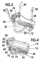
FIG. 3 is a perspective view of the outer knee pad structure of the exemplary embodiment of the knee pad assembly of FIG. 1 in isolation; also show are two representative securing straps.
FIG. 4 is a cross-sectional view of the exemplary embodiment of the knee pad assembly along the line 4—4 of FIG. 1 show is a perspective view of an exemplary embodiment of the knee pad assembly of the present invention showing the outer knee pad structure, the knee cap support spring, and the resilient foam inner knee pad structure.
FIG. 5 is a second cross-sectional view of the exemplary embodiment of the knee pad assembly of FIG. 1 configured for use without the knee cap support spring.
FIG. 6 is a top plan view of the outer knee pad structure of the exemplary embodiment of the knee pad assembly of FIG. 1 in isolation.
FIG. 7 is an underside perspective view of the outer knee pad structure of the exemplary embodiment of the knee pad assembly of FIG. 1 in isolation.
FIG. 8 is a perspective underside view of the outer knee pad structure of the exemplary embodiment of the knee.pad assembly of FIG. 1 in isolation showing the non-slip bottom surface.
FIG. 9 is a perspective view of a second exemplary embodiment of the outer knee pad structure of the knee pad assembly of the present invention showing a smooth bottom channel surface without any impact absorbing cavities.
FIGS. 1-8 show various aspects of an exemplary embodiment of the kneepad assembly of the present invention generally designated 10. Kneepad assembly knee pad system 10 includes an outer knee pad structure, generally designated 12; a knee cap support spring, generally designated 14; and a resilient foam inner knee and shin pad structure, generally designated 16.
Outer knee pad structure 12 being molded of plastic and including a bottom knee support plate, generally designated 18, having a non-slip bottom surface 20 and a top portion 22 integrally formed with a knee and shin receiving structure, generally designated 24, that defines an inner knee and shin pad receiving channel 28. Inner knee and shin pad receiving channel 28 is partially defined by a bottom channel surface 30 of knee and shin receiving structure 24 that has a number of impact absorbing cavities 32 and a spring bottom receiving channel 34 provided therein. Inner knee and shin pad receiving channel 28 is also partially defined by an accordion fold portion, generally designated 36 extending upwardly from a front end 40 of the bottom channel surface 30 and a pair of mirror image side wall assemblies, generally designated 48, 50 each extending from an opposite side edge 52, 54 of bottom channel surface 30 and each including along a rear top sidewall edge thereof a kneepad assembly retaining strap aperture 56 for receiving a securing strap 58 for retaining the rear portion of outer knee pad structure 12 adjacent to an upper shin of a user.
The accordion fold portion 36 includes a number of semi-circular accordion folds 51 and two spaced retaining strap apertures 60. Each of the two spaced retaining strap apertures 60 is provided for receiving a retaining strap 58 for retaining the accordion fold portion 36 of outer knee pad structure 12 adjacent to a knee of a user.
The resilient foam inner knee and shin pad structure 16 is shaped to seat into the inner knee and shin pad receiving channel 28 of the knee and shin receiving structure 12 and includes a top spring receiving channel 66 for receiving a top end 70 of knee cap support spring 14 when a bottom end 72 of knee cap support spring 14 is positioned within spring bottom receiving channel 34 of bottom channel surface 30.
FIG. 9 shows a second exemplary embodiment of the outer knee pad structure, generally designated 12 a, that has a smooth bottom channel surface 30 a that does not have the impact absorbing cavities 32 of outer knee pad structure 12.
In use, the user may use knee pad assembly 10 with or without knee cap support spring 14 or resilient foam inner knee and shin pad structure 16. Knee cap support spring 14 may be used alone with outer knee pad structure 12 or 12 a. Also, if desired, resilient foam inner knee and shin pad structure 16 may be used alone with outer knee pad structure 12 or 12 a by directly inserting resilient foam inner knee and shin pad structure 16 into inner knee and shin pad receiving channel 28 without any knee cap support spring 14. Additionally, two knee pad assemblies 10 may be used, one for each knee of the worker.
It is noted that the embodiment of the kneepad assembly knee pads system described herein in detail for exemplary purposes is of course subject to many different variations in structure, design, application and methodology. Because many varying and different embodiments may be made within the scope of the inventive concept(s) herein taught, and because many modifications may be made in the embodiment herein detailed in accordance with the descriptive requirements of the law, it is to be understood that the details herein are to be interpreted as illustrative and not in a limiting sense.
Claims (3)
1. A kneepad assembly comprising:
an outer knee pad structure molded of plastic and including a bottom knee support plate having a non-slip bottom surface and a top portion integrally formed with a knee and shin receiving structure that defines an inner knee and shin pad receiving channel;
the inner knee and shin pad receiving channel being partially defined by a bottom channel surface of the knee and shin receiving structure;
the inner knee and shin pad receiving channel being further partially defined by an accordion fold portion extending upwardly from a front end of the bottom channel surface;
the inner knee and shin pad receiving channel being still further partially defined by a pair of mirror image side wall assemblies each extending from an opposite side edge of the bottom channel surface and including along a rear top sidewall edge thereof a kneepad assembly retaining strap aperture for receiving a securing strap for retaining the rear portion of the outer knee pad structure adjacent to an upper shin of a user;
the accordion fold portion including two spaced retaining strap apertures, each of the two spaced retaining strap apertures being provided for receiving a retaining strap for retaining the accordion fold portion of the outer knee pad structure adjacent to a knee of a user wherein the bottom channel surface includes a spring bottom receiving channel defined therein; and wherein the kneepad assembly further comprises:
a knee cap support spring having a spring bottom sized and shaped to seat into the spring bottom receiving channel.
2. The kneepad assembly of claim 1 further comprising:
a resilient foam inner knee and shin pad structure shaped to seat into the inner knee and shin pad receiving channel of the knee and shin receiving structure.
3. A kneepad assembly comprising:
an outer knee pad structure;
a knee cap support spring; and
a resilient foam inner knee and shin pad structure;
the outer knee pad structure being molded of plastic and including a bottom knee support plate having a non-slip bottom surface and a top portion integrally formed with a knee and shin receiving structure that defines an inner knee and shin pad receiving channel;
the inner knee and shin pad receiving channel being partially defined by a bottom channel surface of the knee and shin receiving structure;
the inner knee and shin pad receiving channel being further partially defined by an accordion fold portion extending upwardly from a front end of the bottom channel surface;
the inner knee and shin pad receiving channel being still further partially defined by a pair of mirror image side wall assemblies each extending from an opposite side edge of the bottom a channel surface and including along a rear top sidewall edge thereof a kneepad assembly retaining strap aperture for receiving a securing strap for retaining the rear portion of the outer knee pad structure adjacent to an upper shin of a user;
the accordion fold portion including two spaced retaining strap apertures, each of the two spaced retaining strap apertures being provided for receiving a retaining strap for retaining the accordion fold portion of the outer knee pad structure adjacent to a knee of a user;
the resilient foam inner knee and shin pad structure being shaped to seat into the inner knee and shin pad receiving channel of the knee and shin receiving structure and including a top spring receiving channel for receiving a top end of the knee cap support spring when a bottom end of the knee cap support spring is positioned within a spring bottom receiving channel of the bottom channel surface.
Priority Applications (3)
| Application Number | Priority Date | Filing Date | Title |
|---|---|---|---|
| US10/108,050 US6807682B1 (en) | 2002-03-28 | 2002-03-28 | Kneepad assembly |
| US10/434,728 US7062787B1 (en) | 2002-03-28 | 2003-05-09 | Kneepad assembly |
| US11/453,217 US20070017005A1 (en) | 2002-03-28 | 2006-06-15 | Kneepad assembly |
Applications Claiming Priority (1)
| Application Number | Priority Date | Filing Date | Title |
|---|---|---|---|
| US10/108,050 US6807682B1 (en) | 2002-03-28 | 2002-03-28 | Kneepad assembly |
Related Child Applications (1)
| Application Number | Title | Priority Date | Filing Date |
|---|---|---|---|
| US10/434,728 Continuation-In-Part US7062787B1 (en) | 2002-03-28 | 2003-05-09 | Kneepad assembly |
Publications (1)
| Publication Number | Publication Date |
|---|---|
| US6807682B1 true US6807682B1 (en) | 2004-10-26 |
Family
ID=33158029
Family Applications (3)
| Application Number | Title | Priority Date | Filing Date |
|---|---|---|---|
| US10/108,050 Expired - Fee Related US6807682B1 (en) | 2002-03-28 | 2002-03-28 | Kneepad assembly |
| US10/434,728 Expired - Fee Related US7062787B1 (en) | 2002-03-28 | 2003-05-09 | Kneepad assembly |
| US11/453,217 Abandoned US20070017005A1 (en) | 2002-03-28 | 2006-06-15 | Kneepad assembly |
Family Applications After (2)
| Application Number | Title | Priority Date | Filing Date |
|---|---|---|---|
| US10/434,728 Expired - Fee Related US7062787B1 (en) | 2002-03-28 | 2003-05-09 | Kneepad assembly |
| US11/453,217 Abandoned US20070017005A1 (en) | 2002-03-28 | 2006-06-15 | Kneepad assembly |
Country Status (1)
| Country | Link |
|---|---|
| US (3) | US6807682B1 (en) |
Cited By (13)
| Publication number | Priority date | Publication date | Assignee | Title |
|---|---|---|---|---|
| US20070017005A1 (en) * | 2002-03-28 | 2007-01-25 | Shircliff David E | Kneepad assembly |
| US20100095440A1 (en) * | 2008-10-17 | 2010-04-22 | Bigalke Jerry H | Knee-mounted air deflector for motorcyclist |
| US20120260392A1 (en) * | 2011-04-14 | 2012-10-18 | Thomas Votel | Knee pad |
| WO2015128672A1 (en) * | 2014-02-28 | 2015-09-03 | Victoria Hamilton | Protection device |
| USD763517S1 (en) * | 2015-06-23 | 2016-08-09 | Urbano Cavazos | Kneepad with removable joist support |
| WO2018119129A1 (en) * | 2016-12-23 | 2018-06-28 | Boswell Steven M | Support for demolition devices |
| USD823546S1 (en) * | 2017-09-20 | 2018-07-17 | James Petroff | Shin pad |
| US20180213857A1 (en) * | 2017-01-31 | 2018-08-02 | Q.E.P.Co., Inc. | Protective kneepad with memory interior |
| US11166499B2 (en) | 2018-10-16 | 2021-11-09 | Greg Vescovi | Joint pad assembly |
| US11412788B2 (en) * | 2020-08-11 | 2022-08-16 | Ana Maria Teixeira Rangel | Wearable liquid silicone rubber product |
| USD973970S1 (en) * | 2020-04-02 | 2022-12-27 | Milwaukee Electric Tool Corporation | Knee pad |
| US20230354928A1 (en) * | 2021-04-06 | 2023-11-09 | Ana Maria Teixeira Rangel | Configuration in product made with rubber liquid silicone (lsr) intended for comfort, protection, rehabilitation and body care |
| USD1025498S1 (en) | 2022-12-02 | 2024-04-30 | Milwaukee Electric Tool Corporation | Knee pad |
Families Citing this family (3)
| Publication number | Priority date | Publication date | Assignee | Title |
|---|---|---|---|---|
| US7448088B2 (en) * | 2006-06-22 | 2008-11-11 | Custom Building Products, Inc. | Knee pad |
| US8621666B2 (en) | 2009-02-04 | 2014-01-07 | Lineweight Llc | Garment protective assembly |
| US9433247B1 (en) * | 2015-04-01 | 2016-09-06 | Stephen John Harris | Weight-displacing knee pad |
Citations (13)
| Publication number | Priority date | Publication date | Assignee | Title |
|---|---|---|---|---|
| US573919A (en) * | 1896-12-29 | Knee-pad | ||
| US909215A (en) * | 1908-10-13 | 1909-01-12 | Spalding & Bros Ag | Leg-guard for athletes. |
| US1293240A (en) * | 1917-02-06 | 1919-02-04 | Paul J Summers | Knee-pad. |
| US1560825A (en) * | 1923-03-23 | 1925-11-10 | Kelticka Ludwig | Protective device for knees, etc. |
| US1753055A (en) * | 1928-04-02 | 1930-04-01 | Matheson Roy | Knee pad |
| US1785213A (en) * | 1930-08-12 | 1930-12-16 | Shotwell Joseph Emsley | Knee pad |
| US2640989A (en) * | 1950-06-01 | 1953-06-09 | Eureka Rubber Co North Ltd | Limb protector or guard |
| US4642814A (en) * | 1985-11-01 | 1987-02-17 | Godfrey Jerry W | Athletic padding |
| US5031240A (en) * | 1990-03-14 | 1991-07-16 | Friedr. Nierhaus & Co. | Kneepad |
| US5269322A (en) * | 1992-11-09 | 1993-12-14 | Edward Mandel | Lower back and spinal stress reducer apparatus |
| US5297294A (en) * | 1993-03-15 | 1994-03-29 | Washick Steven R | Shin guard having kneeshield, accordian pleated flexure area, flexure grooves and ventilation apertures |
| US5594954A (en) * | 1996-03-11 | 1997-01-21 | Huang; Cheng-Yen | Knee-pad and elbow-pad |
| USD408596S (en) * | 1997-01-22 | 1999-04-20 | Michael Dancyger | Kneepad |
Family Cites Families (12)
| Publication number | Priority date | Publication date | Assignee | Title |
|---|---|---|---|---|
| US1372790A (en) * | 1921-03-29 | Knee-pkotectoe | ||
| US1055040A (en) * | 1912-05-18 | 1913-03-04 | William Patrick Herron | Knee-pad for cotton-pickers, &c. |
| US2759189A (en) * | 1954-06-08 | 1956-08-21 | Ralph M Cole | Knee pad |
| US3112812A (en) * | 1961-11-24 | 1963-12-03 | Ramon Gino | Knee rest |
| US3411222A (en) * | 1965-08-30 | 1968-11-19 | Kathryn I. Williams | Methods and apparatus for instruction of cross pattern crawling and cross pattern walking |
| US4287885A (en) * | 1979-12-06 | 1981-09-08 | Surgical Appliance Industries, Inc. | Knee brace with resilient pad surrounding patella |
| US4723322A (en) * | 1987-03-16 | 1988-02-09 | Spenco Medical Corporation | Knee pad |
| CA2001893C (en) * | 1989-10-31 | 1996-12-03 | Philip J. R. Mcelroy | Air cushion kneeling pad |
| US5524292A (en) * | 1994-10-14 | 1996-06-11 | Hargens; Michael | Knee pad unit |
| US5870774A (en) * | 1997-08-29 | 1999-02-16 | Legenstein; Mark P. | Rolling knee pad |
| US6584616B2 (en) * | 2001-07-10 | 2003-07-01 | Travel Caddy, Inc. | Knee pad construction |
| US6807682B1 (en) * | 2002-03-28 | 2004-10-26 | David E. Shircliff | Kneepad assembly |
-
2002
- 2002-03-28 US US10/108,050 patent/US6807682B1/en not_active Expired - Fee Related
-
2003
- 2003-05-09 US US10/434,728 patent/US7062787B1/en not_active Expired - Fee Related
-
2006
- 2006-06-15 US US11/453,217 patent/US20070017005A1/en not_active Abandoned
Patent Citations (13)
| Publication number | Priority date | Publication date | Assignee | Title |
|---|---|---|---|---|
| US573919A (en) * | 1896-12-29 | Knee-pad | ||
| US909215A (en) * | 1908-10-13 | 1909-01-12 | Spalding & Bros Ag | Leg-guard for athletes. |
| US1293240A (en) * | 1917-02-06 | 1919-02-04 | Paul J Summers | Knee-pad. |
| US1560825A (en) * | 1923-03-23 | 1925-11-10 | Kelticka Ludwig | Protective device for knees, etc. |
| US1753055A (en) * | 1928-04-02 | 1930-04-01 | Matheson Roy | Knee pad |
| US1785213A (en) * | 1930-08-12 | 1930-12-16 | Shotwell Joseph Emsley | Knee pad |
| US2640989A (en) * | 1950-06-01 | 1953-06-09 | Eureka Rubber Co North Ltd | Limb protector or guard |
| US4642814A (en) * | 1985-11-01 | 1987-02-17 | Godfrey Jerry W | Athletic padding |
| US5031240A (en) * | 1990-03-14 | 1991-07-16 | Friedr. Nierhaus & Co. | Kneepad |
| US5269322A (en) * | 1992-11-09 | 1993-12-14 | Edward Mandel | Lower back and spinal stress reducer apparatus |
| US5297294A (en) * | 1993-03-15 | 1994-03-29 | Washick Steven R | Shin guard having kneeshield, accordian pleated flexure area, flexure grooves and ventilation apertures |
| US5594954A (en) * | 1996-03-11 | 1997-01-21 | Huang; Cheng-Yen | Knee-pad and elbow-pad |
| USD408596S (en) * | 1997-01-22 | 1999-04-20 | Michael Dancyger | Kneepad |
Cited By (18)
| Publication number | Priority date | Publication date | Assignee | Title |
|---|---|---|---|---|
| US20070017005A1 (en) * | 2002-03-28 | 2007-01-25 | Shircliff David E | Kneepad assembly |
| US20100095440A1 (en) * | 2008-10-17 | 2010-04-22 | Bigalke Jerry H | Knee-mounted air deflector for motorcyclist |
| US8127369B2 (en) * | 2008-10-17 | 2012-03-06 | Bigalke Jerry H | Knee-mounted air deflector for motorcyclist |
| US20120260392A1 (en) * | 2011-04-14 | 2012-10-18 | Thomas Votel | Knee pad |
| AU2015221952B2 (en) * | 2014-02-28 | 2020-03-12 | Victoria Hamilton | Protection device |
| WO2015128672A1 (en) * | 2014-02-28 | 2015-09-03 | Victoria Hamilton | Protection device |
| US20170013893A1 (en) * | 2014-02-28 | 2017-01-19 | Victoria HAMILTON | Protection device |
| US10441008B2 (en) | 2014-02-28 | 2019-10-15 | Victoria HAMILTON | Protection device |
| USD763517S1 (en) * | 2015-06-23 | 2016-08-09 | Urbano Cavazos | Kneepad with removable joist support |
| WO2018119129A1 (en) * | 2016-12-23 | 2018-06-28 | Boswell Steven M | Support for demolition devices |
| US10493612B2 (en) | 2016-12-23 | 2019-12-03 | Steven M. BOSWELL | Support for demolition devices |
| US20180213857A1 (en) * | 2017-01-31 | 2018-08-02 | Q.E.P.Co., Inc. | Protective kneepad with memory interior |
| USD823546S1 (en) * | 2017-09-20 | 2018-07-17 | James Petroff | Shin pad |
| US11166499B2 (en) | 2018-10-16 | 2021-11-09 | Greg Vescovi | Joint pad assembly |
| USD973970S1 (en) * | 2020-04-02 | 2022-12-27 | Milwaukee Electric Tool Corporation | Knee pad |
| US11412788B2 (en) * | 2020-08-11 | 2022-08-16 | Ana Maria Teixeira Rangel | Wearable liquid silicone rubber product |
| US20230354928A1 (en) * | 2021-04-06 | 2023-11-09 | Ana Maria Teixeira Rangel | Configuration in product made with rubber liquid silicone (lsr) intended for comfort, protection, rehabilitation and body care |
| USD1025498S1 (en) | 2022-12-02 | 2024-04-30 | Milwaukee Electric Tool Corporation | Knee pad |
Also Published As
| Publication number | Publication date |
|---|---|
| US7062787B1 (en) | 2006-06-20 |
| US20070017005A1 (en) | 2007-01-25 |
Similar Documents
| Publication | Publication Date | Title |
|---|---|---|
| US6807682B1 (en) | Kneepad assembly | |
| US6401245B1 (en) | Knee pad and manufacturing method | |
| US6223350B1 (en) | Molded knee pad construction | |
| US7181770B2 (en) | Knee pad construction | |
| US9867408B2 (en) | Knee pad device | |
| US5575139A (en) | Non-slip saddle pad | |
| US8201796B2 (en) | Corner protector | |
| US9433247B1 (en) | Weight-displacing knee pad | |
| US20070074932A1 (en) | Padding device for use with ladders | |
| US20120227150A1 (en) | Knee pad | |
| US5309570A (en) | Knee pad | |
| US6415890B1 (en) | Padded ladder protector | |
| US6415441B1 (en) | Knee protecting device | |
| US20020046904A1 (en) | Ladder pad device | |
| US7409725B1 (en) | Knee protecting apparatus | |
| WO1994018861A1 (en) | A knee or elbow guard | |
| US7299506B1 (en) | Bedsore prevention kit | |
| KR102022834B1 (en) | Portable toilet seat having reinforced stability | |
| WO2017205861A1 (en) | Knee pad apparatus with enhanced cushion and interchangeable outer shell | |
| US20100012428A1 (en) | End cover for a ladder rail | |
| US6032913A (en) | Computer mouse support system | |
| US20050120456A1 (en) | Kneepad having an ergonomic notch | |
| KR20140005915U (en) | Multi-function Notebook case | |
| KR20180086793A (en) | Earthquake head guards and a cushion | |
| US6763913B1 (en) | Cover apparatus |
Legal Events
| Date | Code | Title | Description |
|---|---|---|---|
| REFU | Refund |
Free format text: REFUND - SURCHARGE, PETITION TO ACCEPT PYMT AFTER EXP, UNINTENTIONAL (ORIGINAL EVENT CODE: R2551); ENTITY STATUS OF PATENT OWNER: SMALL ENTITY Free format text: REFUND - SURCHARGE FOR LATE PAYMENT, SMALL ENTITY (ORIGINAL EVENT CODE: R2554); ENTITY STATUS OF PATENT OWNER: SMALL ENTITY |
|
| REMI | Maintenance fee reminder mailed | ||
| FPAY | Fee payment |
Year of fee payment: 4 |
|
| SULP | Surcharge for late payment | ||
| REMI | Maintenance fee reminder mailed | ||
| LAPS | Lapse for failure to pay maintenance fees | ||
| STCH | Information on status: patent discontinuation |
Free format text: PATENT EXPIRED DUE TO NONPAYMENT OF MAINTENANCE FEES UNDER 37 CFR 1.362 |
|
| FP | Lapsed due to failure to pay maintenance fee |
Effective date: 20121026 |