US6824075B2 - Spray gun - Google Patents

Spray gun Download PDF

Info

Publication number
US6824075B2
US6824075B2 US10/460,905 US46090503A US6824075B2 US 6824075 B2 US6824075 B2 US 6824075B2 US 46090503 A US46090503 A US 46090503A US 6824075 B2 US6824075 B2 US 6824075B2
Authority
US
United States
Prior art keywords
valve needle
guide sleeve
spray gun
seal
housing
Prior art date
Legal status (The legal status is an assumption and is not a legal conclusion. Google has not performed a legal analysis and makes no representation as to the accuracy of the status listed.)
Expired - Lifetime, expires
Application number
US10/460,905
Other versions
US20040026534A1 (en
Inventor
Guido Zimmermann
Current Assignee (The listed assignees may be inaccurate. Google has not performed a legal analysis and makes no representation or warranty as to the accuracy of the list.)
J Wagner GmbH
Original Assignee
J Wagner GmbH
Priority date (The priority date is an assumption and is not a legal conclusion. Google has not performed a legal analysis and makes no representation as to the accuracy of the date listed.)
Filing date
Publication date
Family has litigation
First worldwide family litigation filed litigation Critical https://patents.darts-ip.com/?family=29557847&utm_source=google_patent&utm_medium=platform_link&utm_campaign=public_patent_search&patent=US6824075(B2) "Global patent litigation dataset” by Darts-ip is licensed under a Creative Commons Attribution 4.0 International License.
Application filed by J Wagner GmbH filed Critical J Wagner GmbH
Assigned to J. WAGNER GMBH reassignment J. WAGNER GMBH ASSIGNMENT OF ASSIGNORS INTEREST (SEE DOCUMENT FOR DETAILS). Assignors: ZIMMERMANN, GUIDO
Publication of US20040026534A1 publication Critical patent/US20040026534A1/en
Application granted granted Critical
Publication of US6824075B2 publication Critical patent/US6824075B2/en
Adjusted expiration legal-status Critical
Expired - Lifetime legal-status Critical Current

Links

Images

Classifications

    • BPERFORMING OPERATIONS; TRANSPORTING
    • B05SPRAYING OR ATOMISING IN GENERAL; APPLYING FLUENT MATERIALS TO SURFACES, IN GENERAL
    • B05BSPRAYING APPARATUS; ATOMISING APPARATUS; NOZZLES
    • B05B12/00Arrangements for controlling delivery; Arrangements for controlling the spray area
    • B05B12/002Manually-actuated controlling means, e.g. push buttons, levers or triggers
    • B05B12/0022Manually-actuated controlling means, e.g. push buttons, levers or triggers associated with means for restricting their movement
    • BPERFORMING OPERATIONS; TRANSPORTING
    • B05SPRAYING OR ATOMISING IN GENERAL; APPLYING FLUENT MATERIALS TO SURFACES, IN GENERAL
    • B05BSPRAYING APPARATUS; ATOMISING APPARATUS; NOZZLES
    • B05B1/00Nozzles, spray heads or other outlets, with or without auxiliary devices such as valves, heating means
    • B05B1/30Nozzles, spray heads or other outlets, with or without auxiliary devices such as valves, heating means designed to control volume of flow, e.g. with adjustable passages
    • B05B1/3033Nozzles, spray heads or other outlets, with or without auxiliary devices such as valves, heating means designed to control volume of flow, e.g. with adjustable passages the control being effected by relative coaxial longitudinal movement of the controlling element and the spray head
    • B05B1/304Nozzles, spray heads or other outlets, with or without auxiliary devices such as valves, heating means designed to control volume of flow, e.g. with adjustable passages the control being effected by relative coaxial longitudinal movement of the controlling element and the spray head the controlling element being a lift valve
    • B05B1/3046Nozzles, spray heads or other outlets, with or without auxiliary devices such as valves, heating means designed to control volume of flow, e.g. with adjustable passages the control being effected by relative coaxial longitudinal movement of the controlling element and the spray head the controlling element being a lift valve the valve element, e.g. a needle, co-operating with a valve seat located downstream of the valve element and its actuating means, generally in the proximity of the outlet orifice
    • BPERFORMING OPERATIONS; TRANSPORTING
    • B05SPRAYING OR ATOMISING IN GENERAL; APPLYING FLUENT MATERIALS TO SURFACES, IN GENERAL
    • B05BSPRAYING APPARATUS; ATOMISING APPARATUS; NOZZLES
    • B05B12/00Arrangements for controlling delivery; Arrangements for controlling the spray area
    • B05B12/002Manually-actuated controlling means, e.g. push buttons, levers or triggers
    • BPERFORMING OPERATIONS; TRANSPORTING
    • B05SPRAYING OR ATOMISING IN GENERAL; APPLYING FLUENT MATERIALS TO SURFACES, IN GENERAL
    • B05BSPRAYING APPARATUS; ATOMISING APPARATUS; NOZZLES
    • B05B7/00Spraying apparatus for discharge of liquids or other fluent materials from two or more sources, e.g. of liquid and air, of powder and gas
    • B05B7/24Spraying apparatus for discharge of liquids or other fluent materials from two or more sources, e.g. of liquid and air, of powder and gas with means, e.g. a container, for supplying liquid or other fluent material to a discharge device
    • B05B7/2402Apparatus to be carried on or by a person, e.g. by hand; Apparatus comprising containers fixed to the discharge device
    • B05B7/2405Apparatus to be carried on or by a person, e.g. by hand; Apparatus comprising containers fixed to the discharge device using an atomising fluid as carrying fluid for feeding, e.g. by suction or pressure, a carried liquid from the container to the nozzle
    • B05B7/2435Apparatus to be carried on or by a person, e.g. by hand; Apparatus comprising containers fixed to the discharge device using an atomising fluid as carrying fluid for feeding, e.g. by suction or pressure, a carried liquid from the container to the nozzle the carried liquid and the main stream of atomising fluid being brought together by parallel conduits placed one inside the other
    • B05B7/2437Apparatus to be carried on or by a person, e.g. by hand; Apparatus comprising containers fixed to the discharge device using an atomising fluid as carrying fluid for feeding, e.g. by suction or pressure, a carried liquid from the container to the nozzle the carried liquid and the main stream of atomising fluid being brought together by parallel conduits placed one inside the other and a secondary stream of atomising fluid being brought together in the container or putting the carried fluid under pressure in the container

Landscapes

  • Nozzles (AREA)
  • Particle Formation And Scattering Control In Inkjet Printers (AREA)
  • Coating By Spraying Or Casting (AREA)

Abstract

A spray gun for atomizing fluid with compressed air comprises a housing having a handle, an atomizer nozzle, a guide sleeve having a U-shaped cross section which engages in the atomizer nozzle and is supported in the housing, and a valve needle which can be operated by means of a trigger which is in a pivoting mounting. The valve needle is connected with the trigger in the area of the guide sleeve by means of a hinge pin. A seal disposed in the guide sleeve, the seal being located between a feed line and the hinge pin, with the valve needle being held in a movable arrangement in the seal.

Description

The present invention relates to a spray gun for atomizing fluid media with the help of compressed air, principally consisting of a housing with a handle and an atomizer nozzle which can be connected to a compressed air line, of a guide sleeve supported in the housing equipped with a feed line for the medium to be atomized, with one end of the guide sleeve engaging in the atomizer nozzle, as well as of a valve needle which can be operated against the force of a return spring in order to open the atomizer nozzle by means of a trigger handle which is in a pivoting mounting on the housing.
There are numerous different embodiments of spray guns of prior art which have also proven themselves to be effective in practice. In such embodiments, the valve needle projects out of the guide sleeve on the side facing away from the atomizer nozzle and also out of the housing of the spray gun, while a trigger handle in a pivoting mounting on the housing acts on the spray gun. The valve needle has a special seal in the guide sleeve to prevent the medium to be applied from leaking out of the interior of the guide sleeve. This is achieved in that a deformable seal is clamped in between the valve needle and the guide sleeve by means of a further sleeve which can be screwed into the guide sleeve.
Assembling the valve needle in the guide sleeve is difficult and time-consuming, since the clamping force which acts on the seal must be set exactly. This is because, if the preload on the seal is too great, the valve needle can only be moved by applying considerable force to it, while on the other hand if the preload is insufficient then there is a significant risk that medium will leak out during operation through the two ring gaps which are to be sealed. The stuffing gland arranged in the guide sleeve therefore represents a degree of uncertainty as far as achieving a correct seal is concerned. Furthermore, the seal is a considerable cost factor, since the stuffing gland is assembled from several interacting components which are subject to wear and also have to be replaced from time to time.
The purpose of the present invention is therefore to create a spray gun of the aforementioned type in such a way that straightforward assembly of the valve needle is possible within a short period of time and that a reliable means is provided to prevent the medium leaking out from the interior of the guide sleeve. The construction complexity by which this is to be achieved should be kept at a low level, therefore permitting economical manufacture and assembly of the spray gun. Also, the susceptibility to faults should be reduced over a long service life.
In the present invention, this is achieved in a spray gun in accordance with the pre-characterizing clause of claim 1 in that the valve needle is located in a positive connection with the trigger handle in the area of the guide sleeve by means of a hinge pin which passes through the valve needle and the guide sleeve and that a seal is inserted in the guide sleeve with a U-shaped cross section, the seal being located between the feed line and the hinge pin, with the valve needle being held in a movable arrangement in the seal.
It is advantageous in this arrangement for the valve needle to be provided with a thickened portion in the area of a bore which accommodates the hinge pin, with the thickened portion being adapted to the internal jacket surface of the guide sleeve, and for the valve needle to be provided with a collar in the end area facing away from the atomizer nozzle, serving as a stop for the return spring which is inserted in between the collar and a base of the guide sleeve.
The seal which accommodates the valve needle should be equipped with one or more lugs projecting along the length of the valve needle on one of its two sides, with each of the lugs having a slot and with projections formed on the valve needle engaging in the slots or between two lugs.
For the purpose of positionally-oriented assembly of the valve needle, it is furthermore advantageous for one or more, or in a preferred embodiment two, diametrically opposed contact surfaces to be formed onto the valve needle, in which case the contact surfaces should be worked into the valve needle between the tip of the valve needle and the seal which holds it.
The guide sleeve can be held in a partition wall of the housing in a straightforward way and be used to provide a seal in the atomizer nozzle with the help of a lip seal, as well as being supported axially on the partition wall of the housing by means of a stop surface.
Furthermore, it is advantageous for the valve needle to be made in one piece from plastic.
If a spray gun is configured in accordance with the present invention, then not only will reliable operation be assured at all times, but also the valve needle can be installed in the guide sleeve in a positionally-oriented manner without difficulty and excluding the possibility of the medium to be applied leaking out. This is because an assembly tool can be used to insert the valve needle together with the seal through which it is inserted and the return spring into the guide sleeve which is closed at one end, with the aforementioned components being inserted in such a way that the hinge pin by means of which the valve needle is held in a positive connection with the trigger handle can be installed without difficulty. There is no need to clamp special seals in this embodiment, and also only a few components are required to enable the stored medium to be applied in a metered fashion.
Economical production is possible since nearly all components, in particular also the single-piece valve needle, can be manufactured from plastic. Furthermore, the design ensures that malfunctions and wear to the few components which are to be moved during operation are practically excluded, so therefore the spray gun configured in accordance with the proposed invention can be guaranteed to achieve a lengthy service life.
The drawing shows a sample embodiment of a spray gun configured in accordance with the present invention, the details of which are explained below. In the drawing, the figures of which all show axial sections,
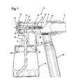
FIG. 1 shows the spray gun with all its components,
FIG. 2 shows a section through the spray gun in accordance with FIG. 1 in a magnified view, and
FIGS. 3 and 4 show the valve needle used in the spray gun in accordance with FIG. 1, in different installation positions.
The spray gun shown in FIG. 1 and identified with the number 1 is used for atomizing fluid media by means of compressed air and its principal components include a pistol-shaped housing 11 on which a handle 14 and a joining piece 15 for holding a reservoir tank 18 are formed, an atomizer nozzle 19 screwed onto the housing 11 at one end by means of a union nut 20 and a valve needle 31 which is arranged in a movable location in a guide sleeve 21. The housing 11 has a compressed air line 2 connected to it from which compressed air flows into the interior 12 of the housing 11 and flows out through ducts 30 provided in the atomizer nozzle 19. When the atomizer nozzle 19 is open, the medium to be applied is drawn from the interior 22 of the atomizer nozzle 19 and is atomized.
The guide sleeve 21 has a U-shaped cross section and is held in a partition wall 13 of the housing 11 as well as in the atomizer nozzle 19. To this end, a contact surface 24 is formed onto the guide sleeve 21, by means of which the guide sleeve 21 is supported against the partition wall 13, and a lip seal 25 is placed on the end of the guide sleeve 21 facing away from the atomizer nozzle 19, so that the medium from the interior 22 of the guide sleeve 21 can only emerge via the atomizer nozzle 19.
The medium to be applied flows into the interior 22 of the guide sleeve 21 via a feed line 16 which is formed in the joining piece 15 onto which a reservoir tank 18 is screwed. To achieve this, a line 17 or a bore 18″ is worked into the joining piece 16 as well as into a seal 18′ lying on the tank 18, with the interior of the tank 18 being connected to the interior 12 of the housing 11 by means of the line 17 or the bore 18″. As a result, compressed air acts on the medium in the tank 18, forcing it into the interior 22 of the guide sleeve 21.
A trigger handle 26 is provided to activate the valve needle 31 inserted in the guide sleeve 21, this trigger handle 26 being held in a pivoting mounting in the housing 11 by means of a hinge pin 27 and in a positive connection with the valve needle by means of a further hinge pin 27′. There is a thickened portion 34 formed on the valve needle 31 for this purpose and a bore 35 is provided in the thickened portion 34 in order to accommodate the hinge pin 27′. In addition, an axially aligned slot 29 is worked into the housing 11 on both sides in the area of the hinge pin 27′, so that the hinge pin 27′ can be moved in accordance with the movement of the trigger handle 26 which has a stop 28 associated with it for setting and limiting the movement.
As can be seen in particular in FIGS. 3 and 4, the valve needle 31 is provided with two diametrically opposed contact surfaces 37, with the effect that the valve needle 31, together with a seal 32 placed thereupon, can be installed in the guide sleeve 21 in a positionally-oriented manner using an assembly fixture. A return spring 33 is installed in the guide sleeve 21 prior to this, the return spring 33 resting on a base 23 of the guide sleeve 21 and against a collar 36 formed onto the valve needle 31. When opening the atomizer nozzle 19, it is necessary to use the trigger handle 26 to overcome the force of the return spring 33; as soon as no more force is applied to the trigger handle 26, the atomizer nozzle 19 into which the tip 31′ of the valve needle 31 projects is automatically closed by means of the return spring 33.
Two formed lugs 38 with slots 39 in them are provided to hold the seal 32 in which the valve needle 31 is inserted in an axially movable arrangement. Projections 40 emerging radially from the valve needle 31 engage in the slots 39 or between the two lugs 38. In this way, it is assured that the seal 32 remains in the assigned position even when the valve needle 31 is moved. Furthermore, the seal 32 ensures that no medium can leak from the interior 22 of the guide sleeve 21 and reach the hinge pin 27′, or can emerge from the bore 35 in the valve needle 31 as well as from the slots 29 worked into the housing 11.

Claims (9)

What is claimed is:
1. A spray gun (1) for atomizing fluid with compressed air, the spray gun comprising a housing (11), a handle (14) fixed to said housing, an atomizer nozzle (19) which is placed in communication with a compressed air line (2), a guide sleeve (21) supported in said housing (11) and provided with a feed line (16) for the fluid to be atomized, with one end of said guide sleeve (21) engaging in said atomizer nozzle (19), and a valve needle (31) which can be operated against the force of a return spring (33) in order to open said atomizer nozzle (19) by means of a trigger (26) pivotally mounted on said housing (11), wherein said valve needle (31) is connected to the trigger (26) in an area of said guide sleeve (21) by means of a hinge pin (27′) which passes through said valve needle (31) and said guide sleeve (21), and wherein a seal (32) is disposed in said guide sleeve (21 ), which is provided with a U-shaped cross section, the seal (32) being located between the feed line (16) and the hinge pin (27′), with said valve needle (31) being held in a movable arrangement in the seal (32).
2. The spray gun in accordance with claim 1, wherein said valve needle (31) is provided with a thickened portion (34) in an area of a bore (35) which accommodates the hinge pin (27′), the thickened portion (34) being complementary to an internal surface of said guide sleeve (21).
3. The spray gun in accordance with claim 1, wherein said valve needle (31) is provided with a collar (36) in an end area removed from said atomizer nozzle (19), the collar serving as a stop for the return spring (33) which is disposed between the collar (36) and a base (23) of said guide sleeve (21).
4. The spray gun in accordance with claim 1, wherein the seal (32) accommodates said valve needle (31) and is provided with lugs (38) projecting along the length of said valve needle (31) on both sides, each of the lugs (38) having a slot (39), and projections (40) formed on said valve needle (31) and engaging in at least one of the slots (39) and between two of the lugs (38).
5. The spray gun in accordance with claim 1, wherein said valve needle (31) comprises diametrically opposed contact surfaces (37) formed on said valve needle (31).
6. The spray gun in accordance with claim 5, wherein the contact surfaces (37) on said valve needle (31) are disposed between a tip (31′) of said valve needle (31) and the seal (32).
7. The spray gun in accordance with claim 1, wherein said guide sleeve (21) is held in a partition wall (13) of said housing (11).
8. The spray gun in accordance with claim 7, wherein a lip seal (25) is mounted on said guide sleeve (21) to provide a seal in said atomizer nozzle (19), and said guide sleeve is supported axially on the partition wall (13) of said housing (11) by means of a stop surface (24).
9. The spray gun in accordance with claim 1, wherein said valve needle (31) comprises a single unitary piece of plastic.
US10/460,905 2002-06-15 2003-06-13 Spray gun Expired - Lifetime US6824075B2 (en)

Applications Claiming Priority (3)

Application Number Priority Date Filing Date Title
DE10226792 2002-06-15
DE10226792.8-51 2002-06-15
DE10226792A DE10226792B4 (en) 2002-06-15 2002-06-15 spray gun

Publications (2)

Publication Number Publication Date
US20040026534A1 US20040026534A1 (en) 2004-02-12
US6824075B2 true US6824075B2 (en) 2004-11-30

Family

ID=29557847

Family Applications (1)

Application Number Title Priority Date Filing Date
US10/460,905 Expired - Lifetime US6824075B2 (en) 2002-06-15 2003-06-13 Spray gun

Country Status (4)

Country Link
US (1) US6824075B2 (en)
EP (1) EP1371421B1 (en)
AT (1) ATE290929T1 (en)
DE (2) DE10226792B4 (en)

Cited By (11)

* Cited by examiner, † Cited by third party
Publication number Priority date Publication date Assignee Title
US20060192026A1 (en) * 2005-02-25 2006-08-31 Majed Noujaim Combustion head for use with a flame spray apparatus
US20110089261A1 (en) * 2006-02-11 2011-04-21 Goehring Alfred Spray gun assembly
US20110114749A1 (en) * 2009-11-17 2011-05-19 Munn Jamie S Paint sprayer
US20110114760A1 (en) * 2009-11-17 2011-05-19 Munn Jamie S Paint sprayer
US20110114757A1 (en) * 2009-11-17 2011-05-19 Munn Jamie S Paint sprayer
US20110198412A1 (en) * 2009-11-17 2011-08-18 Munn Jamie S Paint sprayer
RU2495727C2 (en) * 2008-02-25 2013-10-20 Роберт Бош Гмбх Sprayer gun
US8651402B2 (en) 2009-11-17 2014-02-18 Black & Decker Inc. Adjustable nozzle tip for paint sprayer
US9149822B2 (en) 2009-11-17 2015-10-06 Black & Decker Inc. Quick release mechanism for paint sprayer
US20170320078A1 (en) * 2016-05-09 2017-11-09 The Sherwin-Williams Company Sprayer
US11413635B2 (en) 2018-10-26 2022-08-16 Graco Minnesota Inc. Mix chamber for a plural component sprayer

Families Citing this family (4)

* Cited by examiner, † Cited by third party
Publication number Priority date Publication date Assignee Title
DE102004024147A1 (en) * 2004-05-14 2005-12-08 L + N Plast Vertriebs Gmbh Small paint spray gun used in model construction has nozzle mechanism having valve movable to open and close air inflow channel and connect and disconnect color inflow channel and color outflow channel
DE102011013071A1 (en) * 2011-03-04 2012-09-20 Martin Ruda Spray gun with a Farbleitbereich and a paint needle
DE102013210539A1 (en) * 2013-06-06 2014-12-11 Heraeus Medical Gmbh Medical spray device with nozzle and method for generating a spray cone
US11950677B2 (en) 2019-02-28 2024-04-09 L'oreal Devices and methods for electrostatic application of cosmetics

Citations (12)

* Cited by examiner, † Cited by third party
Publication number Priority date Publication date Assignee Title
GB139833A (en) 1918-05-25 1920-03-18 Paolo Corti Improvements in compressed air spraying devices
US3032277A (en) * 1959-07-27 1962-05-01 Sherwin Williams Co Spray gun for multicolor paints
US3746253A (en) * 1970-09-21 1973-07-17 Walberg & Co A Coating system
DE3518492C2 (en) 1985-05-23 1987-12-17 Kopperschmidt-Mueller Gmbh & Co Kg, 4800 Bielefeld, De
US5671888A (en) * 1994-07-06 1997-09-30 Smith; Paul Spray gun with barrel-mounted venturi
US5685482A (en) * 1993-08-09 1997-11-11 Sickles; James E. Induction spray charging apparatus
US5727736A (en) * 1995-08-09 1998-03-17 Homax Products, Inc. Spray applicator with air shut-off valve
USRE35769E (en) * 1992-05-27 1998-04-14 Ransburg Corporation Spray gun having trigger overtravel protection and maximum flow adjustment knob warning
US5803372A (en) * 1997-04-03 1998-09-08 Asahi Sunac Corporation Hand held rotary atomizer spray gun
DE19807973C1 (en) 1998-02-25 1999-07-29 Wagner Int Spray gun for fluids
DE19814532A1 (en) 1998-04-01 1999-10-21 Wagner Gmbh J Spray pistol for applying coating materials especially containing granular pasty masses for constructional and industrial purposes
US6425533B1 (en) * 1998-02-06 2002-07-30 G Vincent Limited Spray gun with common control of fluid and air valve

Patent Citations (12)

* Cited by examiner, † Cited by third party
Publication number Priority date Publication date Assignee Title
GB139833A (en) 1918-05-25 1920-03-18 Paolo Corti Improvements in compressed air spraying devices
US3032277A (en) * 1959-07-27 1962-05-01 Sherwin Williams Co Spray gun for multicolor paints
US3746253A (en) * 1970-09-21 1973-07-17 Walberg & Co A Coating system
DE3518492C2 (en) 1985-05-23 1987-12-17 Kopperschmidt-Mueller Gmbh & Co Kg, 4800 Bielefeld, De
USRE35769E (en) * 1992-05-27 1998-04-14 Ransburg Corporation Spray gun having trigger overtravel protection and maximum flow adjustment knob warning
US5685482A (en) * 1993-08-09 1997-11-11 Sickles; James E. Induction spray charging apparatus
US5671888A (en) * 1994-07-06 1997-09-30 Smith; Paul Spray gun with barrel-mounted venturi
US5727736A (en) * 1995-08-09 1998-03-17 Homax Products, Inc. Spray applicator with air shut-off valve
US5803372A (en) * 1997-04-03 1998-09-08 Asahi Sunac Corporation Hand held rotary atomizer spray gun
US6425533B1 (en) * 1998-02-06 2002-07-30 G Vincent Limited Spray gun with common control of fluid and air valve
DE19807973C1 (en) 1998-02-25 1999-07-29 Wagner Int Spray gun for fluids
DE19814532A1 (en) 1998-04-01 1999-10-21 Wagner Gmbh J Spray pistol for applying coating materials especially containing granular pasty masses for constructional and industrial purposes

Cited By (21)

* Cited by examiner, † Cited by third party
Publication number Priority date Publication date Assignee Title
US20060192026A1 (en) * 2005-02-25 2006-08-31 Majed Noujaim Combustion head for use with a flame spray apparatus
US7717703B2 (en) * 2005-02-25 2010-05-18 Technical Engineering, Llc Combustion head for use with a flame spray apparatus
US20110089261A1 (en) * 2006-02-11 2011-04-21 Goehring Alfred Spray gun assembly
RU2495727C2 (en) * 2008-02-25 2013-10-20 Роберт Бош Гмбх Sprayer gun
US20110114758A1 (en) * 2009-11-17 2011-05-19 Munn Jamie S Paint sprayer
US8740111B2 (en) 2009-11-17 2014-06-03 Black & Decker Inc. Paint sprayer
US20110114757A1 (en) * 2009-11-17 2011-05-19 Munn Jamie S Paint sprayer
US20110198412A1 (en) * 2009-11-17 2011-08-18 Munn Jamie S Paint sprayer
US8413911B2 (en) 2009-11-17 2013-04-09 Black & Decker Inc. Paint sprayer
US8550376B2 (en) 2009-11-17 2013-10-08 Black & Decker Inc. Paint sprayer
US20110114749A1 (en) * 2009-11-17 2011-05-19 Munn Jamie S Paint sprayer
US8628029B2 (en) 2009-11-17 2014-01-14 Black & Decker Inc. Paint sprayer
US8651402B2 (en) 2009-11-17 2014-02-18 Black & Decker Inc. Adjustable nozzle tip for paint sprayer
US20110114760A1 (en) * 2009-11-17 2011-05-19 Munn Jamie S Paint sprayer
US9149822B2 (en) 2009-11-17 2015-10-06 Black & Decker Inc. Quick release mechanism for paint sprayer
US9180472B2 (en) 2009-11-17 2015-11-10 Black & Decker Inc. Paint sprayer
US20170320078A1 (en) * 2016-05-09 2017-11-09 The Sherwin-Williams Company Sprayer
US11413635B2 (en) 2018-10-26 2022-08-16 Graco Minnesota Inc. Mix chamber for a plural component sprayer
US11541405B2 (en) 2018-10-26 2023-01-03 Graco Minnesota Inc. Fluid cartridge for a plural component sprayer
US11633748B2 (en) 2018-10-26 2023-04-25 Graco Minnesota Inc. Fluid cartridge for a plural component sprayer
US11896992B2 (en) 2018-10-26 2024-02-13 Graco Minnesota Inc. Mix chamber for a plural component sprayer

Also Published As

Publication number Publication date
DE10226792B4 (en) 2004-10-28
US20040026534A1 (en) 2004-02-12
EP1371421B1 (en) 2005-03-16
ATE290929T1 (en) 2005-04-15
DE10226792A1 (en) 2004-01-08
DE50300357D1 (en) 2005-04-21
EP1371421A1 (en) 2003-12-17

Similar Documents

Publication Publication Date Title
US6824075B2 (en) Spray gun
CA2717749C (en) Disposable spray gun cartridge
US7757337B2 (en) Vehicle wiper device
AU784945B2 (en) Spray gun with improved needle shut-off valve sealing arrangement
US9788702B1 (en) Dripping mop
EP1614481B8 (en) Reversible spray tip unit
CN107061901B (en) Quick water taking device
WO2001066261A3 (en) Modular fluid spray gun
DK2926912T3 (en) Compressed air blowing device
JP5108186B2 (en) Spray gun
KR20210058555A (en) Automotive Composite Nozzle
JP2021038846A (en) Valve, system for application of covering product including such valve, and dedicated mounting and dismounting tool
US8470096B2 (en) Paint bell cup cleaning method
KR100475608B1 (en) Spray Nozzle Structure
KR101829686B1 (en) High pressure cleaning injector
KR100775519B1 (en) Spray gun equipped with extension tube
US20060127841A1 (en) Insertion element for a medical handpiece head
CN219463891U (en) Quick-dismantling mechanism of piezoelectric injection valve
CN220320393U (en) One-way outlet valve and spraying machine thereof
CN113399205B (en) Dispensing valve and have dispensing machine of dispensing valve
JPS6331724Y2 (en)
JP4133038B2 (en) Cleaning liquid filling device
US5647393A (en) Single-point armature
CN115069486A (en) Glue gun structure
KR20050019697A (en) Washing liquid spray head

Legal Events

Date Code Title Description
AS Assignment

Owner name: J. WAGNER GMBH, GERMANY

Free format text: ASSIGNMENT OF ASSIGNORS INTEREST;ASSIGNOR:ZIMMERMANN, GUIDO;REEL/FRAME:014441/0897

Effective date: 20030616

STCF Information on status: patent grant

Free format text: PATENTED CASE

FEPP Fee payment procedure

Free format text: PAYOR NUMBER ASSIGNED (ORIGINAL EVENT CODE: ASPN); ENTITY STATUS OF PATENT OWNER: LARGE ENTITY

FPAY Fee payment

Year of fee payment: 4

FEPP Fee payment procedure

Free format text: PAYER NUMBER DE-ASSIGNED (ORIGINAL EVENT CODE: RMPN); ENTITY STATUS OF PATENT OWNER: LARGE ENTITY

Free format text: PAYOR NUMBER ASSIGNED (ORIGINAL EVENT CODE: ASPN); ENTITY STATUS OF PATENT OWNER: LARGE ENTITY

FPAY Fee payment

Year of fee payment: 8

FPAY Fee payment

Year of fee payment: 12