US6830457B1 - Multi-function pick-up cap for electrical connector - Google Patents
Multi-function pick-up cap for electrical connector Download PDFInfo
- Publication number
- US6830457B1 US6830457B1 US10/604,353 US60435303A US6830457B1 US 6830457 B1 US6830457 B1 US 6830457B1 US 60435303 A US60435303 A US 60435303A US 6830457 B1 US6830457 B1 US 6830457B1
- Authority
- US
- United States
- Prior art keywords
- cap
- pick
- electrical connector
- insulative housing
- connector assembly
- Prior art date
- Legal status (The legal status is an assumption and is not a legal conclusion. Google has not performed a legal analysis and makes no representation as to the accuracy of the status listed.)
- Expired - Fee Related
Links
Images


Classifications
-
- H—ELECTRICITY
- H01—ELECTRIC ELEMENTS
- H01R—ELECTRICALLY-CONDUCTIVE CONNECTIONS; STRUCTURAL ASSOCIATIONS OF A PLURALITY OF MUTUALLY-INSULATED ELECTRICAL CONNECTING ELEMENTS; COUPLING DEVICES; CURRENT COLLECTORS
- H01R12/00—Structural associations of a plurality of mutually-insulated electrical connecting elements, specially adapted for printed circuits, e.g. printed circuit boards [PCB], flat or ribbon cables, or like generally planar structures, e.g. terminal strips, terminal blocks; Coupling devices specially adapted for printed circuits, flat or ribbon cables, or like generally planar structures; Terminals specially adapted for contact with, or insertion into, printed circuits, flat or ribbon cables, or like generally planar structures
- H01R12/70—Coupling devices
- H01R12/71—Coupling devices for rigid printing circuits or like structures
- H01R12/712—Coupling devices for rigid printing circuits or like structures co-operating with the surface of the printed circuit or with a coupling device exclusively provided on the surface of the printed circuit
- H01R12/716—Coupling device provided on the PCB
Abstract
An electrical connector assembly (1) the present invention includes an insulative housing (4), a number of contacts (2) received in the insulative housing, and a pick-up cap (3). Each contact includes a contacting portion (21) and a connecting portion (23) for being soldered to a printed circuit board. The pick-up cap is removably assembled to the insulative housing and retains and positions the contacts therein.
Description
Relevant subject matter is disclosed in U.S. Patent Applications with Ser. Nos. 10/840,989 filed May 7, 2004 and entitled “ELECTRICAL CONNECTOR HAVING IMPROVED CONTACTS”, and Ser. No. 10/602,247 entitled “ELECTRICAL CONNECTOR WITH IMPROVED CONTACT RETENTION” filed on Jun. 23, 2003, now U.S. Pat. No. 6,743,059, both of which are invented by the same inventor as this patent application and assigned to the same assignee with this application.
1. Field of the Invention
The present invention generally relates to an electrical connector, and more particularly to a pick-up cap for an electrical connector.
2. Description of Related Art
Electrical connectors electrically connected to a printed circuit board often have through hole (T/H) or surface mount type contacts and are preferably placed at selected positions on the printed circuit board by pick-and-place apparatus. U.S. Pat. Nos. 5,026,295 and 6,116,949 disclose electrical connectors to which a cover or cap is mounted so that a suction nozzle of a suction apparatus can engage the cover or cap and, via suction pick-up, the electrical connectors and place them onto selected positions of a printed circuit board. The cover or cap is removed from the connectors after the contacts have been soldered to the printed circuit board.
With the rapid development of economy, high production efficiency is a primary aim of manufacturers all along. However, the electrical connectors disclosed above usually use tools or an operators fingers to insert electrical contacts to housings thereof, and then the cover or cap is assembled to the housings. This wastes time of assembling the connectors to the printed circuit board, thus, decreases the production efficiency. In addition, the cover or cap only engages with the housings of the electrical connectors, and the electrical contacts engage with the housing via retention barbs thereof. Therefore, the electrical contacts still have room to move between the cover or cap and the housing during being soldered to the printed circuit board. This inevitably influences electrical connection between the connectors and the printed circuit board.
Hence, a multi-function pick-up cap is needed to address the problems encountered in the related art.
An object of the present invention is to provide a multi-function pick-up cap used in an electrical connector for improving production efficiency.
Another object of the present invention is to provide an electrical connector assembly with a multi-function pick-up cap for achieving more reliable electrical connection with a printed circuitboard.
In order to achieve the objects set forth, OLE_LINK3 an electrical connector assembly in accordance with the present invention comprises an insulative housing, a plurality of contacts received in the insulative housing, and a pick-up cap. Each contact comprises a contacting portion and a connecting portion for being soldered to a printed circuit board. The pick-up cap is removably assembled to the insulative housing and retains and positions the contacts in the insulative housing.
Other objects, advantages and novel features of the invention will become more apparent from the following detailed description when taken in conjunction with the accompanying drawings.
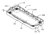
FIG. 1 is a perspective view of an insulative housing of an electrical connector assembly in accordance with the present invention;
FIG. 2 is a partially enlarged view of the insulative housing of FIG. 1;
FIG. 3 is a perspective view of a plurality of contacts of the electrical connector assembly with a carrier thereon in accordance with the present invention;
FIG. 4 is a perspective view of a pick-up cap in accordance with the present invention;
FIG. 5 is a view similar to FIG. 4, but taken from bottom and rear aspects;
FIG. 6 is a perspective view illustrating a plurality of contacts with carriers thereon being assembled to the pick-up cap, with solder balls on the contacts being illustrated by broken lines;
FIG. 7 is a view similar to FIG. 6, with the carriers being removed from the contacts and the solder balls on the contacts;
FIG. 8 is an assembled view of the electrical connector assembly in accordance with the present invention;
FIG. 9 is a partially cross-sectional view of the electrical connector assembly taken along line 9—9 of FIG. 8; and
FIG. 10 is a partially cross-sectional view of the insulative housing taken along line 10—10 of FIG. 1, with one contact being assembled therein and illustrated by broken lines.
Reference will now be made in detail to the preferred embodiment of the present invention.
Referring to FIGS. 8-10, an electrical connector assembly 1 in accordance with the present invention comprises an insulative housing 4, an array of contacts 2 assembled to the insulative housing 4, and a pick-up cap 3.
Referring to FIG. 1 and FIG. 2, the insulative housing 4 is of a substantially rectangular box shape and comprises a substantially planar base 40, a pair of longitudinal walls 42 and a pair of lateral walls 43 extending upwardly from periphery of the base 40. A first and a second polarizing tabs 430, 431 are respectively formed on the pair of opposite lateral walls 43 for properly mating with a complementary connector (not shown). A pair of recesses 420 is defined in each longitudinal wall 42. An array of passages 41 extend from a mating surface 400 toward a mounting surface 402 (referring to FIG. 9) of the base 40. A pair of opposite slots 412 is defined in a pair of opposite side surfaces 410 of the passage 41 and communicates with the passage 41. Thus, a step 414 (referring to FIG. 10) is formed in a middle of the passage 41.
Referring to FIG. 3, each contact 2 comprises a flat contacting portion 21, a connecting portion 23 opposite to the contacting portion 21, and a retention portion 22 connecting the contacting portion 21 and the connecting portion 23. The retention portion 22 has a smaller width than the contacting portion 21, thus, a pair of shoulders 210 is formed on a rear edge of the contacting portion 21. A plurality of barbs 220 is formed on opposite sides of the retention portion 22. The connecting portion 23 includes a solder pad 230 to have a fusible substrate contact mass or body, such as a solder ball 5 (referring to FIG. 7), attached thereon.
Referring to FIGS. 4-7, the pick-up cap 3 is a substantially rectangular plate and comprises a body portion 30. A first and a second engaging ears 320, 321 are respectively formed on opposite lateral sides 32 of the body portion 30. A pair of claws 310 is formed on each lengthwise side 31 perpendicular to the lateral sides 32. The body portion 30 comprises a smooth upper surface 34 and an opposite lower surface 33. A plurality of ribs 35 protrudes downwardly from the lower surface 33 of the body portion 30 and each has a slot 36 recessed therein.
Referring to FIGS. 6-10, in assembly, the contacts 2 with carriers 20 integrally formed therewith are assembled to the pick-up cap 3. Upper portions of the contacting portions 21 of the contacts 2 are respectively received in the slots 32 of the pick-up cap 3 and are gripped by the ribs 31. The carriers 20 are then cut away from the contacts 2 (referring to FIG. 7). The solder balls 5 are fused onto the solder pads 230 of the contacts 2. In an alternative embodiment, as shown in FIG. 5, the solder balls 5 can be fused onto the solder pads 230 before the carriers being cut away. The pick-up cap 3 with the contacts 2 are together preloaded to the insulative housing 4. At the time, the pick-up cap 3 with the contacts 2 are only placed on the housing 4. The shoulders 210 of the contacting portion 21 of each contact 2 abut against the steps 414 of a corresponding passage 41. The pick-up cap 3 is then pushed down toward the mounting surface 402 of the insulative housing 4 until the solder pads 230 are substantially coplanar with the mounting surface 402 (referring to FIG. 10). The shoulders 210 of the contacts 2 fit into the inner surfaces 410 of the passages 41. The first and the second engaging ears 320, 321 respectively engage with the first and the second polarizing tabs 430, 431. The claws 310 are respectively received in the recesses 420. Thus, the cap 3 engages with the insulative housing 4 reliably. A vacuum suction apparatus (not shown) engages, the pick-up cap 3 of the electrical connector assembly 1, and via suctioning the pick-up cap 3, places the electrical connector assembly 1 onto selected positions of a printed circuit board (not shown). The cap 3 will not be removed away from the insulative housing 4 until the contacts 2 are soldered to the printed circuit board.
The pick-up cap 3 in accordance with the present invention not only realizes its original function, but also functions as assembling the contacts 2 to the housing 4 instead of an additional tool. Thus, production efficiency is improved and manufacturing cost is decreased. In addition, the contacts 2 are secured by the pick-up cap 3 during being soldered to the printed circuit board, the contacts 2 have no possibility of moving between the insulative housing 4 and the cap 3. This assures the reliable electrical connection between the contacts 2 and the printed circuit board. It is understood that because the pick-up cap 3 reliably holds the contacts 2 in position on the printed circuit board during soldering, the contacts 2 and the housing 4 may be arranged in either the relatively fixing manner or the relatively floating manner without jeopardizing soldering.
It is to be understood, however, that even though numerous characteristics and advantages of the present invention have been set forth in the foregoing description, together with details of the structure and function of the invention, the disclosure is illustrative only, and changes may be made in detail, especially in matters of shape, size, and arrangement of parts within the principles of the invention to the full extent indicated by the broad general meaning of the terms in which the appended claims are expressed.
Claims (16)
1. An electrical connector assembly mountable on a printed circuit board, comprising:
an insulative housing;
a plurality of contacts received in the insulative housing, each contact comprising a contacting portion and a connecting portion adapted for being soldered to the printed circuit board; and
a pick-up cap removably assembled to the insulative housing and retaining and positioning the contacts in the insulative housing; wherein
the pick-up cap comprises a plurality of slots defined therein, and wherein the contacting portions of the contacts are received in the slots; wherein
the pick-up cap comprises an upper surface and an opposite lower surface, the pick-up cap comprises a plurality of ribs formed on the lower surface, and wherein the slots are recessed in the ribs.
2. The electrical connector assembly as claimed in claim 1 , wherein the contact comprises a retention portion connecting the contacting portion and the connecting portion thereof.
3. The electrical connector assembly as claimed in claim 2 , wherein the connecting portion of the contact forms a solder pad to retain a solder ball.
4. The electrical connector assembly as claimed in claim 2 , wherein the insulative housing comprises a mating surface and an opposite mounting surface, the housing defines a plurality of passages extending from the mating surface toward the mounting surface, and wherein the contacts are respectively received in the passages.
5. The electrical connector assembly as claimed in claim 2 , wherein each passage of the insulative housing comprises a pair of opposite slots defined therein to form a pair of steps in a middle thereof, and wherein each contact comprises a pair of shoulders formed on the contacting portion thereof and engaged with the steps of the passage.
6. The electrical connector assembly as claimed in claim 3 , wherein the solder pads of the contacts are substantially coplanar with the mounting surface of the insulative housing.
7. The electrical connector assembly as claimed in claim 1 , wherein the insulative housing comprises a polarizing tab, and wherein the cap has an engaging ear engaging with the polarizing tab of the housing.
8. The electrical connector assembly as claimed in claim 7 , wherein the insulative housing comprises a planar base and a periphery wall extending vertically from periphery of the base, and wherein the passages are defined in the base.
9. The electrical connector assembly as claimed in claim 8 , wherein the periphery wall comprises a pair of longitudinal walls and a pair of lateral walls, and wherein the polarizing tab is formed on the lateral wall.
10. The electrical connector assembly as claimed in claim 9 , wherein the pick-up cap is of a rectangular plate comprising a pair of lengthwise sides and a pair of lateral sides, each lengthwise side forms a claw thereof, and wherein each longitudinal wall defines a recess therein to receive the claw.
11. A method of assembling an electrical connector assembly, comprising the steps of:
providing an insulative housing comprising a mounting surface;
providing a pick-up cap;
providing a contact;
assembling the contact to the pick-up cap; and
assembling the pick-up cap with the contact to the insulative housing; wherein
the step of providing the pick-up cap comprises defining a slot therein, and wherein the contact comprises a contacting portion received in the slot and a connecting portion opposite to the contacting portion.
12. The method of assembling an electrical connector assembly as claimed in claim 11 , wherein the step of providing the pick-up cap comprises forming a rib thereon, and wherein the slot is recessed in the rib.
13. The method of assembling an electrical connector assembly as claimed in claim 11 , further comprising a step of fusing a solder ball onto the connecting portion of the contact before the step of preloading the pick-up cap with the contact to the insulative housing.
14. The method of assembling an electrical connector assembly as claimed in claim 11 , further comprising a step of fusing a solder ball onto the connecting portion of the contact after the step of pressing the pick-up cap toward the mounting surface of the insulative housing.
15. The method of assembling an electrical connector assembly as claimed in claim 11 , wherein the step of assembling the pick-up cap with the contact to the insulative housing comprises preloading the pick-up cap with the contact to the insulative housing and pressing the pick-up cap toward the mounting surface of the insulative housing until an end of the connecting portion of the contact is coplanar with the mounting surface of the insulative housing.
16. An electrical connector assembly comprising:
a printed circuit board;
an insulative housing located above the printed circuit board and defining a plurality of vertical passageways;
a pick-up cap detachably attached to a top portion of the housing and providing thereon an upward flat suction face facing away from the; and
a plurality of contacts disposed in the corresponding passageways, respectively, each of said contacts including opposite upper and lower portions; wherein
the pick-up cap reliably holds the upper portions of the contacts before and during soldering the lower portions of the contacts to the printed circuit board, and successively is removed from the housing, under a condition that the upper portions of the contacts are configured to prevent upward movement of the housing relative to the contacts after said pick-up cap is removed.
Priority Applications (5)
| Application Number | Priority Date | Filing Date | Title |
|---|---|---|---|
| US10/604,353 US6830457B1 (en) | 2003-07-14 | 2003-07-14 | Multi-function pick-up cap for electrical connector |
| CN03280589.6U CN2667695Y (en) | 2003-07-14 | 2003-09-19 | Electric connector |
| TW092126287A TWI239693B (en) | 2003-07-14 | 2003-09-24 | Multi-function pick-up cap for electrical connector |
| CN200310101910.0A CN100521406C (en) | 2003-07-14 | 2003-10-11 | Assembling method for electrical connector |
| US10/840,989 US20050009385A1 (en) | 2003-06-23 | 2004-05-07 | Electrical connector having improved contacts |
Applications Claiming Priority (1)
| Application Number | Priority Date | Filing Date | Title |
|---|---|---|---|
| US10/604,353 US6830457B1 (en) | 2003-07-14 | 2003-07-14 | Multi-function pick-up cap for electrical connector |
Related Child Applications (1)
| Application Number | Title | Priority Date | Filing Date |
|---|---|---|---|
| US10/840,989 Continuation-In-Part US20050009385A1 (en) | 2003-06-23 | 2004-05-07 | Electrical connector having improved contacts |
Publications (1)
| Publication Number | Publication Date |
|---|---|
| US6830457B1 true US6830457B1 (en) | 2004-12-14 |
Family
ID=33490822
Family Applications (1)
| Application Number | Title | Priority Date | Filing Date |
|---|---|---|---|
| US10/604,353 Expired - Fee Related US6830457B1 (en) | 2003-06-23 | 2003-07-14 | Multi-function pick-up cap for electrical connector |
Country Status (3)
| Country | Link |
|---|---|
| US (1) | US6830457B1 (en) |
| CN (2) | CN2667695Y (en) |
| TW (1) | TWI239693B (en) |
Cited By (8)
| Publication number | Priority date | Publication date | Assignee | Title |
|---|---|---|---|---|
| US20060046526A1 (en) * | 2004-08-31 | 2006-03-02 | Minich Steven E | Contact protector for electrical connectors |
| US20060181364A1 (en) * | 2005-02-17 | 2006-08-17 | Hall David R | Apparatus for Reducing Noise |
| US7097465B1 (en) * | 2005-10-14 | 2006-08-29 | Hon Hai Precision Ind. Co., Ltd. | High density connector with enhanced structure |
| US20060218784A1 (en) * | 2005-04-05 | 2006-10-05 | Minich Steven E | Pickup cap for an electrical connector |
| US20080153330A1 (en) * | 2006-09-29 | 2008-06-26 | Fci Americas Technology, Inc. | Pickup caps for electrical connectors |
| US20110177702A1 (en) * | 2010-01-19 | 2011-07-21 | Hon Hai Precision Industry Co., Ltd. | Electrical connector with removable housing |
| CN104112932A (en) * | 2013-04-22 | 2014-10-22 | 康而富控股股份有限公司 | Electrical connector |
| US20140357129A1 (en) * | 2013-05-30 | 2014-12-04 | Concraft Holding Co., Ltd. | Electrical connector |
Families Citing this family (2)
| Publication number | Priority date | Publication date | Assignee | Title |
|---|---|---|---|---|
| CN109149177B (en) * | 2018-08-08 | 2022-09-20 | 富顶精密组件(深圳)有限公司 | Method for manufacturing electric connector |
| CN109904659B (en) * | 2019-03-19 | 2020-09-29 | 番禺得意精密电子工业有限公司 | Terminal combination and electric connector assembly |
Citations (14)
| Publication number | Priority date | Publication date | Assignee | Title |
|---|---|---|---|---|
| US4726793A (en) * | 1986-02-06 | 1988-02-23 | Amp Incorporated | Electrical socket, application tool and method for positioning electrical sockets on circuit boards for surface soldering |
| US5026295A (en) | 1990-07-31 | 1991-06-25 | Molex Incorporated | Cover for an electrical connector |
| US5342214A (en) * | 1993-11-01 | 1994-08-30 | Hsu Feng Chien | IC socket |
| US6042389A (en) | 1996-10-10 | 2000-03-28 | Berg Technology, Inc. | Low profile connector |
| US6116949A (en) | 1999-01-13 | 2000-09-12 | The Whitaker Corporation | Electrostatic protection cover for electrical connector |
| US6164983A (en) * | 1996-10-10 | 2000-12-26 | Berg Technology, Inc. | High density connector |
| US6231367B1 (en) * | 1998-12-31 | 2001-05-15 | Hon Hai Precision Ind. Co., Ltd. | Method for achieving substantially uniform expansion of dielectric plate and electrical connector made in accordance therewith |
| US6241535B1 (en) | 1996-10-10 | 2001-06-05 | Berg Technology, Inc. | Low profile connector |
| US6371776B1 (en) | 2000-11-10 | 2002-04-16 | Hon Hai Precision Ind. Co., Ltd. | Electrical connector with vacuum placement cover |
| US6439901B1 (en) | 2001-10-11 | 2002-08-27 | Hon Hai Precoision Ind. Co., Ltd. | Electrical connector with releasable pick-up device |
| US6478588B1 (en) * | 2001-12-28 | 2002-11-12 | Hon Hai Precision Ind. Co., Ltd. | CPU socket assembly with pick up cap |
| US6506064B1 (en) | 2001-12-20 | 2003-01-14 | Hon Hai Precision Ind. Co., Ltd. | Pick-and-place cap for connector having bail latches |
| US6554624B1 (en) * | 2001-12-06 | 2003-04-29 | Hon Hai Precision Ind. Co., Ltd. | Socket assembly with pick-up cap |
| US6699048B2 (en) * | 2002-01-14 | 2004-03-02 | Fci Americas Technology, Inc. | High density connector |
-
2003
- 2003-07-14 US US10/604,353 patent/US6830457B1/en not_active Expired - Fee Related
- 2003-09-19 CN CN03280589.6U patent/CN2667695Y/en not_active Expired - Fee Related
- 2003-09-24 TW TW092126287A patent/TWI239693B/en not_active IP Right Cessation
- 2003-10-11 CN CN200310101910.0A patent/CN100521406C/en not_active Expired - Fee Related
Patent Citations (14)
| Publication number | Priority date | Publication date | Assignee | Title |
|---|---|---|---|---|
| US4726793A (en) * | 1986-02-06 | 1988-02-23 | Amp Incorporated | Electrical socket, application tool and method for positioning electrical sockets on circuit boards for surface soldering |
| US5026295A (en) | 1990-07-31 | 1991-06-25 | Molex Incorporated | Cover for an electrical connector |
| US5342214A (en) * | 1993-11-01 | 1994-08-30 | Hsu Feng Chien | IC socket |
| US6042389A (en) | 1996-10-10 | 2000-03-28 | Berg Technology, Inc. | Low profile connector |
| US6241535B1 (en) | 1996-10-10 | 2001-06-05 | Berg Technology, Inc. | Low profile connector |
| US6164983A (en) * | 1996-10-10 | 2000-12-26 | Berg Technology, Inc. | High density connector |
| US6231367B1 (en) * | 1998-12-31 | 2001-05-15 | Hon Hai Precision Ind. Co., Ltd. | Method for achieving substantially uniform expansion of dielectric plate and electrical connector made in accordance therewith |
| US6116949A (en) | 1999-01-13 | 2000-09-12 | The Whitaker Corporation | Electrostatic protection cover for electrical connector |
| US6371776B1 (en) | 2000-11-10 | 2002-04-16 | Hon Hai Precision Ind. Co., Ltd. | Electrical connector with vacuum placement cover |
| US6439901B1 (en) | 2001-10-11 | 2002-08-27 | Hon Hai Precoision Ind. Co., Ltd. | Electrical connector with releasable pick-up device |
| US6554624B1 (en) * | 2001-12-06 | 2003-04-29 | Hon Hai Precision Ind. Co., Ltd. | Socket assembly with pick-up cap |
| US6506064B1 (en) | 2001-12-20 | 2003-01-14 | Hon Hai Precision Ind. Co., Ltd. | Pick-and-place cap for connector having bail latches |
| US6478588B1 (en) * | 2001-12-28 | 2002-11-12 | Hon Hai Precision Ind. Co., Ltd. | CPU socket assembly with pick up cap |
| US6699048B2 (en) * | 2002-01-14 | 2004-03-02 | Fci Americas Technology, Inc. | High density connector |
Cited By (14)
| Publication number | Priority date | Publication date | Assignee | Title |
|---|---|---|---|---|
| US7278856B2 (en) | 2004-08-31 | 2007-10-09 | Fci Americas Technology, Inc. | Contact protector for electrical connectors |
| US20060046526A1 (en) * | 2004-08-31 | 2006-03-02 | Minich Steven E | Contact protector for electrical connectors |
| US20060181364A1 (en) * | 2005-02-17 | 2006-08-17 | Hall David R | Apparatus for Reducing Noise |
| US7445453B2 (en) | 2005-04-05 | 2008-11-04 | Fci Americas Technology, Inc. | Pickup cap for an electrical connector |
| US20060218784A1 (en) * | 2005-04-05 | 2006-10-05 | Minich Steven E | Pickup cap for an electrical connector |
| US7097465B1 (en) * | 2005-10-14 | 2006-08-29 | Hon Hai Precision Ind. Co., Ltd. | High density connector with enhanced structure |
| US20080153330A1 (en) * | 2006-09-29 | 2008-06-26 | Fci Americas Technology, Inc. | Pickup caps for electrical connectors |
| US7621751B2 (en) | 2006-09-29 | 2009-11-24 | Fci Americas Technology, Inc. | Pickup caps for electrical connectors |
| US20110177702A1 (en) * | 2010-01-19 | 2011-07-21 | Hon Hai Precision Industry Co., Ltd. | Electrical connector with removable housing |
| US8100698B2 (en) * | 2010-01-19 | 2012-01-24 | Hon Hai Precision Ind. Co., Ltd. | Electrical connector with removable housing |
| CN104112932A (en) * | 2013-04-22 | 2014-10-22 | 康而富控股股份有限公司 | Electrical connector |
| CN104112932B (en) * | 2013-04-22 | 2016-08-17 | 康而富控股股份有限公司 | Electric connector |
| US20140357129A1 (en) * | 2013-05-30 | 2014-12-04 | Concraft Holding Co., Ltd. | Electrical connector |
| US8961233B2 (en) * | 2013-05-30 | 2015-02-24 | Concraft Holding Co., Ltd. | Electrical connector |
Also Published As
| Publication number | Publication date |
|---|---|
| TWI239693B (en) | 2005-09-11 |
| CN100521406C (en) | 2009-07-29 |
| CN2667695Y (en) | 2004-12-29 |
| TW200503342A (en) | 2005-01-16 |
| CN1578019A (en) | 2005-02-09 |
Similar Documents
| Publication | Publication Date | Title |
|---|---|---|
| JP3477640B2 (en) | connector | |
| US7179126B2 (en) | Electrical connector with improved terminals | |
| US6964573B2 (en) | Electronic part-mounting socket | |
| US6155848A (en) | Auxiliary device for ZIF electrical connector | |
| US6764336B2 (en) | Method for forming an electrical connector and an electrical connector obtained thereby | |
| US7255600B2 (en) | Module assembly and equipment for fitting the same | |
| US20030228809A1 (en) | Terminals for an electrical socket | |
| US6368156B1 (en) | Audio jack conveniently and reliably mounted on a circuit board | |
| US6626691B2 (en) | Pick up cap for BGA socket | |
| US6957987B2 (en) | Socket connector for integrated circuit | |
| US6830457B1 (en) | Multi-function pick-up cap for electrical connector | |
| US20050037642A1 (en) | Electrical connector | |
| US7090546B2 (en) | Card connector | |
| US6186816B1 (en) | Electrical connector | |
| US6554634B1 (en) | Electrical contact for ZIF socket connector | |
| US20030232517A1 (en) | Electrical connector assembly | |
| US6454615B1 (en) | High-speed electrical connector | |
| US20030232529A1 (en) | Electrical connector with terminal insertion guide mechanisms | |
| US6471535B1 (en) | Electrical socket | |
| US7118392B2 (en) | Electrical connector and method for manufacturing same | |
| US6210177B1 (en) | Electrical connector | |
| US20070218722A1 (en) | Electrical connector assembly | |
| US7097517B2 (en) | Socket connector for integrated circuit | |
| US6416337B1 (en) | Connector assembly | |
| US6371803B1 (en) | Electrical connector having boardlock for securing the electrical connector to a printed circuit board |
Legal Events
| Date | Code | Title | Description |
|---|---|---|---|
| AS | Assignment |
Owner name: HON HAI PRECISION IND. CO., LTD., TAIWAN Free format text: ASSIGNMENT OF ASSIGNORS INTEREST;ASSIGNORS:KORSUNSKY, IOSIF R;GILLESPIE, BRIAN J;WALKER, KEVIN E;REEL/FRAME:013796/0068 Effective date: 20030703 |
|
| FPAY | Fee payment |
Year of fee payment: 4 |
|
| REMI | Maintenance fee reminder mailed | ||
| LAPS | Lapse for failure to pay maintenance fees | ||
| STCH | Information on status: patent discontinuation |
Free format text: PATENT EXPIRED DUE TO NONPAYMENT OF MAINTENANCE FEES UNDER 37 CFR 1.362 |
|
| FP | Lapsed due to failure to pay maintenance fee |
Effective date: 20121214 |