US6840561B2 - Sun visor and cover attachment method - Google Patents

Sun visor and cover attachment method Download PDF

Info

Publication number
US6840561B2
US6840561B2 US10/262,682 US26268202A US6840561B2 US 6840561 B2 US6840561 B2 US 6840561B2 US 26268202 A US26268202 A US 26268202A US 6840561 B2 US6840561 B2 US 6840561B2
Authority
US
United States
Prior art keywords
core halves
core
sun visor
cover
halves
Prior art date
Legal status (The legal status is an assumption and is not a legal conclusion. Google has not performed a legal analysis and makes no representation as to the accuracy of the status listed.)
Expired - Fee Related
Application number
US10/262,682
Other versions
US20040066056A1 (en
Inventor
Donald Mills
Jay Burgess
Current Assignee (The listed assignees may be inaccurate. Google has not performed a legal analysis and makes no representation or warranty as to the accuracy of the list.)
Grupo Antolin Ingenieria SA
Original Assignee
Grupo Antolin Ingenieria SA
Priority date (The priority date is an assumption and is not a legal conclusion. Google has not performed a legal analysis and makes no representation as to the accuracy of the date listed.)
Filing date
Publication date
Family has litigation
First worldwide family litigation filed litigation Critical https://patents.darts-ip.com/?family=32041863&utm_source=google_patent&utm_medium=platform_link&utm_campaign=public_patent_search&patent=US6840561(B2) "Global patent litigation dataset” by Darts-ip is licensed under a Creative Commons Attribution 4.0 International License.
Application filed by Grupo Antolin Ingenieria SA filed Critical Grupo Antolin Ingenieria SA
Priority to US10/262,682 priority Critical patent/US6840561B2/en
Assigned to GRUPO ANTOLIN INGENIERIA, S.A. reassignment GRUPO ANTOLIN INGENIERIA, S.A. ASSIGNMENT OF ASSIGNORS INTEREST (SEE DOCUMENT FOR DETAILS). Assignors: MILLS, DONALD
Priority to ES03759631T priority patent/ES2304528T3/en
Priority to EP03759631A priority patent/EP1575794B1/en
Priority to AU2003275355A priority patent/AU2003275355A1/en
Priority to MXPA05003375A priority patent/MXPA05003375A/en
Priority to DE60320022T priority patent/DE60320022T2/en
Priority to CN200380104779.1A priority patent/CN1738729A/en
Priority to AT03759631T priority patent/ATE390310T1/en
Priority to PCT/US2003/031069 priority patent/WO2004030964A1/en
Publication of US20040066056A1 publication Critical patent/US20040066056A1/en
Publication of US6840561B2 publication Critical patent/US6840561B2/en
Application granted granted Critical
Anticipated expiration legal-status Critical
Expired - Fee Related legal-status Critical Current

Links

Images

Classifications

    • BPERFORMING OPERATIONS; TRANSPORTING
    • B60VEHICLES IN GENERAL
    • B60JWINDOWS, WINDSCREENS, NON-FIXED ROOFS, DOORS, OR SIMILAR DEVICES FOR VEHICLES; REMOVABLE EXTERNAL PROTECTIVE COVERINGS SPECIALLY ADAPTED FOR VEHICLES
    • B60J3/00Antiglare equipment associated with windows or windscreens; Sun visors for vehicles
    • B60J3/02Antiglare equipment associated with windows or windscreens; Sun visors for vehicles adjustable in position
    • B60J3/0204Sun visors
    • B60J3/0278Sun visors structure of the body

Definitions

  • the present invention relates, in general, to vehicle sun visors.
  • Sun visors are used in vehicles to provide front and side window protection from sunlight entry. Such sun visors are pivotal about a longitudinal axis between a stowed position adjacent the headliner and a deployed position angularly extending from the headliner. Most sun visors can also be unlocked from a headliner mounted clip or D-ring and pivoted to the side window about a support arm attached to the vehicle headliner. A biasing means is typically mounted within the visor to prevent movement and noise when the sun visor is in the stowed position.
  • sun visors Over the years, various enhancements or features have been added for sun visors to increase their versatility as well as to add other convenience factors to the vehicle occupants.
  • One such feature is the telescopic extension of the entire sun visor along the longitudinal axis of the support arm to enable the sun visor to be repositioned laterally across the windshield or the side window to block sun light entry in a particular direction for an occupant.
  • Another common feature is a mirror with or without a pivotal cover and with or without an illumination means which is mounted in one surface of the sun visor, typically the surface facing the headliner when the sun visor is in the stowed position.
  • the sun visor need only be pivoted to the angular downward extending position to allow use of the mirror.
  • an illumination means such as lamps
  • electrical conductors or wires extend through the A pillar of the vehicle body and the support arm to the individual lamps in the sun visor.
  • mount fabric or decorative covers over the plastic sun visor core.
  • One such mount traps the ends of the fabric cover between the two clam shell core halves when the halves are moved to their closed, locked position.
  • Another mount utilizes projections on the inner surfaces of the core halves over which the inner edges of the fabric cover are forced.
  • Heat stake projections have also been provided about the periphery of the core halves.
  • the edges of the fabric cover are forced over the heat stake projections and then heat is applied to melt the stakes through the interstices of the fabric cover to fixedly retain the inner edges of the cover in a fixed position on the sun visor core.
  • the present invention is a sun visor having a unique decorative or outer fabric cover attachment structure and method.
  • the inventive method includes the steps of forming a core with first and second core halves oppositely extending from a common hinge edge.
  • the method also includes forming a receiving surface on each of the first and second core halves spaced from a periphery of the first and second core halves.
  • the method further includes the step of overlaying the core over a cover with the edge portions of the cover folded over the peripheral edges of the first and second core halves into engagement with the receiving surfaces on the first and second core halves. Finally, the edges of the cover are joined to the receiving surfaces.
  • the method further includes the step of forming the receiving surface on at least one of the first and second core halves in the form of a continuous surface.
  • the continuous surface in one aspect, has a planar end.
  • the receiving surfaces in the first and second core halves are positioned to overlay each other when the first and second core halves are moved to the closed, assembled position.
  • the present invention also defines a sun visor including a core with the first and second foldable core halves, and a receiving surface on each of the first and second core halves spaced from a periphery of each of the first and second core halves.
  • a cover has edges folded over the periphery of the first and second core halves and heat joined to the receiving surfaces on the first and second core halves.
  • the receiving surface in each of the first and second halves defines a continuous surface between opposed ends.
  • the receiving surface defines a planar end raised from the plane of a major portion of each of the first and second core halves.
  • the receiving surfaces in the first and second core halves overlay each other in alignment when the first and second core halves are folded together into a closed, assembled position.
  • the cover attachment structure and method of the present invention provides a secure cover attachment to a sun visor core over a substantially continuous portion of the peripheral edges of the two core halves. This insures a more secure and smoother attachment of the cover to the core as compared to the typical prior art use of spaced projections or spikes in the core halves over which the fabric cover is forcibly urged and then heat welded together.
  • FIG. 1 is a perspective view of a completely assembled sun visor according to one aspect of the present invention
  • FIG. 2 is an elevational view of an open clam shell core for the sun visor shown in FIG. 1 , depicting the initial step of attaching the fabric cover to the core;
  • FIG. 3 is an enlarged, cross-sectional view of one corner of the clam shell core in the closed position showing the edge fold and edge material attached to the core;
  • FIG. 4 is an enlarged, perspective view of the corner of the core shown in FIG. 3 ;
  • FIG. 5 is an exploded, perspective view of the slide carrier, clip and large support rod according to one aspect of the present invention
  • FIG. 6 is a cross sectional view showing the slider carrier, clip and support rod in a closed core position
  • FIG. 7 is a perspective view of the sun visor of FIG. 1 depicting the slider means in the normal, retracted position;
  • FIG. 8 is a perspective view similar to FIG. 7 , but showing the slide carrier in the fully extended sun visor position;
  • FIG. 9 is a perspective view of the sun visor of FIG. 1 having a short length, non-telescoping support arm;
  • FIG. 10 is a perspective view of another aspect of the sun visor according to the present invention shown in an open core position and depicting the mounting of a mirror to one core half;
  • FIG. 11 is a perspective view of a completed sun visor showing one aspect of a fully optioned mirror assembly with a cover deployed in a closed position;
  • FIG. 13 is a cross-sectional view through the sun visor of FIG. 11 depicting the mounting of the mirror assembly to the core and cover;
  • FIG. 14 is a perspective view of another aspect of a sun visor according to the present invention having a mirror assembly mounted therein;
  • FIG. 15 is a cross-sectional view of an alternate aspect of the sun visor of the present invention.
  • a sun visor denoted generally by reference number 10 which includes a number of features, all described hereafter, which may be used in various combinations as well as individually, separate from the other features.
  • the sun visor 10 includes a core 12 , a cover 14 typically made of fabric, including synthetics and natural fabrics, a support arm formed of either a long length support arm 16 allowing telescoping movement of the sun visor 10 as described hereafter and as shown in FIGS. 7 and 8 or a short length support arm 18 shown in FIG. 9 which does not provide telescoping extension of the sun visor 10 .
  • the sun visor 10 may also include a mirror assembly shown in various feature combinations in FIGS. 11-14 .
  • the core 12 is in the form of a clam shell having a first clam shell portion or half 20 and a second portion or half 22 .
  • the core 12 is formed of a suitable, light weight, easily formed material, such as plastic.
  • a plastic useable to form the core 12 maybe polypropylene, by example only.
  • the core halves 20 and 22 have a substantially mirror image configuration formed of opposed longitudinal edges joined together to form the living hinge 24 , outer longitudinal edges 26 and 28 , adjacent side edges 30 and 32 , and adjacent side edges 34 and 36 .
  • the side edges 26 and 28 may optionally be formed as part of a pivotal flap section pivotable about a second living hinge or weakened portion 38 formed adjacent from each side edge 26 and 28 .
  • an intermediate portion between the side edges 30 and 32 and an intermediate portion 40 between the side edges 30 and 32 of the first and second core halves 20 and 22 , respectively, is recessed to form a space for insertion of one support arm 16 or 18 into the core 12 .
  • An end portion of the living hinge 24 between the core halves 20 and 22 is formed with an aperture 42 which, when the core 12 is in the closed, fully assembled position shown in FIG. 1 , defines an open ended recess adapted for receiving a D-ring 44 for securing one end of the sun visor 10 to a latch member mounted in a vehicle head liner, not shown.
  • the D-ring 44 is mounted in the core 12 by suitable clips, not shown.
  • the cover mounting means includes an elongated, elevated cover attachment surfaces 50 and 52 respectively formed in the core halves 20 and 22 .
  • Each surface 50 and 52 is formed as one elongated projection extending between the side edges 30 and 34 and the side edges 32 and 36 or in a discontinuous fashion formed of multiple segments or projections.
  • Each surface 50 and 52 terminates in a suitably formed outer mounting surface 54 and 56 , respectively.
  • Each surface 54 and 56 may be planar or have any other shape, such a smoothly curved concave or convex shape.
  • each surface 50 and 52 has a generally C-shape, formed as a continuous member projecting outward from the main extent or plane of the core halves 20 and 22 .
  • the core 12 and the cover 14 are juxtaposed as shown in FIG. 2 with cover 14 overlaying an outer surface of the core 12 .
  • the outer peripheral edge of the cover 14 shown by reference number 58 projects outward beyond the periphery of the side edges 30 , 32 , 34 and 36 of the core 12 .
  • the outer peripheral edge 58 of the cover 14 is then folded over a peripheral lip 60 and 62 on each core half 20 and 22 and inward to a position in which the peripheral edge 58 of the cover 14 is in contact with and overlays each of the surfaces 54 and 56 on the surfaces 50 and 52 .
  • Lock means are provided for securing locking the core halves 20 and 22 in a fully assembled, closed position shown in FIGS. 3 and 4 .
  • the lock means comprises a plurality of posts denoted generally by reference number 80 which are formed of a stem 82 and a head 84 having a radially outward extending periphery formed of at least two side arms 86 and 88 . Rather than just two side arms 86 and 88 , the entire periphery of the head 84 may be enlarged to a greater diameter or cross-section dimension than the diameter or cross-section of the stem 82 so as to provide an enlarged head which overhangs the outer periphery of the stem 82 as shown in FIG. 3 .
  • the posts 80 are deployed at a number of locations on one of the core halves 20 and 22 , with the post 80 being shown by way of example only as being mounted on the core half 22 .
  • a plurality of lock receivers 90 are formed in the other core half 20 .
  • the lock receivers 90 include an outer wall formed of at least two wall portions 92 and 94 , with additional wall portions, including a third wall portion and even a fourth wall portion to form walls 92 , 94 , 95 and 97 as a completely closed, continuous wall may also be employed.
  • Lock members are resiliently mounted on and extend from an end of at least two of the side walls 92 and 94 .
  • the lock members all denoted generally by reference number 96 include a leg 98 which terminates in an outer end 100 .
  • the legs 98 of the lock members 96 are disposed at an acute angle from the adjacent side wall 92 or 94 such that the outer end 100 is pivotal about the connection between the legs 98 and the adjacent side walls 92 and 94 of each receiver 90 .
  • This pivotal movement allows the head 84 of a complementarity positioned lock post 80 on the mating core half 22 to slide through the space normally existing between two adjacent lock legs 98 thereby urging the outer ends 100 outward until the head 84 snaps past the outer ends 100 of the legs 98 .
  • the legs 98 then snap back toward the nominal position and seat against a shoulder formed between the inner surface of the side arms 86 and 88 of the head 84 and the adjacent outer surface of the stem 82 thereby securely locking the lock post 80 in the receiver 90 .
  • the same locking process occurs across the entire core 12 at every location of a matingly positioned receiver 90 and lock post 80 .
  • the support arm 16 is mounted within the core 12 prior to locking closure of the core halves 20 and 22 as described above.
  • the support arm may take one of two configurations, including the telescoping, long length support arm 16 shown in FIGS. 7 and 8 and the shorter length support arm 18 shown in FIG. 9 for non-telescoping sun visors.
  • each support arm 16 or 18 includes at least one and preferably a pair of flats 110 adjacent an outer end 112 , with only the support arm 16 being depicted in FIG. 5 by way of example only.
  • the remainder of the support arm 16 may have a circular cross-section, by example only.
  • a stop flange 114 is spaced from the outer end 112 of the support arm 18 to retain the support arm 18 in a slide carrier 120 .
  • the carrier 120 defines an integral, one piece body, typically of a molded plastic, having a pair of side arms 122 and 124 , each with an aperture 126 and 128 , respectively, the apertures 126 and 128 being coaxially aligned for receiving the end portion of the support arm 18 with the flats 110 disposed between the side arms 122 and 124 .
  • a first pair of apertures 130 are formed in a central leg 132 of the slider 120 .
  • a second pair of apertures 134 are also formed in the central leg 132 of the slider 120 .
  • the pairs of apertures 130 and 134 receive bent edges 136 and 138 of a spring clip 140 to attach the spring clip 140 to the slider 120 .
  • the spring clip 140 has an enlarged end portion denoted by reference number 142 which receives the end portion of the support arm 16 .
  • a pair of bent portions 144 and 146 on the spring clip 140 resiliently engage the flats 110 on the end of the support arm 18 to exert a biasing force tending to retain the entire sun visor 10 in a fixed position, typically biased in a direction toward the vehicle headliner in a normal, stored sun visor position to minimize buzz, squeaks or rattles. This provides the necessary noise control features for the sun visor 10 of the present invention.
  • the sun visor 10 has a unique telescoping mount using the slide carrier 120 which may be used by itself or in combination with the heat stake cover attachment described above as well as with or without any of the additional unit features of the sun visor described hereafter.
  • the slide carrier 120 includes first and second, oppositely directed, open ended channels 150 and 152 which are integrally formed in the carrier 120 .
  • the open end of the channel 150 extends oppositely from the open end of the channel 152 .
  • the channels 150 and 152 are positioned to engage slide rails 154 and 156 , shown in FIGS. 2 , 6 , 7 and 8 which are integrally formed as part of the core halves 20 and 22 , respectively.
  • the slide rails 154 and 156 extend along the length of each core half 20 and 22 , generally in parallel with the hinge 24 .
  • the slide rail 154 engages the channel 150 and the opposed slide rail 156 engages the opposite channel 152 in the slider 120 .
  • This dual, opposed slide rail and channel configuration securely retains the slider 120 in a constant orientation during all telescoping movement of the sun visor 10 relative to the support arm 16 as described hereafter.
  • the addition of the second channel 150 and the slide rail 154 provides added stability to insure a smooth, even bi-directional telescoping movement of the sun visor 10 along the support arm 16 while at the same time securely retaining the sun visor 10 to the support arm 16 .
  • FIG. 7 depicts the normal, non-telescope position of the sun visor 10 relative to the support arm 16 .
  • the carrier 120 is disposed adjacent to the D-ring end of the sun visor 10 .
  • the occupant grasps the sun visor 10 and slides the sun visor 10 along the support arm 16 to any position up to a maximum extend position shown in FIG. 8 .
  • the carrier 120 is disposed adjacent to a support arm pivot support or clip 160 .
  • the clip 160 shown in FIGS.
  • 7 , 8 and 9 includes a wall integrally formed on one of the core halves, such as the second core half 22 having an aperture 162 for receiving the support arm 16 therethrough.
  • the portion 164 of the wall 160 carrying the aperture 162 is spaced from a collar 166 , also formed on the core half 22 , which defines a generally circular cross-section bore through which the support arm 16 extends.
  • the sun visor 10 may also be provided with the short length support arm 18 for non-telescoping use without any modifications to the core 12 .
  • the non-telescoping aspect of the present sun visor 10 also employs the carrier 120 , the support wall 160 and the sleeve 166 .
  • the carrier 120 is non-laterally moveably disposed within the wall 160 as shown in FIG. 9 .
  • At least one and preferably a plurality of spaced apertures 174 are formed in the wall 172 .
  • Each aperture 174 is alignable with a corresponding lock receiver 90 on the mating core half 20 .
  • Each aperture 174 is positioned to receive a lock post 80 , identical to the lock post 80 described above for locking the core halves 20 and 22 in the fully closed, assembled position, but now provided on a back plate 176 of a frame or mirror support.
  • the lock posts 80 project from the back wall or plate 176 so as to extend through the apertures 174 and the wall 172 and into locking engagement with the mating receiver 90 when the core halves 20 and 22 are pivoted to the fully closed position. This enables the mirror assembly to be fixedly attached to the core 10 at the same time the core halves 20 and 22 are locked in the closed, fully assembled position.
  • FIGS. 11 and 12 depict an opposite surface of the core half 22 which has the recess 170 formed therein for receiving a mirror assembly 182 .
  • the mirror assembly 182 includes a moveable or pivotal cover 184 which is pivotally mounted to a frame 186 formed of a fixed frame member 188 attached to the back plate 176 shown in FIG. 10 and a mirror surround frame 190 , only a portion of which is shown in FIG. 11 .
  • the cover 184 has a generally planar extent, with depending side walls and a raised edge 192 to permit easy pivotal movement of the cover 184 between open and closed positions shown in FIGS. 12 and 11 , respectively.
  • a hinge 189 is provided between a fixed frame element 188 and the cover 184 .
  • the mirror assembly 182 also is provided with an illumination means in the form of one or more lamp means 196 and 198 mounted in the mirror surround frame 190 on at least one and preferably opposed sides of a reflective mirror 200 .
  • the mirror 200 is typically adhesively joined to the back plate 176 .
  • Conductors for conducting power to the light means 196 and 198 located below the bezzles or lenses 202 are routed between the closed core halves 20 and 22 and into an aperture formed in the support arm 16 or 18 whereby the wires exit the sun visor 10 and pass through the vehicle interior, typically through the vehicle A pillar to the accessory power vehicle circuit.
  • the mirror assembly 182 is mounted on the sun visor 10 after the core halves 20 and 22 of the sun visor 10 have been pivoted to the closed, latched position.
  • the lock post 80 may be forced through the fabric cover 14 into the underlying receiver 90 to fixedly mount the mirror assembly 182 to the sun visor 10 .
  • the layer of the cover fabric 14 disposed between the back wall 176 of the mirror assembly 182 and the core half 20 minimizes the generation of buzzes, squeaks and rattles.
  • the core 10 having the recess 172 formed in one of the core halves for receiving one of the mirror assemblies described above may also be utilized without any mirror assemble.
  • a filler member 220 has a peripheral shape complementary to the shape of the recess 170 in the core half 22 and a thickness substantially the same as the depth of the recess 170 .
  • the filler member 220 is mounted within the recess 170 and covered by the cover 14 which holds the filler member 220 in the recess 170 .
  • the filler member 220 may be fixed in the recess 170 by means of adhesive, etc.
  • the filler member 220 provides a flush surface with the surrounding surface of the core half 22 when a mirror assembly is not used in the sun visor 10 .
  • the filler member enables a single core 12 design to be employed with and without a mirror assembly without requiring any modification or additional manufacturing cost.
  • a unique vehicle sun visor having improved fabric cover attachment, easy and reliable telescoping visor movement, the option to switch between a telescoping support arm and a fixed short support arm without modification to the sun visor core so as to contribute to a reduced manufacturing cost, multiple mirror assembly mounts, unique and reliable core lock members, and a mirror attachment means which controls or minimizes the generation of noise between the contacting parts of the mirror and the sun visor core.

Abstract

The sun visor has a decorative cover securely affixed over a core formed of foldable first and second core halves. Receiving surfaces defining a planar end are formed on each of the first and second core halves and extend substantially continuously between opposed ends. The edges of the cover are folded over onto the receiving surfaces and fixed to the receiving surfaces

Description

BACKGROUND
The present invention relates, in general, to vehicle sun visors.
Sun visors are used in vehicles to provide front and side window protection from sunlight entry. Such sun visors are pivotal about a longitudinal axis between a stowed position adjacent the headliner and a deployed position angularly extending from the headliner. Most sun visors can also be unlocked from a headliner mounted clip or D-ring and pivoted to the side window about a support arm attached to the vehicle headliner. A biasing means is typically mounted within the visor to prevent movement and noise when the sun visor is in the stowed position.
Over the years, various enhancements or features have been added for sun visors to increase their versatility as well as to add other convenience factors to the vehicle occupants.
One such feature is the telescopic extension of the entire sun visor along the longitudinal axis of the support arm to enable the sun visor to be repositioned laterally across the windshield or the side window to block sun light entry in a particular direction for an occupant.
Another common feature is a mirror with or without a pivotal cover and with or without an illumination means which is mounted in one surface of the sun visor, typically the surface facing the headliner when the sun visor is in the stowed position. The sun visor need only be pivoted to the angular downward extending position to allow use of the mirror.
When an illumination means, such as lamps, are provided around the mirror, electrical conductors or wires extend through the A pillar of the vehicle body and the support arm to the individual lamps in the sun visor.
Various means have been provided to mount fabric or decorative covers over the plastic sun visor core. One such mount traps the ends of the fabric cover between the two clam shell core halves when the halves are moved to their closed, locked position. Another mount utilizes projections on the inner surfaces of the core halves over which the inner edges of the fabric cover are forced.
Heat stake projections have also been provided about the periphery of the core halves. In this mounting technique, the edges of the fabric cover are forced over the heat stake projections and then heat is applied to melt the stakes through the interstices of the fabric cover to fixedly retain the inner edges of the cover in a fixed position on the sun visor core.
Despite the improvements which have been made to vehicle sun visors, it would still be desirable to provide an improved sun visor which is easier to manufacture, have a more pleasing exterior aesthetic appearance, can be manufactured at a lower cost, and has improved buzz, squeak and rattle control features.
SUMMARY
The present invention is a sun visor having a unique decorative or outer fabric cover attachment structure and method.
In one aspect, the inventive method includes the steps of forming a core with first and second core halves oppositely extending from a common hinge edge. The method also includes forming a receiving surface on each of the first and second core halves spaced from a periphery of the first and second core halves. The method further includes the step of overlaying the core over a cover with the edge portions of the cover folded over the peripheral edges of the first and second core halves into engagement with the receiving surfaces on the first and second core halves. Finally, the edges of the cover are joined to the receiving surfaces.
In another aspect, the method further includes the step of forming the receiving surface on at least one of the first and second core halves in the form of a continuous surface. The continuous surface, in one aspect, has a planar end.
The receiving surfaces in the first and second core halves are positioned to overlay each other when the first and second core halves are moved to the closed, assembled position.
The present invention also defines a sun visor including a core with the first and second foldable core halves, and a receiving surface on each of the first and second core halves spaced from a periphery of each of the first and second core halves. A cover has edges folded over the periphery of the first and second core halves and heat joined to the receiving surfaces on the first and second core halves.
In one aspect, the receiving surface in each of the first and second halves defines a continuous surface between opposed ends.
In one aspect, the receiving surface defines a planar end raised from the plane of a major portion of each of the first and second core halves. In another aspect, the receiving surfaces in the first and second core halves overlay each other in alignment when the first and second core halves are folded together into a closed, assembled position.
The cover attachment structure and method of the present invention provides a secure cover attachment to a sun visor core over a substantially continuous portion of the peripheral edges of the two core halves. This insures a more secure and smoother attachment of the cover to the core as compared to the typical prior art use of spaced projections or spikes in the core halves over which the fabric cover is forcibly urged and then heat welded together.
BRIEF DESCRIPTION OF THE DRAWING
The various features, advantages and other uses of the present invention will become more apparent by referring to the following detailed description and drawing in which:
FIG. 1 is a perspective view of a completely assembled sun visor according to one aspect of the present invention;
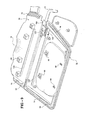
FIG. 2 is an elevational view of an open clam shell core for the sun visor shown in FIG. 1, depicting the initial step of attaching the fabric cover to the core;
FIG. 3 is an enlarged, cross-sectional view of one corner of the clam shell core in the closed position showing the edge fold and edge material attached to the core;
FIG. 4 is an enlarged, perspective view of the corner of the core shown in FIG. 3;
FIG. 5 is an exploded, perspective view of the slide carrier, clip and large support rod according to one aspect of the present invention;
FIG. 6 is a cross sectional view showing the slider carrier, clip and support rod in a closed core position;
FIG. 7 is a perspective view of the sun visor of FIG. 1 depicting the slider means in the normal, retracted position;
FIG. 8 is a perspective view similar to FIG. 7, but showing the slide carrier in the fully extended sun visor position;
FIG. 9 is a perspective view of the sun visor of FIG. 1 having a short length, non-telescoping support arm;
FIG. 10 is a perspective view of another aspect of the sun visor according to the present invention shown in an open core position and depicting the mounting of a mirror to one core half;
FIG. 11 is a perspective view of a completed sun visor showing one aspect of a fully optioned mirror assembly with a cover deployed in a closed position;
FIG. 12 is a perspective view, similar to FIG. 11, but with the cover deployed in an open position;
FIG. 13 is a cross-sectional view through the sun visor of FIG. 11 depicting the mounting of the mirror assembly to the core and cover;
FIG. 14 is a perspective view of another aspect of a sun visor according to the present invention having a mirror assembly mounted therein; and
FIG. 15 is a cross-sectional view of an alternate aspect of the sun visor of the present invention.
DETAILED DESCRIPTION
Referring now to the drawings, and to FIGS. 1-14 in particular, there is depicted a sun visor denoted generally by reference number 10 which includes a number of features, all described hereafter, which may be used in various combinations as well as individually, separate from the other features.
In general, the sun visor 10 includes a core 12, a cover 14 typically made of fabric, including synthetics and natural fabrics, a support arm formed of either a long length support arm 16 allowing telescoping movement of the sun visor 10 as described hereafter and as shown in FIGS. 7 and 8 or a short length support arm 18 shown in FIG. 9 which does not provide telescoping extension of the sun visor 10. The sun visor 10 may also include a mirror assembly shown in various feature combinations in FIGS. 11-14.
Referring now to FIGS. 2-4, the core 12 is in the form of a clam shell having a first clam shell portion or half 20 and a second portion or half 22. The core 12 is formed of a suitable, light weight, easily formed material, such as plastic. A plastic useable to form the core 12 maybe polypropylene, by example only.
The first and second core halves 20 and 22 are integrally and pivotally joined together along a living hinge portion or edge 24 extending between one longitudinal edge of each of the core halves 20 and 22.
The core halves 20 and 22 have a substantially mirror image configuration formed of opposed longitudinal edges joined together to form the living hinge 24, outer longitudinal edges 26 and 28, adjacent side edges 30 and 32, and adjacent side edges 34 and 36. The side edges 26 and 28 may optionally be formed as part of a pivotal flap section pivotable about a second living hinge or weakened portion 38 formed adjacent from each side edge 26 and 28.
As shown in FIGS. 1 and 2, an intermediate portion between the side edges 30 and 32 and an intermediate portion 40 between the side edges 30 and 32 of the first and second core halves 20 and 22, respectively, is recessed to form a space for insertion of one support arm 16 or 18 into the core 12. An end portion of the living hinge 24 between the core halves 20 and 22 is formed with an aperture 42 which, when the core 12 is in the closed, fully assembled position shown in FIG. 1, defines an open ended recess adapted for receiving a D-ring 44 for securing one end of the sun visor 10 to a latch member mounted in a vehicle head liner, not shown. The D-ring 44 is mounted in the core 12 by suitable clips, not shown.
The core 12 of the present invention is provided with a unique cover mounting means which insures a quick and secure mounting of the cover 14 on the outer surface of the core 12.
The cover mounting means includes an elongated, elevated cover attachment surfaces 50 and 52 respectively formed in the core halves 20 and 22. Each surface 50 and 52 is formed as one elongated projection extending between the side edges 30 and 34 and the side edges 32 and 36 or in a discontinuous fashion formed of multiple segments or projections. Each surface 50 and 52 terminates in a suitably formed outer mounting surface 54 and 56, respectively. Each surface 54 and 56 may be planar or have any other shape, such a smoothly curved concave or convex shape.
In the aspect of the surfaces 50 and 52 shown in FIGS. 2 and 3, each surface 50 and 52 has a generally C-shape, formed as a continuous member projecting outward from the main extent or plane of the core halves 20 and 22.
In attaching the cover 14 to the core 12, the core 12 and the cover 14 are juxtaposed as shown in FIG. 2 with cover 14 overlaying an outer surface of the core 12. In this arrangement, the outer peripheral edge of the cover 14 shown by reference number 58 projects outward beyond the periphery of the side edges 30, 32, 34 and 36 of the core 12. The outer peripheral edge 58 of the cover 14 is then folded over a peripheral lip 60 and 62 on each core half 20 and 22 and inward to a position in which the peripheral edge 58 of the cover 14 is in contact with and overlays each of the surfaces 54 and 56 on the surfaces 50 and 52. Sonic waves are then applied to the surfaces 50 and 52 to cause molecular vibration and melting of the surfaces 50 and 52 into the interstices of the cover thereby joining the cover 14 to the core halves 20 and 22, after cooling, in a secure connection or joint which extends substantially continuously about the entire periphery of the core 12.
As shown in FIGS. 2-4, alignment and stability enhancing members 70, 72, 74 and 76 are formed in complimentary positions in the core halves 20 and 22 so as to be disposed in close proximity with an opposed member, with contact also being possible, as shown in FIGS. 3 and 4, when the core halves 20 and 22 are folded into the closed, fully assembled position. The alignment members 70, 72, 74 and 76 may take any shape, with the generally angular, L-shape shown in FIG. 2 by way of example only.
Lock means are provided for securing locking the core halves 20 and 22 in a fully assembled, closed position shown in FIGS. 3 and 4. The lock means comprises a plurality of posts denoted generally by reference number 80 which are formed of a stem 82 and a head 84 having a radially outward extending periphery formed of at least two side arms 86 and 88. Rather than just two side arms 86 and 88, the entire periphery of the head 84 may be enlarged to a greater diameter or cross-section dimension than the diameter or cross-section of the stem 82 so as to provide an enlarged head which overhangs the outer periphery of the stem 82 as shown in FIG. 3. The posts 80 are deployed at a number of locations on one of the core halves 20 and 22, with the post 80 being shown by way of example only as being mounted on the core half 22.
A plurality of lock receivers 90 are formed in the other core half 20. The lock receivers 90 include an outer wall formed of at least two wall portions 92 and 94, with additional wall portions, including a third wall portion and even a fourth wall portion to form walls 92, 94, 95 and 97 as a completely closed, continuous wall may also be employed. Lock members are resiliently mounted on and extend from an end of at least two of the side walls 92 and 94. The lock members all denoted generally by reference number 96 include a leg 98 which terminates in an outer end 100. The legs 98 of the lock members 96 are disposed at an acute angle from the adjacent side wall 92 or 94 such that the outer end 100 is pivotal about the connection between the legs 98 and the adjacent side walls 92 and 94 of each receiver 90. This pivotal movement allows the head 84 of a complementarity positioned lock post 80 on the mating core half 22 to slide through the space normally existing between two adjacent lock legs 98 thereby urging the outer ends 100 outward until the head 84 snaps past the outer ends 100 of the legs 98. The legs 98 then snap back toward the nominal position and seat against a shoulder formed between the inner surface of the side arms 86 and 88 of the head 84 and the adjacent outer surface of the stem 82 thereby securely locking the lock post 80 in the receiver 90. The same locking process occurs across the entire core 12 at every location of a matingly positioned receiver 90 and lock post 80.
Referring again to FIGS. 1 and 2, and in greater detail in FIGS. 5 and 6, the support arm 16 is mounted within the core 12 prior to locking closure of the core halves 20 and 22 as described above. The support arm may take one of two configurations, including the telescoping, long length support arm 16 shown in FIGS. 7 and 8 and the shorter length support arm 18 shown in FIG. 9 for non-telescoping sun visors.
Regardless of the length of the support arm 16 or 18, the end portion of each support arm 16 or 18 includes at least one and preferably a pair of flats 110 adjacent an outer end 112, with only the support arm 16 being depicted in FIG. 5 by way of example only. The remainder of the support arm 16 may have a circular cross-section, by example only. A stop flange 114 is spaced from the outer end 112 of the support arm 18 to retain the support arm 18 in a slide carrier 120. The carrier 120 defines an integral, one piece body, typically of a molded plastic, having a pair of side arms 122 and 124, each with an aperture 126 and 128, respectively, the apertures 126 and 128 being coaxially aligned for receiving the end portion of the support arm 18 with the flats 110 disposed between the side arms 122 and 124.
A first pair of apertures 130 are formed in a central leg 132 of the slider 120. A second pair of apertures 134 are also formed in the central leg 132 of the slider 120. The pairs of apertures 130 and 134 receive bent edges 136 and 138 of a spring clip 140 to attach the spring clip 140 to the slider 120. The spring clip 140 has an enlarged end portion denoted by reference number 142 which receives the end portion of the support arm 16. A pair of bent portions 144 and 146 on the spring clip 140 resiliently engage the flats 110 on the end of the support arm 18 to exert a biasing force tending to retain the entire sun visor 10 in a fixed position, typically biased in a direction toward the vehicle headliner in a normal, stored sun visor position to minimize buzz, squeaks or rattles. This provides the necessary noise control features for the sun visor 10 of the present invention.
The sun visor 10 has a unique telescoping mount using the slide carrier 120 which may be used by itself or in combination with the heat stake cover attachment described above as well as with or without any of the additional unit features of the sun visor described hereafter.
The slide carrier 120 includes first and second, oppositely directed, open ended channels 150 and 152 which are integrally formed in the carrier 120. The open end of the channel 150 extends oppositely from the open end of the channel 152. The channels 150 and 152 are positioned to engage slide rails 154 and 156, shown in FIGS. 2, 6, 7 and 8 which are integrally formed as part of the core halves 20 and 22, respectively. The slide rails 154 and 156 extend along the length of each core half 20 and 22, generally in parallel with the hinge 24.
When the core halves 20 and 22 are locked in the fully assembled, closed position shown in FIG. 6, the slide rail 154 engages the channel 150 and the opposed slide rail 156 engages the opposite channel 152 in the slider 120. This dual, opposed slide rail and channel configuration securely retains the slider 120 in a constant orientation during all telescoping movement of the sun visor 10 relative to the support arm 16 as described hereafter. The addition of the second channel 150 and the slide rail 154 provides added stability to insure a smooth, even bi-directional telescoping movement of the sun visor 10 along the support arm 16 while at the same time securely retaining the sun visor 10 to the support arm 16.
FIG. 7 depicts the normal, non-telescope position of the sun visor 10 relative to the support arm 16. In this position, the carrier 120 is disposed adjacent to the D-ring end of the sun visor 10. When the vehicle occupant desires to laterally extend the position of the sun visor 10 relative to the support arm 16, the occupant grasps the sun visor 10 and slides the sun visor 10 along the support arm 16 to any position up to a maximum extend position shown in FIG. 8. In the maximum extended position, the carrier 120 is disposed adjacent to a support arm pivot support or clip 160. The clip 160, shown in FIGS. 7, 8 and 9, includes a wall integrally formed on one of the core halves, such as the second core half 22 having an aperture 162 for receiving the support arm 16 therethrough. The portion 164 of the wall 160 carrying the aperture 162 is spaced from a collar 166, also formed on the core half 22, which defines a generally circular cross-section bore through which the support arm 16 extends.
The sun visor 10 may also be provided with the short length support arm 18 for non-telescoping use without any modifications to the core 12. By example only, the non-telescoping aspect of the present sun visor 10 also employs the carrier 120, the support wall 160 and the sleeve 166. However, the carrier 120 is non-laterally moveably disposed within the wall 160 as shown in FIG. 9.
Referring now to FIGS. 10-14, there is depicted several aspects of a mirror assembly which may be optionally employed with the sun visor 10 of the present invention. It will be understood that the various aspects of the mirror assembly described hereafter are useable independently or in combination with any of the telescoping, fabric cover mount or core lock means described above.
In one aspect of a mirror assembly shown in FIG. 10, which preferably applies to all the mirror assemblies described hereafter, a shallow recess 170 is formed in the core half 22 projecting slightly out of the plane of the main extent of the core half 22. The recess 170 is formed by a wall 172.
At least one and preferably a plurality of spaced apertures 174 are formed in the wall 172. Each aperture 174 is alignable with a corresponding lock receiver 90 on the mating core half 20. Each aperture 174 is positioned to receive a lock post 80, identical to the lock post 80 described above for locking the core halves 20 and 22 in the fully closed, assembled position, but now provided on a back plate 176 of a frame or mirror support. The lock posts 80 project from the back wall or plate 176 so as to extend through the apertures 174 and the wall 172 and into locking engagement with the mating receiver 90 when the core halves 20 and 22 are pivoted to the fully closed position. This enables the mirror assembly to be fixedly attached to the core 10 at the same time the core halves 20 and 22 are locked in the closed, fully assembled position.
FIGS. 11 and 12 depict an opposite surface of the core half 22 which has the recess 170 formed therein for receiving a mirror assembly 182. In this aspect of the mirror assembly 182, the mirror assembly 182 includes a moveable or pivotal cover 184 which is pivotally mounted to a frame 186 formed of a fixed frame member 188 attached to the back plate 176 shown in FIG. 10 and a mirror surround frame 190, only a portion of which is shown in FIG. 11. The cover 184 has a generally planar extent, with depending side walls and a raised edge 192 to permit easy pivotal movement of the cover 184 between open and closed positions shown in FIGS. 12 and 11, respectively. A hinge 189 is provided between a fixed frame element 188 and the cover 184.
The mirror assembly 182, as shown in FIG. 12, also is provided with an illumination means in the form of one or more lamp means 196 and 198 mounted in the mirror surround frame 190 on at least one and preferably opposed sides of a reflective mirror 200. The mirror 200 is typically adhesively joined to the back plate 176. Conductors for conducting power to the light means 196 and 198 located below the bezzles or lenses 202 are routed between the closed core halves 20 and 22 and into an aperture formed in the support arm 16 or 18 whereby the wires exit the sun visor 10 and pass through the vehicle interior, typically through the vehicle A pillar to the accessory power vehicle circuit.
According to a unique aspect of the present invention, the mirror assembly 182 is mounted on the sun visor 10 after the core halves 20 and 22 of the sun visor 10 have been pivoted to the closed, latched position. As shown in FIG. 13, the lock post 80 may be forced through the fabric cover 14 into the underlying receiver 90 to fixedly mount the mirror assembly 182 to the sun visor 10. The layer of the cover fabric 14 disposed between the back wall 176 of the mirror assembly 182 and the core half 20 minimizes the generation of buzzes, squeaks and rattles.
It will be understood that the mirror assembly 182 may be provided without the lamp means 196 and 198 and with or without the pivotal cover 184. Another mirror assembly 210 is depicted in FIG. 14. In this aspect, the mirror apparatus is formed of a multi-sided frame 212 which surrounds a mirror 214 secured, typically by adhesive, to a back plate, not shown. The back plate can be identical to the back plate 176 so as to carry the lock posts 80 for secure attachment of the mirror assembly 210 to the core half 22 as described above.
As shown in FIG. 15, the core 10 having the recess 172 formed in one of the core halves for receiving one of the mirror assemblies described above, may also be utilized without any mirror assemble. In this application, a filler member 220 has a peripheral shape complementary to the shape of the recess 170 in the core half 22 and a thickness substantially the same as the depth of the recess 170.
In use, the filler member 220 is mounted within the recess 170 and covered by the cover 14 which holds the filler member 220 in the recess 170. Alternately, the filler member 220 may be fixed in the recess 170 by means of adhesive, etc.
The use of the filler member 220 provides a flush surface with the surrounding surface of the core half 22 when a mirror assembly is not used in the sun visor 10. At the same time, the filler member enables a single core 12 design to be employed with and without a mirror assembly without requiring any modification or additional manufacturing cost.
In summary, there has been disclosed a unique vehicle sun visor having improved fabric cover attachment, easy and reliable telescoping visor movement, the option to switch between a telescoping support arm and a fixed short support arm without modification to the sun visor core so as to contribute to a reduced manufacturing cost, multiple mirror assembly mounts, unique and reliable core lock members, and a mirror attachment means which controls or minimizes the generation of noise between the contacting parts of the mirror and the sun visor core.

Claims (14)

1. A method of manufacturing a sun visor comprising the steps of:
forming a core with first and second core halves extending oppositely from a common hinge;
forming a receiving surface on each of the first and second core halves defining an elongated attachment area spaced from a periphery of the first and second core halves;
overlaying the core and a covers, with edge portions of the cover extending beyond the periphery of the core halves;
folding peripheral edge portions of the cover over peripheral edges of the first and second core halves into contact with the receiving surfaces on the first and second core halves; and
joining the edges of the cover to the receiving surface.
2. The method of claim 1 wherein the step of forming the receiving surfaces comprises:
forming the receiving surface on at least one of the first and second core halves as a continuous surface between opposed ends of the one of the first and second core halves.
3. The method of claim 2 further comprising the step of:
forming an outer end of each receiving surface as a planar surface.
4. The method of claim 1 wherein the step of forming the core further comprises:
forming each of the first and second core halves with opposed sides extending from the common hinge edge, and one longitudinal edge spaced from the common edge; and
forming the receiving surface on each of the first and second core halves along the opposed side edges and the longitudinal edge.
5. The method of claim 1 further comprising the step of:
forming the receiving surfaces in the first and second core halves in a spatial relationship so that the receiving surfaces on the first and second core halves overlay each other in substantial alignment when the first and second core halves are folded together about the common binge edge.
6. A sun visor constructed in accordance with the method of claim 1.
7. A sun visor comprising:
a core with first and second core halves extending oppositely from a common hinge;
a receiving surface defining an elongated attachment area on each of the first and second core halves spaced from a periphery of the first and second core halves;
the core overlaid with a cover, with edge portions of the cover extending beyond the periphery of the core halves;
peripheral edge portions of the cover folded over peripheral edges of the first and second core halves into contact with the receiving surfaces on the first and second core halves; and
the peripheral edges of the cover folded over and joined to the receiving surfaces.
8. The sun visor of claim 7 wherein:
the receiving surface on at least one of the first and second core halves extends continuously between opposed ends.
9. The sun visor of claim 7 further comprising:
a hinge formed at a common edge between the first and second core halves.
10. The sun visor of claim 9 further comprising:
each of the first and second core halves defined by opposed side edges extending from the common edge and one longitudinal edge extending between the opposed side edges and spaced from the common edge; and
the receiving surfaces in each of the first and second core halves extending along the opposed side edges and the longitudinal edge.
11. The sun visor of claim 7 wherein:
the receiving surface in at least one of the first and second core halves defines a planar surface raised from a plane extending through a major extent of at least one of the first and second core halves.
12. The sun visor of claim 7 further comprising:
the receiving surfaces in the first and second core halves disposed in an overlaid, spatial relationship when the first and second core halves are folded together about the common edge.
13. The sun visor of claim 7 wherein:
the peripheral, folded over edges of the cover are welded to the receiving surfaces on the first and second core halves.
14. The method of claim 1 wherein the joining step further comprises the step of:
welding the peripheral, folded over edges of the cover to the receiving surfaces.
US10/262,682 2002-10-02 2002-10-02 Sun visor and cover attachment method Expired - Fee Related US6840561B2 (en)

Priority Applications (9)

Application Number Priority Date Filing Date Title
US10/262,682 US6840561B2 (en) 2002-10-02 2002-10-02 Sun visor and cover attachment method
PCT/US2003/031069 WO2004030964A1 (en) 2002-10-02 2003-10-01 Sun visor and cover attachment method
DE60320022T DE60320022T2 (en) 2002-10-02 2003-10-01 SUNSHADE AND ASSOCIATED MOUNTING METHOD FOR THEIR REFERENCE
EP03759631A EP1575794B1 (en) 2002-10-02 2003-10-01 Sun visor and cover attachment method
AU2003275355A AU2003275355A1 (en) 2002-10-02 2003-10-01 Sun visor and cover attachment method
MXPA05003375A MXPA05003375A (en) 2002-10-02 2003-10-01 Sun visor and cover attachment method.
ES03759631T ES2304528T3 (en) 2002-10-02 2003-10-01 PARASOL AND PROCEDURE FOR HOLDING A LINING.
CN200380104779.1A CN1738729A (en) 2002-10-02 2003-10-01 Sun visor and cover attachment method
AT03759631T ATE390310T1 (en) 2002-10-02 2003-10-01 SUN VISOR AND ASSOCIATED FASTENING METHOD FOR THEREOF

Applications Claiming Priority (1)

Application Number Priority Date Filing Date Title
US10/262,682 US6840561B2 (en) 2002-10-02 2002-10-02 Sun visor and cover attachment method

Publications (2)

Publication Number Publication Date
US20040066056A1 US20040066056A1 (en) 2004-04-08
US6840561B2 true US6840561B2 (en) 2005-01-11

Family

ID=32041863

Family Applications (1)

Application Number Title Priority Date Filing Date
US10/262,682 Expired - Fee Related US6840561B2 (en) 2002-10-02 2002-10-02 Sun visor and cover attachment method

Country Status (9)

Country Link
US (1) US6840561B2 (en)
EP (1) EP1575794B1 (en)
CN (1) CN1738729A (en)
AT (1) ATE390310T1 (en)
AU (1) AU2003275355A1 (en)
DE (1) DE60320022T2 (en)
ES (1) ES2304528T3 (en)
MX (1) MXPA05003375A (en)
WO (1) WO2004030964A1 (en)

Cited By (14)

* Cited by examiner, † Cited by third party
Publication number Priority date Publication date Assignee Title
US20060006689A1 (en) * 2002-05-08 2006-01-12 Fernandez Miguel A Coated sun visor
US20060061127A1 (en) * 2004-09-20 2006-03-23 Emerling David M Molded automotive visor
US20060261627A1 (en) * 2005-04-01 2006-11-23 Johnson Controls Technology Company Visor and method for making a visor
US20060267369A1 (en) * 2005-05-13 2006-11-30 Lear Corporation Sun visor detent spring clip
US7192075B1 (en) * 2003-03-26 2007-03-20 Kyowa Sangyo Co., Ltd. Sun visor for vehicle and method of manufacturing the same
US20080093876A1 (en) * 2004-08-30 2008-04-24 Johnson Controls Technology Company Visor for a Vehicle
US20080217950A1 (en) * 2007-03-05 2008-09-11 Lear Corporation Visor Assembly Incorporating an Electronic Control Module
US20110012387A1 (en) * 2008-01-31 2011-01-20 Johnson Control Technology Company Injection-molded mold-behind sun visor
US20110227362A1 (en) * 2008-10-15 2011-09-22 Johnson's Control Technology Company Channel for slide-on-rod visors
US8556325B2 (en) 2011-09-20 2013-10-15 Irvin Automotive Products, Inc. Sliding visor
US10688850B2 (en) 2018-03-13 2020-06-23 Irvin Automotive Products, LLC Sliding visor
US10864804B2 (en) 2019-02-28 2020-12-15 Irvin Automotive Products, LLC Sliding thin visor
US10870337B2 (en) 2019-02-28 2020-12-22 Irvin Automotive Products, LLC Thin visor
US11396220B2 (en) 2014-12-16 2022-07-26 Irvin Automotive Products, LLC Visor

Families Citing this family (9)

* Cited by examiner, † Cited by third party
Publication number Priority date Publication date Assignee Title
US20050248189A1 (en) * 2004-05-07 2005-11-10 Lear Corporation Vehicle seat incorporating a seat back panel
US7152901B2 (en) * 2004-10-22 2006-12-26 Innotec Corporation Vehicle visor construction and method
JP2006219012A (en) * 2005-02-10 2006-08-24 Kyowa Sangyo Kk Sun visor for vehicle
IL184285A0 (en) * 2007-06-28 2007-10-31 Wangenheim Keren Elen Hardened fabric product and production process therefor
JP5410424B2 (en) * 2007-07-27 2014-02-05 ジョンソン コントロールズ テクノロジー カンパニー Composite headliner with improved acoustic performance
WO2009042822A1 (en) * 2007-09-27 2009-04-02 Johnson Controls Technology Company Visor made from a vehicle panel material
WO2010077087A2 (en) 2008-12-30 2010-07-08 Lg Electronics Inc. Laundry machine
JP5710942B2 (en) * 2010-11-12 2015-04-30 共和産業株式会社 Vehicle sun visor
JP6835621B2 (en) * 2017-02-20 2021-02-24 共和産業株式会社 Vehicle sun visor

Citations (49)

* Cited by examiner, † Cited by third party
Publication number Priority date Publication date Assignee Title
US4227241A (en) * 1978-10-23 1980-10-07 Prince Corporation Visor assembly
US4458938A (en) * 1981-02-18 1984-07-10 Gebr. Happich Gmbh Attachment of covering on sun visor for vehicles
US4763946A (en) * 1987-06-08 1988-08-16 Prince Corporation Visor
US4858983A (en) 1988-04-04 1989-08-22 White Jay E Sun visor frame and mounting structure
US4890875A (en) 1985-05-16 1990-01-02 Taneyuki Takahashi Sun visor for automobile
US4925233A (en) 1987-12-28 1990-05-15 Prince Corporation Adjustable visor
US4998765A (en) 1989-02-21 1991-03-12 Prince Corporation Sliding visor
US5007532A (en) 1989-11-20 1991-04-16 Prince Corporation Visor and method for making the same
US5031951A (en) 1989-11-20 1991-07-16 Prince Corporation Sun visor
US5031950A (en) 1990-08-22 1991-07-16 Plasta Fiber Industries, Inc. Sunvisor with covering attachment mechanism
US5056852A (en) 1991-02-04 1991-10-15 Plasta Fiber Industries, Inc. Vehicle sunvisor including mechanism for securing covering on sunvisor and supporting sunvisor within vehicle and method of making same
US5108143A (en) 1990-07-27 1992-04-28 Neo-Ex Lab. Inc. Sun visor and process for manufacturing the same
US5209880A (en) * 1990-07-27 1993-05-11 Neo-Ex Lab. Inc. Process for making a sun visor by molding a pair of shells and bonding them together
US5301994A (en) 1992-10-14 1994-04-12 Plasta Fiber Industries Corp. Dual synchronous opening mirror doors for sun visors
US5308136A (en) * 1992-07-08 1994-05-03 Eugen Zipperle Gmbh & Co., Kg Sun visor for motor-powered vehicles
US5308137A (en) * 1992-12-18 1994-05-03 Gebr. Happich Gmbh Sun visor for vehicles and method and apparatus for the manufacture thereof
US5338082A (en) 1992-04-15 1994-08-16 Plasta Fiber Industries Corp. Apparatus for securing fabric to a visor
US5411309A (en) 1992-02-04 1995-05-02 Fico I.T.M. S.A. Automobile sun visor
US5556154A (en) * 1994-10-25 1996-09-17 Gebr. Happich Gmbh Visor with two-part core
US5580118A (en) 1995-08-14 1996-12-03 Crotty, Iii; Willard E. Sun visor having an alignment element
US5678879A (en) 1994-07-14 1997-10-21 Benecke-Kaliko Ag Sun visor for vehicles
US5695237A (en) * 1996-04-12 1997-12-09 Pince Corporation Visor and method of manufacture
US5716092A (en) * 1996-06-11 1998-02-10 Prince Corporation Visor and method of manufacturing
EP0826533A2 (en) 1996-08-27 1998-03-04 Crotty Corporation A modular sun visor assembly and method of assembling a sun visor
US5871252A (en) 1996-07-30 1999-02-16 Lear Corporation Telescopic sunvisor
US5887933A (en) * 1997-07-15 1999-03-30 Lear Corporation Sun visor
US5895087A (en) 1996-03-09 1999-04-20 Becker Group Europe Gmbh Sun visor for vehicles
US5924748A (en) 1997-04-14 1999-07-20 Ut Automotive Dearborh, Inc. Visor torque control
US5934734A (en) 1998-02-12 1999-08-10 Lear Corporation Slidable sun visor with selectively engageable anti-backlash device
US5984399A (en) 1997-07-23 1999-11-16 Becker Group Europe Gmbh Sun visor for vehicles
US6021986A (en) 1997-07-24 2000-02-08 Lear Automotive Dearborn, Inc. Snap-in mount
US6033005A (en) 1998-10-07 2000-03-07 Crotty Corporation Molded polymer sun visor with fused upholstery cover
US6042172A (en) 1998-06-18 2000-03-28 Lear Automotive Dearborn, Inc. Torque control member for a visor assembly
US6058862A (en) 1997-11-27 2000-05-09 Brother Kogyo Kabushiki Kaisha Link-member swinging apparatus
US6120086A (en) 1998-05-15 2000-09-19 Lear Donnelly Overhead Systems, Llc Vehicle visor having snap-in support pin
US6126302A (en) 1997-11-03 2000-10-03 Corn; Jack E. Recessed slide out vanity mirror assembly
US6131985A (en) * 1995-08-14 2000-10-17 Crotty Corporation Modular sun visor assembly and method of assembling a sun visor
US6139083A (en) 1998-04-24 2000-10-31 Lear-Donnelly Overhead Systems, Llc Sliding core visor
US6189949B1 (en) 1998-01-05 2001-02-20 Lear Donnelly Overhead Systems L.L.C. Visor with extender blade and guide therefor
DE19952442A1 (en) 1999-10-30 2001-05-10 Johnson Contr Interiors Gmbh Vehicle sun visor comprise blow-molded body encased in decorative material cut-outs and fixed to body by two fame halves
US6302467B1 (en) 1999-03-01 2001-10-16 Crotty Corp Sun visor assembly having a rounded edge
US6557920B1 (en) * 2002-03-12 2003-05-06 Crotty Corporation Sun visor assembly having a flexible ear
US6578895B1 (en) * 2001-12-05 2003-06-17 Crotty Corporation Sun visor having a corrugated core
US6604772B2 (en) * 2001-11-09 2003-08-12 Lear Corporation Extender blade mounting frame for a sun visor
US6634696B1 (en) * 2003-01-09 2003-10-21 Lear Corporation Snap frame visor
US6641198B2 (en) * 2001-02-16 2003-11-04 Crotty Corporation Clip lock visor
US6641197B1 (en) * 2000-02-29 2003-11-04 Crotty Corporation Sun visor assembly having a rounded edge
US6698814B1 (en) * 2002-10-02 2004-03-02 Grupo Antolin Ingenieria, S.A. Slidable sun visor
US6698815B1 (en) * 2002-10-02 2004-03-02 Grupo Antolin Ingenieria, S.A. Sun visor with mirror assembly

Family Cites Families (1)

* Cited by examiner, † Cited by third party
Publication number Priority date Publication date Assignee Title
FR2727904A1 (en) * 1994-12-13 1996-06-14 Rockwell Bcs France Sun visor for use in passenger compartment of vehicles

Patent Citations (52)

* Cited by examiner, † Cited by third party
Publication number Priority date Publication date Assignee Title
US4227241A (en) * 1978-10-23 1980-10-07 Prince Corporation Visor assembly
US4458938A (en) * 1981-02-18 1984-07-10 Gebr. Happich Gmbh Attachment of covering on sun visor for vehicles
US4890875A (en) 1985-05-16 1990-01-02 Taneyuki Takahashi Sun visor for automobile
US4763946A (en) * 1987-06-08 1988-08-16 Prince Corporation Visor
US4925233A (en) 1987-12-28 1990-05-15 Prince Corporation Adjustable visor
US4858983A (en) 1988-04-04 1989-08-22 White Jay E Sun visor frame and mounting structure
US4998765A (en) 1989-02-21 1991-03-12 Prince Corporation Sliding visor
US5007532A (en) 1989-11-20 1991-04-16 Prince Corporation Visor and method for making the same
US5031951A (en) 1989-11-20 1991-07-16 Prince Corporation Sun visor
US5209880A (en) * 1990-07-27 1993-05-11 Neo-Ex Lab. Inc. Process for making a sun visor by molding a pair of shells and bonding them together
US5108143A (en) 1990-07-27 1992-04-28 Neo-Ex Lab. Inc. Sun visor and process for manufacturing the same
US5031950A (en) 1990-08-22 1991-07-16 Plasta Fiber Industries, Inc. Sunvisor with covering attachment mechanism
US5056852A (en) 1991-02-04 1991-10-15 Plasta Fiber Industries, Inc. Vehicle sunvisor including mechanism for securing covering on sunvisor and supporting sunvisor within vehicle and method of making same
US5411309A (en) 1992-02-04 1995-05-02 Fico I.T.M. S.A. Automobile sun visor
US5338082A (en) 1992-04-15 1994-08-16 Plasta Fiber Industries Corp. Apparatus for securing fabric to a visor
US5308136A (en) * 1992-07-08 1994-05-03 Eugen Zipperle Gmbh & Co., Kg Sun visor for motor-powered vehicles
US5301994A (en) 1992-10-14 1994-04-12 Plasta Fiber Industries Corp. Dual synchronous opening mirror doors for sun visors
US5466405A (en) * 1992-12-18 1995-11-14 Gerb. Happich Gmbh Method for the manufacture of a sun visor
US5308137A (en) * 1992-12-18 1994-05-03 Gebr. Happich Gmbh Sun visor for vehicles and method and apparatus for the manufacture thereof
US5678879A (en) 1994-07-14 1997-10-21 Benecke-Kaliko Ag Sun visor for vehicles
US5556154A (en) * 1994-10-25 1996-09-17 Gebr. Happich Gmbh Visor with two-part core
US5580118A (en) 1995-08-14 1996-12-03 Crotty, Iii; Willard E. Sun visor having an alignment element
US6131985A (en) * 1995-08-14 2000-10-17 Crotty Corporation Modular sun visor assembly and method of assembling a sun visor
US5895087A (en) 1996-03-09 1999-04-20 Becker Group Europe Gmbh Sun visor for vehicles
US5695237A (en) * 1996-04-12 1997-12-09 Pince Corporation Visor and method of manufacture
US5716092A (en) * 1996-06-11 1998-02-10 Prince Corporation Visor and method of manufacturing
US5871252A (en) 1996-07-30 1999-02-16 Lear Corporation Telescopic sunvisor
EP0826533A2 (en) 1996-08-27 1998-03-04 Crotty Corporation A modular sun visor assembly and method of assembling a sun visor
US5924748A (en) 1997-04-14 1999-07-20 Ut Automotive Dearborh, Inc. Visor torque control
US5887933A (en) * 1997-07-15 1999-03-30 Lear Corporation Sun visor
US5984399A (en) 1997-07-23 1999-11-16 Becker Group Europe Gmbh Sun visor for vehicles
US6021986A (en) 1997-07-24 2000-02-08 Lear Automotive Dearborn, Inc. Snap-in mount
US6126302A (en) 1997-11-03 2000-10-03 Corn; Jack E. Recessed slide out vanity mirror assembly
US6058862A (en) 1997-11-27 2000-05-09 Brother Kogyo Kabushiki Kaisha Link-member swinging apparatus
US6189949B1 (en) 1998-01-05 2001-02-20 Lear Donnelly Overhead Systems L.L.C. Visor with extender blade and guide therefor
US5934734A (en) 1998-02-12 1999-08-10 Lear Corporation Slidable sun visor with selectively engageable anti-backlash device
US6139083A (en) 1998-04-24 2000-10-31 Lear-Donnelly Overhead Systems, Llc Sliding core visor
US6120086A (en) 1998-05-15 2000-09-19 Lear Donnelly Overhead Systems, Llc Vehicle visor having snap-in support pin
US6042172A (en) 1998-06-18 2000-03-28 Lear Automotive Dearborn, Inc. Torque control member for a visor assembly
US6033005A (en) 1998-10-07 2000-03-07 Crotty Corporation Molded polymer sun visor with fused upholstery cover
US6302467B1 (en) 1999-03-01 2001-10-16 Crotty Corp Sun visor assembly having a rounded edge
US6367861B1 (en) 1999-03-01 2002-04-09 Crotty Corporation Sun visor assembly having a rounded edge
US6409245B1 (en) * 1999-03-01 2002-06-25 Crotty Corp Sunvisor assembly having a rounded edge
DE19952442A1 (en) 1999-10-30 2001-05-10 Johnson Contr Interiors Gmbh Vehicle sun visor comprise blow-molded body encased in decorative material cut-outs and fixed to body by two fame halves
US6641197B1 (en) * 2000-02-29 2003-11-04 Crotty Corporation Sun visor assembly having a rounded edge
US6641198B2 (en) * 2001-02-16 2003-11-04 Crotty Corporation Clip lock visor
US6604772B2 (en) * 2001-11-09 2003-08-12 Lear Corporation Extender blade mounting frame for a sun visor
US6578895B1 (en) * 2001-12-05 2003-06-17 Crotty Corporation Sun visor having a corrugated core
US6557920B1 (en) * 2002-03-12 2003-05-06 Crotty Corporation Sun visor assembly having a flexible ear
US6698814B1 (en) * 2002-10-02 2004-03-02 Grupo Antolin Ingenieria, S.A. Slidable sun visor
US6698815B1 (en) * 2002-10-02 2004-03-02 Grupo Antolin Ingenieria, S.A. Sun visor with mirror assembly
US6634696B1 (en) * 2003-01-09 2003-10-21 Lear Corporation Snap frame visor

Cited By (21)

* Cited by examiner, † Cited by third party
Publication number Priority date Publication date Assignee Title
US20060006689A1 (en) * 2002-05-08 2006-01-12 Fernandez Miguel A Coated sun visor
US7086681B2 (en) * 2002-05-08 2006-08-08 Fico I.T.M., S.A. Coated sun visor
US7192075B1 (en) * 2003-03-26 2007-03-20 Kyowa Sangyo Co., Ltd. Sun visor for vehicle and method of manufacturing the same
US20080093876A1 (en) * 2004-08-30 2008-04-24 Johnson Controls Technology Company Visor for a Vehicle
US7866724B2 (en) * 2004-08-30 2011-01-11 Johnson Controls Technology Company Visor for a vehicle
US20060061127A1 (en) * 2004-09-20 2006-03-23 Emerling David M Molded automotive visor
US20060261627A1 (en) * 2005-04-01 2006-11-23 Johnson Controls Technology Company Visor and method for making a visor
US20060267369A1 (en) * 2005-05-13 2006-11-30 Lear Corporation Sun visor detent spring clip
US20080217950A1 (en) * 2007-03-05 2008-09-11 Lear Corporation Visor Assembly Incorporating an Electronic Control Module
US7458627B2 (en) 2007-03-05 2008-12-02 Lear Corporation Visor assembly incorporating an electronic control module
US20110012387A1 (en) * 2008-01-31 2011-01-20 Johnson Control Technology Company Injection-molded mold-behind sun visor
US20110227362A1 (en) * 2008-10-15 2011-09-22 Johnson's Control Technology Company Channel for slide-on-rod visors
US8434811B2 (en) * 2008-10-15 2013-05-07 Johnson Controls Technology Company Channel for slide-on-rod visors
US8556325B2 (en) 2011-09-20 2013-10-15 Irvin Automotive Products, Inc. Sliding visor
US9186962B2 (en) 2011-09-20 2015-11-17 Irvin Automotive Products, Inc. Sliding visor
US9770965B2 (en) 2011-09-20 2017-09-26 Irvin Automotive Products, LLC Sliding visor
US11396220B2 (en) 2014-12-16 2022-07-26 Irvin Automotive Products, LLC Visor
US10688850B2 (en) 2018-03-13 2020-06-23 Irvin Automotive Products, LLC Sliding visor
US11312211B2 (en) 2018-03-13 2022-04-26 Irvin Automotive Products, LLC Sliding visor
US10864804B2 (en) 2019-02-28 2020-12-15 Irvin Automotive Products, LLC Sliding thin visor
US10870337B2 (en) 2019-02-28 2020-12-22 Irvin Automotive Products, LLC Thin visor

Also Published As

Publication number Publication date
AU2003275355A1 (en) 2004-04-23
EP1575794A1 (en) 2005-09-21
CN1738729A (en) 2006-02-22
MXPA05003375A (en) 2005-10-18
WO2004030964A1 (en) 2004-04-15
DE60320022T2 (en) 2009-04-16
US20040066056A1 (en) 2004-04-08
ATE390310T1 (en) 2008-04-15
ES2304528T3 (en) 2008-10-16
DE60320022D1 (en) 2008-05-08
EP1575794B1 (en) 2008-03-26

Similar Documents

Publication Publication Date Title
US6840561B2 (en) Sun visor and cover attachment method
US6692059B1 (en) Sun visor with clam shell core attachment snaps
US6698814B1 (en) Slidable sun visor
US6698815B1 (en) Sun visor with mirror assembly
US5365416A (en) Sun visor with integral core
BR112014006474B1 (en) SLIDING PARASOL AND METHOD OF MANUFACTURING A PARASOL
JPS60124520A (en) Sun-visor for automobile
US4570991A (en) Sun visor stowed on pillar
JP2011046376A (en) Convertible top cover and head liner mutually connected to each other by bow
US6604772B2 (en) Extender blade mounting frame for a sun visor
US8740282B2 (en) Vehicular sun visor
JPH0657493B2 (en) Automotive sun visor
US20090218845A1 (en) Visor and method of making a visor
US6120086A (en) Vehicle visor having snap-in support pin
KR200280292Y1 (en) Blackout curtain assembly
KR100872433B1 (en) Shade curtain assembly for car
KR200173420Y1 (en) Mirror assembly of a car
WO2020260511A1 (en) Main body element of a sun visor assembly, sun visor assembly having such a main body element, and method for assembling a sun visor
JPH0958274A (en) Sunshade for automobile equipped with sunroof
KR100840001B1 (en) Semi automatic sun visor for automobile
KR100736967B1 (en) Sunvisor assembly
JP2005219627A (en) Sun visor device of automobile
EP2135760A1 (en) Vehicular sun visor

Legal Events

Date Code Title Description
AS Assignment

Owner name: GRUPO ANTOLIN INGENIERIA, S.A., SPAIN

Free format text: ASSIGNMENT OF ASSIGNORS INTEREST;ASSIGNOR:MILLS, DONALD;REEL/FRAME:013591/0912

Effective date: 20021002

REMI Maintenance fee reminder mailed
FPAY Fee payment

Year of fee payment: 4

SULP Surcharge for late payment
FEPP Fee payment procedure

Free format text: PAT HOLDER CLAIMS SMALL ENTITY STATUS, ENTITY STATUS SET TO SMALL (ORIGINAL EVENT CODE: LTOS); ENTITY STATUS OF PATENT OWNER: SMALL ENTITY

FPAY Fee payment

Year of fee payment: 8

REMI Maintenance fee reminder mailed
LAPS Lapse for failure to pay maintenance fees
STCH Information on status: patent discontinuation

Free format text: PATENT EXPIRED DUE TO NONPAYMENT OF MAINTENANCE FEES UNDER 37 CFR 1.362

FP Lapsed due to failure to pay maintenance fee

Effective date: 20170111